

Page 1

Thermalright
Macho X2
Page 2

Page 3

× 1
× 1
4
4
8
× 1
× 1
× 4
× 4 × 1
× 4 × 8
× 7
× 5
× 4
× 4
Macho X2
Assembly package
× 1
× 1
Page 4

Macho X2
17
Exploded View
Intel 775/1156/1366/1155/1150
Macho Heatsink Body
Fan Clip
TY-142
Screw Nut
Anti-Vibration Pads
Mounting Plate
M3 L6 Screw
Anchoring Mount
Intel Washer (small)
Metal Back Plate
M3 L10 Screw
Mylar Film
Page 5

The Ultimate Cooling Solutions!
www.thermalright.com
2
Component
1
1
2
2
3
3 4
4
5
5
6
6
87
7 8
10
9
10
13
16
1817
11
14
17 18
13 14
12
15
1615
9
1211
Macho Heatsink Body ×1
LGA201 1 T ype B
Screw Pillars x4
Mylar Film x 1
Fan Clip ×4
TY-142 ×2
Thermal paste ×1
AMD Washer (big) ×4
Mounting Plate ×1
Metal Back Plate ×1
M3 L10 Screw ×5
Anti-Vibration Pad ×8
Anchoring Mount ×1
Screw Nut ×4
Intel Washer (small) ×4
M3 L6 Screw ×7
Backplate Cap ×1
Screw Driver ×1
PWM Y -Cable ×1
Page 6

3
Installation Instructions:
Step 1:
Step 2:
Step 3: Step 4:
Step 1 : Part Installation
Take out Macho cooler from the paper box.Remove the TY-142 from the cooler by pulling the Fan
Clips upwards in order to give room for ease of installation. And leave the Fan Clips on the Heatsink
Body . Do not remove them. Apply Anti-Vibration Padding to 4 corners on the Heatsink Body.
Step 3 : 775 backplate cap
Note: When installing on a 775 platform, please
rst insert the Back Plate Cap into the opening on
the Back plate, make sure you have the Cap facing
downwards. (Only for 775).
Step 4 : Place the motherboard on top of the Back
Plate. See the four Screw Pillars go through the
four holes around the processor socket.Cap the
four Screw Pillars with the four Screw Nuts.Make
sure the side with a washer is facing the Back
Plate.
1366
775
1150
1155
1156
Step 2 : Backplate Installation
Choose the platform (775/1150/1155/1156/1366) you are in use. Make four M3L10 Screw Pillars go
through the Metal Back Plate and the Mylar lm from bottom towards top.And then place the Metal Back
Plate on the table. Put the four Washers (for Intel) around the Screw Pillars.
Page 7

The Ultimate Cooling Solutions!
www.thermalright.com
4
Step 5: Step 6:
Step 7: Step 8:
Step 9: Step 10:
Step 5 :
Place the Anchoring Mount on the Screw Nuts.
Use the four M3L6 Screws to fix the Anchoring
Mount on to the Screw Pillars.
Step 9 : Fan Installation
Place the included TY-142 onto the Heatsink
Body. And then secure it with the Fan Clips, by
pulling the Fan Clips to place the four ends at the
four holes on the TY-142.
Step 6 : Applying Thermal Paste
Apply the Thermal Paste to the base of the
Heatsink and the surface of the CPU evenly .
Step 7: Mounting Plate Installation
Place the Heatsink Body on top of the CPU. Make
the Mounting Plate go through the Heatsink Body.
Then use the supplied Screw Driver to fasten the
two M3L6 Screws to Secure the Mounting Plate.
Step 8: Easy Access
Pass the supplied Screw
Driver through the central
hole of the Heatsink Body,
for easier access to the
M3L6 Screw underneath
the cooler.
Step 10 : Installation completed
Connect the two TY-142 fans to the PWM Y-Cable
then connect the cable to the CPU PWM Fan
socket on the motherboard. Installation complete.
Page 8

Macho X2
5
Exploded View
Important! Before proceeding with installation, please check for the most
up-to-date instructions at www.thermalright.com
Intel 2011 / 2011-3
Macho Heatsink Body
Fan Clip
TY-142
LGA201 1 T ype B
Screw Pillars
Anti-Vibration Pads
Mounting Plate
M3 L6 Screw
Anchoring Mount
Page 9

The Ultimate Cooling Solutions!
www.thermalright.com
6
Component
1
1
2
2
3
3 4
4
5
5
6
6
87
7 8
10
9
10
13
16
1817
11
14
17 18
13 14
12
15
1615
9
1211
Macho Heatsink Body ×1
LGA201 1 T ype B
Screw Pillars x4
Mylar Film x 1
Fan Clip ×4
TY-142 ×2
Thermal paste ×1
AMD Washer (big) ×4
Mounting Plate ×1
Metal Back Plate ×1
M3 L10 Screw ×5
Anti-Vibration Pad ×8
Anchoring Mount ×1
Screw Nut ×4
Intel Washer (small) ×4
M3 L6 Screw ×7
Backplate Cap ×1
Screw Driver ×1
PWM Y -Cable ×1
Page 10

7
Installation Instructions:
Step 1:
Step 2:
Step 3:
Step 1 : Part Installation
Take out Macho cooler from the paper box.Remove the TY-142 from the cooler by pulling the Fan
Clips upwards in order to give room for ease of installation. And leave the fan clips on the Heatsink Body.
Do not remove them. Apply Anti-Vibration Padding to 4 corners on the Heatsink Body.
Step 2 : Screw Pillar Installation
Place the motherboard on top of the Back Plate. See the four Screw Pillars go through the four holes
around the processor socket.Cap the four Screw Pillars with the four Screw Nuts.Make sure the side with
a washer is facing the Back Plate.
Step 3 : Anchoring Mount Installation
Place the Anchoring Mount on the Screw Nuts. Use the four M3L6 Screws to x the Anchoring Mount on
to the Screw Pillars.
Page 11

Macho X2
The Ultimate Cooling Solutions!
www.thermalright.com
8
Step 4:
Step 5:
Step 7: Step 8:
Step 6:
Step 7 : Fan Installation
Place the included TY-142 onto the Heatsink
Body. And then secure it with the Fan Clips, by
pulling the Fan Clips to place the four ends at the
four holes on the TY-142.
Step 4 : Applying Thermal Paste
Apply the Thermal Paste to the base of the Heatsink and the surface of the CPU evenly .
Step 5: Mounting Plate Installation
Place the Heatsink Body on top of the CPU. Make
the Mounting Plate go through the Heatsink Body.
Then use the supplied Screw Driver to fasten the
two M3L6 Screws to Secure the Mounting Plate.
Step 6: Easy Access
Pass the supplied Screw
Driver through the central
hole of the Heatsink Body,
for easier access to the
M3L6 Screw underneath
the cooler.
Step 8 : Installation completed
Connect the two TY-142 fans to the PWM Y-Cable
then connect the cable to the CPU PWM Fan
socket on the motherboard. Installation complete.
Page 12

Macho X2
9
Exploded View
Important! Before proceeding with installation, please check for the most
up-to-date instructions at www.thermalright.com
Backplate cap
AM2/AM2+/AM3/AM3+/FM1/FM2/FM2+
Macho Heatsink Body
Fan Clip
TY-142
Screw Nut
Anti-Vibration Pads
Mounting Plate
M3 L6 Screw
Anchoring Mount
AMD Washer (big)
Metal Back Plate
M3 L10 Screw
Mylar Film
Page 13

The Ultimate Cooling Solutions!
www.thermalright.com
10
Component
1
1
2
2
3
3 4
4
5
5
6
6
87
7 8
10
9
10
13
16
1817
11
14
17 18
13 14
12
15
1615
9
1211
Macho Heatsink Body ×1
LGA201 1 T ype B
Screw Pillars x4
Mylar Film x 1
Fan Clip ×4
TY-142 ×2
Thermal paste ×1
AMD Washer (big) ×4
Mounting Plate ×1
Metal Back Plate ×1
M3 L10 Screw ×5
Anti-Vibration Pad ×8
Anchoring Mount ×1
Screw Nut ×4
Intel Washer (small) ×4
M3 L6 Screw ×7
Backplate Cap ×1
Screw Driver ×1
PWM Y -Cable ×1
Page 14

11
Installation Instructions:
Step 1:
Step 2:
Step 3: Step 4:
Step 1 : Part Installation
Take out Macho cooler from the paper box. Remove the TY-142 from the cooler by pulling the Fan Clips
upwards in order to give room for ease of installation. And leave the Fan Clips on the Heatsink Body. Do
not remove them. Apply Anti-Vibration Padding to 4 corners on the Heatsink Body.
Step 3 :backplate cap
Note: When installing on a 939 platform, please
first insert the Back Plate Cap into the opening
on the Back plate, make sure you have the Cap
facing downwards. (Only for 939).
Step 4 : Place the motherboard on top of
the Back Plate. See the four Screw Pillars go
through the four holes around the processor
socket.Cap the four Screw Pillars with the four
Screw Nuts.Make sure the side with a washer is
facing the Back Plate.
AMD
Step 2 : Backplate Installation
Choose the platform (AMD) you are in use. Make four M3L10 Screw Pillars go through the Metal Back
Plate and the Mylar lm from bottom towards top. And then place the Metal Back Plate on the table. Put
the four Washers (for AMD) around the Screw Pillars.
Page 15

The Ultimate Cooling Solutions!
www.thermalright.com
12
Step 5:
Step 7:
Step 9:
Step 10:
Step 6:
Step 8:
Step 5 :
Place the Anchoring Mount on the Screw Nuts.
Use the four M3L6 Screws to fix the Anchoring
Mount on to the Screw Pillars.
Step 9 : Fan Installation
Place the included TY-142 onto the Heatsink
Body. And then secure it with the Fan Clips, by
pulling the Fan Clips to place the four ends at the
four holes on the TY-142 .
Step 6 : Applying Thermal Paste
Apply the Thermal Paste to the base of the
Heatsink and the surface of the CPU evenly .
Step 7: Mounting Plate Installation
Place the Heatsink Body on top of the CPU. Make
the Mounting Plate go through the Heatsink Body.
Then use the supplied Screw Driver to fasten the
two M3L6 Screws to Secure the Mounting Plate.
Step 8: Easy Access
Pass the supplied Screw
Driver through the central
hole of the Heatsink Body,
for easier access to the
M3L6 Screw underneath
the cooler.
Step 10 : Installation completed
Connect the two TY-142 fans to the PWM Y-Cable
then connect the cable to the CPU PWM Fan
socket on the motherboard. Installation complete.
Page 16

Macho X2
13
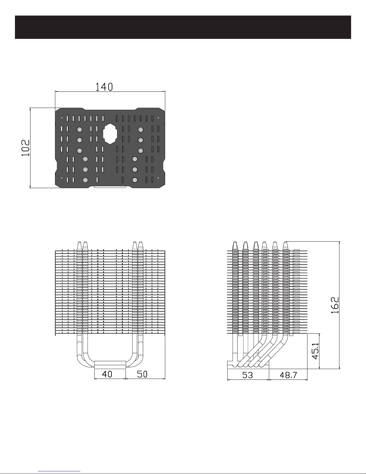
Technical Spec
TY-142 FAN Spec
Dimension: L152mm x H140mm x W26.5mm
Weight: 175g
Rated Speed: 800RPM (PWM controlled)
Noise Level: 15dBA
Air Flow: 45.32CFM
Connector: 4 Pin (PWM Fan connector)
Heatsink Specications:
Dimension: L140mm x W102mm x H162mm
Weight: 710g (Heatsink only)
Heat pipes: 6mm heatpipe*6 units
Fin: T = 0.4 mm ; Gap = 3.1 mm
Fin Pcs: 31 pcs
Copper Base: C1100 Pure copper nickel plated
Motherboard to Fin: 45 + 8 = 53 mm
Page 17
The Ultimate Cooling Solutions!
www.thermalright.com
14
Page 18

Macho X2
15
Awards
Page 19

The Ultimate Cooling Solutions!
www.thermalright.com
TEL: +886-2-2915-5005
FAX: +886-2-2915-5123
EMAIL: sales@thermalright.com
 Loading...