

Page 1
Thermalright
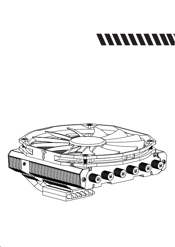
AXP-200R
Page 2

Page 3
AXP-200R
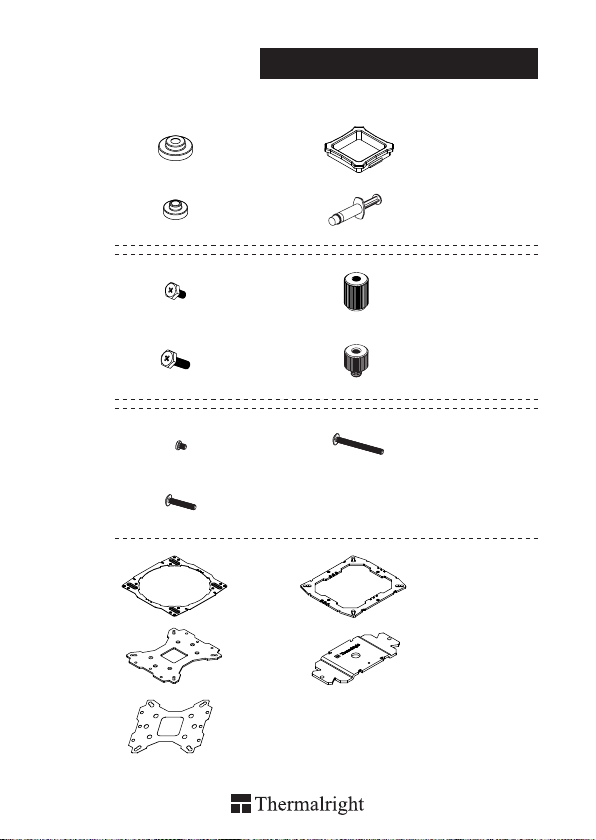
Assembly Package
× 4
× 7
× 5
× 5
× 5
× 1
× 1 × 1
× 1
× 1
× 1× 8
× 4
× 4
× 5
× 1
4
4
4
8
Page 4
AXP-200R
Intel 775/1150/1151/1155/1156/1366
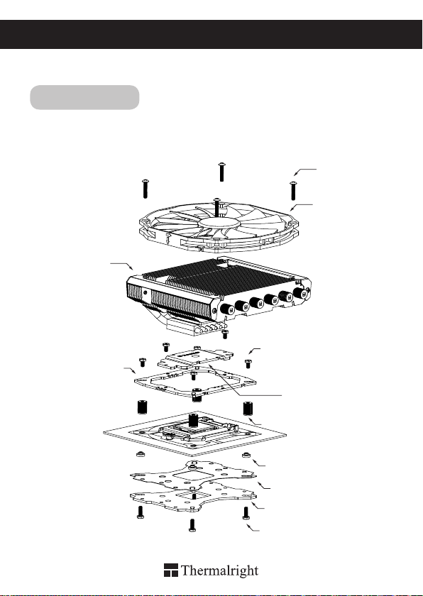
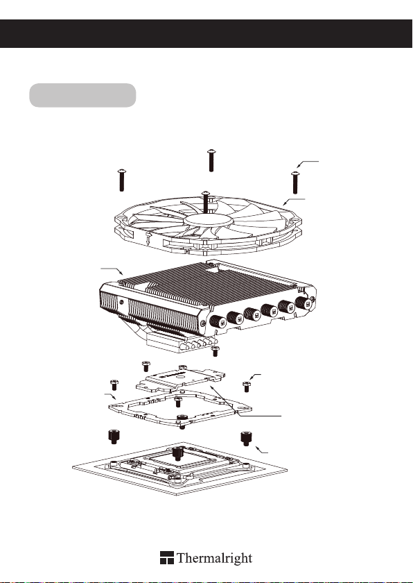
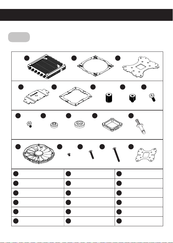
Exploded View
Important! Before proceeding with installation, please check for the most
up-to-date instructions at www.thermalright.com
Heatsink Body
Anchoring Mount
M3 L17 Screw
TY-14013R Fan
M3 L6 Screw
Mounting Plate
Screw Nut
1
Intel Washer (small)
Mylar
Metal Back Plate
M3 L10 Screw
Page 5
The Ultimate Cooling Solutions!
www.thermalright.com
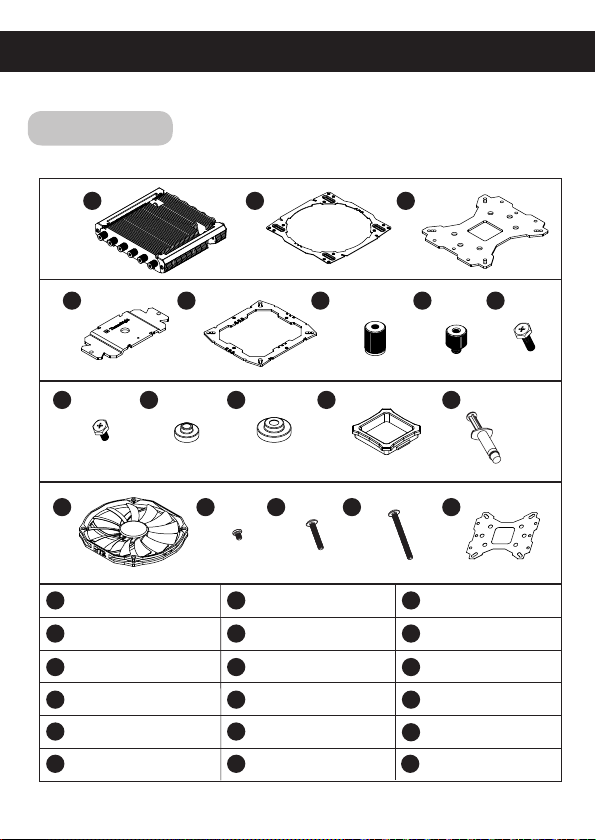
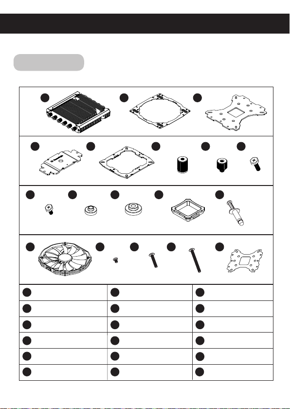
Component
1
4
5
109
14
Heatsink Body ×1
1
Mounting Plate ×1
4
LGA2011 T ype B
7 8
Screw Pillars x4
Intel Washer (small) ×8
10
Chill Factor III ×1
M3 L17 Screw ×5 M3 L28 Screw ×5 Mylar ×1
16 17 18
2
6
11
12
15 16 17
Enhanced Fan Mount ×1
2
Anchoring Mount ×1
5
M3 L10 Screw ×5
AMD Washer (big) ×4
11 12
TY-14013R Fan×1
1413
3
15
7
13
18
Metal Back Plate ×1
3
Screw Nut ×4
6
M3 L6 Screw ×7
9
Back Plate Cap ×1
Screw ×5
M3 L4
8
2
Page 6
Installation Instructions:
Step 1:
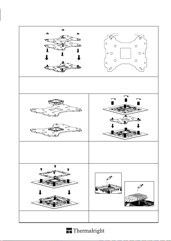
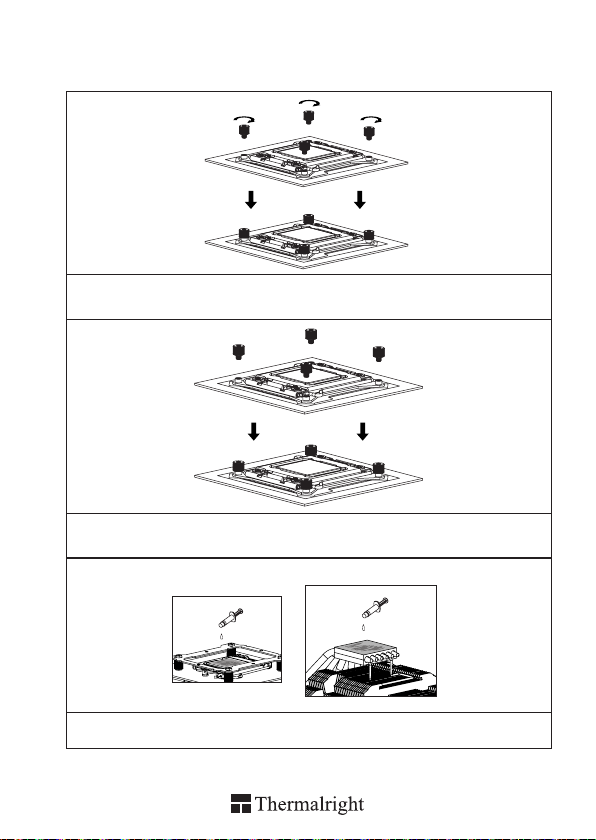
Step 1 : Backplate Installation
Choose the platform (775/1150/1151
Pillars go through the Metal Back Plate and the Mylar film from bottom towards top. And then place the
Metal Back Plate on the table. Put the four Washers (for Intel) around the Screw Pillars.
Step 2:
Step 2 : Back Plate Cap
Note: When installing on a 775 platform, please
rst insert the Back Plate Cap into the opening on
the Back Plate. Make sure you have the Cap facing
downwards. (Only for 775).
Step 4:
/1155/1156/1366) you are in use. Make four M3L10 Screw
Step 3:
Step 3 : Place the motherboard on top of the Back
Plate. See the four Screw Cylinders go through
the four holes around the processor socket.Cap
the four Screw Cylinders with the four Screw Nuts.
Make sure the side with a washer is facing the
Back Plate.
Step 5:
1366
1156
775
1155
1151
1150
Step 4 : Place the Anchoring Mount on the Screw
Nuts. Use the four M3L6 Screws to x
the Anchoring Mount on to the Screw Nuts.
3
Step 5 : Applying Thermal Paste
Apply the Chill Factor III to the base of the
Heatsink and the surface of the CPU evenly.
Page 7
The Ultimate Cooling Solutions!
www.thermalright.com
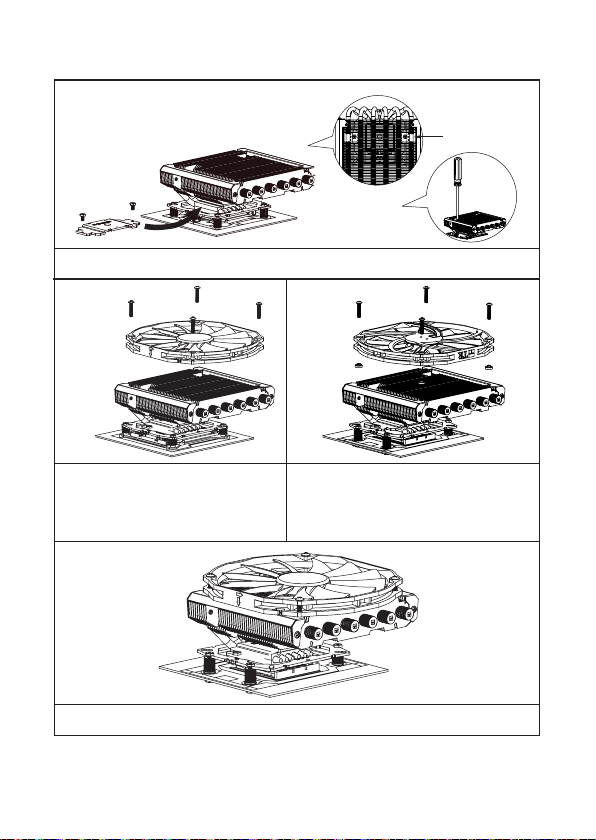
Step 6:
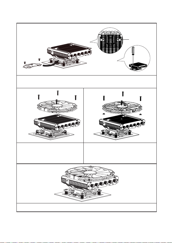
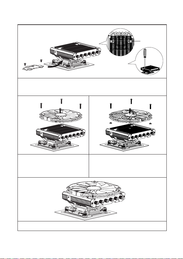
Step 6 : Mounting Plate Installation.
Place the Heatsink Body on top of the CPU. Make the Mounting Plate go through the Heatsink Body.
Then use the two M3L6 screws to secure the Mounting Plate. (Screwdrive goes through holes on ns)
Step 7:
Step 7A : Fan Installation
Place the included TY-14013R fan onto the
heatsink body. And then secure it by screwing
on the four M3L17 screws, through the fan
mounting holes.
Step 8:
Step 8 : Installation Completed
Plug in the fan connector to the CPU PWM Fan socket on the motherboard. Installation complete.
Step 7B : Fan Installation
Or, if the fan is ipped over for drawing air towards
the top as shown in Step 7B, then place four washers
(for Intel boards) underneath the fan for additional
height before securing the fan onto the heatsink body.
4
Page 8
AXP-200R
Intel 2011/2011-3/2066
Exploded View
Important! Before proceeding with installation, please check for the most
up-to-date instructions at www.thermalright.com
Heatsink Body
Anchoring Mount
TY-14013R Fan
M3 L6 Screw
Mounting Plate
M3 L17 Screw
5
LGA 2011
Type B Screw Pillars
Page 9
The Ultimate Cooling Solutions!
www.thermalright.com
Component
1
4
5
109
14
Heatsink Body ×1
1
Mounting Plate ×1
4
LGA2011 T ype B
7 8
Screw Pillars x4
Intel Washer (small) ×8
10
Chill Factor III ×1
M3 L17 Screw ×5 M3 L28 Screw ×5 Mylar ×1
16 17 18
2
6
11
12
15 16 17
Enhanced Fan Mount ×1
2
Anchoring Mount ×1
5
M3 L10 Screw ×5
AMD Washer (big) ×4
11 12
TY-14013R Fan×1
1413
3
15
7
13
18
Metal Back Plate ×1
3
Screw Nut ×4
6
M3 L6 Screw ×7
9
Back Plate Cap ×1
Screw ×5
M3 L4
8
6
Page 10
Installation Instructions:
Step 1:
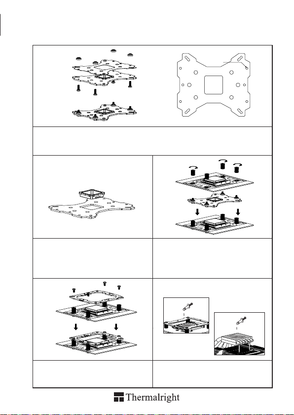
Step 1 : Screw Pillar Installation
Screw on the four LGA2011 T ype B Screw Pillars into the Heatsink studs on the ILM Assembly Frame
around the processor socket.
Step 2:
Step 2 : Anchoring Mount Installation
Place the Anchoring Mount onto the four LGA2011 Type B Screw Pillars, secure it by tightening it with 4
M3L6 Screws.
Step 3:
Step 3 : Applying Thermal Paste
Apply the Chill Factor III to the base of the Heatsink and the surface of the CPU evenly.
7
Page 11
AXP-200R
The Ultimate Cooling Solutions!
www.thermalright.com
Step 4:
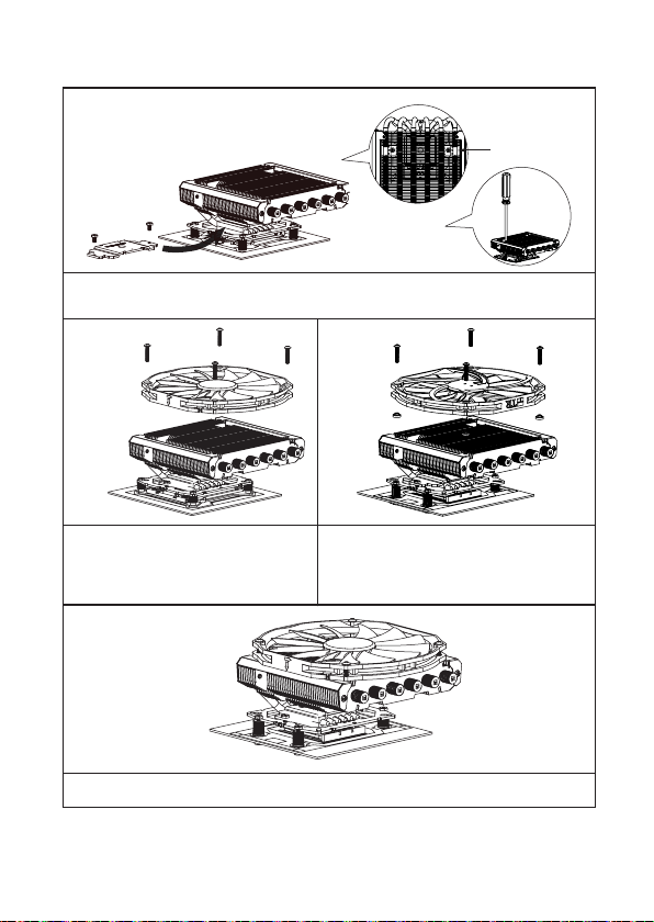
Step 4 : Mounting Plate Installation.
Place the Heatsink Body on top of the CPU. Make the Mounting Plate go through the Heatsink Body.
Then use the two M3L6 screws to secure the Mounting Plate. (Screwdrive goes through holes on
ns)
Step 5:
Step 5A : Fan Installation
Place the included TY-14013R fan onto the
heatsink body. And then secure it by screwing
on the four M3L17 screws, through the fan
mounting holes.
Step 6:
Step 6 : Installation Completed
Plug in the fan connector to the CPU PWM Fan socket on the motherboard. Installation complete.
Step 5B : Fan Installation
Or, if the fan is ipped over for drawing air towards
the top as shown in Step 5B, then place four washers
(for Intel boards) underneath the fan for additional
height before securing the fan onto the heatsink body.
8
Page 12

AXP-200R
AM4/AM2/AM2+/AM3/AM3+/FM1/FM2/FM2+
Exploded View
Important! Before proceeding with installation, please check for the most
up-to-date instructions at www.thermalright.com
Heatsink Body
Anchoring Mount
M3 L17 Screw
TY-14013R Fan
M3 L6 Screw
Mounting Plate
Screw Nut
Back Plate Cap
9
AMD Washer (big)
Mylar
Metal Back Plate
M3 L10 Screw
Page 13

The Ultimate Cooling Solutions!
www.thermalright.com
Component
1
4
5
109
14
Heatsink Body ×1
1
Mounting Plate ×1
4
LGA2011 T ype B
7 8
Screw Pillars x4
Intel Washer (small) ×8
10
Chill Factor III ×1
M3 L17 Screw ×5 M3 L28 Screw ×5 Mylar ×1
16 17 18
2
6
11
12
15 16 17
Enhanced Fan Mount ×1
2
Anchoring Mount ×1
5
M3 L10 Screw ×5
AMD Washer (big) ×4
11 12
TY-14013R Fan×1
1413
3
15
7
13
18
Metal Back Plate ×1
3
Screw Nut ×4
6
M3 L6 Screw ×7
9
Back Plate Cap ×1
Screw ×5
M3 L4
8
10
Page 14
Installation Instructions:
Step 1:
AMD
Step 1 : Backplate Installation
Choose the platform (AMD) you are in use. Make four M3L10 Screw Pillars go through the Metal Back
Plate and the Mylar lm from bottom towards top. And then place the Metal Back Plate on the table. Put
the four Washers (for AMD) around the Screw Pillars.
Step 2: Step 3:
Step 2 : Back Plate Cap
Note: When installing on a 939 platform, please
rst insert the Back Plate Cap into the opening on
the Back plate. Make sure you have the Cap facing
downwards. (Only for 939).
Step3 : Place the motherboard on top of the Back
Plate. See the four Screw Cylinders go through
the four holes around the processor socket.Cap
the four Screw Cylinders with the four Screw Nuts.
Make sure the side with a washer is facing the
Back Plate.
Step 4: Step 5:
Step 4 : Anchoring Mount Installation
Place the Anchoring Mount on the Screw Nuts.
Use the four M3L6 Screws to x the Anchoring
Mount on to the Screw Nuts.
11
Step 5 : Applying Thermal Paste
Apply the Chill Factor III to the base of the
Heatsink and the surface of the CPU evenly.
Page 15
The Ultimate Cooling Solutions!
www.thermalright.com
Step 6:
Step 6 : Mounting Plate Installation.
Place the Heatsink Body on top of the CPU. Make the Mounting Plate go through the Heatsink Body.
Then use the two M3L6 screws to secure the Mounting Plate. (Screwdrive goes through holes on ns)
Step 7:
Step 7A : Fan Installation
Place the included TY-14013R fan onto the
heatsink body. And then secure it by screwing
on the four M3L17 screws, through the fan
mounting holes.
Step 8:
Step 8 : Installation Completed
Plug in the fan connector to the CPU PWM Fan socket on the motherboard. Installation complete.
Step 7B : Fan Installation
Or, if the fan is ipped over for drawing air towards
the top as shown in Step 7B, then place four washers
(for
boards) underneath the fan for additional
Intel
height before securing the fan onto the heatsink body.
12
Page 16

AXP-200R
Intel 775/1150/1151/1155/1156/1366
Explosionszeichnung
Wichtig! Bitte prüfen Sie vor der Montage ob für Ihren Kühler aktualisierte
Montagehinweise auf der Webseite www.thermalright.com verfügbar sind.
M3 L17 Schraube
TY-14013R Lüfter
Kühlkörper
M3 L6 Schraube
Montagerahmen
Befestigungsplatte
Rändelschraube
13
Intel Unterlegscheibe
(klein)
Mylar
Multi Plattform Backplate
M3 L10 Schraube
Page 17

The Ultimate Cooling Solutions!
www.thermalright.com
Komponenten
1 2 3
4 5 6 8
109
14
Kühlkörper ×1
1 2 3
Befestigungsplatte ×1
4 5 6
LGA2011 T ype B
7 8 9
Adapterschraube x4
Intel Unterlegscheibe
10 11 12
(klein) ×8
Chill Factro III
Wärmeleitpaste ×1
M3 L17 Schraube ×5 M3 L28 Schraube×5
16 17
11
15 16 17
Verbesserte
Lüftermontage×1
Montagerahmen ×1
M3 L10 Schraube ×5
AMD Unterlegscheibe
(groß) ×4
TY-14013R Lüfter ×1
1413
7
12
13
18
Multi Plattform
Backplate ×1
Rändelschraube ×4
M3 L6 Schraube ×7
Backplateeinsatz ×1
M3 L4 Schraube
15
Mylar ×1
18
×5
14
Page 18

Installationsanleitung:
Schritt 1:
Achten Sie auf die für die entsprechenden Intel Sockel (775/1150/1151/1155/1156/1366)
vorgesehene Bohrungen in der Multi Plattform Backplate. Führen Sie die vier M3L10 Schrauben
jeweils von unten durch die Backplate und die mitgelieferte Leitschutzfolie und legen dann die
Backplate auf den Tisch. Legen Sie die vier Unterlegscheiben (für Intel) über die hervorstehenden
Gewinde.
Schritt 2:
Schritt 3:
1366
1156
775
1155
1151
1150
Beachten Sie:
Bei Verwendung einer Intel Sockel 775 Plattform
setzen Sie zuerst den Backplateeinsatz in die
quadratische Öffnung der Backplate ein. Gehen
Sie sicher, dass der Aufsatz nach unten zeigt.
Schritt 4:
Setzen Sie den Montagerahmen auf die
Rändelschrauben. Verwenden Sie die vier
M3L6 Schrauben, um den Montagerahmen
auf den Rändelschrauben zu befestigen.
15
Platzieren Sie das Mainboard von oben auf die
Backplate, so dass die hervorstehenden
Schraubengewinde durch die Löcher um den
Prozessorsockel gehen. Schrauben Sie die
beiliegenden Rändelschrauben auf die vier
Schraubengewinde. Achten Sie dabei darauf, dass
die Seite mit der Unterlegscheibe zur Backplate
zeigt.
Schritt 5:
Tragen Sie eine hauchdünne Schicht Chill Factro
III Wärmeleitpaste auf der Oberäche der CPU und
auf der Unterseite des Kühlers auf.
Page 19

The Ultimate Cooling Solutions!
www.thermalright.com
Schritt 6:
Platzieren Sie den Kühlkörper auf der CPU. Führen Sie die Befestigungsplatte durch den Kühlkörper.
Dann verwenden Sie die zwei M3L6 Schrauben, um die Befestigungsplatte zu xieren.
Schritt 7:
Schritt 7A : Fan Installation
Legen Sie den mitgelieferten TY-14013R Lüfter
auf den Kühlkörper. Führen Sie die vier M3L17
Schrauben durch die Montagelöcher des Lüfters
und drehen diese dann vorsichtig fest.
Schritt 7B :
Alternativ kann der Lüfter umgedreht montiert werden
(Schritt 7B), sodass der Luftstrom nach oben gerichtet
ist. Hierfür legen Sie bitte die vier Unterlegscheiben
für Intel Plattformen unter den Lüfter bevor Sie ihn auf
dem Kühlkörper befestigen.
Schritt 8:
Verbinden Sie den Lüfterstecker mit dem CPU PWM Lüfteranschluss auf dem Mainboard.
Die Installation ist nun abgeschlossen.
16
Page 20

AXP-200R
Intel 2011/2011-3/2066
Explosionszeichnung
Wichtig! Bitte prüfen Sie vor der Montage, ob für Ihren Kühler aktualisierte
Montagehinweise auf der Webseite www.thermalright.com verfügbar sind.
M3 L17 Schraube
TY-14013R Lüfter
Kühlkörper
M3 L6 Schraube
Montagerahmen
Befestigungsplatte
17
LGA2011 T ype B
Adapterschraube
Page 21

The Ultimate Cooling Solutions!
www.thermalright.com
Komponenten
1 2 3
4 5 6 8
109
14
Kühlkörper ×1
1 2 3
Befestigungsplatte ×1
4 5 6
LGA2011 T ype B
7 8 9
Adapterschraube x4
Intel Unterlegscheibe
10 11 12
(klein) ×8
Chill Factro III
Wärmeleitpaste ×1
M3 L17 Schraube ×5 M3 L28 Schraube×5
16 17
11
15 16 17
Verbesserte
Lüftermontage×1
Montagerahmen ×1
M3 L10 Schraube ×5
AMD Unterlegscheibe
(groß) ×4
TY-14013R Lüfter ×1
1413
7
12
13
18
Multi Plattform
Backplate ×1
Rändelschraube ×4
M3 L6 Schraube ×7
Backplateeinsatz ×1
M3 L4 Schraube
15
Mylar ×1
18
×5
18
Page 22

Installationsanleitung::
Schritt 1:
Schrauben Sie die vier LGA2011 Type B Adapterschrauben in die Gewinde des Montagerahmens, der
sich um den Prozessorsockel bendet.
Schritt 2:
Platzieren Sie den Befestigungsrahmen auf die LGA2011 Type B Adapterschrauben und xieren ihn mit
vier M3L6 Schrauben.
Schritt 3:
Tragen Sie eine hauchdünne Schicht Chill Factro III Wärmeleitpaste auf der Oberäche der CPU und auf
der Unterseite des Kühlers auf.
19
Page 23

AXP-200R
The Ultimate Cooling Solutions!
www.thermalright.com
Schritt 4:
Platzieren Sie den Kühlkörper auf der CPU. Führen Sie die Befestigungsplatte durch den Kühlkörper.
Dann verwenden Sie die zwei M3L6 Schrauben, um die Befestigungsplatte zu xieren.
Schritt 5:
Schritt 5A : Fan Installation
Legen Sie den mitgelieferten TY-14013R Lüfter
auf den Kühlkörper. Führen Sie die vier M3L17
Schrauben durch die Montagelöcher des Lüfters
und drehen diese dann vorsichtig fest.
Schritt 5B :
Alternativ kann der Lüfter umgedreht montiert werden
(Schritt 5B), sodass der Luftstrom nach oben gerichtet
ist. Hierfür legen Sie bitte die vier Unterlegscheiben
für Intel Plattformen unter den Lüfter bevor Sie ihn auf
dem Kühlkörper befestigen.
Schritt 6:
Verbinden Sie den Lüfterstecker mit dem CPU PWM Lüfteranschluss auf dem Mainboard.
Die Installation ist nun abgeschlossen.
20
Page 24

AXP-200R
AM4/AM2/AM2+/AM3/AM3+/FM1/FM2/FM2+
Explosionszeichnung
Wichtig! Bitte prüfen Sie vor der Montage ob für Ihren Kühler aktualisierte
Montagehinweise auf der Webseite www.thermalright.com vorhanden sind.
M3 L17 Schraube
TY-14013R Lüfter
Kühlkörper
M3 L6 Schraube
Montagerahmen
Befestigungsplatte
Rändelschraube
Backplateeinsatz
21
AMD Unterlegscheibe (groß)
Mylar
Multi Plattform Backplate
M3 L10 Schraube
Page 25

The Ultimate Cooling Solutions!
www.thermalright.com
Komponenten
1 2 3
4 5 6 8
109
14
Kühlkörper ×1
1 2 3
Befestigungsplatte ×1
4 5 6
LGA2011 T ype B
7 8 9
Adapterschraube x4
Intel Unterlegscheibe
10 11 12
(klein) ×8
Chill Factro III
Wärmeleitpaste ×1
M3 L17 Schraube ×5 M3 L28 Schraube×5
16 17
11
15 16 17
Verbesserte
Lüftermontage×1
Montagerahmen ×1
M3 L10 Schraube ×5
AMD Unterlegscheibe
(groß) ×4
TY-14013R Lüfter ×1
1413
7
12
13
18
Multi Plattform
Backplate ×1
Rändelschraube ×4
M3 L6 Schraube ×7
Backplateeinsatz ×1
M3 L4 Schraube
15
Mylar ×1
18
×5
22
Page 26

Installationsanleitung:
Schritt 1:
AMD
Achten Sie auf die für den AMD Sockel vorgesehene Bohrungen in der Multi Plattform Backplate.
Führen Sie die vier M3L10 Schrauben jeweils von unten durch die Backplate und die mitgelieferte
Leitschutzfolie und legen dann die Backplate auf den Tisch. Legen Sie die vier Unterlegscheiben
(für AMD) über die hervorstehenden Gewinde.
Schritt 2: Schritt 3:
Beachten Sie:
Bei Verwendung einer AMD Sockel 939 Plattform
setzen Sie zuerst den Backplateeinsatz in die
quadratische Öffnung der Backplate ein. Gehen
Sie sicher, dass der Aufsatz nach unten zeigt.
Platzieren Sie das Mainboard von oben auf die
Backplate, so dass die hervorstehenden
Schraubengewinde durch die Löcher um den
Prozessorsockel gehen. Schrauben Sie die
beiliegenden Rändelschrauben auf die vier
Schraubengewinde. Achten Sie dabei darauf, dass
die Seite mit der Unterlegscheibe zur Backplate
zeigt.
Schritt 4: Schritt 5:
Setzen Sie den Montagerahmen auf die
Rändelschrauben. Verwenden Sie die vier
M3L6 Schrauben, um den Montagerahmen
auf den Rändelschrauben zu befestigen.
23
Tragen Sie eine hauchdünne Schicht Chill Factro
III Wärmeleitpaste auf der Oberfläche der CPU
und auf der Unterseite des Kühlers auf.
Page 27
The Ultimate Cooling Solutions!
www.thermalright.com
Step 6:
Platzieren Sie den Kühlkörper auf der CPU. Führen Sie die Befestigungsplatte durch den Kühlkörper.
Dann verwenden Sie die zwei M3L6 Schrauben, um die Befestigungsplatte zu xieren.
Step 7:
Step 7A : Fan Installation
Legen Sie den mitgelieferten TY-14013R Lüfter
auf den Kühlkörper. Führen Sie die vier M3L17
Schrauben durch die Montagelöcher des Lüfters
und drehen diese dann vorsichtig fest.
Step 8:
Verbinden Sie den Lüfterstecker mit dem CPU PWM Lüfteranschluss auf dem Mainboard.
Die Installation ist nun abgeschlossen.
Step 7B :
Alternativ kann der Lüfter umgedreht montiert werden
(Schritt 7B), sodass der Luftstrom nach oben gerichtet
ist. Hierfür legen Sie bitte die vier Unterlegscheiben
für
Plattformen unter den Lüfter bevor Sie ihn
Intel
auf dem Kühlkörper befestigen.
24
Page 28

AXP-200R
Intel 775/1150/1151/1155/1156/1366
安裝爆炸圖
注意 ! 在您安裝前請先至官網首頁是否有最新更新安裝指南
M3 L17
螺絲
AXP-200R
M3 L6
多孔扣具
25
螺絲
本體
壓板
手轉螺絲
Intel 墊圈(小)
Mylar
背板
M3 L10
螺絲
TY-14013R
風扇
Page 29
The Ultimate Cooling Solutions!
www.thermalright.com
零件
1 2 3
4 5 6 8
109
14
AXP-200R 本體×1
1 2 3
×1
壓板
4 5 6
2011
7 8 9
10 11 12
Intel 墊圈(小)
CF III
M3 L17
16 17
x4
用
螺絲
×8
×1
導熱膏
×5 M3 L28螺絲×5
螺絲
11
15 16 17
擴充風扇架
×1
多孔扣具
M3 L10
螺絲
AMD
墊圈 (大)
TY-14013R
1413
12
×1
×5
風扇
7
13
18
×1
背板
×4
手轉螺絲
M3 L6
×4
×1
15
18
775
M3 L4
Mylar ×1
×7
螺絲
×1
用
背蓋
×5
螺絲
26
Page 30

安裝方式
:
步驟一 :
步驟一 : 背蓋安裝
依照您的處理器類型 (775/1150/1151/1155/1156/1366) 選擇對應於背板的孔位, 將四根 M3 L10 螺
絲穿過背板與 Mylar 後套上 Intel 用墊圈 ( 小 )。
:
步驟二
步驟二 : 背蓋安裝 ( 僅適用於 Socket 775)
注意 : 當您安裝於 775主機板時,請先將 775用
背蓋安裝於背板上。
:
步驟四
步驟三
步驟三 : 將背板安裝於主機板上,穿過主機板的四
個螺絲孔位後,將四個手轉螺絲套上螺絲。
步驟五
1366
1156
775
1155
1151
1150
:
:
步驟四 : 將多孔扣具放上手轉螺絲上,將四個
M3 L6 螺絲轉上孔具對應孔位。
27
步驟五 : 塗抹導熱膏於散熱器銅底處以及 CPU
鐵蓋上。
Page 31

The Ultimate Cooling Solutions!
www.thermalright.com
:
步驟六
步驟六: 散熱器本體安裝
將壓板放上散熱器鋁蓋上方,並將本體固定於 CPU 上方,之後將 M3 L6 螺絲鎖上壓板兩端。
:
步驟七
A :
步驟七
風扇安裝 (TY-14013R 風扇正裝 )
將風扇放置於散熱器上方,並使用四根M3
L17 螺絲將風扇固定。
:
步驟八
步驟八 : 風扇固定後,請將 PWM 4Pin 風扇接頭固定於主機板 CPU 風扇接頭即完成安裝。
B : 風扇安裝 (倒裝以吸風)
步驟七
當散熱器上方有電源供應器的風扇緊貼時,可選擇
將風扇反向安裝,將熱風透過電源器風扇抽出機箱
外。因 TY-14013R 風扇獨特的大吸風面設計,在反
置時扇葉會干涉散熱器鰭片,此時需使用零件包內
所附的 Intel washer置放在風扇與鰭片之間以墊高
風扇,再行鎖固風扇。
28
Page 32

AXP-200R
Intel 2011/2011-3/2066
安裝爆炸圖
注意 ! 在您安裝前請先至官網首頁是否有最新更新安裝指南
M3 L17
螺絲
AXP-200R
M3 L6
螺絲
多孔扣具
29
本體
壓板
2011
TY-14013R
用螺絲
風扇
Page 33

The Ultimate Cooling Solutions!
www.thermalright.com
零件
1 2 3
4 5 6 8
109
14
AXP-200R 本體×1
1 2 3
×1
壓板
4 5 6
2011
7 8 9
10 11 12
Intel 墊圈(小)
CF III
M3 L17
16 17
x4
用
螺絲
×8
×1
導熱膏
×5 M3 L28螺絲×5
螺絲
11
15 16 17
擴充風扇架
×1
多孔扣具
M3 L10
螺絲
AMD
墊圈 (大)
TY-14013R
1413
12
×1
×5
風扇
7
13
18
×1
背板
×4
手轉螺絲
M3 L6
×4
×1
15
18
775
M3 L4
Mylar ×1
×7
螺絲
×1
用
背蓋
×5
螺絲
30
Page 34

安裝方式
步驟一 :
步驟一 : 將四個 2011 螺絲固定於主機板扣具上。
步驟二
步驟二: 將多孔扣具放置於 2011 固定螺絲上,並鎖固上 4 顆 M3 L6 螺絲。
步驟三
:
:
:
步驟三: 將散熱器銅底以及 CPU 鐵蓋上均勻塗抹上導熱膏。
31
Page 35

AXP-200R
The Ultimate Cooling Solutions!
www.thermalright.com
步驟四 :
步驟四 : 散熱器本體安裝
將壓板放上散熱器鋁蓋上方,並將本體固定於 CPU 上方,之後將 M3 L6 螺絲鎖上壓板兩端。
:
步驟五
A :
步驟五
風扇安裝 (TY-14013R 風扇正裝 )
將風扇放置於散熱器上方,並使用四根M3
L17 螺絲將風扇固定。
:
步驟六
:
步驟六
風扇固定後,請將 PWM 4Pin 風扇接頭固定於主機板 CPU 風扇接頭即完成安裝。
B : 風扇安裝 (倒裝以吸風)
步驟五
當散熱器上方有電源供應器的風扇緊貼時,可選擇
將風扇反向安裝,將熱風透過電源器風扇抽出機箱
外。因 TY-14013R 風扇獨特的大吸風面設計,在反
置時扇葉會干涉散熱器鰭片,此時需使用零件包內
所附的 Intel washer置放在風扇與鰭片之間以墊高
風扇,再行鎖固風扇。
32
Page 36

AXP-200R
AM4/AM2/AM2+/AM3/AM3+/FM1/FM2/FM2+
安裝爆炸圖
注意 ! 在您安裝前請先至官網首頁是否有最新更新安裝指南
M3 L17
螺絲
AXP-200R
M3 L6
多孔扣具
33
螺絲
本體
背蓋
壓板
手轉螺絲
AMD 墊圈(大)
Mylar
背板
M3 L10
螺絲
TY-14013R
風扇
Page 37

The Ultimate Cooling Solutions!
www.thermalright.com
零件
1 2 3
4 5 6 8
109
14
AXP-200R 本體×1
1 2 3
×1
壓板
4 5 6
2011
7 8 9
10 11 12
Intel 墊圈(小)
CF III
M3 L17
16 17
x4
用
螺絲
×8
×1
導熱膏
×5 M3 L28螺絲×5
螺絲
11
15 16 17
擴充風扇架
×1
多孔扣具
M3 L10
螺絲
AMD
墊圈 (大)
TY-14013R
1413
12
×1
×5
風扇
7
13
18
×1
背板
×4
手轉螺絲
M3 L6
×4
×1
15
18
775
M3 L4
Mylar ×1
×7
螺絲
×1
用
背蓋
×5
螺絲
34
Page 38

安裝方式
:
步驟一 :
AMD
步驟一 : 背蓋安裝
將四根 M3 L10 螺絲穿過背板 AMD 專用孔位與 Mylar 後套上 AMD 用墊圈 ( 大 )。
:
步驟二
步驟二 : 背蓋安裝 ( 僅適用於 Socket 939)
注意 : 當您安裝於 AMD 主機板時,請先將 939 用
背蓋安裝於背板上。
:
步驟四
:
步驟四
將多孔扣具放上手轉螺絲上,將四個
M3 L6 螺絲轉上孔具對應孔位。
35
:
步驟三
:
步驟三
將背板安裝於主機板上,穿過主機板的四個螺絲
孔位後,將四個手轉螺絲套上螺絲。
:
步驟五
步驟五 : 塗抹導熱膏於散熱器銅底處以及 CPU 鐵蓋
上。
Page 39

The Ultimate Cooling Solutions!
www.thermalright.com
:
步驟六
:
步驟六
散熱器本體安裝
將壓板放上散熱器鋁蓋上方,並將本體固定於 CPU 上方,之後將 M3 L6 螺絲鎖上壓板兩端。
:
步驟七
B : 風扇安裝 (倒裝以吸風)
A :
步驟七
風扇安裝 (TY-14013R 風扇正裝 )
將風扇放置於散熱器上方,並使用四根M3
L17 螺絲將風扇固定。
:
步驟八
步驟七
當散熱器上方有電源供應器的風扇緊貼時,可選擇
將風扇反向安裝,將熱風透過電源器風扇抽出機箱
外。因 TY-14013R 風扇獨特的大吸風面設計,在反
置時扇葉會干涉散熱器鰭片,此時需使用零件包內
所附的 Intel washer置放在風扇與鰭片之間以墊高
風扇,再行鎖固風扇。
步驟八 : 風扇固定後,請將 PWM 4Pin 風扇接頭固定於主機板 CPU 風扇接頭即完成安裝。
36
Page 40

The Ultimate Cooling Solutions!
www.thermalright.com
Montageanleitung eines TY-150 Lüfters
M3 L28 Schraube
M3 L4 Schraube
Verbesserte Lüftermontage
Schritt 1:
Legen Sie den Verbesserte Lüftermontage auf die Oberseite des Kühlkörpers und führen die
vier M3L4 Schrauben durch die länglichen Montagelöcher in den vier Ecken. Justieren Sie die
gewünschte Lüfterposition, indem Sie den Rahmen an die richtige Stelle schieben. Anschließend
ziehen Sie die Schrauben an, um den Montagerahmen zu xieren.
Schritt 2: Schritt 3:
Montieren Sie den Lüfter, indem Sie die
vier M3L28 Schrauben von oben durch die
Montagelöcher des Lüfters mit dem Rahmen
verschrauben.
37
Verbinden Sie den Lüfterstecker mit dem CPU
PWM Lüfteranschluss auf dem Mainboard.
Die Installation ist nun abgeschlossen.
Page 41

風扇安裝圖
M3 L28
M3 L4
擴充風扇架
:
步驟一
:
步驟一
將擴充風扇架放置於 AXP-200R 本體上, 將 M3 L4 螺絲鎖固於框架四端,在螺絲尚未轉
緊前,你可以微調風扇架的移動範圍。
螺絲
螺絲
:
步驟二
:
步驟二
將風扇放置於風扇框架上,並鎖上四根
M3 L28 螺絲。
:
步驟三
:
步驟三
你可以選擇 安裝 140*25mm 風扇,或
者是我們的 TY150 風扇做為升級。
38
Page 42

Technical Spec
Heatsink Specifications:
Dimension: Length 153mm x Width 140mm x Height 60mm
Weight: 470g (Heatsink only)
Heatpipe: 6mm heatpipe*6 units
Copper Base: C1100 Pure copper nickel plated
Fan Specification:
Dimension: L150mm x H140mm x W13mm
Weight: 90g
Fan speed: 700~1300RPM
Fan noise: 21.7~ 30.6dBA(Test distance 1.0M)
Airflow: 35.18~64.52 CFM
Connector: 4 Pin (PWM Fan connector)
39
Page 43
The Ultimate Cooling Solutions!
www.thermalright.com
Technische Spezikationen
Kühlkörper Spezifikationen:
Maße (in mm): Länge 153 x Breit 140 x Höhe 60
Gewicht: 470 g
Heatpipe: 6 mm * 6 Stück
Kupfergrundplatte: C1100 reines Kupfer, vernickelt
Lüfter Spezifikation:
Maße (in mm): L150 x H140 x B13
Gewicht: 90g
Drehzahl: 700 ~ 1300 U/min
Geräuschentwicklung: 21.7~30.6 dBA MAX (Messabstand 1,0 m)
Fördermenge: 35.18~64.52 m³/h MAX
Anschluss: 4 Pin (PWM Lüfteranschluss)
40
Page 44
散熱器規格
散熱器規格書 :
尺寸 : 長
重量 :
熱導管 :
銅底 :
風扇規格書 :
尺寸 : 長
重量 : 90克
風扇轉速 :
風扇噪音 : 21.7~
風量 :
接頭類型 :
Length 153mm x 寬140mm x 高 60mm
470
克 ( 本體重量
6mm
熱導管 *6支
C1100
純銅底座鍍鎳處理
150mm
700~1300RPM
35.18~64.52CFM
4Pin PWM
x 寬
30.6dBA
)
140mm
x 高
( 一米測試距離 )
接頭
13mm
41
Page 45

153
140
60
42 49
33
22
28.5 40
73.5
85.5
42
Page 46

Thermalright -- Endorsed by Critics, Chosen by Experts
Page 47

Page 48

The Ultimate Cooling Solutions!
Thermalright Produkte werden in
Europa importiert und vertrieben
durch die:
PC-Cooling GmbH
Eichenallee 3
24589 Nortorf
www.thermalright.com
TEL: +886-2-2915-5005
FAX: +886-2-2915-5123
EMAIL: sales@thermalright.com
 Loading...