

Page 1
Thermalright
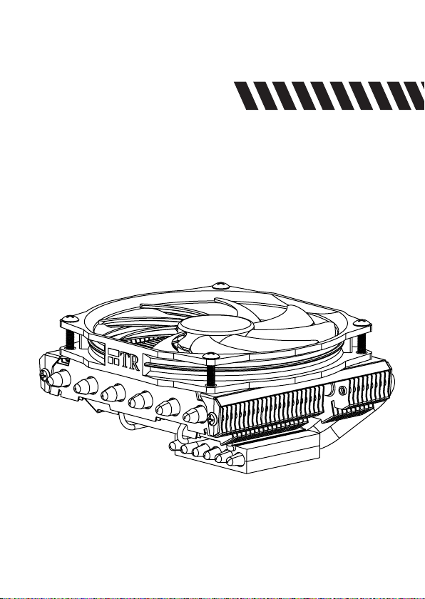
AXP-100H MUSCLE
Page 2
Page 3
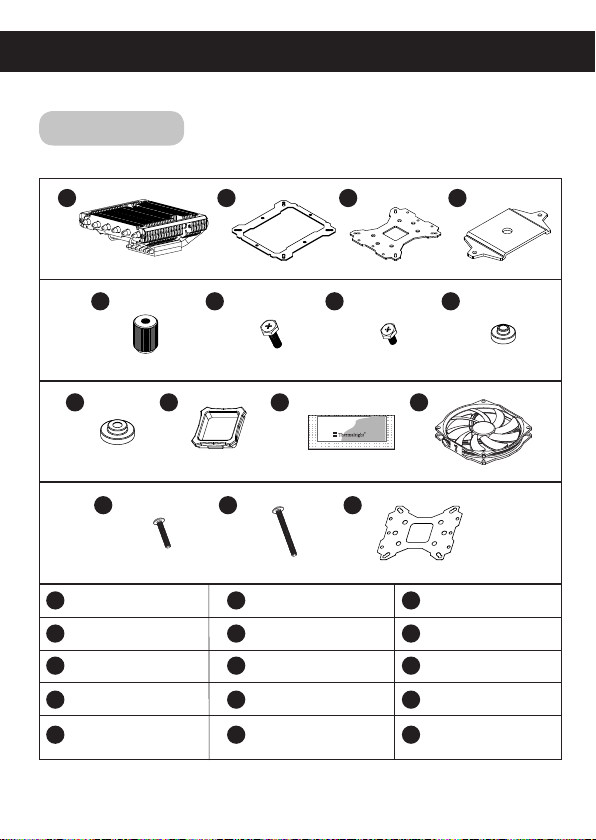
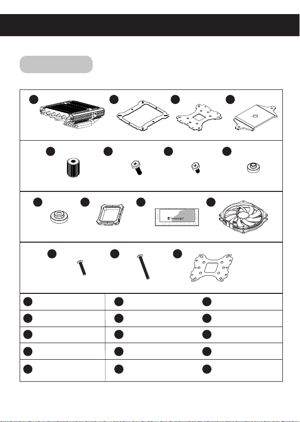
AXP-100H MUSCLE
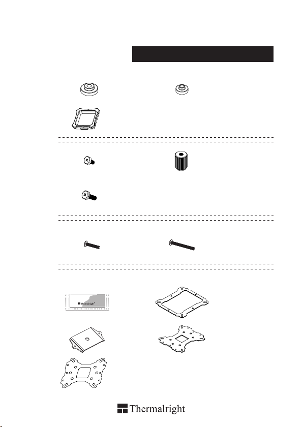
Assembly Package
Chill Factor
× 4
× 1
× 7
× 5
× 5
2g
× 1
× 1
× 4
× 4
× 5
× 1× 1
× 1
4
4
4
8
Page 4
AXP-100H MUSCLE
Intel 775/1150/1151/1155/1156/1366
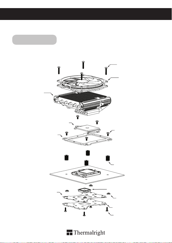
Exploded View
Important! Before proceeding with installation, please check for the most
up-to-date instructions at www.thermalright.com
Heatsink Body
Mounting Plate
Anchoring Mount
M3 L17 Screw
M3 L6 Screw
Screw Nut
TY-100BW Fan
Mylar Film
Backplate cap
Intel Washer(small)
Metal Back Plate
M3 L10 Screw
1
Page 5
Component
1
5
2 3
6
9 10
13
1
Heatsink Body ×1
Mounting Plate ×1 Screw Nut ×4
4
M3 L6 Screw ×7
7 8
Backplate Cap ×1
10
M3 L17 Screw ×5
13
14 15
2
Anchoring Mount ×1
5
Intel Washer (small) ×4
Chill Factor ×1
11
M3 L28 Screw ×5
14
7
Chill Factor
1211
2g
3
6
9
12
15
4
8
Metal Back Plate ×1
M3 L10 Screw ×5
AMD Washer (big) ×4
TY-100BW Fan×1
Mylar Film ×1
The Ultimate Cooling Solutions!
www.thermalright.com
2
Page 6
Installation Instructions:
1150
1151
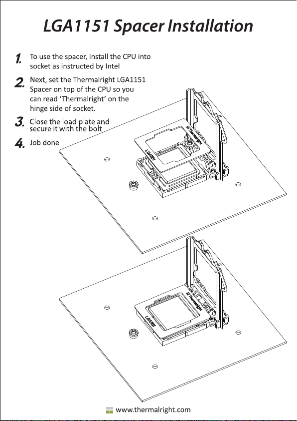
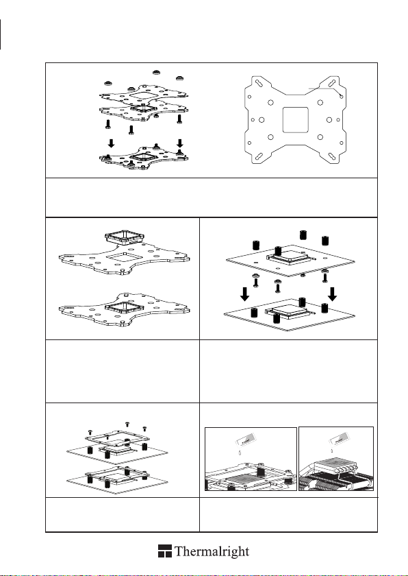
Step 1:
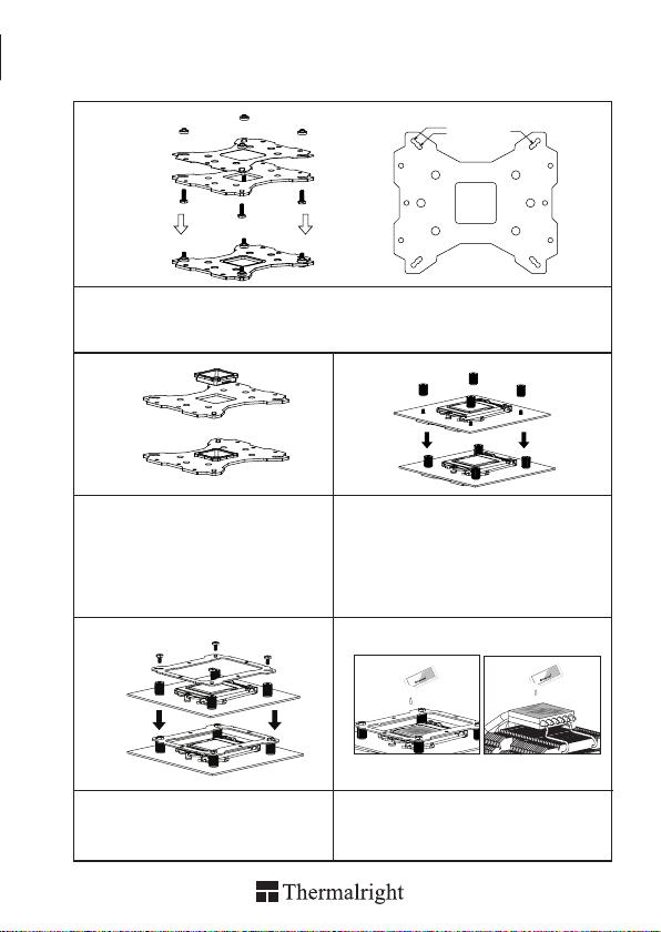
Step 1 : Backplate Installation
Choose the platform (775/1150/1151/1155/1156/1366) you are in use. Make four M3L10 Screw Pillars
go through the Metal Back Plate and the Mylar lm from bottom towards top. And then place the Metal
Back Plate on the table. Put the four Washers (for Intel) around the Screw Pillars.
Step 2:
Step 3:
1366
1155
775
1156
4
1
2
3
Step 2 : 775 Back Plate Cap
Note: When installing on a 775 platform, please
rst insert the Back Plate Cap into the opening
on the Back plate, make sure you have the Cap
facing downwards. (Only for LGA775 platform,
all other platforms go directly to Step 3.).
Step 4: Step 5:
Step 4 : Place the Anchoring Mount on the
Screw Nuts. Use the four M3L6 screws to x
the Anchoring Mount on to the Screw Nuts.
4
1
2
3
3
Step 3 : Install the four screw pillars.
Take one M3L10 screw and put one washer for
Intel around the screw pillar. Snap it through
one of holes around CPU socket from bottom
towards top. Cap the screw pillar with the screw
nut included and then tighten up. Now repeat
this installation for the other three screw pillars
in a criss-cross pattern.
or
or
g
g
t
t
2
2
c
c
a
or
or
g
g
t
t
2
2
c
c
a
a
ill F
ill F
h
h
C
C
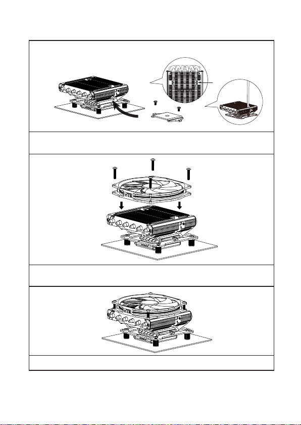
Step 5 : Applying Thermal Paste
Apply the Chill Factor to the base of the Heatsink
and the surface of the CPU evenly.
a
ill F
ill F
h
h
C
C
Page 7
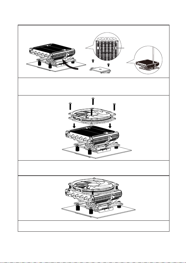
Step 6:
Step 6 : Mounting Plate Installation.
Place the Heatsink Body on top of the CPU. Make the Mounting Plate go through the Heatsink Body.
Then use the two M3L6 screws to secure the Mounting Plate.
Step 7:
Step 7 : Fan Installation
Place the included TY-100BW Fan onto the Heatsink Body. And then secure it by scewing on the
four M3L17 Screws, though the fan’s mounting hole.
Step 8:
Step 8 : Installation Completed
Plug in the fan connector to the CPU PWM Fan socket on the motherboard. Installation complete.
The Ultimate Cooling Solutions!
www.thermalright.com
4
Page 8

AXP-100H MUSCLE
AM4/AM2/AM2+/AM3/AM3+/FM1/FM2/FM2+
Exploded View
Important! Before proceeding with installation, please check for the most
up-to-date instructions at www.thermalright.com
Heatsink Body
Anchoring Mount
M3 L17 Screw
TY-100BW Fan
M3 L6 Screw
Mounting Plate
Screw Nut
5
Mylar Film
AMD Washer(big)
Backplate cap
Metal Back Plate
M3 L10 Screw
Page 9
Component
1
5
2 3
6
9 10
13
1
Heatsink Body ×1
Mounting Plate ×1 Screw Nut ×4
4
M3 L6 Screw ×7
7 8
Backplate Cap ×1
10
M3 L17 Screw ×5
13
14 15
2
Anchoring Mount ×1
5
Intel Washer (small) ×4
Chill Factor ×1
11
M3 L28 Screw ×5
14
7
Chill Factor
1211
2g
3
6
9
12
15
4
8
Metal Back Plate ×1
M3 L10 Screw ×5
AMD Washer (big) ×4
TY-100BW Fan×1
Mylar Film ×1
The Ultimate Cooling Solutions!
www.thermalright.com
6
Page 10
Installation Instructions:
Step 1:
AMD
Step 1 : Backplate Installation
Choose the platform (AMD) you are in use. Make four M3L10 Screw Pillars go through the Metal Back
Plate and the Mylar lm from bottom towards top. And then place the Metal Back Plate on the table. Put
the four Washers (for AMD) around the Screw Pillars.
Step 2: Step 3:
Step 2 : Back Plate Cap
Note: When installing on an AMD platform,
please rst insert the Back Plate Cap into the
opening on the Metal Back plate, make sure
you have the Cap facing downwards.
Step 4: Step 5:
4
1
2
3
Step 3 : Install the four screw pillars.
Take one M3L10 screw and put one washer for AMD
around the screw pillar. Snap it through one of holes
around CPU socket from bottom towards top. Cap
the screw pillar with the screw nut included and then
tighten up. Now repeat this installation for the other
three screw pillars in a criss-cross pattern.
1
or
or
g
g
t
t
2
2
c
c
a
a
ill F
ill F
h
h
C
C
4
3
2
or
or
g
g
t
t
2
2
c
c
a
a
ill F
ill F
h
h
C
C
Step 4 : Place the Anchoring Mount on the
Screw Nuts. Use the four M3L6 screws to x
the Anchoring Mount on to the Screw Nuts.
7
Step 5 : Applying Thermal Paste
Apply the Chill Factor to the base of the Heatsink
and the surface of the CPU evenly.
Page 11
Step 6:
Step 6 : Mounting Plate Installation.
Place the Heatsink Body on top of the CPU. Make the Mounting Plate go through the Heatsink Body.
Then use the two M3L6 screws to secure the Mounting Plate.
(Screwdriver goes through holes on ns)
Step 7:
Step 7 : Fan Installation
Place the included TY-100BW Fan onto the Heatsink Body. And then secure it by scewing on the four
M3L17 Screws, though the fan’s mounting hole.
Step 8:
Step 8 : Installation Completed
Plug in the fan connector to the CPU PWM Fan socket on the motherboard. Installation complete.
The Ultimate Cooling Solutions!
www.thermalright.com
8
Page 12

AXP-100H MUSCLE
Explosionszeichnung
Wichtig!
Montagehinweise auf der Webseite
Kühlkörper
Bitte prüfen Sie vor der Montage ob für Ihren Kühler aktualisierte
Intel 775/1150/1151/1155/1156/1366
www.thermalright.com
verfügbar sind.
M3 L17 Schraube
TY-100BW Lüfter
Montagerahmen
Leitschutzfolie
9
Befestigungsplatte
M3 L6 Schraube
Rändelschraube
Backplate Einsatz
Intel Unterlegscheibe (klein)
Multi Platform Backplate
M3 L10 Schraube
Page 13

Komponenten
1
5
2 3
6
9 10
13
1
Kühlkörper ×1
Befestigungsplatte ×1 Rändelschraube ×4
4
M3 L6 Schraube ×7
7 8
Backplate Einsatz x1
10
M3 L17 Schraube ×5
13
14 15
2
Montagerahmen ×1
5
Intel Unterlegscheibe
(klein)×4
Wärmeleitpaste ×1
11
M3 L28 Schraube ×5
14
7
Chill Factor
1211
2g
3
6
9
12
15
4
8
Multi Platform
Backplate x1
M3 L10 Schraube ×5
AMD Unterlegscheibe
(groß)×4
TY-100BW Lüfter×1
Leitschutzfolie
×1
The Ultimate Cooling Solutions!
www.thermalright.com
10
Page 14

Installationsanleitung :
1150
1151
Schritt 1:
Achten Sie auf die entsprechenden Intel Sockel (775/1150/1151/1155/1156/1366) vorgesehene
Bohrungen in der Multi Plattform Backplate. Führen Sie die M3L10 Schrauben jeweils von unten durch
die Backplate und die mitgelieferte Leitschutzfolie und legen dann die Backplate auf den Tisch. Legen
Sie die vier Unterlegscheiben (für Intel) über die hervorstehenden Gewinde.
Schritt 2:
Schritt 3:
1366
1155
775
1156
4
1
2
3
Beachten Sie:
Bei Verwendung einer Intel Socket 775 Plattform
setzen Sie zuerst den Backplateeinsatz in die
quadratische Öffnung der Backplate ein. Gehen
Sie sicher das der Aufsatz nach unten zeigt.
(Nur für LGA775 Plattformen)
Schritt 4: Schritt 5:
Setzen Sie den Montagerahmen auf die
Rändelschrauben. Verwenden Sie die vier
M3L6 Schrauben, um den Montagerahmen auf
den Rändelschrauben zu befestigen.
4
1
2
3
11
Legen Sie die vier Unterlegscheiben (für Intel)
über jede einzelne der vier M3L10 Schrauben.
Führen Sie diese anschließend von unten durch die
Montagelöcher des Mainboards, die sich um den
CPU Sockel herum befinden. Nun drehen Sie die
Rändelschrauben von oben auf die hervorstehenden
Gewinde und ziehen diese in diagonaler Reihenfolge
(siehe Abbildung) vorsichtig an.
or
or
g
g
t
t
2
2
c
c
a
or
or
g
g
t
t
2
2
c
c
a
a
ill F
ill F
h
h
C
C
Tragen Sie eine hauchdünne Schicht
Wärmeleitpaste auf der Oberäche der CPU und
auf der Unterseite des Kühlers auf.
a
ill F
ill F
h
h
C
C
Page 15

Schritt 6:
Platzieren Sie nun den Kühlkörper auf die CPU. Führen Sie anschließend die Befestigungsplatte durch
den Kühlkörper und benutzen die beiden M3L6 Schrauben, um die Befestigungsplatte zu befestigen.
Schritt 7:
Legen Sie den mitgelieferten TY-100BW Lüfter auf den Kühlkörper. Führen Sie die vier M3L17
Schrauben durch die Montagelöcher des Lüfters und drehen diese dann vorsichtig fest.
Schritt 8:
Verbinden Sie den Lüfterstecker mit dem CPU PWM Lüfteranschluss auf dem Mainboard.
Die Installation ist nun abgeschlossen.
The Ultimate Cooling Solutions!
www.thermalright.com
12
Page 16

AXP-100H MUSCLE
AM4/AM2/AM2+/AM3/AM3+/FM1/FM2/FM2+
Explosionszeichnung
Wichtig! Bitte prüfen Sie vor der Montage ob für Ihren Kühler aktualisierte
Montagehinweise auf der Webseite www.thermalright.com verfügbar sind.
M3 L17 Schraube
TY-100BW Lüfter
Kühlkörper
M3 L6 Schraube
Montagerahmen
Befestigungsplatte
Rändelschraube
Leitschutzfolie
13
AMD Unterlegscheibe (groß)
Backplate Einsatz
Multi Platform Backplate
M3 L10 Schraube
Page 17

Komponenten
1
5
2 3
6
9 10
13
1
Kühlkörper ×1
Befestigungsplatte ×1 Rändelschraube ×4
4
M3 L6 Schraube ×7
7 8
Backplate Einsatz x1
10
M3 L17 Schraube ×5
13
14 15
2
Montagerahmen ×1
5
Intel Unterlegscheibe
(klein)×4
Wärmeleitpaste ×1
11
M3 L28 Schraube ×5
14
7
Chill Factor
1211
2g
3
6
9
12
15
4
8
Multi Platform
Backplate x1
M3 L10 Schraube ×5
AMD Unterlegscheibe
(groß)×4
TY-100BW Lüfter×1
Leitschutzfolie
×1
The Ultimate Cooling Solutions!
www.thermalright.com
14
Page 18

Installationsanleitung:
Schritt 1:
AMD
Achten Sie auf die für den AMD Sockel vorgesehene Bohrungen in der Multi Plattform Backplate.
Führen Sie die vier M3L10 Schrauben jeweils von unten durch die Backplate und die mitgelieferte
Leitschutzfolie und legen dann die Backplate auf den Tisch. Legen Sie die vier Unterlegscheiben
(für AMD) über die hervorstehenden Gewinde.
Schritt 2: Schritt 3:
Bei Verwendung einer AMD Sockel
939 Plattform setzen Sie zuerst den
Backplateeinsatz in die quadratische Öffnung
der Backplate ein. Gehen Sie sicher, dass der
Aufsatz nach unten zeigt.
Schritt 4: Schritt 5:
4
1
2
3
Legen Sie die vier Unterlegscheiben (für AMD)
über jede einzelne der vier M3L10 Schrauben.
Führen Sie diese anschließend von unten durch die
Montagelöcher des Mainboards, die sich um den
CPU Sockel herum benden. Nun drehen Sie die
Rändelschrauben von oben auf die hervorstehenden
Gewinde und ziehen diese in diagonaler Reihenfolge
(siehe Abbildung) vorsichtig an.
or
or
g
g
t
t
2
2
c
c
a
a
ill F
ill F
h
h
C
C
4
1
2
3
or
or
g
g
t
t
2
2
c
c
a
a
ill F
ill F
h
h
C
C
Setzen Sie den Montagerahmen auf die
Rändelschrauben. Verwenden Sie die vier
M3L6 Schrauben, um den Montagerahmen
auf den Rändelschrauben zu befestigen.
15
Tragen Sie eine hauchdünne Schicht
Wärmeleitpaste auf der Oberäche der CPU und
auf der Unterseite des Kühlers auf.
Page 19

Schritt 6:
Platzieren Sie nun den Kühlkörper auf die CPU. Führen Sie anschließend die Befestigungsplatte
durch den Kühlkörper und benutzen die beiden M3L6 Schrauben, um die Befestigungsplatte zu
befestigen. Hierfür kann der Schraubendreher leicht durch die dafür vorgesehenen Aussparungen in
den Kühlnnen geführt werden.
Schritt 7:
Step 5 : Fan Installation
Legen Sie den mitgelieferten TY-100BW Lüfter auf den Kühlkörper. Führen Sie die vier M3L17
Schrauben durch die Montagelöcher des Lüfters und drehen diese dann vorsichtig fest.
Schritt 8:
Schließen Sie den Lüfterstecker an den CPU PWM Lüfteranschluss auf dem Mainboard an. Bitte prüfen
Sie die ordnungsgemäße Funktion vor der Inbetriebnahme Ihres PC. Die Installation ist abgeschlossen.
The Ultimate Cooling Solutions!
www.thermalright.com
16
Page 20

AXP-100H MUSCLE
Intel 775/1150/1151/1155/1156/1366
安裝爆炸圖
注意 ! 在您安裝前請先至官網首頁是否有最新更新安裝指南
M3 L17
螺絲
散熱器主體
Intel 墊片 ( 小 )
17
多孔扣具
壓板
TY-100BW
M3 L6
手轉螺絲
775/AMD 背蓋
塑膠絕緣片
鐵背板
M3 L10
風扇
螺絲
螺絲
Page 21

配件
1
5
2 3
6
9 10
13
1
散熱器主體 ×1
壓板 ×1 手轉螺絲 ×4
4
M3L6 螺絲 ×7
7 8
775/AMD 背蓋 ×1
10
M3 L17 螺絲 ×5
13
14 15
2
多孔扣具 ×1
5
Intel 墊片 ( 小 ) ×4
CF1 導熱膏 ×1
11
M3 L28 螺絲 ×5
14
7
Chill Factor
2g
3
6
9
12
15
4
8
1211
鐵背板 ×1
M3L10 螺絲 ×5
AMD 墊片 ( 大 ) ×4
TY-100BW
塑膠絕緣片 ×1
風扇×1
The Ultimate Cooling Solutions!
www.thermalright.com
18
Page 22

安裝步驟 :
1150
1151
步驟一 :
步驟 一 : 依照您 的處理 器類型 (775/1150/1151/1155/1156/1366) 選 擇對應 於背板的 孔位,將 四根
M3L10 螺絲穿過背板及塑膠絕緣片後套上 Intel 墊圈 ( 小 )。
1366
1155
775
1156
步驟二 :
步驟二 : 注意 !當您安裝於 775 主機板時,請
先將 775 背蓋安裝於背板上。
步驟四 : 步驟五 :
步驟四 :將多孔扣具置於手轉螺絲上,再將
M3L6 螺絲轉上多孔扣具的對應孔位。
4
1
2
3
19
步驟三 :
步驟三:將M3L10螺絲穿過Intel墊片(小),
再穿過主板中央處理器周圍的四個螺絲孔位,
然後將手轉螺絲套上穿過主板的 M3L10螺絲,
以對角線交叉方式進行 ( 左圖 )。
步驟五 : 塗抹導熱膏於散熱器銅底表面以及中央
處理器銅蓋上。
4
1
or
or
g
g
t
t
2
2
c
c
a
a
ill F
ill F
h
h
C
C
2
3
or
or
g
g
t
t
2
2
c
c
a
a
ill F
ill F
h
h
C
C
Page 23

:
步驟六
步驟六 : 將散熱器主體置放於中央處理器上,讓銅底完全覆蓋中央處理器,再將壓板放置散熱器鋁蓋
上,最後將 M3L6 螺絲鎖上壓板兩端。
:
步驟七
步驟七 : 將風扇置放於散熱器上,並使用四根 M3L17 螺絲鎖上風扇螺絲孔位,將其固定。
:
步驟八
步驟八 : 最後將風扇接頭插入主板上的 CPU FAN 插槽,安裝完成。
The Ultimate Cooling Solutions!
www.thermalright.com
20
Page 24

AXP-100H MUSCLE
AM4/AM2/AM2+/AM3/AM3+/FM1/FM2/FM2+
安裝爆炸圖
注意 ! 在您安裝前請先至官網首頁是否有最新更新安裝指南
M3 L17
螺絲
散熱器主體
21
多孔扣具
塑膠絕緣片
TY-100BW
M3 L6
螺絲
手轉螺絲
AMD墊片(大)
775/AMD 背蓋
鐵背板
M3 L10
螺絲
風扇
壓板
Page 25

配件
1
5
2 3
6
9 10
13
1
散熱器主體 ×1
壓板 ×1 手轉螺絲 ×4
4
M3L6 螺絲 ×7
7 8
775/AMD 背蓋 ×1
10
M3 L17 螺絲 ×5
13
14 15
2
多孔扣具 ×1
5
Intel 墊片 ( 小 ) ×4
CF1 導熱膏 ×1
11
M3 L28 螺絲 ×5
14
7
Chill Factor
2g
3
6
9
12
15
4
8
1211
鐵背板 ×1
M3L10 螺絲 ×5
AMD 墊片 ( 大 ) ×4
TY-100BW
塑膠絕緣片 ×1
風扇×1
The Ultimate Cooling Solutions!
www.thermalright.com
22
Page 26

安裝步驟 :
:
步驟一
步驟一 : 依照您的處理器類型選擇對應於背板的孔位,將四根 M3L10 螺絲穿過背板及塑膠絕緣片後套
上 AMD 墊圈 ( 大 )。
AMD
:
步驟二
步驟二 : 注意 ! 當您安裝於AMD 主機板時,
請先將 AMD 背蓋安裝於背板上。
:
步驟四
步驟四 :將多孔扣具置於手轉螺絲上,再將
M3L6 螺絲轉上多孔扣具的對應孔位。
4
1
2
3
23
:
步驟三
步驟三:將M3L10螺絲穿過Intel墊片(小),再穿
過主板中央處理器周圍的四個螺絲孔位,然後將手
轉螺絲套上穿過主板的 M3L10 螺絲,以對角線交
叉方式進行 ( 左圖 )。
:
步驟五
or
or
g
g
t
t
2
2
c
c
a
a
ill F
ill F
h
h
C
C
步驟五 : 塗抹導熱膏於散熱器銅底表面以及中央
處理器銅蓋上。
4
1
2
3
or
or
g
g
t
t
2
2
c
c
a
a
ill F
ill F
h
h
C
C
Page 27

:
步驟六
步驟六 : 將散熱器主體置放於中央處理器上,讓銅底完全覆蓋中央處理器,再將壓板放置散熱器鋁蓋
上,最後將 M3L6 螺絲鎖上壓板兩端。
:
步驟七
步驟七 : 將風扇置放於散熱器上,並使用四根 M3L17 螺絲鎖上風扇螺絲孔位,將其固定。
:
步驟八
步驟八 : 最後將風扇接頭插入主板上的 CPU FAN 插槽,安裝完成。
The Ultimate Cooling Solutions!
www.thermalright.com
24
Page 28

Upgrading Your Fan to 9225mm series fans
Step 1:
Step 1:Secure the fan by screwing on the four M3L28 Screws, though the fan’s mounting holes.
Step 2:
Step 2: Installation Completed.
Plug in the fan connector to the CPU PWM Fan socket on the motherboard.
25
Page 29

Upgrade auf 25 mm hohen Lüfter
Schritt 1:
Positionieren Sie den 25 mm hohen Lüfter auf den Kühlkörper und drehen anschließend die vier
mitgelieferten M3L28 Schrauben durch die Löcher im Lüfterrahmen in die dafür vorgesehenen
Montagebohrungen.
Schritt 2:
Verbinden Sie den Lüfterstecker mit dem CPU PWM Lüfteranschluss auf dem Mainboard.
Die Installation ist nun abgeschlossen.
The Ultimate Cooling Solutions!
www.thermalright.com
26
Page 30

25mm 高度風扇安裝
:
步驟一
步驟一 : 將風扇置放於散熱器上,並使用四根 M3L28 螺絲鎖上風扇螺絲孔位,將其固定。
:
步驟二
步驟二 : 最後將風扇接頭插入主板上的 CPU FAN 插槽,安裝完成。
27
Page 31

AXP-100H MUSCLE
Technical Spec
Heatsink Specifications:
Dimension: Length 119mm x Width 105mm x Height 51mm
Weight: 310g (Heatsink only)
Heatpipe: 6mm heatpipe*6 units
Fan Specification:
Dimension: L108mm x H101mm x W14mm
Weight: 40g
Fan speed: 900~2500RPM (PWM controlled)
Fan noise: 22~30 dBA MAX (Test distance 1.0M)
Airflow: 16.0~44.5CFM MAX
Connector: 4 Pin (PWM Fan connector)
The Ultimate Cooling Solutions!
www.thermalright.com
28
Page 32

AXP-100H MUSCLE
Technische Spezikationen
Kühlkörper Spezifikationen:
Maße (in mm): Länge 119 x Breite 105 x Höhe 51
Gewicht: 310 g (nur Kühlkörper)
Heatpipe: 6 mm Heatpipe * 6 Stück
Lüfter Spezifikationen:
Maße (in mm): L108 x B101 x H14
Gewicht: 40 g
Drehzahl: 900 ~ 2500 U/min +/- 10% (PWM gesteuert)
Lautstärke: 22 ~ 30dBA max. +/- 10% (Messabstand 1 m)
Förderleistung: 16 ~ 44.5 m³/h
Anschluss: 4 Pin (PWM Lüfteranschluss)
29
Page 33

AXP-100H MUSCLE
散熱器規格
散熱器規格書 :
尺寸 : 長 119mm x 105mm x 51mm
重量 :310 克 ( 本體重量 )
熱導管 :6mm 熱導管 *6 支
風扇規格書 :
尺寸 : 長 108mm x 寬 101mm x 高 14mm
重量 :40 克
風扇轉速 :900~2500RPM( 可透過 PWM 控制 )
風扇噪音 :22~30dBA MAX ( 一米測試距離 )
風量 :16.0~44.5CFM MAX
接頭類型 :4Pin PWM 接頭
The Ultimate Cooling Solutions!
www.thermalright.com
30
Page 34

AXP-100H MUSCLE
105.47
119
51.15
31
34.15
26.15
39.15
26.15
22.3
42
9.43
27.02
40
Page 35

Page 36

The Ultimate Cooling Solutions!
www.thermalright.com
TEL: +886-2-2915-5005
FAX: +886-2-2915-5123
EMAIL: sales@thermalright.com
 Loading...