

Page 1
Thermalright
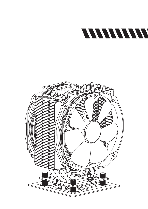
Archon SB-E X2
Page 2

Page 3
Archon SB-E X2
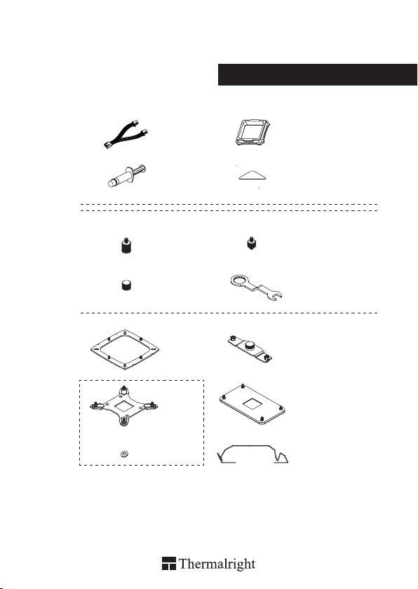
Assembly package
× 1
× 1
× 4
× 4
× 1
× 1 × 1
× 4
× 1
× 8
× 4
× 1
× 1
× 4
4
4
8
Page 4
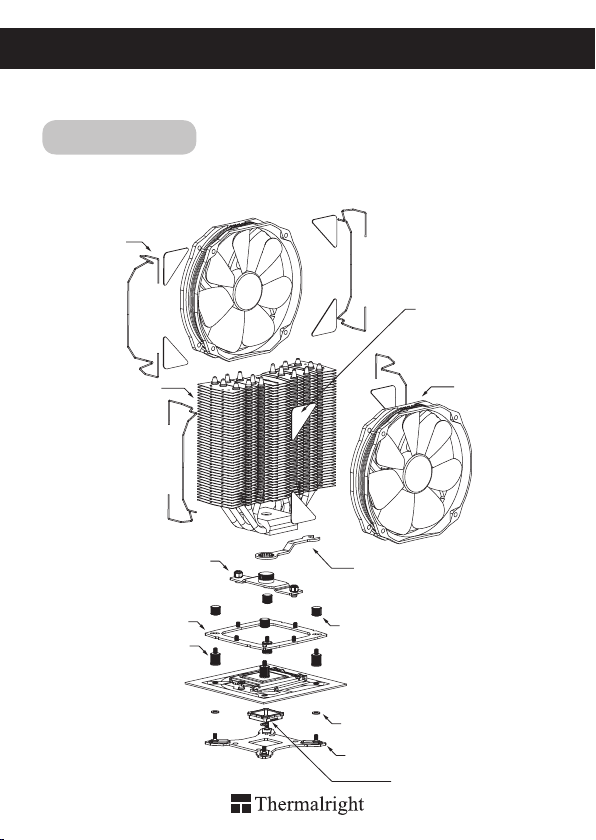
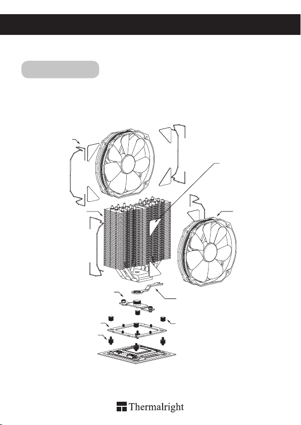
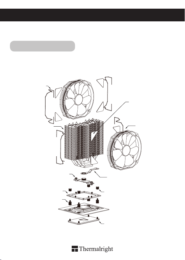
Thermalright Archon SB-E X2
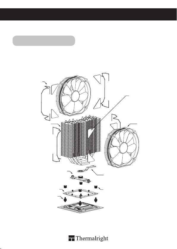
Exploded view
Important! Before proceeding with installation, please check for the most
up-to-date instructions at www.thermalright.com
Fan Clip
Intel 775/1155/1156/1366
Anti Vibration Pads
Heatsink Body
Pressure Adjustable
Mounting Plate
Anchoring Bracket Mount
Screw Pillar
1
TY141 Fan
Angled Wrench
Thumbscrew Cap
White Plastic Washer
Intel Multiple Support Backplate
Backplate cap
Page 5
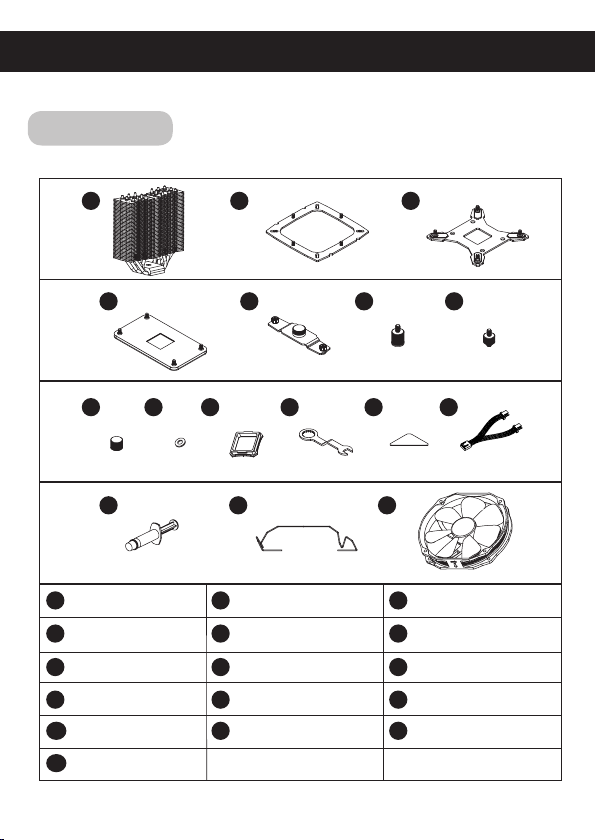
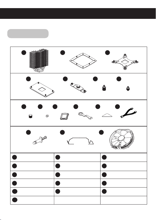
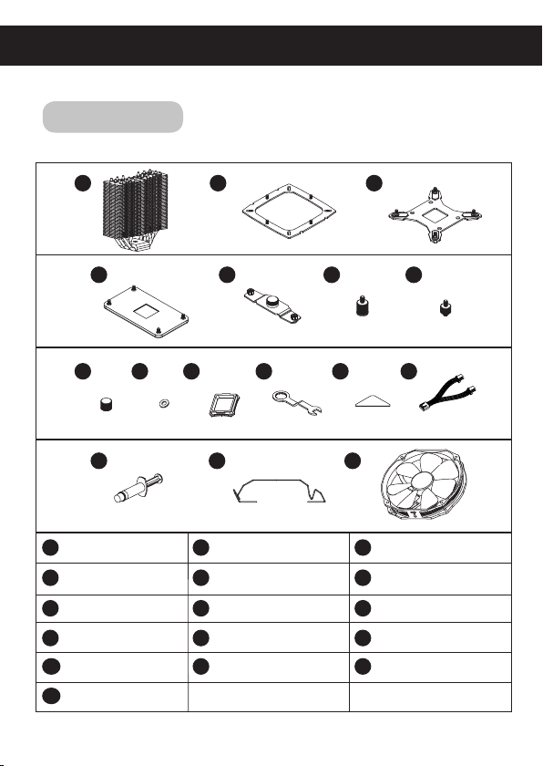
Component
1
4
8
Heatsink Body ×1
1
AMD Backplate ×1
4
LGA2011 Screw Pillar
7 8
Type C
Backplate Cap
10 11
PWM Y-cable ×1
13
TY141 Fan ×2
16
9
10 12 13
×4
×1
2
5
11
15 1614
Anchoring Bracket
2
Mount ×1
Pressure Adjustable
5
Mounting Plate
Thumbscrew Cap
Angled Wrench
Thermal Paste ×1
3
6
×1
×4
x1
12
1514
7
Intel Multiple Support
3
Backplate
Screw Pillar
6
White Plastic Washer
9
Anti Vibration Pad ×8
Fan Clip ×4
×1
×4
×4
The Ultimate Cooling Solutions!
www.thermalright.com
2
Page 6
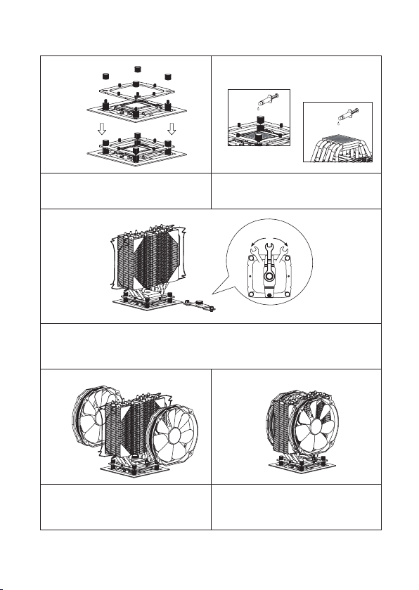
Installation Instructions:
Step 1:
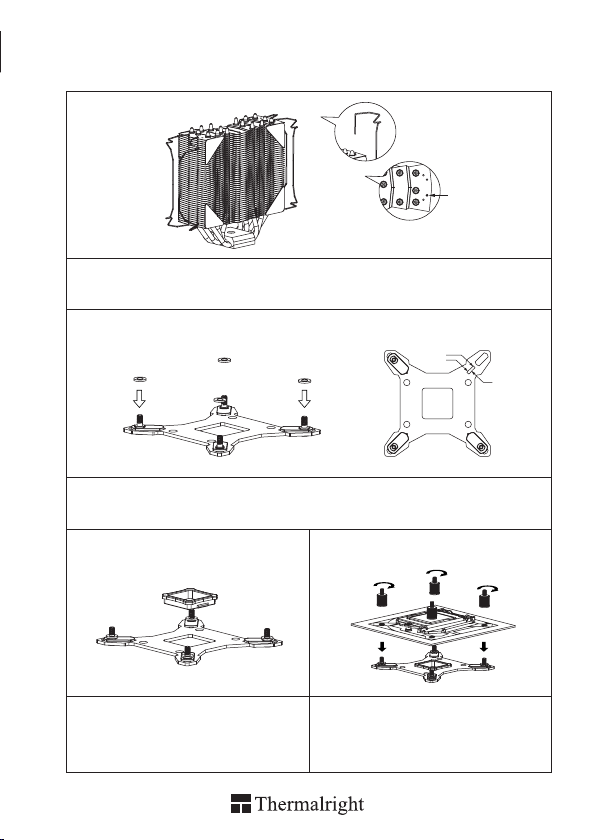
Step 1 : Part Installation
Apply the Anti-Vibration Pads to each corner of the Heatsink Body. Then pull the long end of the Fan
Clips and make it go through the bottom side hole closest to the edge as shown in the close-up diagram.
Repeat this with the top hole.
Step 2:
1366
775
Step 2 : Backplate Installation
Choose the correct Backplate according to your system (Intel), and adjust the Screw Cylinders according
to your platform. Place the four white washers through the protruding screws.
Step 3: Step 4:
1156
1155
Step 3 : Backplate Cap
Use the Backplate Cap only for the 775 platform.
3
Step 4 : Pass the Backplate through mounting
holes on the mainboard, then t the Screw Pillars
to the Backplate screws.
Page 7
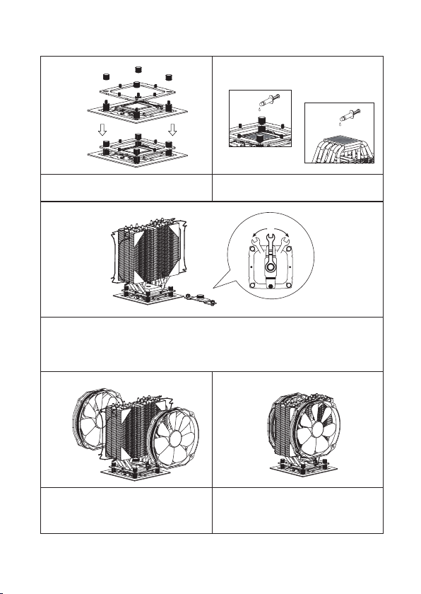
Step 5: Step 6:
Step 5 : Place the Anchoring Bracket Mount on
top of the four Screw Pillars. Tighten the 4 Screw
Pillars with the Thumbscrew Caps.
Step 7:
Step 7 : Mounting Plate
Fit the heatsink then secure it by placing the Pressure Adjustable Mounting Plate, and tighten the
hexagonal screws to the Anchoring Bracket Mount.
Tighten the central knob on the Pressure Adjustable Mounting Plate with the Angled Wrench as seen
t. (The central knob can add an addition 30lbs of force to the cooler, each half rotation adds 10 lbs of
force for a total of 70lbs)
Step 6 : Applying Thermal Paste
Apply the Thermal Paste to the base of the
Heatsink and the surface of the CPU evenly.
1/2 rotation
(+10 lb.)(-10 lb.)
Step 8: Step 9:
Step 8 : Fan Installation
Place the included TY-141 fan onto the Heatsink
Body. And then secure it with the TY-141 Fan
Clips, by pulling the Fan Clips to place the four
ends at the four holes on the TY-141 Fan.
The Ultimate Cooling Solutions!
Step 9 : Installation completed
Connect the two TY-141 fans to the PWM Y-Cable
then connect the cable to the CPU PWM Fan
socket on the motherboard. Installation complete.
www.thermalright.com
4
Page 8
Thermalright Archon SB-E X2
Exploded view
Important! Before proceeding with installation, please check for the most
up-to-date instructions at www.thermalright.com
Fan Clip
Intel LGA 2011
Anti Vibration Pads
Heatsink Body
Pressure Adjustable
Mounting Plate
Anchoring Bracket Mount
LGA2011 Screw
Pillar Type C
5
TY141 Fan
Angled Wrench
Thumbscrew Cap
Page 9

Component
1
4
8
Heatsink Body ×1
1
AMD Backplate ×1
4
LGA2011 Screw Pillar
7 8
Type C
Backplate Cap
10 11
PWM Y-cable ×1
13
TY141 Fan ×2
16
9
10 12 13
×4
×1
2
5
11
15 1614
Anchoring Bracket
2
Mount ×1
Pressure Adjustable
5
Mounting Plate
Thumbscrew Cap
Angled Wrench
Thermal Paste ×1
3
6
×1
×4
x1
12
1514
7
Intel Multiple Support
3
Backplate
Screw Pillar
6
White Plastic Washer
9
Anti Vibration Pad ×8
Fan Clip ×4
×1
×4
×4
The Ultimate Cooling Solutions!
www.thermalright.com
6
Page 10

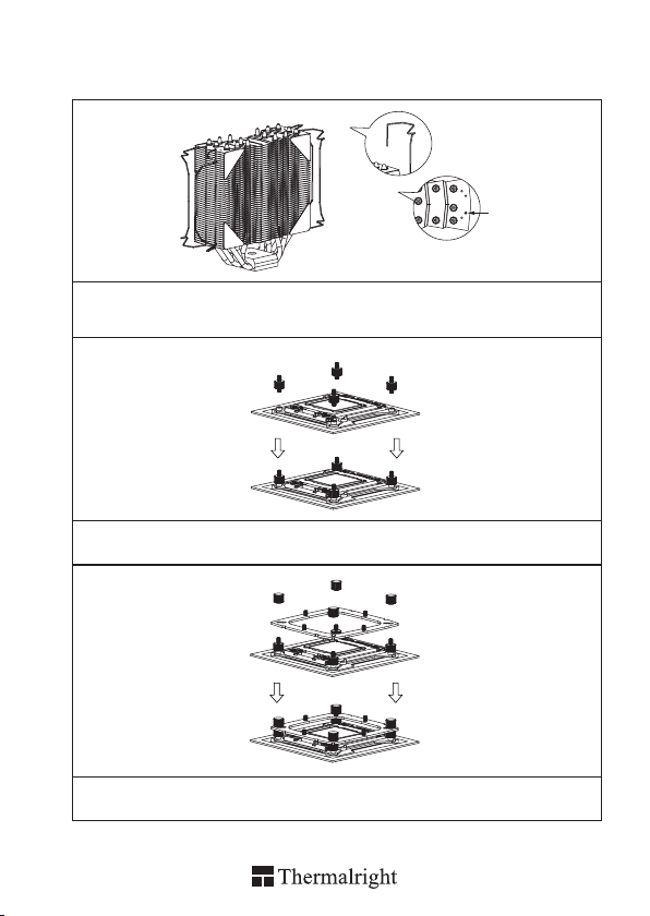
Installation Instructions:
Step 1:
Step 1 : Part Installation
Apply the Anti-Vibration Pads to each corner of the Heatsink Body. Then pull the long end of the Fan
Clips and make it go through the bottom side hole closest to the edge as shown in the close-up diagram.
Repeat this with the top hole.
Step 2:
Step 2 : Screw Pillar Installation
Screw on the 4 LGA2011 Type C Screw Pillars into the heatsink studs on the Intel ILM Assembly Frame
around the processor socket.
Step 3:
Step 3 : Anchoring Mount Installation
Place the Anchoring Bracket Mount on top of the 4 LGA2011 Type C Screw Pillars. Then tighten the 4
LGA2011 Type C Screw Pillars with the Thumbscrew Caps.
7
Page 11

Thermalright Archon SB-E X2
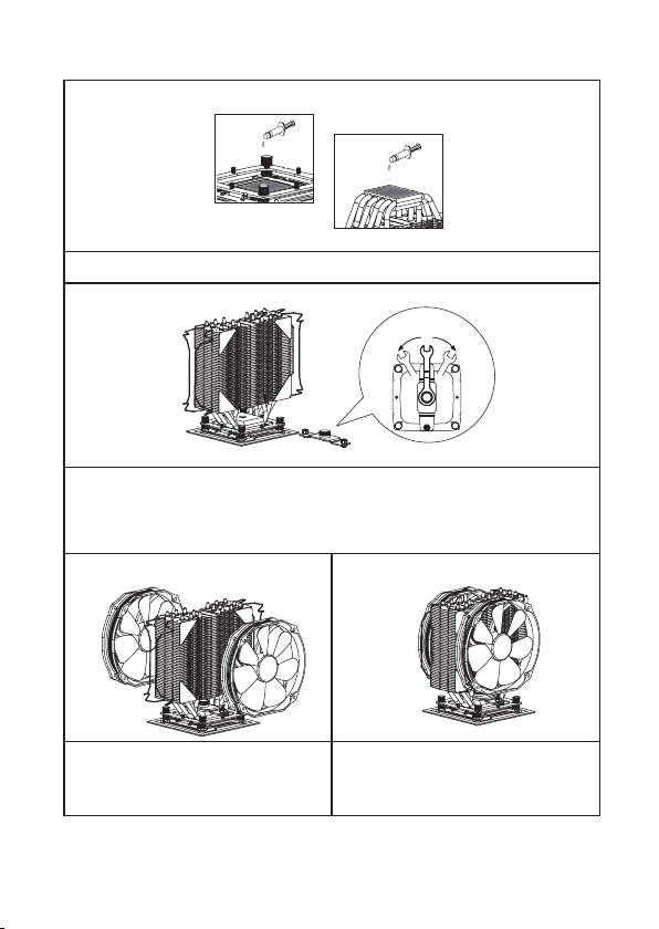
Step 4:
Step 4 : Applying Thermal Paste
Apply the Thermal Paste to the base of the Heatsink and the surface of the CPU evenly.
Step 5:
Step 5 : Mounting Plate
Fit the heatsink then secure it by placing the Pressure Adjustable Mounting Plate, and tighten the
hexagonal screws to the Anchoring Bracket Mount.
Tighten the central knob on the Pressure Adjustable Mounting Plate with the Angled Wrench as seen
t. (The central knob can add an addition 30lbs of force to the cooler, each half rotation adds 10 lbs of
force for a total of 70lbs)
Step 6: Step 7:
1/2 rotation
(+10 lb.)(-10 lb.)
Step 6 : Fan Installation
Place the included TY-141 fan onto the Heatsink
Body. And then secure it with the TY-141 Fan
Clips, by pulling the Fan Clips to place
the four ends at the four holes on the TY-141 Fan.
Step 7 : Installation completed
Connect the two TY-141 fans to the PWM Y-Cable
then connect the cable to the CPU PWM Fan
socket on the motherboard. Installation complete.
The Ultimate Cooling Solutions!
www.thermalright.com
8
Page 12

Thermalright Archon SB-E X2
AM2/AM2+/AM3/AM3+/FM1/FM2
Exploded view
Important! Before proceeding with installation, please check for the most
up-to-date instructions at www.thermalright.com
Fan Clip
Anti Vibration Pads
Heatsink Body
Pressure Adjustable
Mounting Plate
Anchoring Bracket Mount
Screw Pillar
9
TY141 Fan
Angled Wrench
Thumbscrew Cap
AMD Backplate
Page 13

Component
1
4
8
Heatsink Body ×1
1
AMD Backplate ×1
4
LGA2011 Screw Pillar
7 8
Type C
Backplate Cap
10 11
PWM Y-cable ×1
13
TY141 Fan ×2
16
9
10 12 13
×4
×1
2
5
11
15 1614
Anchoring Bracket
2
Mount ×1
Pressure Adjustable
5
Mounting Plate
Thumbscrew Cap
Angled Wrench
Thermal Paste ×1
3
6
×1
×4
x1
12
1514
7
Intel Multiple Support
3
Backplate
Screw Pillar
6
White Plastic Washer
9
Anti Vibration Pad ×8
Fan Clip ×4
×1
×4
×4
The Ultimate Cooling Solutions!
www.thermalright.com
10
Page 14

Installation Instructions:
Step 1:
Step 1 : Part Installation
Apply the Anti-Vibration Pads to each corner of the heatsink. Then pull the long end of the Fan Clips
and make it go through the bottom side hole closest to the edge as shown in the close-up diagram.
Repeat this with the top hole.
Step 2:
Step 2 : Backplate Installation
Choose the correct Backplate according to your system (AMD). Pass the Backplate through mounting
holes on the mainboard, then t the Screw Pillars to the Backplate screws.
Step 3:
Step 3 : Backplate Cap
Place the Anchoring Bracket Mount on top of the four Screw Pillars. Tighten the 4 Screw Pillars with the
Thumbscrew Caps.
11
Page 15

Step 4:
Step 4 : Anchoring Mount Installation
Place the Anchoring Mount on the Screw Nuts. Use the four M3L6 Screws to x the Anchoring Mount
on to the Screw Nuts.
Step 5:
Step 5 : Mounting Plate
Fit the heatsink then secure it by placing the Pressure Adjustable Mounting Plate, and tighten the
hexagonal screws to the Anchoring Bracket Mount.
Tighten the central knob on the Pressure Adjustable Mounting Plate with the Angled Wrench as seen
t. (The central knob can add an addition 30lbs of force to the cooler, each half rotation adds 10 lbs of
force for a total of 70lbs)
1/2 rotation
(+10 lb.)(-10 lb.)
Step 6: Step 7:
Step 6 : Fan Installation
Place the included TY-141 fan onto the
Heatsink Body. And then secure it with the TY141 Fan Clips, by pulling the Fan Clips to place
the four ends at the four holes on the TY-141 Fan.
Step 7 : Installation completed
Connect the two TY-141 fans to the PWM Y-Cable
then connect the cable to the CPU PWM Fan
socket on the motherboard. Installation complete.
The Ultimate Cooling Solutions!
www.thermalright.com
12
Page 16

Thermalright Archon SB-E X2
Intel 775/1155/1156/1366
Explosionszeichnung
Important! Bitte prüfen Sie vor der Montage, ob es für Ihren Kühler aktualisierte
Montagehinweise auf der Webseite www.thermalright.com verfügbar sind.
Lüfterklammer
Anti-Vibrationspad
Kühlkörper
Anpressdruckjustierungs
platte
Montagerahmen
Adapterschraube
13
TY141 Lüfter
gekröpfter Vielzahnschlüssel
Rändelmutter
weiße Unterlegscheibe
Intel Multiplattform Backplate
Backplateeinsatz
Page 17
Komponenten
1
4
8
Kühlkörper ×1
1
AMD Backplate ×1
4
LGA2011 Adapter-
7 8
schraube Type C ×4
Backplateeinsatz ×1
10 11
PWM Y-Kabel ×1
13
TY141 Lüfter ×2
16
9
10 12 13
2
5
11
15 1614
2
Montagerahmen ×1
Anpressdruck
5
justierungsplatte ×1
Rändelmutter ×4
gekröpfter Vielzahnschlüssel ×1
Wärmeleitpaste ×1
3
6
12
1514
7
Intel Multiplattform
3
Backplate ×1
Adapterschraube ×4
6
weiße Unterlegscheibe
9
×4
Anti-Vibrationspad ×8
Lüfterklammer×4
The Ultimate Cooling Solutions!
www.thermalright.com
14
Page 18

Installationsanleitung:
Schritt 1:
Bringen Sie die vier selbstklebenden Anti-Vibrationspads an den Ecken des Kühlkörpers an. Danach
führen Sie zuerst das untere Ende der Lüfterklammer in das äußere Loch an der Lamellenunterseite
(siehe Abbildung). Wiederholen Sie anschließend den Vorgang an der Oberseite.
Schritt 2:
1366
775
Achten Sie auf die für Ihr System entsprechend vorgesehene Bohrungen (Intel Sockel
775/1155/1156/1366) in der Multi Plattform Backplate. Führen Sie die vier Schraubenzylinder jeweils
von unten durch diese
Bohrungen. Legen Sie die vier Unterlegscheiben (für Intel) über die hervorstehenden Gewinde.
Schritt 3: Schritt 4:
1156
1155
Bei Verwendung einer Intel Sockel 775 Plattform
setzen Sie zuerst den Backplate Aufsatz in die
quadratische Öffnung der Backplate ein. Gehen
Sie sicher, dass der Aufsatz nach unten zeigt.
15
Platzieren Sie das Mainboard von oben auf die
Backplate, so dass die hervorstehenden
Schraubengewinde durch die Löcher um den
Prozessorsockel gehen. Schrauben Sie die
beiliegenden Rändelschrauben auf die vier
Schraubengewinde.
Page 19
Schritt 5: Schritt 6:
Setzen Sie den Montagerahmen auf die vier
Schraubenzylinder. Verwenden Sie die vier
Rändelmuttern, um den Montagerahmen auf den
Adapterschrauben zu befestigen.
Schritt 7:
Platzieren Sie den Kühlkörper auf den Montagerahmen und sichern ihn mit der
Anpressdruckjustierungsplatte, indem Sie diese mit den beiden Sechskantschrauben verschrauben.
Ziehen Sie die zentrale Einstellschraube mit dem gekröpften Vielzahnschlüssel bis zum gewünschten
Anpressdruck an. (Über dieEinstellschraube lassen sich bis zu 30 lbs Anpressdruck auf den Kühler
ausüben. Jede halbe Umdrehung erhöht den Druck um 10 lbs, maximal bis zu 70 lbs.)
Tragen Sie eine hauchdünne Schicht
Wärmeleitpaste auf der Oberfläche der CPU
und auf der Unterseite des Kühlers auf.
1/2 Umdrehung
(+10 lb.)(-10 lb.)
Schritt 8: Schritt 9:
Positionieren Sie die beiden TY 141 Lüfter
auf dem Kühlkörper und befestigen Sie diese
mit den Lüfterklammern, indem Sie die Ecken
paarweise in die vier Montagelöcher ziehen.
The Ultimate Cooling Solutions!
Verbinden Sie die beiden TY-141 Lüfter mit den
PWM Y-Kabel und schließen Sie das Kabel nun
an den CPU PWM Lüfteranschluss auf dem
Mainboard an. Die Installation ist abgeschlossen.
www.thermalright.com
16
Page 20
Thermalright Archon SB-E X2
Explosionszeichnung
Wichtig! Bitte prüfen Sie vor der Montage, ob es für Ihren Kühler aktualisierte
Montagehinweise auf der Webseite www.thermalright.com verfügbar sind.
Lüfterklammer
Intel LGA 2011
Anti-Vibrationspad
Kühlkörper
Anpressdruckjustierungsplatte
Anchoring Bracket Mount
LGA2011 Screw
Pillar Type C
17
TY141 Lüfter
gekröpfter Vielzahnschlüssel
Rändelmutter
Page 21

Komponenten
1
4
8
Kühlkörper ×1
1
AMD Backplate ×1
4
LGA2011 Adapter-
7 8
schraube Type C ×4
Backplateeinsatz ×1
10 11
PWM Y-Kabel ×1
13
TY141 Lüfter ×2
16
9
10 12 13
2
5
11
15 1614
2
Montagerahmen ×1
Anpressdruck
5
justierungsplatte ×1
Rändelmutter ×4
gekröpfter Vielzahnschlüssel ×1
Wärmeleitpaste ×1
3
6
12
1514
7
Intel Multiplattform
3
Backplate ×1
Adapterschraube ×4
6
weiße Unterlegscheibe
9
×4
Anti-Vibrationspad ×8
Lüfterklammer×4
The Ultimate Cooling Solutions!
www.thermalright.com
18
Page 22
Installationsanleitung:
Schritt 1:
Bringen Sie die vier selbstklebenden Anti-Vibrationspads an den Ecken des Kühlkörpers an. Danach
führen Sie zuerst das untere Ende der Lüfterklammer in das äußere Loch an der Lamellenunterseite
(siehe Abbildung). Wiederholen Sie anschließend den Vorgang an der Oberseite.
Schritt 2:
Schrauben Sie die vier LGA2011 Typ C Adapterschrauben in die Gewindebolzen auf dem Intel ILM
Montagerahmen, der sich um den Prozessorsockel bendet.
Schritt 3:
Setzen Sie den Montagerahmen auf die vier LGA2011 Typ C Adapterschrauben. Anschließend xieren
Sie die vier LGA2011 Typ C Adapterschrauben mit den Rändelmuttern.
19
Page 23
Thermalright Archon SB-E X2
Schritt 4:
Tragen Sie eine hauchdünne Schicht Wärmeleitpaste auf der Oberäche der CPU und auf der Unterseite
des Kühlers auf.
Schritt 5:
Platzieren Sie den Kühlkörper auf den Montagerahmen und sichern ihn mit der
Anpressdruckjustierungsplatte,
indem Sie diese mit den beiden Sechskantschrauben verschrauben. Ziehen Sie die zentrale
Einstellschraube mit dem gekröpften Vielzahnschlüssel bis zum gewünschten Anpressdruck an. (Über
die Einstellschraube lassen sich bis zu 30 lbs Anpressdruck auf den Kühler ausüben. Jede halbe
Umdrehung erhöht den Druck um 10 lbs, maximal bis zu 70 lbs.)
Schritt 6: Schritt 7:
1/2 Umdrehung
(+10 lb.)(-10 lb.)
Positionieren Sie die beiden TY 141 Lüfter
auf dem Kühlkörper und befestigen Sie diese
mit den Lüfterklammern, indem Sie die Ecken
paarweise in die vier Montagelöcher ziehen.
Verbinden Sie die beiden TY-141 Lüfter mit dem
PWM Y-Kabel und schließen Sie das Kabel nun
an den CPU PWM Lüfteranschluss auf dem
Mainboard an. Die Installation ist abgeschlossen.
The Ultimate Cooling Solutions!
www.thermalright.com
20
Page 24
Thermalright Archon SB-E X2
AM2/AM2+/AM3/AM3+/FM1/FM2
Explosionszeichnung
Wichtig! Bitte prüfen Sie vor der Montage, ob es für Ihren Kühler aktualisierte
Montagehinweise auf der Webseite www.thermalright.com verfügbar sind.
Lüfterklammer
Anti-Vibrationspad
21
Kühlkörper
Anpressdruckjustierungsplatte
Montagerahmen
Adapterschraube
TY141 Lüfter
gekröpfter Vielzahnschlüssel
Rändelmutter
AMD Backplate
Page 25
Komponenten
1
4
8
Kühlkörper ×1
1
AMD Backplate ×1
4
LGA2011 Adapter-
7 8
schraube Type C ×4
Backplateeinsatz ×1
10 11
PWM Y-Kabel ×1
13
TY141 Lüfter ×2
16
9
10 12 13
2
5
11
15 1614
2
Montagerahmen ×1
Anpressdruck
5
justierungsplatte ×1
Rändelmutter ×4
gekröpfter Vielzahnschlüssel ×1
Wärmeleitpaste ×1
3
6
12
1514
7
Intel Multiplattform
3
Backplate ×1
Adapterschraube ×4
6
weiße Unterlegscheibe
9
×4
Anti-Vibrationspad ×8
Lüfterklammer×4
The Ultimate Cooling Solutions!
www.thermalright.com
22
Page 26

Installationsanleitung:
Schritt 1:
Bringen Sie die vier selbstklebenden Anti-Vibrationspads an den Ecken des Kühlkörpers an. Danach
führen Sie zuerst das untere Ende der Lüfterklammer in das äußere Loch an der Lamellenunterseite
(siehe Abbildung). Wiederholen Sie anschließend den Vorgang an der Oberseite.
Schritt 2:
Nehmen Sie die Backplate für Ihr AMD System. Legen Sie diese von unten an Ihr Mainboard an, so dass
die Gewindebolzen durch die Befestigungslöcher des Mainboards gehen. Schrauben Sie nun die
Adapterschrauben von oben in die Gewindebolzen.
Schritt 3:
Setzen Sie den Montagerahmen auf die vier Schraubenzylinder. Verwenden Sie die vier Rändelmuttern,
um den Montagerahmen auf den Adapterschrauben zu befestigen.
23
Page 27

Schritt 4:
Tragen Sie eine hauchdünne Schicht Wärmeleitpaste auf der Oberfläche der CPU und auf der
Unterseite des Kühlers auf.
Schritt 5:
Platzieren Sie den Kühlkörper auf den Montagerahmen und sichern ihn mit der
Anpressdruckjustierungsplatte, indem Sie diese mit den beiden Sechskantschrauben verschrauben.
Ziehen Sie die zentrale Einstellschraube mit dem gekröpften Vielzahnschlüssel bis zum gewünschten
Anpressdruck an. (Über die Einstellschraube lassen sich bis zu 30 lbs Anpressdruck auf den Kühler
ausüben. Jede halbe Umdrehung erhöht den Druck um 10 lbs, maximal bis zu 70 lbs.)
1/2 Umdrehung
(+10 lb.)(-10 lb.)
Schritt 6: Schritt 7:
Positionieren Sie die beiden TY 141 Lüfter
auf dem Kühlkörper und befestigen Sie diese
mit den Lüfterklammern, indem Sie die Ecken
paarweise in die vier Montagelöcher ziehen.
The Ultimate Cooling Solutions!
Verbinden Sie die beiden TY-141 Lüfter mit dem
PWM Y-Kabel und schließen Sie das Kabel nun
an den CPU PWM Lüfteranschluss auf dem
Mainboard an. Die Installation ist abgeschlossen.
www.thermalright.com
24
Page 28

Thermalright Archon SB-E X2
Technical Spec
Heatsink Specifications:
Dimension: Length 155mm x Width 53.66mm x Height 170.2mm
Weight: 777g (Heatsink only)
Heatpipe: 6mm heatpipe*8 units
Copper Base: C1100 Pure copper nickel plated
Fan Specification:
Dimension: L152mm x H140mm x W26.5m
Weight: 175g
Fan speed: 900~1300RPM (PWM controlled)
Fan noise: 21~25dBA MAX
Airflow: 28.32~73.64CFM MAX
Connector: 4 Pin (PWM Fan connector)
25
Page 29

Thermalright Archon SB-E X2
155
53.66
40 57.5
170.2
34.45
53
The Ultimate Cooling Solutions!
www.thermalright.com
26
Page 30

Thermalright -- Endorsed by Critics, Chosen by Experts
Page 31

Page 32

The Ultimate Cooling Solutions!
www.thermalright.com
TEL: +886-2-8663-6630
FAX: +886-2-8663-6645
EMAIL: sales@thermalright.com
 Loading...