

Thermal Engineering 4054M Installation Manual
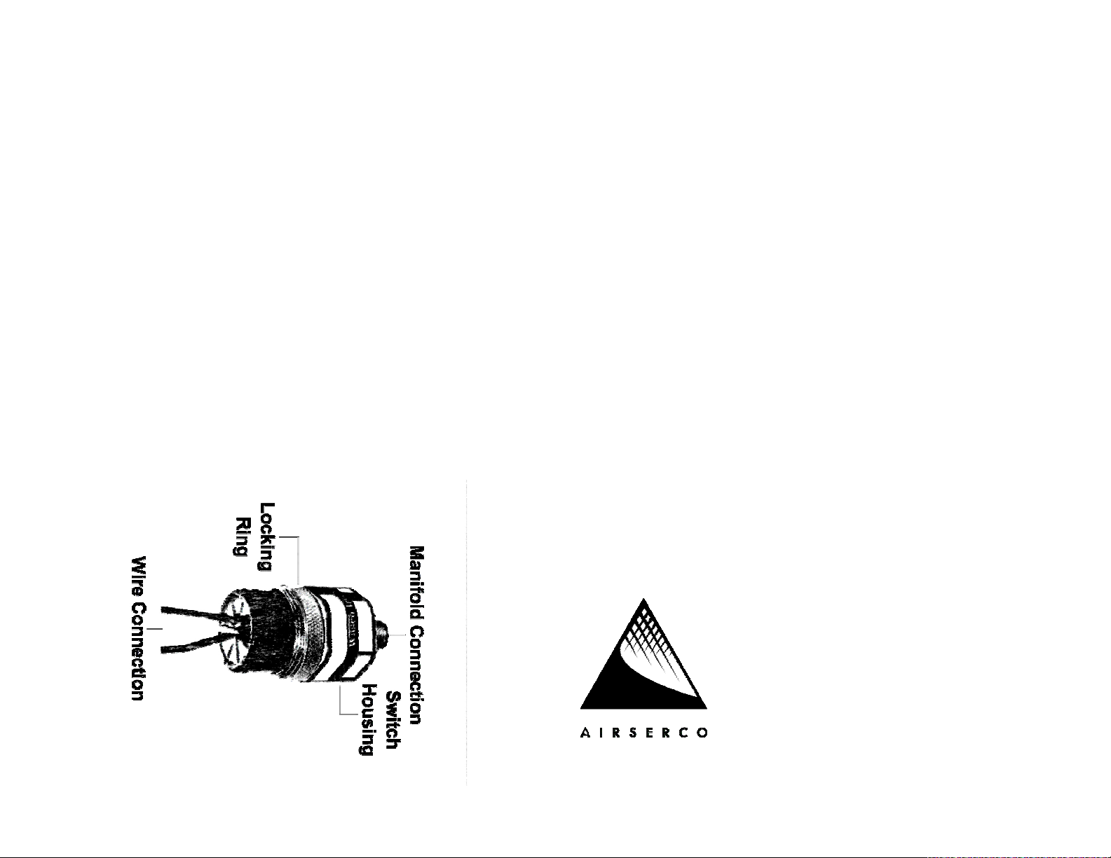
These instructions are based on viewing the pressure
switch with the manifold connection at the top and the
wire connection at that bottom. IMPORTANT: The
pressure switch is very sensitive and all adjustments
should be made in small increments. Loosen the outer
lock ring slightly. To decrease the pressure setting, turn
the switch housing clockwise (to your right.) To increase
the pressure, turn the switch housing counterclockwise
(to your left). Again, the switch is extremely sensitive,
each one (1) degree of rotation equals approximately one
(1) pound change in pressure and turning the switch as
little as 1/4 turn (90 degrees) can take the switch out of
it's range of 450 PSI. It is best to make small changes of
3-4 degrees to reach the desired setting. With the switch
powered, pressurize the switch to the desired pressure
and adjust the switch housing in small steps. By
watching for the pilot light to go out, you can adjust the
setting to very exacting pressures. Be sure to tighten the
lock ring immediately after setting the switch.
4054M
Adjusting the Pressure Switch
125 lb.
Refrigerant
Cylinder
Heater
INSTRUCTIONS
Revised 11/15/04
Airserco Manufacturing Company
7555 Tyler Boulevard
Mentor, OH 44060 U.S.A.
(440) 946-2700 FAX (440) 946-8188
www.airserco.com

4054M Cylinder Heater
The 4054M Cylinder Heater is designed for use on 125
lb. refrigerant cylinders (approx. 10-11 inches in
diameter and 54 inches tall) and consists of three basic
components:
1.) CP4054 Manifold. Manifold with pressure
control, power cords, valve and hose.
2.) CP4054-3A Element. 12" X 28" silicone
rubber heating element with cord and molded
thermostat.
3.) CP4054-5A Cover. Insulated wrap with Velcro
closure.
INSTALLATION AND USE
1.) Attach the manifold to the liquid valve of the
cylinder using the 3/4 inch nut on the manifold. After the
nut has been tightened, loop the safety chain on the
manifold's electrical box over the neck of the containers
liquid valve. Hook the 'S'- hook on the chain back
through the eye on the electrical box. This is important
to prevent any strain on the manifolds electrical
connections.
2.) Secure the heating element to the cylinder. With
the molded thermostat facing out and the molded cord
pointing downward, wrap the heating element around
the cylinder at its base. Pull the Velcro straps tight so
the element is secure with the area behind the
thermostat in contact with the surface of the cylinder.
Connect the male plug on the elements cord to the
short female connector on the manifolds electrical box.
INSTALLATION AND USE (Cont'd)
3.) Connect the charging hose to the 1/4" flare end of the
ball valve on the manifold. Make sure the valve is closed.
Connect the other end of the hose to the container or
device to receive the refrigerant from the 125 lb. cylinder.
Open the liquid valve on the cylinder. Connect the
manifold's power supply cord to a standard 115VAC
outlet (or timer switch). The heating element will begin to
heat and is now operating under the control of the
manifold's pressure switch. The pressure is preset at
160-165 PSIG, but is easily field adjusted. To adjust or
change the pressure setting, see the diagram on the back
of this page.
4.) Wrap the insulated cover around the container. The
foil side should be against the cylinder with the white
outer layer outside and the black bound edges running
vertically. Press the Velcro tab closed. It is best to align
the cover so that a part of the thermostat is visible at the
seam to provide air circulation. The thermostat is set to
trip at 133º F and acts as a safety device backing up the
primary control, the pressure switch.
5.) When you want the refrigerant to flow, open the 1/4"
ball valve on the manifold. The pressure developed by
heating the 125 lb. cylinder will force the refrigerant under
pressure to the vessel or device connected to the valve.
DO NOT OPERATE THE HEATER WITH THE TANKS
LIQUID VALVE CLOSED. THE VALVE MUST BE OPEN
TO ALLOW THE PRESSURE SWITCH TO OPERATE
PROPERLY. USE ONLY THE MANIFOLD'S BALL
VALVE TO CONTROL REFRIGERANT FLOW.
 Loading...