

Page 1

Instruction Manual for Swimming Pool Heater
ZENITH RANGE
96kW, 120kW, 144kW & 168kW
Meddings Thermalec Ltd.
Kingsley Close, East Way, Lee Mill Industrial Estate,
Ivybridge, Devon, PL21 9LL, United Kingdom
Tel: 01752 313343 Fax: 01752 313353
[email protected] www.thermalec.co.uk
Page 2

Zenith Range Instruction
Manual
Page i
Contents
Preface ........................................................................................................................................ ii
List of illustrations and drawings .............................................................................................. iii
Pictograms used in this manual ................................................................................................ iv
1. GENERAL ....................................................................................................... 1
Heater construction .................................................................................................................... 2
Heater operation ......................................................................................................................... 5
Heater technical details ................................................................................................ .............. 5
Standards ................................................................................................................................. 5
Materials of construction ........................................................................................................... 6
Operating data .......................................................................................................................... 6
Control and indication ............................................................................................................... 6
Electrical data ........................................................................................................................... 7
2. INSTALLATION .............................................................................................. 8
Introduction ................................................................................................................................. 9
Installation ................................................................................................................................... 9
Regulations & Codes of Practice ............................................................................................... 9
Location .................................................................................................................................. 10
Positioning the heater on the flowsheet ................................................................................... 10
Positioning and piping connection of the heater ....................................................................... 11
Direction of flow through the heater ......................................................................................... 12
Electrical Installation ............................................................................................................... 12
3. OPERATION ................................................................................................. 15
Commissioning ......................................................................................................................... 16
First Start-up ................................ ................................................................ ........................... 16
Water flowrate through the heater ........................................................................................... 17
Calculation of the water flowrate ......................................................................................... 17
Decommissioning ..................................................................................................................... 18
Winterisation ........................................................................................................................... 18
Operation with salt or sea water............................................................................................... 18
Fault finding .............................................................................................................................. 18
Diagnostics ............................................................................................................................. 19
Status Lamps ..................................................................................................................... 19
Controller Drift .................................................................................................................... 19
Contactors frequently switching .......................................................................................... 19
Heater circuit breaker trips .................................................................................................. 19
Protective
Devices on Supply Trip ....................................................................................... 19
Noise .................................................................................................................................. 19
Pool not reaching desired temperature ............................................................................... 19
Warranty .................................................................................................................................... 20
Page 3

Zenith Range Instruction
Manual
Page ii
Preface
Thank you for purchasing this Thermalec® Pool Heater.
Thermalec® electric Pool and Spa heaters are designed for the heating of water for
swimming pools and spas. It is manufactured in the United Kingdom by Thermalec® Pool
& Spa Products and marketed worldwide.
Established nearly 50 years ago, Thermalec® is renowned in the United Kingdom and
overseas as one of the foremost names as manufacturers of high quality products for
swimming pools and spas. Thermalec Pool and Spa Products is historically best known for
its premium electric pool heaters, but latterly has expanded its range of products for
pools and spas to bring novel and high quality equipment to the international pool
market.
Thermalec Pool & Spa Products is a member of Meddings Thermalec Ltd.
We hope that you will be more than satisfied with your Thermalec® pool heater. At
Thermalec, we always welcome customer feedback. Should you have any comments or
suggestions regarding this equipment, please do not hesitate to contact us.
Thermalec® pool heaters are built to the highest standards using quality components and
materials. Should you have any queries or experience any problems, please contact your
local reseller or contact us directly. We are here to help.
In the following pages you will find information on the installation, operation and
maintenance of your Thermalec® pool heater. Please read through the whole manual
carefully and thoroughly before attempting to install or operate this equipment: it
contains information important for a safe, efficient and long service life of the heater.
In the event of any questions or queries regarding the installation, operation and
maintenance of this heater, please do not hesitate to contact us.
Kingsley Close, East Way, Lee Mill Industrial Estate, Ivybridge, Devon, PL21 9LL United Kingdom
Telephone: +44 (0) 1752 313343 Fax: +44 (0) 1752 313353
Email: [email protected]
Website: www.thermalec.co.uk
Twitter twitter@thermalec
Page 4

Zenith Range Instruction
Manual
Page iii
List of illustrations and drawings
Figure 1 External features of the Thermalec® Zenith ZHR Pool Heater .............................. 2
Figure 2 Sectional model of a typical Thermalec® Pool Heater .......................................... 3
Figure 3 Suggested heater position on plant room flowsheet .......................................... 10
Figure 4 Water connection on a Thermalec® pool heater ............................................... 11
Figure 5 Drg. APH 1319.02 Circuit diagram for 96, 120, 144 & 168 kW heaters ............... 14
Page 5
Zenith Range Instruction
Manual
Page iv
Pictograms used in this manual
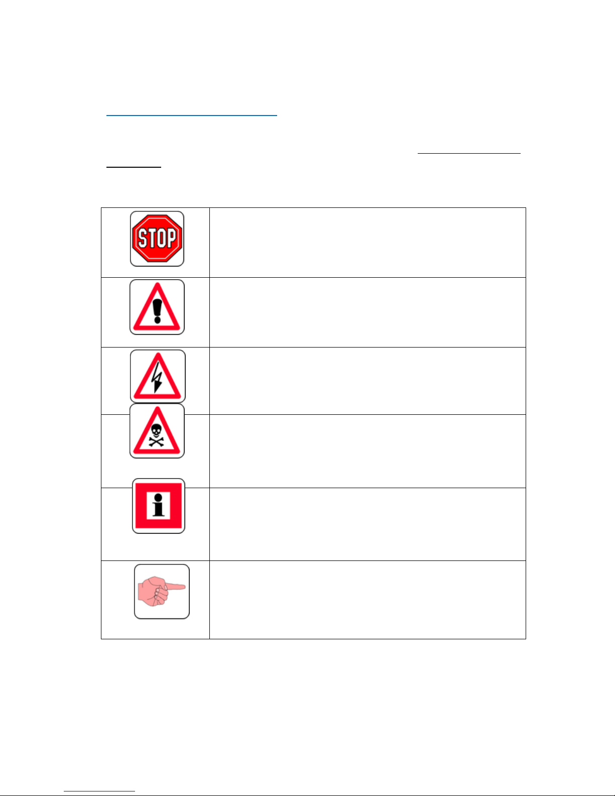
The following pictograms are used throughout this installation, operating and
maintenance manual. Their purpose is to draw your attention to particularly important
information. The type of information conveyed by the pictograms is described adjacent to
each of them.
ATTENTION:
Prohibited actions or procedures.
WARNING or INSTRUCTION:
Warning of danger. General warning that special attention should
be paid.
Important instruction that must be followed.
WARNING:
Voltage or high voltage: Risk of electrocution. Safety regulations
and accident prevention measures must be strictly adhered to.
WARNING:
Dangerous situation. Serious injury or death may result. The
product or its surroundings can be permanently damaged.
INFORMATION:
Information that must be understood or instructions that must be
followed.
IMPORTANT:
Recommended actions or measures.
Page 6

Zenith Range Instruction
Manual
Page v
Page 7

Zenith Range Instruction
Manual
Page 1
1. GENERAL
Page 8
Zenith Range Instruction
Manual
Page 2
Heater construction
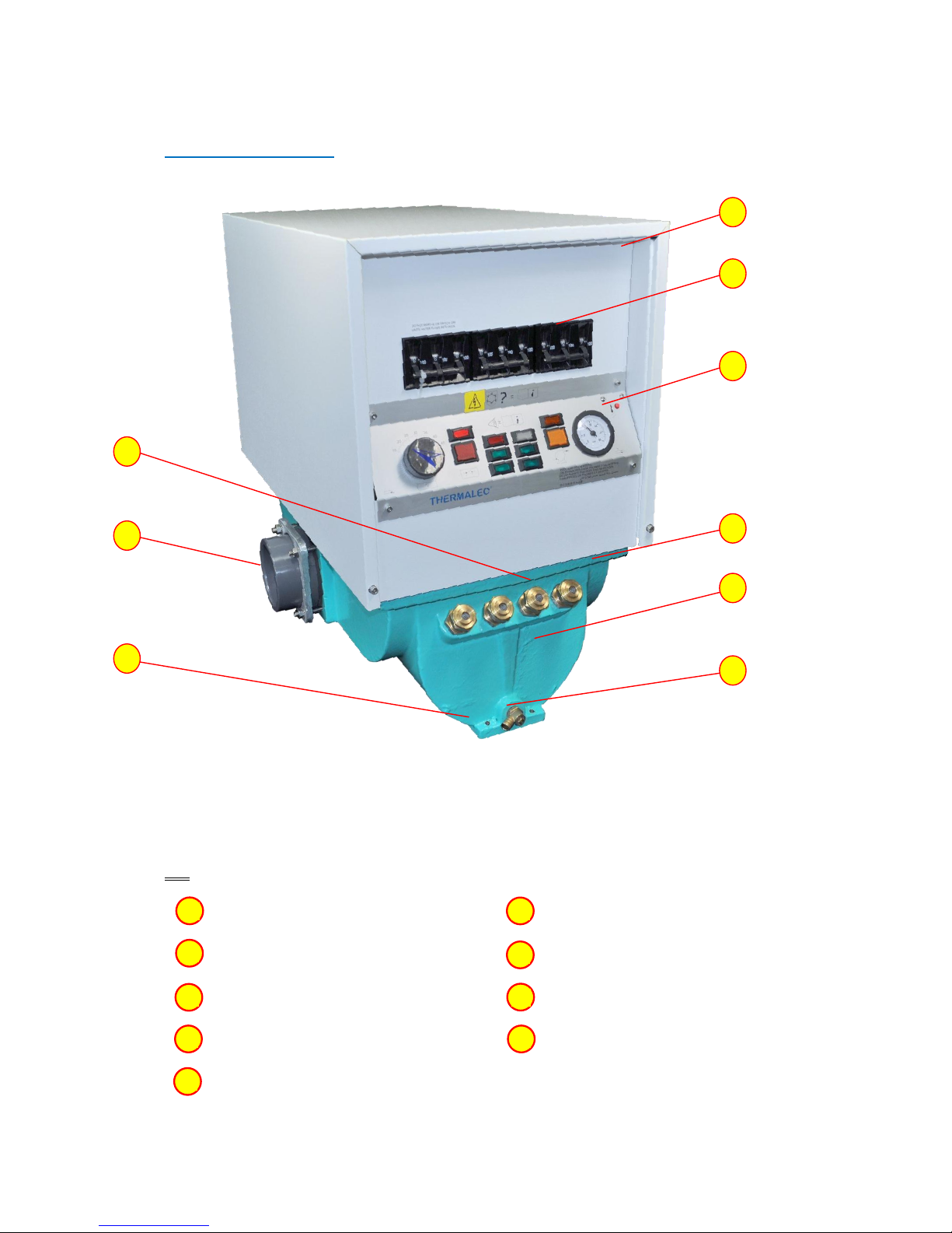
Figure 1 External features of the Thermalec® Zenith Pool Heater
KEY
Electrical control gear enclosure
Drain valve
Circuit breakers on front fascia
Support foot
Control panel on front fascia
Water inlet (default)
Water outlet (default)
Pressure relief safety valves
Heater vessel
1
2 3 4
5
6
7
8
9
Page 9
Zenith Range Instruction
Manual
Page 3
Heater construction (cont’d...)
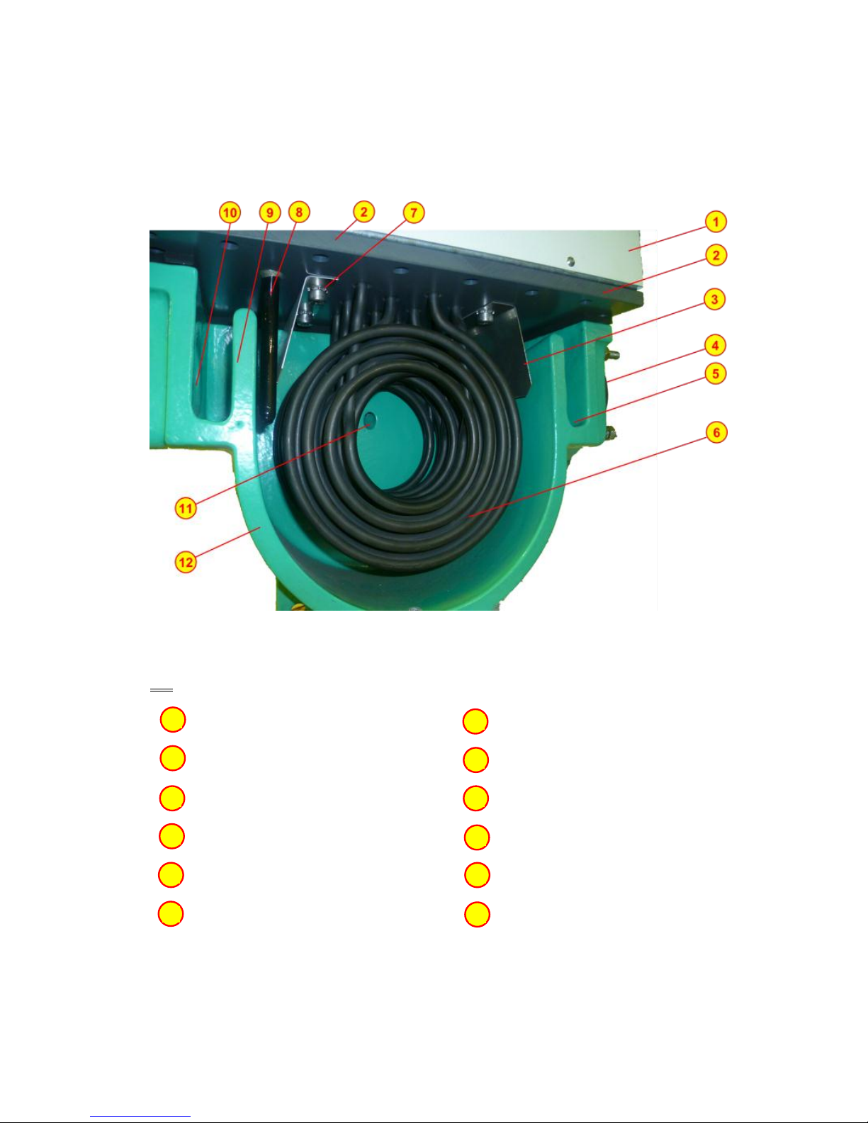
Figure 2 Sectional model of a typical Thermalec® Pool Heater
KEY
Electrical control gear enclosure
Inlet baffle plate
uPVC element holding plate
Temperature pocket
Outlet baffle plate
Water inlet overflow weir
Water outlet nozzle (default)
Water inlet port (default)
Water outlet overflow weir
Pressure relief valve port
Electrical heating elements
Heater vessel wall
1 2 3
4
5
6
7
8 9 10
11
12
Page 10

Zenith Range Instruction
Manual
Page 4
Heater construction (cont’d...)
Thermalec® electric heaters are specifically designed for use with swimming pools and
spas. The base of the heater is a fusion epoxy coated cast iron vessel through which the
water from the swimming pool flows. The vessel is fitted with four safety pressure relief
valves, a drain valve and the water inlet and outlet nozzles and its base is designed to
support the heater on a flat, solid surface.
Overflow weirs are cast into the inside of the heater vessel at the inlet and outlet nozzles.
These ensure that the vessel is kept filled with water to a constant level at all times. A
baffle plate is suspended inside the heater across its width, downstream of the inlet weir.
A similar baffle plate is suspended upstream of the outlet weir. The top edges of each of
the cast weirs are slightly sloped. This patented combination of weirs and baffles is
designed to impart a spiral regime to the flow of water through the heater. It also
prevents the direct impingement of cold water directly on to the heating elements.
The inlet and outlet pipework are connected to the heater by uPVC solvent weld socket
stub flanges. These are attached to the inlet and outlet ports on the cast iron vessel by a
steel backing flange, ensuring that the uPVC socket can be replaced if ever that were
necessary.
The outer sheath metal of the spiral circular heating elements is in highly corrosion
resistant Incoloy 825. The heating elements are suspended inside the vessel from the
thick uPVC element holding plate that covers the top of the vessel and from which the
removable baffles are also suspended. The heating elements are fitted with their
smallest profiles facing the direction of flow. The terminal ends of each element pass
through glands in the element holding plate and into the heater control enclosure that is
fixed to the top of it. Two temperature pockets protrude into the vessel through the
element holding plate, one at the inlet end and the other at the outlet end. These contain
the probes of the control and safety over-temperature liquid-filled capillary type
thermostats, respectively. An additional pocket accommodates the probe for the pool
water temperature thermometer. The joint between the uPVC element holding plate and
the top flange of the cast iron vessel is made tight by a temperature resistant silicone
rubber gasket.
The powder coated steel heater control enclosure houses the electrical switchgear, the
power connection terminals and control components.
Mains circuit breakers are provided. They will interrupt the mains power supply should
any problems occur during the normal running of the heater. Power is supplied to the
elements through heavy duty contactors. An interlock relay is provided to ensure that no
mains power can be supplied to the heating elements if the interlock signal from the
main pool filter pump is absent.
The heating elements on Zenith models are organised in 3/4 banks. A time delay relay
engages the contactors in two separate stages to reduce electrical surge and avoid a
voltage drop when the heater switches on.
Page 11

Zenith Range Instruction
Manual
Page 5
Heater construction (cont’d...)
The heaters are also equipped with a two stage temperature controller that overrides the
time delay in the event of a rapid temperature rise.
The supply of power to the heating elements is also conditioned by the two-stage control
thermostat and the over-temperature safety thermostat, which must both be set for
power to be supplied to the elements. The over-temperature thermostat is provided with
a circuit breaker shunt trip that is activated on attainment of the factory set temperature.
This trip must be manually reset to permit power to be supplied to the elements.
A fuse protects the heater power circuits, and a second fuse protects the heater status
indicator lamps.
The front face of the enclosure forms the heater control panel and accommodates the
mains circuit breakers, the pool temperature setting dial, heater status indicator lamps,
the over-temperature thermostat manual reset button, and the indicator dial of the
heater outlet water temperature thermometer.
Heater operation
Before switching any power on, it is ensured that the heater is full of water and that
water is flowing through it. The mains power is then switched on, followed by the circuit
breakers on the heater. A red indicator shows that the heater is powered. An amber light
on the heater indicates that the filter pump is in operation. If the pump does not operate
or if the pump interlock has not been fitted, the heater will not heat.
The desired pool temperature is now set using the thermostat dial. Two green lights on
the heater light in sequence, with a short time delay in between, indicating that the three
heating element banks are powered and water is being heated. When the set
temperature is reached, the green lights are extinguished. A white light on the heater
indicates that the water temperature is below the factory set safety thermostat trip level.
If this temperature is reached, the heater has overheated. In this case, the safety
thermostat trips and the unit is shut down. This trip must be reset manually.
In normal operation, the green lights will only be lit (and heating will occur) if all the other
lamps are lit and the pool water temperature is below the set temperature.
Heater technical details
Standards
Thermalec® pool and Spa heaters are CE marked and comply with:
EU Council Directive 89/336/EEC & 93/068/EEC on Electromagnetic compatibility
EU Council Machinery Directive 98/37/EEC
EU Council Low Voltage Directive 2006/95/EEC & 72/23EEC
Harmonised Standards: EN55014, EN55104, EN5501, EN5502, CEI801-2, CEI801-3 and
EN60335-2-35
Page 12

Zenith Range Instruction
Manual
Page 6
Materials of construction
Heater vessel: Fusion epoxy coated cast iron
Element holding plate: uPVC
Gasket: Silicone rubber
Water connections: uPVC socket (metric or imperial)
Heater elements: Incoloy 825 sheath
Electrical enclosure: Powder coated steel or leather grain coated steel
Operating data
Water inlet/outlet: Socket for 63 mm or 3” NB pipe
Max. water temperature: 52°C heater outlet
Operating pressure: 2.0 bar max.
Ambient temperature: 40°C max.
Pool temperature control range: 15°C to 45°C
Thermostat operating differential: 0.5 C°
Heater technical details (cont’d...)
Permissible water flowrate ranges
Zenith Heater Installed power
96 kW
120 kW
144 kW
168 kW
Maximum (hard water) l/min.
700
700
700
700
Maximum (soft water) l/min.
350
350
350
350
Minimum l/min.
160
200
240
280
Control and indication
Power supply isolation: 2 x 3 pole 100A heavy duty circuit breakers (96 & 120 kW
heaters) and 3 x 3 pole 100A heavy duty circuit breakers
(144 & 168kW heaters) on front fascia.
Water temperature cut-out: Factory set to trip at water outlet temperature of 52 °C.
Manual reset on front fascia.
Thermostats: Pressurised liquid filled capillary type.
Pool temperature indicator: Pressurised liquid filled capillary thermometer with
analogue indicator dial.
Pool temperature control: Analogue dial - calibrated 15°C to 45°C and graduated at
1 C° intervals.
Mains indicator lamps: Red (mains power on), Amber (filter pump running)
Page 13

Zenith Range Instruction
Manual
Page 7
Control and indication(cont’d…)
Status indicator lamps: Red (heater circuit breaker armed and powered), White
(safety thermostat trip armed), Amber (pump interlock
relay OK), 4 x Green (heating elements powered). X 1
Red EHOT.
Electrical data
Protection level: IP 21 Fuses: 2 x 2 Amp
Pump interlock voltage: 230 V AC Element heat flux: 11.5 W/cm2 max.
Standard Power Supply: 400V/3ph/50Hz
Model Ref.
Load kW
Current Amps
Per phase
Elements
(no. x nominal kW)
ZHR 96
96 kW
140
12 x 8 kW
ZHR120
120 kW
174
15 x 8 kW
ZHR144
144 kW
206
18 x 8 kW
ZHR168
168 kW
244
21 x 8 kW
Weights and dimensions
Packed dimensions: 81 x 58 x 83 cm
Packed weight: 145 kg
Page 14

Zenith Range Instruction
Manual
Page 8
2. INSTALLATION
Page 15

Zenith Range Instruction
Manual
Page 9
Introduction
The Thermalec Zenith heater is designed for use with swimming pools, spas and other
similar installations.
To prevent damage to the heater it must not be operated unless it is fully flooded with a
sufficient flow of pool water.
An interlock is fitted, ensuring that the heater cannot be operated unless the filter pump
is running.
A temperature controller is fitted to allow control of the water temperature in the range
15 to 45°C. The maximum water temperature is limited to 52°C by a safety thermostat.
A thermometer displays the heater outlet water temperature when the heater is OFF.
When the heater is ON the reading may be slightly higher, depending on the flow rate
through the heater.
The heater is designed to operate at a maximum pressure of 2 bar (30 psi). Exceeding this
limit will operate the pressure relief valves located on the heater vessel.
The pool temperature will rise gradually if the heater has been sized according to our
published sizing methods.
These are designed such that in May of an average year, in North-western Europe, an
outdoor pool that is heated during the off-peak power supply period of seven hours a
day, will take about five nights to reach the required temperature. It is assumed that the
pool would be equipped with a solar cover. The actual time taken to reach temperature is
determined by the ambient air and water temperatures and by the overall heat losses
from the pool.
Installation
Regulations & Codes of Practice.
This heater must be installed
by a competent and certified
person, strictly
in accordance
with
the relevant standards and regulations in
the country of use
for the installation of
mains powered electrical equipment in the vicinity swimming
.
In the UK these standards are BS 7671 (lEE Regulations,
16th
Edition) and the
SPATA
standards. Electrical installations for swimming pools in
the UK are classified as
‘Notifiable’
under Part P of the Building Regulations 2005. This means
that a
qualified
electrician, registered
with a self-certification
scheme, must carry out the work.
Alternatively,
another
person
may carry out the work,
but it must be notified
to the local
authority who will arrange for inspection
& testing to be carried out.
Page 16
Zenith Range Instruction
Manual
Page 10
Location
The protection rating of the heater is lP21 and it should be installed in a weatherproof
enclosure with good drainage. A suitable anti-condensation heater should be provided in
high ambient humidity conditions, since moisture can damage electrical components.
The heater must be installed in a cool, dry location. Regulations that stipulate minimum
distances for electrical equipment from water sources must be observed.
Positioning the heater on the flowsheet
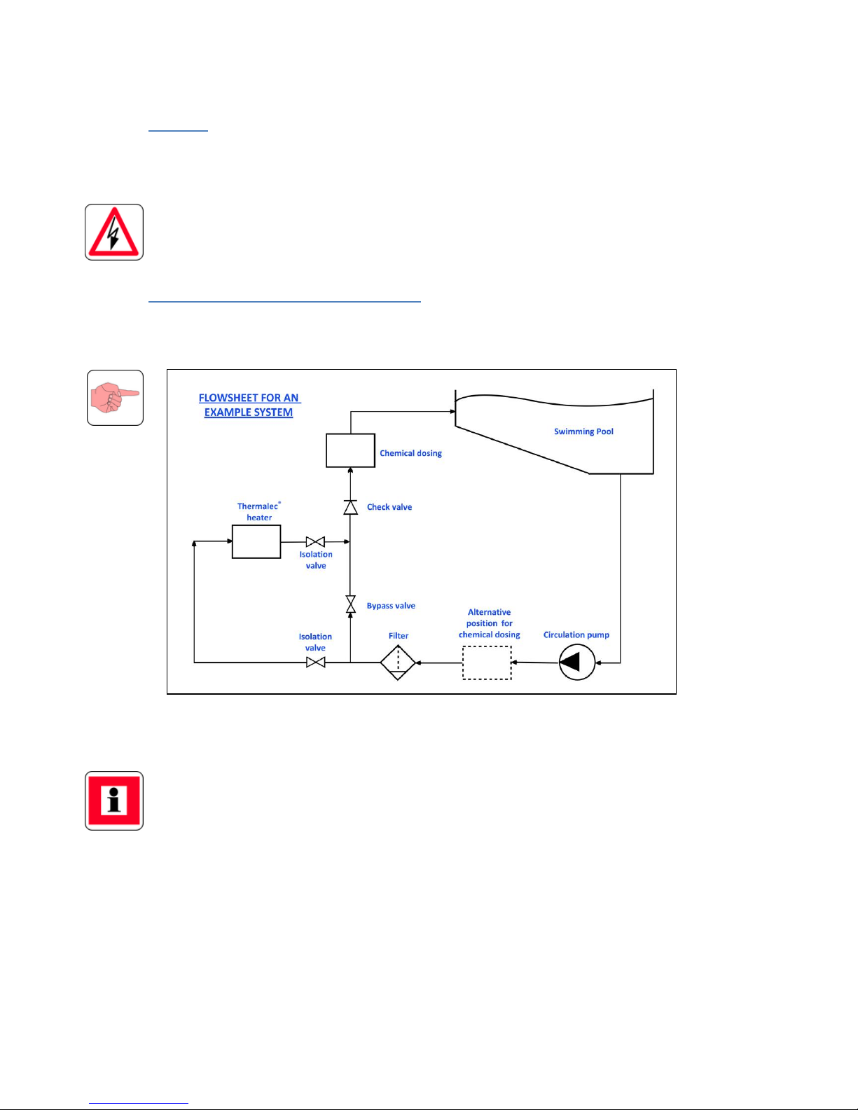
The following diagram illustrates a suggested plant flowsheet showing the positioning of
the heater with respect to the other plant room process units.
Chemical dosing systems should not be installed adjacent to the heater. lf installed
upstream of the heater it must be before the filter. lf installed downstream, a check
valve must be fitted to
prevent
backflow of chemicals when the filter
pump
is not
operating. There should be a drop in level between the
pipe
leaving the heater and
entering the dosing system.
The
pipe
system should have valves to isolate the heater. A shut off valve should be
included in the bypass to stop the flow around the heater when not required.
Figure 3 Suggested heater position on plant room flowsheet
Page 17
Zenith Range Instruction
Manual
Page 11
Positioning and piping connection of the heater
To enable the power supply cable to be inserted through the
back
panel,
allow space
behind the heater
equal to at least the depth
of the heater casing.
The minimum clearance above the heater should be 400mm.
The default water flow direction through the heater is left to right, allowing the
temperature controller to sense the temperature coming from the pool. This direction
can, however, be modified by following the instructions below.
The heater must never be installed at the highest point of a pipework system. Water may
drain from the heater causing damage to it. The pipework must be designed such that the
heater is always full of water.
The heater must always be installed horizontally and properly levelled; NEVER install
vertically.
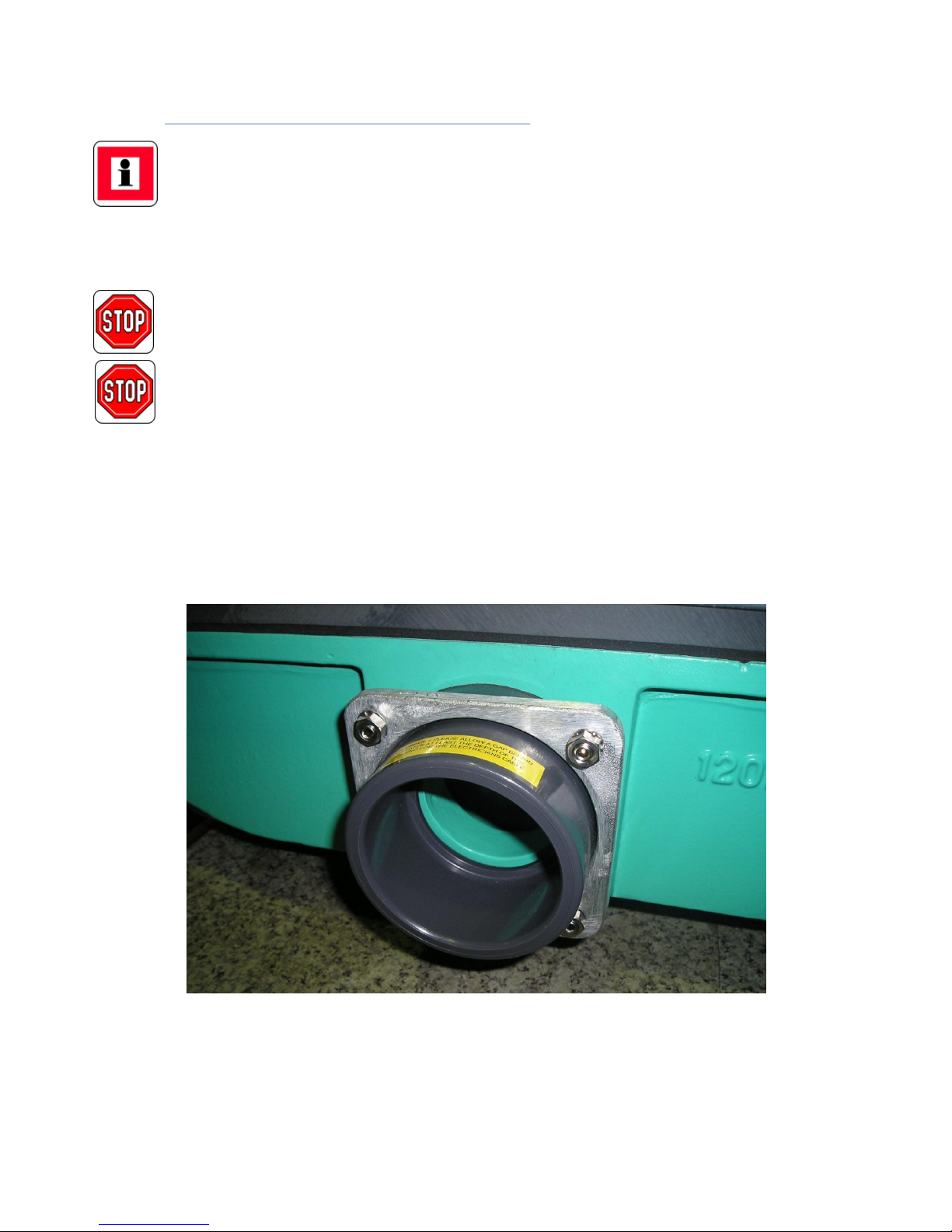
Pipe connections are stub flanges to suit 120 mm (3") nominal bore pipe (uPVC or ABS). lf
using ABS the solvent jointing compound must be suitable for both materials. Reducers
may be fitted to suit smaller pipes.
It is not necessary to fit unions either side of the heater as the stub flanges are easily
disconnected from the heater, by removing the nuts securing the aluminium backing
flanges to the heater. In very tight installations, the studs themselves may be unscrewed.
Figure 3 Water connection on a Thermalec® pool heater
Page 18

Zenith Range Instruction
Manual
Page 12
Positioning and piping connection of the heater(cont’d…)
If required levelling screws can be used in the four holes in the base of the heater. These
are used to level the heater. More importantly, they will stop the heater rocking on its
base. If the heater is installed on a shelf, the holes may be used to screw the heater
down. This can be achieved by bolting the heater down, or by using wood screws from
the top.
If the heater is connected to rigid pipework and is floor mounted, the levelling screws,
together with the pipes and cable will usually keep the heater stable.
Direction of flow through the heater
The default direction of flow of pool water through the heater is left to right. This allows
the temperature controller to sense the temperature of the water coming from the pool.
If required, the flow direction may be reversed by exchanging the positions of the probes
of the control thermostat and the safety thermostat. This is carried out as follows:
a) Switch heater circuit breakers to OFF;
b) Switch main power supply and pump interlock supply to OFF;
c) Remove main cover;
d) Reverse the two probes. The controller probe is situated at the left-hand end of
the element plate. The safety thermostat probe is situated at the right-hand end
of the element plate and is marked with a short length of white sheathing;
e) Move the thermometer probe to the empty pocket on the left-hand side;
f) Replace and fix the top cover before reconnecting connecting electrical supplies.
Electrical Installation
All electrical work must be carried out by a competent and experienced electrician,
certified according to the regulations in the country of installation.
Earth leakage protection must be provided by fitting a Residual Current Device (RCD) to
installations involving swimming pools or spas. The RCD must be rated to carry the
current drawn by the heater (see table below) and the current drawn by other items of
equipment on the same supply.
Overcurrent protection must also be provided in the form of a Circuit Breaker. Due to the
continuous high load that will be drawn, the circuit breaker should be rated at least 20%
higher than of the current shown in the following table.
Page 19
Zenith Range Instruction
Manual
Page 13
Electrical installation (cont’d...)
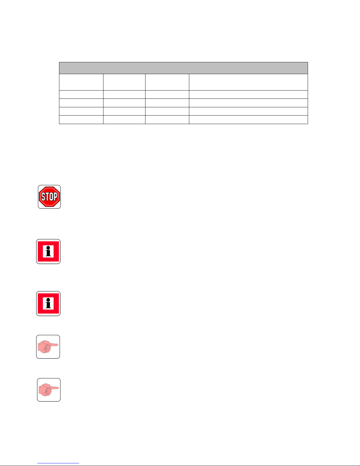
Standard Power Supply: 400V/3ph/50Hz
Model Ref.
Load kW
Current Amps
Per phase
Elements
(no. x nominal kW)
ZHR 96
68 kW
140
12 x 8 kW
ZHR120
120 kW
174
15 x 8 kW
ZHR144
144 kW
206
18 x 8 kW
ZHR168
168 kW
244
21 x 8 kW
The size and specification of the cable to the heater should be decided by consulting the
electrical regulations applicable in the country of installation.
To minimise the effects of voltage drop, the plant room should be located as close as
possible to the main electrical supply.
The supply cable enters the heater via the removable plate at the back of the heater. The
plate should be drilled out to suit the size of cable gland used.
Under no circumstances should cable be installed through the metal plate without the
use of a gland.
To access the terminals, remove the heater cover and terminal cover. The wires of the
incoming power supply (L1, L2, L3, N and E) must be connected to the appropriate
terminals.
It is vital that all wires are firmly terminated into each terminal. A 6mm spanner should
be used to ensure that the clamps are pulled firmly down onto the incoming cable ends.
Make sure that the cable is of sufficient diameter to ensure a good clamp is made and if
required, wind a length of copper strand around the other strands to increase the
diameter. After termination, check all the cables for tightness and replace both sets of
covers.
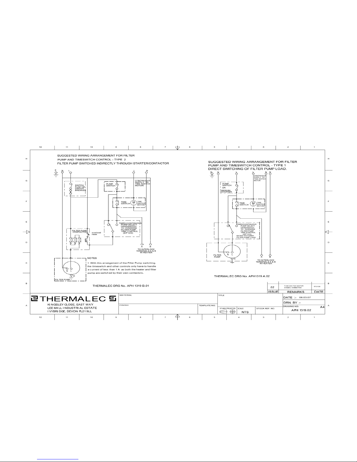
The heater will not operate without a pump interlock supply that switches 230V ON when
the filter pump is running. The live of this supply should be connected to terminal A and
the neutral to terminal B of the heater. The supply must be taken from the last device
switching the filter pump, to ensure that the heater will switch off at the same time as
the filter pump.
This pump interlock supply can also be used to control the operation of the heater
further. A time switch can (for example) be fitted to interrupt the supply to terminal A,
ensuring that it can only come on during specific periods of cheap electricity. This is
detailed on drawing APH 1319, together with arrangements for an override switch
allowing the filter pump to be run continuously.
Thermalec also produce a range of Pool Control Panels, which enable pumps, heating and
all other pool items to be controlled from a single control box. All panels are made to
order, to match the specific equipment. Please contact the Sales office for more details.
Page 20
Zenith Range Instruction
Manual
Page 14
Figure 4 Drg. APH 13 19 Heater filter pump interlock
Page 21

Zenith Range Instruction
Manual
Page 15
3. OPERATION
Page 22

Zenith Range Instruction
Manual
Page 16
Commissioning
First Start-up
When using the heater for
the first time
(or
after it has been
isolated
for the winter)
it is vital that the heater is commissioned using the correct
procedure.
Failure to do
so will result in serious damage to the heater.
a) Check
heater
circuit breakers are all OFF.
b) Check main
power
supply is OFF.
c) Check filter
pump
is OFF.
d) Check heater drain valve is closed.
e) Set
pool
temperature controller to less than 15'C
f) Check heater isolation valves are OPEN and water
is flowing
through the heater
g) Check that the heater is full of water before
proceeding
h)
Check
that time switch
(if
fitted) is on and heater control supply is
enabled.
i) Switch on the Filter Pump - Check
positive
flow of water into pool:
Amber
pump
supply lamp ⑨ON
j) Switch main
power
supply
to ON. Red mains power supply light ③ is ON.
k) Remove seal from heater circuit breakers and switch ON
Red ⑥, ⑦ and Amber ⑧heater status lamps ON
l) Set
pool
temperature controller to desired temperature
First Green heater status lamp ④ ON
(closing
of contactor can be heard);
After a delay of several minutes the second bank of contactors will close.
Second Green heater status lamp ⑤ ON
(closing
of contactor can be heard).
After a delay of several minutes the third bank of contactors will close.
Third Green heater status lamp ⑤ ON (closing of contactor can be heard);
After a delay of several minutes the forth bank of contactors will close.
Fourth Green heater status lamp ⑤ ON
(closing
of contactor can be heard).
All lamps are now ON
m) Turn filter
pump
OFF.
Amber
pump
supply lamp ⑨ switches OFF. Green ④, ⑤ and Amber ⑧
heater status lamps switch OFF
n) Turn filter
pump
ON
o) Reset the time switch.
Page 23
Zenith Range Instruction
Manual
Page 17
Water flowrate through the heater
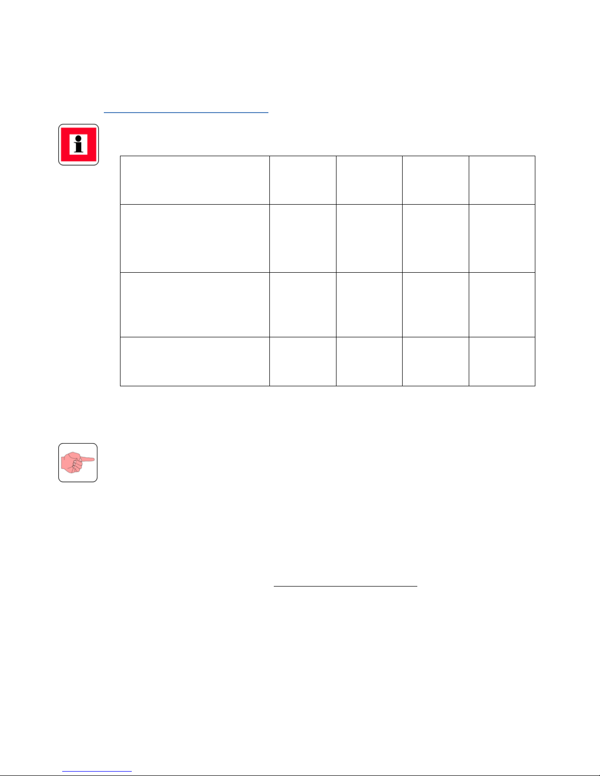
The flow rate of water through the heater should be set within the ranges given in the
following table:
Flow Rate
96 kW
120 kW
144 kW
168 kW
Hard water maximum
- use bypass above this rate
- minimise scale formation
9000 gal/hr
700 l/min
9000 gal/hr
700 l/min
9000 gal/hr
700 l/min
9000 gal/hr
700 l/min
Soft water maximum
- use bypass above this rate
- improves element life
4500 gal/hr
350 l/min
4500 gal/hr
350 l/min
4500 gal/hr
350 l/min
4500 gal/hr
350 l/min
Minimum
1920 gal/hr
160 l/min
2400 gal/hr
200 l/min
2880 gal/hr
240 l/min
3360 gal/hr
280 l/min
Calculation of the water flowrate
To calculate the exact flowrate of water flowing through the heater, apply the following
method:
Allow the pump to run with the heater off for a few minutes;
Take a reading on the outlet water temperature indicator;
Then switch the heater on and allow about five minutes for the temperature to
stabilise before taking a second temperature reading.
The difference between the two readings gives the exact temperature rise for that
particular flow rate;
Use the following formula to establish the rate:
Flowrate
(litres/min.)
=
Heater kW rating x 14.4
Temperature rise in C°
Page 24

Zenith Range Instruction
Manual
Page 18
Decommissioning
Winterisation
If the pool is to be closed over the winter, damage may be caused by chemically treated
water and debris left standing in the heater vessel. The following procedure should be
followed to preserve the integrity of the heater:
a) Switch heater circuit breakers to OFF;
b) Switch main power supply and pump interlock supply to OFF;
c) Remove main cover and check main terminals for tightness;
d) Apply WD40 (or similar to) all electrical components, particularly the
contactors;
e) Close heater isolation valves;
f) Empty vessel using drain valve;
g) Remove drain valve locking screw and check for debris at the bottom of vessel
with 6mm dowel rod.
If the rod cannot be fully inserted then consideration should be given to
opening the vessel to remove debris.
If the pool is to be kept in a semi-operational condition during the winter then the heater
may only be left full of water if the filter pump is fitted with a frost-stat.
Operation with salt or sea water
If the heater is to be used on sea water pools or salt water pools, it is recommended that
the heater vessel be flushed through with fresh water at frequent intervals
(approximately after every 3 weeks of use).
This is particularly important when the heater is used with very high salinity sea water or
in salt spas.
Fault finding
Safety Warning: The electrical supplies to the heater are potentially lethal. All
maintenance and repair operations should be carried out by trained personnel,
supported by appropriate safe systems of work. Before removing the top cover ensure
that, both the three phase main supply and, the single phase pump interlock supply, are
both isolated.
Page 25

Zenith Range Instruction
Manual
Page 19
Diagnostics
Status Lamps
The lamps will light in sequence in steps 1 to 7. The green lamps will only light (and the
pool water be heated) when the other lamps are all lit. The following actions should be
taken if any of these lamps are not lit:
Controller Drift
If, over time, the calibration of the temperature controller drifts such that the value set
on the dial has to be gradually increased to maintain the same actual pool water
temperature, then the thermostat should be replaced.
Contactors frequently switching
Switching of the contactors every few minutes indicates that the direction of water flow
is incorrect.
Heater circuit breaker trips
Check if red reset button from Safety Thermostat has popped out. lf so reset
and wait, if
thermostat trips again check for sufficient water flow and air in system. lf trip is not
associated with this check individual heating
elements for insulation resistance.
Protective
Devices on Supply Trip
If RCD has tripped, first check that other equipment in the installation has not caused the
trip, then check heating elements for insulation resistance. lf MCB has tripped, check
that it is correctly rated
.
Noise
Excessive
"buzzing"
when heating indicates t h a t the re ar e small amounts of rust on
the pole faces of the contactor. WD40 should be applied to the affected area.
Pool not reaching desired temperature
lf the status lamps are lit as described above and the contactors can be heard engaging,
then the heater can be assumed to be operating correctly.
lf the pool does not reach the required temperature after an appropriate number of
hours then the current drawn by the heater should be checked using a clip-on ammeter.
Page 26

Zenith Range Instruction
Manual
Page 20
Diagnostics (cont’d…)
An alternative method is to set the temperature control several degrees above normal
and use the main supply meter to check how many Units (kWh) the heater consumes in
an hour. This figure should be slightly above the kW rating of the heater, allowing for the
filter pump and other domestic equipment on the same supply.
If the power consumption is less than the rating of the heater then the issue is elsewhere
in the system, for example:
Low voltage
supplied to the heater, indicating that cable diameter is too small or
run is too long;
Inadequate
mixing of the warm water from the heater with the cooler water in
the
pool,
leading to a layer of
warmer
water forming at the height of the inlets.
To cure this, aim the direction of the
pool
inlet
jet
downwards;
Incorrect
setting of any time witches fitted to heater or filter
pump;
The time switches are not synchronised with the main off=peak electrical supply
meter;
Lack of water flow caused by insufficient
pump
head, or blockages in the
pipework.
Warranty
The heater is guaranteed for two years against faulty workmanship or materials. This
does not cover damage caused by incorrect commissioning & maintenance or by other
neglect of the heater. In the event of a claim, Thermalec will at it sole discretion replace
the heater, provide replacement parts or effect a repair at its factory or its local
distributor.
 Loading...