

Page 1

®
8
480V
ULTRA-CUT 400 XT
PLASMA CUTTING SYSTEM
™
Operating
Manual
Revision: AH Issue Date: May 27, 2015 Manual No.: 0-5275
Thermal-Dynamics.com
Page 2

®
WE APPRECIATE YOUR BUSINESS!
Congratulations on your new Thermal Dynamics product. We are proud to have you as our customer
and will strive to provide you with the best service and reliability in the industry. This product is backed
by our extensive warranty and world-wide service network. To locate your nearest distributor or service
agency call 1-800-752-7622, or visit us on the web at www.thermal-dynamics.com.
This Operating Manual has been designed to instruct you on the correct use and operation of your
Thermal Dynamics product. Your satisfaction with this product and its safe operation is our ultimate
concern. Therefore please take the time to read the entire manual, especially the Safety Precautions.
They will help you to avoid potential hazards that may exist when working with this product.
YOU ARE IN GOOD COMPANY!
The Brand of Choice for Contractors and Fabricators Worldwide.
Thermal Dynamics is a Global Brand of manual and automation Plasma Cutting Products.
We distinguish ourselves from our competition through market-leading, dependable products that
have stood the test of time. We pride ourselves on technical innovation, competitive prices, excellent delivery, superior customer service and technical support, together with excellence in sales and
marketing expertise.
Above all, we are committed to developing technologically advanced products to achieve a safer
working environment within the welding industry
Page 3

!
WARNING
Read and understand this entire Manual and your employer’s safety practices
before installing, operating, or servicing the equipment.
While the information contained in this Manual represents the Manufacturer’s
best judgement, the Manufacturer assumes no liability for its use.
Plasma Cutting Power Supply, Ultra-Cut 400 XT
Operating Manual No. 0-5275
Published by:
Thermal Dynamics Corporation.
2800 Airport Rd.
Denton, Texas 76207
www.thermal-dynamics.com
© Copyright 2013, 2014, 2015 by
Thermal Dynamics Corporation.
All rights reserved.
Reproduction of this work, in whole or in part, without written permission of the
publisher is prohibited.
The publisher does not assume and hereby disclaims any liability to any party for any
loss or damage caused by any error or omission in this Manual, whether such error
results from negligence, accident, or any other cause.
™
Original Publication Date: April 22, 2013
Revision Date: May 27, 2015
Record the following information for Warranty purposes:
Where Purchased: ___________________________________
Purchase Date:______________________________________
Power Supply Serial #:_______________________________
Torch Serial #:_______________________________________
Page 4

Be sure this information reaches the operator.
You can get extra copies through your supplier.
CAUTION
These INSTRUCTIONS are for experienced operators. If you are not fully familiar with
the principles of operation and safe practices for arc welding and cutting equipment,
we urge you to read our booklet, “Precautions and Safe Practices for Arc Welding,
Cutting, and Gouging,” Booklet 0-5407. Do NOT permit untrained persons to install,
operate, or maintain this equipment. Do NOT attempt to install or operate this equipment until you have read and fully understand these instructions. If you do not fully
understand these instructions, contact your supplier for further information. Be sure
to read the Safety Precautions before installing or operating this equipment.
USER RESPONSIBILITY
This equipment will perform in conformity with the description thereof contained in this manual and accompanying
labels and/or inserts when installed, operated, maintained and repaired in accordance with the instructions provided. This
equipment must be checked periodically. Malfunctioning or poorly maintained equipment should not be used. Parts that
are broken, missing, worn, distorted or contaminated should be replaced immediately. Should such repair or replacement
become necessary, the manufacturer recommends that a telephone or written request for service advice be made to the
Authorized Distributor from whom it was purchased.
This equipment or any of its parts should not be altered without the prior written approval of the manufacturer. The
user of this equipment shall have the sole responsibility for any malfunction which results from improper use, faulty maintenance, damage, improper repair or alteration by anyone other than the manufacturer or a service facility designated by
the manufacturer.
READ AND UNDERSTAND THE INSTRUCTION MANUAL BEFORE INSTALLING OR
PROTECT YOURSELF AN D OTHERS!
!
OPERATING.
Page 5

ASSUREZ-VOUS QUE CETTE INFORMATION EST DISTRIBUÉE À L’OPÉRATEUR.
ATTENTION
VOUS POUVEZ OBTENIR DES COPIES SUPPLÉMENTAIRES CHEZ VOTRE FOURNISSEUR.
Les INSTRUCTIONS suivantes sont destinées aux opérateurs qualiés seulement.
Si vous n’avez pas une connaissance approfondie des principes de fonctionnement
et des règles de sécurité pour le soudage à l’arc et l’équipement de coupage, nous
vous suggérons de lire notre brochure « Precautions and Safe Practices for Arc Welding, Cutting and Gouging, » Brochure 0-5407. Ne permettez PAS aux personnes non
qualiées d’installer, d’opérer ou de faire l’entretien de cet équipement. Ne tentez
PAS d’installer ou d’opérer cet équipement avant de lire et de bien comprendre ces
instructions. Si vous ne comprenez pas bien les instructions, communiquez avec
votre fournisseur pour plus de renseignements. Assurez-vous de lire les Règles de
Sécurité avant d’installer ou d’opérer cet équipement.
RESPONSABILITÉS DE L’UTILISATEUR
Cet équipement opérera conformément à la description contenue dans ce manuel, les étiquettes d’accompagnement
et/ou les feuillets d’information si l’équipement est installé, opéré, entretenu et réparé selon les instructions fournies. Vous
devez faire une vérication périodique de l’équipement. Ne jamais utiliser un équipement qui ne fonctionne pas bien ou n’est
pas bien entretenu. Les pièces qui sont brisées, usées, déformées ou contaminées doivent être remplacées immédiatement.
Dans le cas où une réparation ou un remplacement est nécessaire, il est recommandé par le fabricant de faire une demande
de conseil de service écrite ou par téléphone chez le Distributeur Autorisé de votre équipement.
Cet équipement ou ses pièces ne doivent pas être modiés sans permission préalable écrite par le fabricant. L’utilisa-
teur de l’équipement sera le seul responsable de toute défaillance résultant d’une utilisation incorrecte, un entretien fautif, des
dommages, une réparation incorrecte ou une modication par une personne autre que le fabricant ou un centre de service
désigné par le fabricant.
ASSUREZ-VOUS DE LIRE ET DE COMPRENDRE LE MANUEL D’UTILISATION AVANT
!
D’INSTALLER OU D’OPÉRER L’UNITÉ.
PROTÉGEZ-VOUS ET LES AUTRES!
Page 6

This Page Intentionally Blank
Page 7

TABLE OF CONTENTS
SECTION 1: SAFETY ........................................................................................ 1-1
1.01 Safety Precautions - ENGLISH ........................................................................ 1-1
1.02 Précautions de sécurité - FRENCH CANADIAN ............................................... 1-6
SECTION 2: SPECIFICATIONS ............................................................................. 2-1
2.01 General Description Of The System ................................................................ 2-1
2.02 Plasma Power Supply ..................................................................................... 2-1
2.03 Remote Arc Starter ......................................................................................... 2-1
2.04 Gas Control Module ........................................................................................ 2-1
2.05 Precision Plasma Cutting Torch ...................................................................... 2-1
2.06 Specifications & Electrical Requirements ....................................................... 2-1
2.07 Power Supply Dimensions .............................................................................. 2-2
2.08 Power Supply Rear Panel Features ................................................................. 2-3
2.09 Gas Requirements .......................................................................................... 2-4
2.10 Gas Applications ............................................................................................. 2-4
2.11 XT Torch Specifications ................................................................................. 2-5
SECTION 3: INSTALLATION ............................................................................... 3-1
3.01 Installation Requirements ............................................................................... 3-1
3.02 System Layout ............................................................................................... 3-2
3.03 Recommended Gas Supply Hose .................................................................... 3-3
3.04 Leads and Cables All Amperage ...................................................................... 3-3
3.05 Lift the Power Supply ..................................................................................... 3-4
3.06 Connect Input Power and Ground Cables ....................................................... 3-5
3.07 Connect Work Cable and Pilot and Negative Leads ......................................... 3-6
3.08 Ground Connections ....................................................................................... 3-7
3.09 Connect Coolant Leads ................................................................................. 3-10
3.10 Connect Cables for CNC, Remote Arc Starter, GCM and HE 400 ................... 3-11
3.11 Handling and Installation of Fiber Optics ...................................................... 3-12
3.12 Set Switches on the Command - Control Module ......................................... 3-15
3.13 Height Control Connections .......................................................................... 3-17
3.14 Gas Control Module Installation .................................................................... 3-18
3.15 Fiber Optic Cable Installation ........................................................................ 3-20
3.16 Gas Control Module: Control, Input, and Output Connections ...................... 3-22
3.17 HE400XT COOLER ........................................................................................ 3-23
3.18 Install Remote Arc Starter ............................................................................. 3-25
3.19 Torch Valve Installation ................................................................................. 3-32
3.20 Connecting Torch .......................................................................................... 3-34
3.21 Install Consumable Torch Parts .................................................................... 3-35
3.22 Voltage Divider for iHC Torch Height Control ................................................ 3-38
3.23 Complete the Installation .............................................................................. 3-40
Page 8

TABLE OF CONTENTS
SECTION 4: OPERATION ................................................................................... 4-1
4.01 Power Supply Control Panel ........................................................................... 4-1
4.02 System Operation ........................................................................................... 4-2
4.03 Gas Selection .................................................................................................. 4-4
4.04 GCM 2010 Gas Control Module Operation ...................................................... 4-6
4.05 GCM 2010 First Time Operation Matching Gas Control to Lead Length ........ 4-10
4.06 GCM 2010 Sequence Of Operation ............................................................... 4-10
4.07 Power Supply Status Codes .......................................................................... 4-13
4.08 Remote Arc Starter Trouble Shooting ........................................................... 4-21
SECTION 5: MAINTENANCE ............................................................................... 5-1
5.01 General Maintenance ...................................................................................... 5-1
5.02 External Coolant Filter Cleaning Procedure ..................................................... 5-1
5.03 Coolant Replacement Procedure ..................................................................... 5-2
SECTION 6: REPLACEMENT ASSEMBLIES & PARTS ................................................. 6-1
6.01 Replacement Power Supply ............................................................................ 6-1
6.02 System Layout ................................................................................................ 6-2
6.03 Recommended Gas Supply Hose .................................................................... 6-2
6.04 Leads And Cables All Amperages .................................................................... 6-3
6.05 Power Supply External Replacement Parts .................................................... 6-5
6.06 Power Supply Replacement Parts - Upper Right Side ..................................... 6-6
6.07 Power Supply Replacement Parts - Lower Right Side ................................... 6-7
6.08 Power Supply Replacement Parts - Rear Panel .............................................. 6-8
6.09 Power Supply Replacement Parts - Left Side .................................................. 6-9
6.10 Gas Control Module (GCM-2010) Replacement Parts ................................... 6-10
6.11 Gas Control Module (GCM-2010) Replacement Parts ................................... 6-11
6.12 Remote Arc Starter (RAS-1000 XT) Replacement Parts ............................... 6-12
6.13 HE400XT Heat Exchanger - Replacement Parts ............................................ 6-13
6.14 XTL Torch Valve Assembly External Replacement Parts ............................... 6-14
6.15 XTL Torch Valve Assembly Internal Replacement Parts ................................ 6-15
SECTION 7: TORCH MAINTENANCE ................................................................... 7-1
7.01 Consumable Removal ..................................................................................... 7-1
7.02 O-Ring Lubrication ......................................................................................... 7-2
7.03 Parts Wear ...................................................................................................... 7-3
7.04 Torch Consumables Installation ...................................................................... 7-4
7.05 Coolant Leak Trouble-Shooting ...................................................................... 7-6
APPENDIX 1: Remote Arc Starter Schematic .......................................................... A-1
APPENDIX 2: Gas Control and Torch Valve Schematic ............................................... A-2
APPENDIX 3: Gas Control Module Plumbing Diagram ............................................... A-4
APPENDIX 4: Gas Control Module PCB Layout ........................................................ A-5
APPENDIX 5: Gas Control Display Module PCB Layout .............................................. A-6
APPENDIX 6: CNC - Control Module PCB Connections ............................................... A-7
Page 9

TABLE OF CONTENTS
APPENDIX 7: CNC ......................................................................................... A-8
CNC functions ............................................................................................................... A-8
CNC Input / Output Descriptions ................................................................................. A-10
Simplified CNC Circuit .................................................................................................A-12
CNC Connections ........................................................................................................ A-14
CNC Cable Color Code ................................................................................................ A-15
APPENDIX 8: CCM CPU PCB Layout ...................................................................A-16
APPENDIX 9: CCM I/O PCB Layout .....................................................................A-18
APPENDIX 10: Pilot PCB Layout ........................................................................A-20
APPENDIX 11: Relay and Interface PCB Layout ......................................................A-22
APPENDIX 12: Display PCB Layout ....................................................................A-24
APPENDIX 13: System Bias PCB Layout ..............................................................A-26
APPENDIX 14: Main Inverter Bottom PCB Layout ....................................................A-28
APPENDIX 15: Main Inverter Top PCB Layout ........................................................ A-30
APPENDIX 16: Control and Fault PCB Layout ........................................................A-32
APPENDIX 17: Cap Bias Bottom PCB Layout .........................................................A-34
APPENDIX 18: Cap Bias Top PCB Layout .............................................................. A-35
APPENDIX 19: Suppressor PCB Layout ................................................................A-36
APPENDIX 20: COOLING DIAGRAM ....................................................................A-37
APPENDIX 21: System Schematic 400A, 480V PG 1 .................................................A-38
APPENDIX 22: System Schematic 400A, 480V PG 2 .................................................A-40
APPENDIX 23: ADVANCED TROUBLESHOOTING .....................................................A-42
APPENDIX 24: SL100 INTERCONNECTION ............................................................A-88
APPENDIX 25: HE 400 XT CONNECTION ..............................................................A-90
APPENDIX 26: SL100 Torch Option ....................................................................A-91
APPENDIX 27: PUBLICATION HISTORY ................................................................A-98
INTERNATIONAL CONTACT INFORMATION ................................................. BACK COVER
Page 10

This Page Intentionally Blank
TABLE OF CONTENTS
Page 11

ULTRA-CUT 400 XT
SECTION 1: SAFETY
1.01 Safety Precautions - ENGLISH
WARNING: These Safety Precautions are for your protection. They summarize precautionary information
from the references listed in Additional Safety Information section. Before performing any installation or
!
operating procedures, be sure to read and follow the safety precautions listed below as well as all other
manuals, material safety data sheets, labels, etc. Failure to observe Safety Precautions can result in injury or death.
PROTECT YOURSELF AND OTHERS -- Some welding, cutting, and gouging processes are noisy
and require ear protection. The arc, like the sun, emits ultraviolet (UV) and other radiation and can
injure skin and eyes. Hot metal can cause burns. Training in the proper use of the processes and
equipment is essential to prevent accidents. Therefore:
1. Always wear safety glasses with side shields in any work area, even if welding helmets, face shields, and
goggles are also required.
2. Use a face shield fitted with the correct filter and cover plates to protect your eyes, face, neck, and ears
from sparks and rays of the arc when operating or observing operations. Warn bystanders not to watch
the arc and not to expose themselves to the rays of the electric-arc or hot metal.
3. Wear flameproof gauntlet type gloves, heavy long-sleeve shirt, cuffless trousers, high-topped shoes, and
a welding helmet or cap for hair protection, to protect against arc rays and hot sparks or hot metal. A
flameproof apron may also be desirable as protection against radiated heat and sparks.
4. Hot sparks or metal can lodge in rolled up sleeves, trouser cuffs, or pockets. Sleeves and collars should
be kept buttoned, and open pockets eliminated from the front of clothing.
5. Protect other personnel from arc rays and hot sparks with a suitable non-flammable partition or curtains.
6. Use goggles over safety glasses when chipping slag or grinding. Chipped slag may be hot and can fly far.
Bystanders should also wear goggles over safety glasses.
FIRES AND EXPLOSIONS -- Heat from flames and arcs can start fires. Hot slag or sparks can also cause
fires and explosions. Therefore:
1. Remove all combustible materials well away from the work area or cover the materials with a protective
non-flammable covering. Combustible materials include wood, cloth, sawdust, liquid and gas fuels, solvents, paints and coatings, paper, etc.
2. Hot sparks or hot metal can fall through cracks or crevices in floors or wall openings and cause a hidden smoldering fire or fires on the floor below. Make certain that such openings are protected from hot
sparks and metal.“
3. Do not weld, cut or perform other hot work until the work piece has been completely cleaned so that there
are no substances on the work piece which might produce flammable or toxic vapors. Do not do hot work
on closed containers. They may explode.
4. Have fire extinguishing equipment handy for instant use, such as a garden hose, water pail, sand bucket,
or portable fire extinguisher. Be sure you are trained in its use.
5. Do not use equipment beyond its ratings. For example, overloaded welding cable can overheat and create
a fire hazard.
6. After completing operations, inspect the work area to make certain there are no hot sparks or hot metal
which could cause a later fire. Use fire watchers when necessary.
7. For additional information, refer to NFPA Standard 51B, “Fire Prevention in Use of Cutting and Welding
Processes”, available from the National Fire Protection Association, Battery march Park, Quincy, MA 02269.
Manual 0-5275 SAFETY INSTRUCTIONS 1-1
Page 12

ULTRA-CUT 400 XT
ELECTRICAL SHOCK -- Contact with live electrical parts and ground can cause severe injury or death.
DO NOT use AC welding current in damp areas, if movement is confined, or if there is danger of falling.
1. Be sure the power source frame (chassis) is connected to the ground system of the input power.
2. Connect the work piece to a good electrical ground.
3. Connect the work cable to the work piece. A poor or missing connection can expose you or others to a
fatal shock.
4. Use well-maintained equipment. Replace worn or damaged cables.
5. Keep everything dry, including clothing, work area, cables, torch/electrode holder, and power source.
6. Make sure that all parts of your body are insulated from work and from ground.
7. Do not stand directly on metal or the earth while working in tight quarters or a damp area; stand on dry
boards or an insulating platform and wear rubber-soled shoes.
8. Put on dry, hole-free gloves before turning on the power.
9. Turn off the power before removing your gloves.
10. Refer to ANSI/ASC Standard Z49.1 (listed on next page) for specific grounding recommendations. Do not
mistake the work lead for a ground cable.
ELECTRIC AND MAGNETIC FIELDS — May be dangerous. Electric current flowing through any conductor causes localized Electric and Magnetic Fields (EMF ). Welding and cutting current creates EMF
around welding cables and welding machines. Therefore:
1. Welders having pacemakers should consult their physician before welding. EMF may interfere with some
pacemakers.
2. Exposure to EMF may have other health effects which are unknown.
3. Welders should use the following procedures to minimize exposure to EMF:
A. Route the electrode and work cables together. Secure them with tape when possible.
B. Never coil the torch or work cable around your body.
C. Do not place your body between the torch and work cables. Route cables on the same side of your
body.
D. Connect the work cable to the work piece as close as possible to the area being welded.
E. Keep welding power source and cables as far away from your body as possible.
FUMES AND GASES -- Fumes and gases, can cause discomfort or harm, particularly in confined
spaces. Do not breathe fumes and gases. Shielding gases can cause asphyxiation.
Therefore:
1. Always provide adequate ventilation in the work area by natural or mechanical means. Do not weld, cut,
or gouge on materials such as galvanized steel, stainless steel, copper, zinc, lead, beryllium, or cadmium
unless positive mechanical ventilation is provided. Do not breathe fumes from these materials.
2. Do not operate near degreasing and spraying operations. The heat or arc rays can react with chlorinated
hydrocarbon vapors to form phosgene, a highly toxic gas, and other irritant gases.
3. If you develop momentary eye, nose, or throat irritation while operating, this is an indication that ventilation is not adequate. Stop work and take necessary steps to improve ventilation in the work area. Do not
continue to operate if physical discomfort persists.
4. Refer to ANSI/ASC Standard Z49.1 (see listing below) for specific ventilation recommendations.
5. WARNING: This product contains chemicals, including lead, known to the State of California to cause birth
defects and other reproductive harm. Wash hands after handling.
1-2 SAFETY INSTRUCTIONS Manual 0-5275
Page 13

ULTRA-CUT 400 XT
CYLINDER HANDLING -- Cylinders, if mishandled, can rupture and violently release gas. Sudden rupture
of cylinder, valve, or relief device can injure or kill. Therefore:
1. Use the proper gas for the process and use the proper pressure reducing regulator designed to operate
from the compressed gas cylinder. Do not use adaptors. Maintain hoses and fittings in good condition.
Follow manufacturer’s operating instructions for mounting regulator to a compressed gas cylinder.
2. Always secure cylinders in an upright position by chain or strap to suitable hand trucks, undercarriages,
benches, walls, post, or racks. Never secure cylinders to work tables or fixtures where they may become
part of an electrical circuit.
3. When not in use, keep cylinder valves closed. Have valve protection cap in place if regulator is not connected. Secure and move cylinders by using suitable hand trucks. Avoid rough handling of cylinders.
4. Locate cylinders away from heat, sparks, and flames. Never strike an arc on a cylinder.
5. For additional information, refer to CGA Standard P-1, “Precautions for Safe Handling of Compressed
Gases in Cylinders”, which is available from Compressed Gas Association, 1235 Jefferson Davis Highway,
Arlington, VA 22202.
EQUIPMENT MAINTENANCE -- Faulty or improperly maintained equipment can cause injury or death.
Therefore:
!
1. Always have qualified personnel perform the installation, troubleshooting, and maintenance work. Do not
perform any electrical work unless you are qualified to perform such work.
2. Before performing any maintenance work inside a power source, disconnect the power source from the
incoming electrical power.
3. Maintain cables, grounding wire, connections, power cord, and power supply in safe working order. Do
not operate any equipment in faulty condition.
4. Do not abuse any equipment or accessories. Keep equipment away from heat sources such as furnaces,
wet conditions such as water puddles, oil or grease, corrosive atmospheres and inclement weather.
5. Keep all safety devices and cabinet covers in position and in good repair.
6. Use equipment only for its intended purpose. Do not modify it in any manner.
ADDITIONAL SAFETY INFORMATION -- For more information on safe practices for electric arc welding
and cutting equipment, ask your supplier for a copy of “Precautions and Safe Practices for Arc Welding,
!
Cutting and Gouging”, Form 52-529.
The following publications, which are available from the American Welding Society, 550 N.W. LeJuene Road,
Miami, FL 33126, are recommended to you:
1. ANSI/ASC Z49.1 - “Safety in Welding and Cutting”.
2. AWS C5.1 - “Recommended Practices for Plasma Arc Welding”.
3. AWS C5.2 - “Recommended Practices for Plasma Arc Cutting”.
4. AWS C5.3 - “Recommended Practices for Air Carbon Arc Gouging and Cutting”.
5. AWS C5.5 - “Recommended Practices for Gas Tungsten Arc Welding“.
6. AWS C5.6 - “Recommended Practices for Gas Metal Arc Welding”.
7. AWS SP - “Safe Practices” - Reprint, Welding Handbook.
8. ANSI/AWS F4.1, “Recommended Safe Practices for Welding and Cutting of Containers That Have Held
Hazardous Substances.”
9. CSA Standard - W117.2 = Safety in Welding, Cutting and Allied Processes.
Manual 0-5275 SAFETY INSTRUCTIONS 1-3
Page 14
ULTRA-CUT 400 XT
DANGER
CAUTION
WARNING
CAUTION
CAUTION
CAUTION
Meaning of symbols - As used throughout this manual: Means Attention! Be Alert! Your safety is involved.
!
Means immediate hazards which, if not avoided, will result in immediate, serious personal injury or loss of life.
Means potential hazards which could result in personal injury or loss of life.
Means hazards which could result in minor personal injury.
Enclosure Class
The IP code indicates the enclosure class, i.e. the degree of protection against penetration by solid objects or water.
Protection is provided against touch with a finger, penetration of solid objects greater than 12mm and against
spraying water up to 60 degrees from vertical. Equipment marked IP21S may be stored, but is not intended to be
used outside during precipitation unless sheltered.
This product is solely intended for plasma cutting. Any other use may result in personal
injury and / or equipment damage.
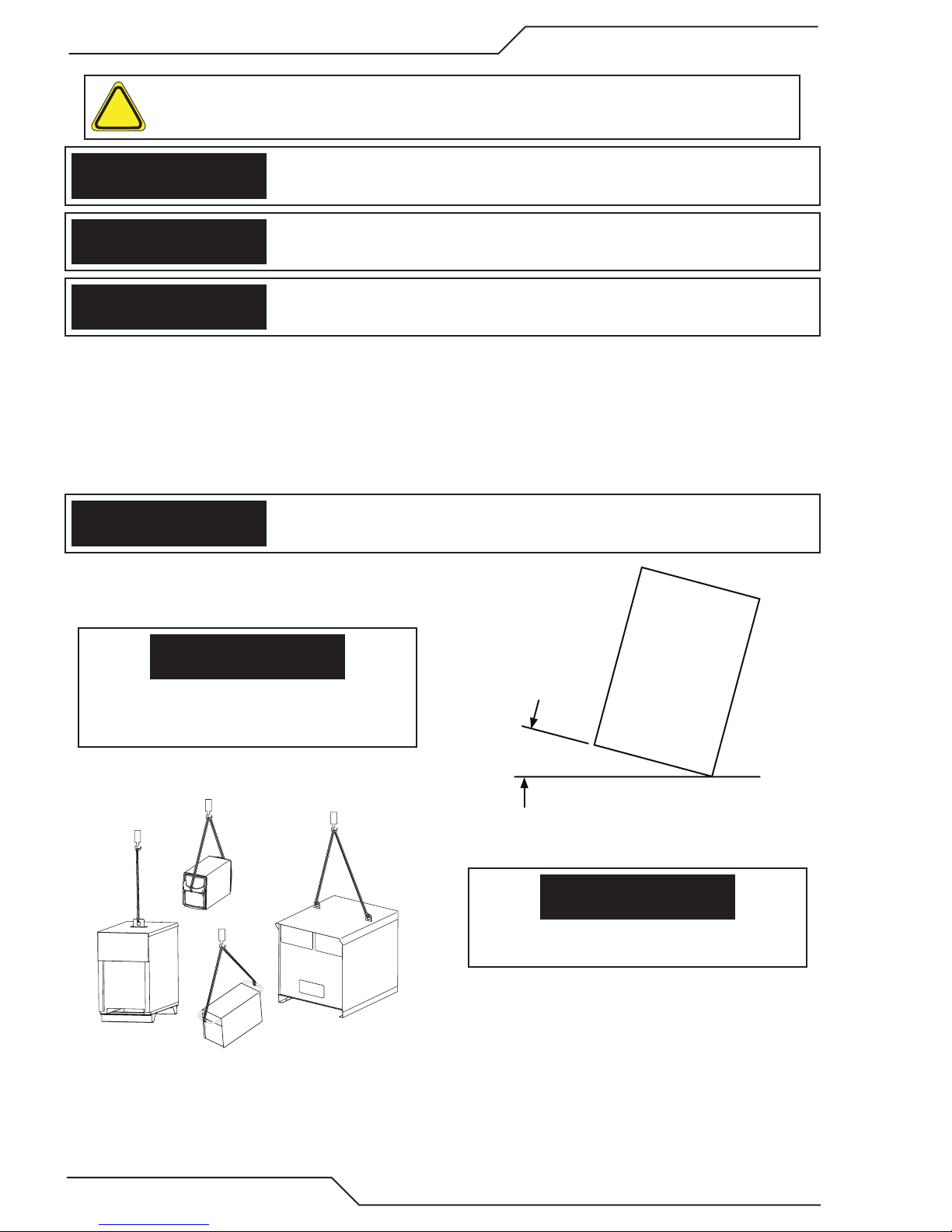
If equipment is placed on a surface that slopes more
than 15°, toppling over may occur. Personal injury and
/ or signicant damage to equipment is possible.
15°
Art# A-12726
To avoid personal injury and/or equipment damage,
lift using method and attachment points shown here.
1-4 SAFETY INSTRUCTIONS Manual 0-5275
Art# A-12736
Page 15

ULTRA-CUT 400 XT
This Page Intentionally Blank
Manual 0-5275 SAFETY INSTRUCTIONS 1-5
Page 16

ULTRA-CUT 400 XT
1.02 Précautions de sécurité - FRENCH CANADIAN
AVERTISSEMENT : Ces règles de sécurité ont pour but d’assurer votre protection. Ils récapitulent les
informations de précaution provenant des références dans la section des Informations de sécurité sup-
!
plémentaires. Avant de procéder à l’installation ou d’utiliser l’unité, assurez-vous de lire et de suivre les
précautions de sécurité ci-dessous, dans les manuels, les fiches d’information sur la sécurité du matériel et sur
les étiquettes, etc. Tout défaut d’observer ces précautions de sécurité peut entraîner des blessures graves ou
mortelles.
PROTÉGEZ-VOUS -- Les processus de soudage, de coupage et de gougeage produisent un niveau
de bruit élevé et exige l’emploi d’une protection auditive. L’arc, tout comme le soleil, émet des rayons
ultraviolets en plus d’autre rayons qui peuvent causer des blessures à la peau et les yeux. Le métal
incandescent peut causer des brûlures. Une formation reliée à l’usage des processus et de l’équipement est essentielle pour prévenir les accidents. Par conséquent:
1. Portez des lunettes protectrices munies d’écrans latéraux lorsque vous êtes dans l’aire de travail, même
si vous devez porter un casque de soudeur, un écran facial ou des lunettes étanches.
2. Portez un écran facial muni de verres filtrants et de plaques protectrices appropriées afin de protéger vos
yeux, votre visage, votre cou et vos oreilles des étincelles et des rayons de l’arc lors d’une opération ou
lorsque vous observez une opération. Avertissez les personnes se trouvant à proximité de ne pas regarder
l’arc et de ne pas s’exposer aux rayons de l’arc électrique ou le métal incandescent.
3. Portez des gants ignifugiés à crispin, une chemise épaisse à manches longues, des pantalons sans
rebord et des chaussures montantes afin de vous protéger des rayons de l’arc, des étincelles et du métal
incandescent, en plus d’un casque de soudeur ou casquette pour protéger vos cheveux. Il est également
recommandé de porter un tablier ininflammable afin de vous protéger des étincelles et de la chaleur par
rayonnement.
4. Les étincelles et les projections de métal incandescent risquent de se loger dans les manches retroussées,
les rebords de pantalons ou les poches. Il est recommandé de garder boutonnés le col et les manches et
de porter des vêtements sans poches en avant.
5. Protégez toute personne se trouvant à proximité des étincelles et des rayons de l’arc à l’aide d’un rideau
ou d’une cloison ininflammable.
6. Portez des lunettes étanches par dessus vos lunettes de sécurité lors des opérations d’écaillage ou de
meulage du laitier. Les écailles de laitier incandescent peuvent être projetées à des distances considérables. Les personnes se trouvant à proximité doivent également porter des lunettes étanches par dessus
leur lunettes de sécurité.
INCENDIES ET EXPLOSIONS -- La chaleur provenant des flammes ou de l’arc peut provoquer un incendie. Le laitier incandescent ou les étincelles peuvent également provoquer un incendie ou une explosion.
Par conséquent :
1. Éloignez suffisamment tous les matériaux combustibles de l’aire de travail et recouvrez les matériaux avec
un revêtement protecteur ininflammable. Les matériaux combustibles incluent le bois, les vêtements, la
sciure, le gaz et les liquides combustibles, les solvants, les peintures et les revêtements, le papier, etc.
2. Les étincelles et les projections de métal incandescent peuvent tomber dans les fissures dans les planchers
ou dans les ouvertures des murs et déclencher un incendie couvant à l’étage inférieur Assurez-vous que
ces ouvertures sont bien protégées des étincelles et du métal incandescent.
3. N’exécutez pas de soudure, de coupe ou autre travail à chaud avant d’avoir complètement nettoyé la
surface de la pièce à traiter de façon à ce qu’il n’ait aucune substance présente qui pourrait produire des
vapeurs inflammables ou toxiques. N’exécutez pas de travail à chaud sur des contenants fermés car ces
derniers pourraient exploser.
4. Assurez-vous qu’un équipement d’extinction d’incendie est disponible et prêt à servir, tel qu’un tuyau
d’arrosage, un seau d’eau, un seau de sable ou un extincteur portatif. Assurez-vous d’être bien instruit
par rapport à l’usage de cet équipement.
1-6 SAFETY INSTRUCTIONS Manual 0-5275
Page 17
ULTRA-CUT 400 XT
5. Assurez-vous de ne pas excéder la capacité de l’équipement. Par exemple, un câble de soudage surchargé
peut surchauffer et provoquer un incendie.
6. Une fois les opérations terminées, inspectez l’aire de travail pour assurer qu’aucune étincelle ou projection de métal incandescent ne risque de provoquer un incendie ultérieurement. Employez des guetteurs
d’incendie au besoin.
7. Pour obtenir des informations supplémentaires, consultez le NFPA Standard 51B, “Fire Prevention in Use
of Cutting and Welding Processes”, disponible au National Fire Protection Association, Batterymarch
Park, Quincy, MA 02269.
CHOC ÉLECTRI QUE -- Le contact avec des pièces électriques ou les pièces de mise à la terre sous
tension peut causer des blessures graves ou mortelles. NE PAS utiliser un courant de soudage c.a. dans
un endroit humide, en espace restreint ou si un danger de chute se pose.
1. Assurez-vous que le châssis de la source d’alimentation est branché au système de mise à la terre de
l’alimentation d’entrée.
2. Branchez la pièce à traiter à une bonne mise de terre électrique.
3. Branchez le câble de masse à la pièce à traiter et assurez une bonne connexion afin d’éviter le risque de
choc électrique mortel.
4. Utilisez toujours un équipement correctement entretenu. Remplacez les câbles usés ou endommagés.
5. Veillez à garder votre environnement sec, incluant les vêtements, l’aire de travail, les câbles, le porteélectrode/torche et la source d’alimentation.
6. Assurez-vous que tout votre corps est bien isolé de la pièce à traiter et des pièces de la mise à la terre.
7. Si vous devez effectuer votre travail dans un espace restreint ou humide, ne tenez vous pas directement
sur le métal ou sur la terre; tenez-vous sur des planches sèches ou une plate-forme isolée et portez des
chaussures à semelles de caoutchouc.
8. Avant de mettre l’équipement sous tension, isolez vos mains avec des gants secs et sans trous.
9. Mettez l’équipement hors tension avant d’enlever vos gants.
10. Consultez ANSI/ASC Standard Z49.1 (listé à la page suivante) pour des recommandations spécifiques
concernant les procédures de mise à la terre. Ne pas confondre le câble de masse avec le câble de mise
à la terre.
CHAMPS ÉLECTRIQUES ET MAGNÉTIQUES — comportent un risque de danger. Le courant électrique
qui passe dans n’importe quel conducteur produit des champs électriques et magnétiques localisés.
Le soudage et le courant de coupage créent des champs électriques et magnétiques autour des câbles
de soudage et l’équipement. Par conséquent :
1. Un soudeur ayant un stimulateur cardiaque doit consulter son médecin avant d’entreprendre une opération
de soudage. Les champs électriques et magnétiques peuvent causer des ennuis pour certains stimulateurs
cardiaques.
2. L’exposition à des champs électriques et magnétiques peut avoir des effets néfastes inconnus pour la santé.
3. Les soudeurs doivent suivre les procédures suivantes pour minimiser l’exposition aux champs électriques
et magnétiques :
A. Acheminez l’électrode et les câbles de masse ensemble. Fixez-les à l’aide d’une bande adhésive lorsque
possible.
B. Ne jamais enrouler la torche ou le câble de masse autour de votre corps.
C. Ne jamais vous placer entre la torche et les câbles de masse. Acheminez tous les câbles sur le même
côté de votre corps.
D. Branchez le câble de masse à la pièce à traiter le plus près possible de la section à souder.
E. Veillez à garder la source d’alimentation pour le soudage et les câbles à une distance appropriée de
votre corps.
Manual 0-5275 SAFETY INSTRUCTIONS 1-7
Page 18

ULTRA-CUT 400 XT
LES VAPEURS ET LES GAZ -- peuvent causer un malaise ou des dommages corporels, plus particulièrement dans les espaces restreints. Ne respirez pas les vapeurs et les gaz. Le gaz de protection
risque de causer l’asphyxie.
Par conséquent :
1. Assurez en permanence une ventilation adéquate dans l’aire de travail en maintenant une ventilation
naturelle ou à l’aide de moyens mécanique. N’effectuez jamais de travaux de soudage, de coupage ou de
gougeage sur des matériaux tels que l’acier galvanisé, l’acier inoxydable, le cuivre, le zinc, le plomb, le
berylliym ou le cadmium en l’absence de moyens mécaniques de ventilation efficaces. Ne respirez pas
les vapeurs de ces matériaux.
2. N’effectuez jamais de travaux à proximité d’une opération de dégraissage ou de pulvérisation. Lorsque
la chaleur ou le rayonnement de l’arc entre en contact avec les vapeurs d’hydrocarbure chloré, ceci peut
déclencher la formation de phosgène ou d’autres gaz irritants, tous extrêmement toxiques.
3. Une irritation momentanée des yeux, du nez ou de la gorge au cours d’une opération indique que la ventilation n’est pas adéquate. Cessez votre travail afin de prendre les mesures nécessaires pour améliorer
la ventilation dans l’aire de travail. Ne poursuivez pas l’opération si le malaise persiste.
4. Consultez ANSI/ASC Standard Z49.1 (à la page suivante) pour des recommandations spécifiques concernant la ventilation.
5. AVERTISSEMENT : Ce produitcontient des produits chimiques, notamment du plomb, reconnu par l’Étatde la Californie pour causerdes malformations congénitaleset d’autresdommages touchant le système
reproductif.
MANIPULATION DES CYLINDRES -- La manipulation d’un cylindre, sans observer les précautions nécessaires, peut produire des fissures et un échappement dangereux des gaz. Une brisure soudaine du
cylindre, de la soupape ou du dispositif de surpression peut causer des blessures graves ou mortelles.
Par conséquent :
Se laver les mainsaprès manipulation.
1. Utilisez toujours le gaz prévu pour une opération et le détendeur approprié conçu pour utilisation sur
les cylindres de gaz comprimé. N’utilisez jamais d’adaptateur. Maintenez en bon état les tuyaux et les
raccords. Observez les instructions d’opération du fabricant pour assembler le détendeur sur un cylindre
de gaz comprimé.
2. Fixez les cylindres dans une position verticale, à l’aide d’une chaîne ou une sangle, sur un chariot manuel,
un châssis de roulement, un banc, un mur, une colonne ou un support convenable. Ne fixez jamais un
cylindre à un poste de travail ou toute autre dispositif faisant partie d’un circuit électrique.
3. Lorsque les cylindres ne servent pas, gardez les soupapes fermées. Si le détendeur n’est pas branché,
assurez-vous que le bouchon de protection de la soupape est bien en place. Fixez et déplacez les cylindres
à l’aide d’un chariot manuel approprié. Toujours manipuler les cylindres avec soin.
4. Placez les cylindres à une distance appropriée de toute source de chaleur, des étincelles et des flammes.
Ne jamais amorcer l’arc sur un cylindre.
5. Pour de l’information supplémentaire, consultez CGA Standard P-1, “Precautions for Safe Handling of
Compressed Gases in Cylinders”, mis à votre disposition par le Compressed Gas Association, 1235 Jefferson Davis Highway, Arlington, VA 22202.
ENTRETIEN DE L’ÉQUIPEMENT -- Un équipement entretenu de façon défectueuse ou inadéquate peut
causer des blessures graves ou mortelles. Par conséquent :
!
1. Efforcez-vous de toujours confier les tâches d’installation, de dépannage et d’entretien à un personnel
qualifié. N’effectuez aucune réparation électrique à moins d’être qualifié à cet effet.
2. Avant de procéder à une tâche d’entretien à l’intérieur de la source d’alimentation, débranchez l’alimentation électrique.
3. Maintenez les câbles, les fils de mise à la terre, les branchements, le cordon d’alimentation et la source
d’alimentation en bon état. N’utilisez jamais un équipement s’il présente une défectuosité quelconque.
1-8 SAFETY INSTRUCTIONS Manual 0-5275
Page 19

ULTRA-CUT 400 XT
DANGER
MISE EN GARDE
AVERTISSEMENT
MISE EN GARDE
4. N’utilisez pas l’équipement de façon abusive. Gardez l’équipement à l’écart de toute source de chaleur,
notamment des fours, de l’humidité, des flaques d’eau, de l’huile ou de la graisse, des atmosphères
corrosives et des intempéries.
5. Laissez en place tous les dispositifs de sécurité et tous les panneaux de la console et maintenez-les en
bon état.
6. Utilisez l’équipement conformément à son usage prévu et n’effectuez aucune modification.
INFORMATIONS SUPPLÉMENTAIRES RELATI VES À LA SÉCURITÉ -- Pour obtenir de l’information supplémentaire sur les règles de sécurité à observer pour l’équipement de soudage à l’arc électrique et le
!
coupage, demandez un exemplaire du livret “Precautions and Safe Practices for Arc Welding, Cutting and
Gouging”, Form 52-529.
Les publications suivantes sont également recommandées et mises à votre disposition par l’American Welding
Society, 550 N.W. LeJuene Road, Miami, FL 33126 :
1. ANSI/ASC Z49.1 - “Safety in Welding and Cutting”.
2. AWS C5.1 - “Recommended Practices for Plasma Arc Welding”.
3. AWS C5.2 - “Recommended Practices for Plasma Arc Cutting”.
4. AWS C5.3 - “Recommended Practices for Air Carbon Arc Gouging and Cutting”.
5. AWS C5.5 - “Recommended Practices for Gas Tungsten Arc Welding“.
6. AWS C5.6 - “Recommended Practices for Gas Metal Arc Welding”.
7. AWS SP - “Safe Practices” - Reprint, Welding Handbook.
8. ANSI/AWS F4.1, “Recommended Safe Practices for Welding and Cutting of Containers That Have Held
Hazardous Substances.”
9. CSA Standard - W117.2 = Safety in Welding, Cutting and Allied Processes.
SIGNIFICATION DES SYMBOLES - Ce symbole, utilisé partout dans ce manuel, signie “Attention” ! Soyez
!
vigilant ! Votre sécurité est en jeu.
Signie un danger immédiat. La situation peut entraîner des blessures graves ou mortelles.
Signie un danger potentiel qui peut entraîner des blessures graves ou mortelles.
Signie un danger qui peut entraîner des blessures corporelles mineures.
Classe de protection de l’enveloppe
L’indice de protection (codification IP) indique la classe de protection de l’enveloppe, c’est-à-dire, le degré de protection contre les corps solides étrangers ou l’eau. L’enveloppe protège contre le toucher, la pénétration d’objets
solides dont le diamètre dépasse 12 mm et contre l’eau pulvérisée à un angle de jusqu’à 60 degrés de la verticale.
Les équipements portant la marque IP21S peuvent être entreposés à l’extérieur, mais ne sont pas conçus pour
être utilisés à l’extérieur pendant une précipitation à moins d’être à l’abri.
Ce produit a été conçu pour la découpe au plasma seulement. Toute autre utilisation pourrait causer des blessures et/ou endommager l’appareil.
Manual 0-5275 SAFETY INSTRUCTIONS 1-9
Page 20

ULTRA-CUT 400 XT
MISE EN GARDE
MISE EN GARDE
L’équipement pourrait basculer s’il est placé sur une
surface dont la pente dépasse 15°. Vous pourriez
vous blesser ou endommager l’équipement de façon
importante.
15°
Art# A-12726
Soulevez à l’aide de la méthode et des points d’attache
illustrés an d’éviter de vous blesser ou d’endommager
l’équipement.
Art# A-12736
1-10 SAFETY INSTRUCTIONS Manual 0-5275
Page 21

ULTRA-CUT 400 XT
SECTION 2: SPECIFICATIONS
2.01 General Description Of The System
A typical Ultra-Cut XT™system configuration includes:
• OnePowerSupply
• RemoteArcStarter
• GasControlModule
• TorchValveAssembly
• PrecisionPlasmaCuttingTorch
• SetOfConnectingLeads
• TorchSparePartsKit
The components are connected at installation.
2.02 Plasma Power Supply
The power supply provides the necessary current for cutting operations. The power supply also monitors system performance,
and cools and circulates the liquid coolant for the torch and leads.
2.03 Remote Arc Starter
This unit produces a temporary HF pulse to start the pilot arc. The pilot arc creates a path for the main arc to transfer to the work.
When the main arc is established, the pilot arc shuts off.
2.04 Gas Control Module
This module allows remote setting of gas selection, pressures, and flows together with setting of cutting current.
2.05 Precision Plasma Cutting Torch
The torch delivers the controlled current to the work through the main arc, causing the metal to be cut.
2.06 Specifications & Electrical Requirements
Ultra-Cut 400 XT™ Specifications & Design Features
Max OCV (U0) 425 vdc
Minimum Output Current 5 Amps
Max Output Current 400 Amps
Output Voltage 60 - 200 vdc
400 Amp System
Duty Cycle Rating 100% @ 400A, 200V, (80kW),
Ambient Temperature
for Duty Cycle Rating
Operating range 14°F to 122°F (-10°C to + 50°C)
Power Factor 0.94 @ 400 A DC Output
Cooling Coolant and Forced Air (Class F)
104F° (40°C)
Input Power Input Current Suggested Sizes (See Note)
Voltage Freq. 3-Ph 3-Ph Fuse (Amps) Wire (AWG) Wire (mm2)
(Volts) (Hz) (kVA) (Amps) 3-Ph 3-Ph 3-Ph
480 50/60 93 114 175 #3 35
Manual 0-5275 SPECIFICATIONS 2-1
Ultra-Cut 400 XT™ Power Supply
Page 22

ULTRA-CUT 400 XT
NOTE!
* Suggested wire size based on United States NFPA 70 National Electrical Code 2011 edition
published by the National Fire Prevention Association. Listings are from table 400.5(A)(2) for flexible cord of certain types rated for 75 deg C in ambient temperatures up to 30 deg C. Using wires
of lower temperature rating or different insulation type may require larger wire size. De rate for
higher ambient.
These are suggestions only. Always refer to your local and national codes that apply to your region
for final determination of correct wire type and size.
2.07 Power Supply Dimensions
27.6 inch
701 mm
35.97 inch
914 mm
Art # A-11982
47.77 inch
1213 mm
400A 580 lb / 263 kg
2-2 SPECIFICATIONS Manual 0-5275
Page 23

ULTRA-CUT 400 XT
2.08 Power Supply Rear Panel Features
GCM Connector
CNC Connector
C.C.M.
Arc Starter Connector
H.E. Connector
Fuse
Customer
Optional
Ports
TSC/Comm
J55 - GCM
USER INPUT
J15 - CNC
HEIGHT CONTROL
J54 - TSC /COMM
J59 - RAS
CB2 - 5A 120 VAC
CB3 - 5A 24 VAC
J70 - HE
CB4 - 5A 120 VAC
F1 - 8A SB 230 VAC F2 - 8A SB 230 VAC
Circuit Breakers
Coolant Return
Coolant Supply
AC Power Lamp
Pilot Lead
Work Lead
Negative Return
Coolant Filter
Input Power
Ports
Art # A-11842_AB
Manual 0-5275 SPECIFICATIONS 2-3
Page 24

ULTRA-CUT 400 XT
2.09 Gas Requirements
The customer will provide all gases and pressure regulators. Gases must be of high quality. Pressure regulators shall be double
stage and installed within 3 meters from the Gas Console.
Ultra-Cut 400 XT™ Power Supply: Gas Pressures, Flows, and Quality Requirements
Gas Quality Minimum Pressure Flow
O2 (Oxygen) 99.5% Purity
(Liquid recommended)
N2 (Nitrogen) 99.5% Purity
(Liquid recommended)
<1000 ppm O2, <32 ppm
H2O)
Compressed
or Bottled Air
H35 (Argon-Hydrogen)
H35 = 35% Hydrogen,
Clean, Dry,
Free of Oil (see Note 1)
99.995% Purity
(gas recommended)
65% Argon
H17 17.5% Hydrogen
32.5% Argon
99.995% Purity
(gas recommended)
50% Nitrogen
H2O (Water) See Note 2 55 psi (3.8 bar) 10 gph (0.6 lpm)
Note 1: The air source must be adequately filtered to remove all oil or grease. Oil or grease
contamination from compressed or bottled air can cause fires in conjunction with oxygen.
For filtering, a coalescing filter able to filter to 0.01 microns should be placed as close as
possible to the gas inlets on the Gas Control Module.
Note 2: The tap water source does not need to be deionized, but in water systems with extremely high mineral content a water
softener is recommended. Tap water with high levels of particulate matter must be filtered.
Note 3: Water Pressure Regulator No. 8-6118 is recommended to ensure proper water pressure.
120 psi
8.3 bar / 827 kPa
200 scfh (95 lpm)
120 psi
8.3 bar / 827 kPa
120 psi
8.3 bar / 827 kPa
300 scfh (141.6 lpm)
500 scfh (236 lpm)
120 psi
8.3 bar / 827 kPa 200 scfh (95 lpm)
120 psi
8.3 bar / 827 kPa 200 scfh (95 lpm)
2.10 Gas Applications
MATERIAL MILD STEEL STAINLESS STEEL ALUMINUM
GAS TYPE GAS TYPE GAS TYPE
OPERATION PREFLOW PLASMA SHIELD PREFLOW PLASMA SHIELD PREFLOW PLASMA SHIELD
30A Cut
50A Cut
70A Cut
100A Cut
150A Cut
200A Cut
250A Cut Air O
300A Cut
400A Cut
Air O
Air O
Air O
Air O
Air O
Air O
Air O
Air O
2
2
2
2
2
2
2
2
2
2-4 SPECIFICATIONS Manual 0-5275
O
2
Air Air Air Air Air Air Air
Air Air Air Air Air Air Air
Air N
Air N
Air N
Air
Air N
Air N
Air Air Air Air Air Air
N
2
N
2
N
2
2
N
2
2
N
2
2
N
2
2
N
2
2
N
2
N
2
N
2
N
2
N
2
H35 N
N
2
H35 N
N
2
H35 N
N
2
H35 N
N
2
H35 N
N
2
H17 N
H20 N
H20 N
H20 N
2
H20 N
2
H20 N
2
H20 N
2
H20 N
2
H20 N
2
2
2
2
N
2
2
N
2
2
N
2
2
N
2
2
N
2
2
N
2
N
2
N
2
N
2
H35 N
N
2
H35 N
N
2
H35 N
N
2
H35 N
N
2
H35 N
N
2
H17 N
H20
H20
H20
H20
H20
H20
H20
H20
2
2
2
2
2
2
Page 25

ULTRA-CUT 400 XT
2.11 XT Torch Specifications
A. Torch Dimensions
Basic 400 Amp torch dimensions
Basic 100 Amp torch dimensions
2”
50.8 mm
168.5 mm
6.6”
4.3”
109.1 mm
2.4”
61 mm
70°
1.4”
34.5 mm
.5”
12.7 mm
Art # A-09534
2.25"
End Cap
19"
57.15 mm
482.7 mm
Mounting Tube
2.0"
50.8 mm
15.5"
393.8 mm
6.3"
160.1 mm
2.4"
61 mm
3.98"
101.1 mm
2.7"
69.6 mm
1.6"
40. mm
1.49"
37.8 mm
Manual 0-5275 SPECIFICATIONS 2-5
Page 26
ULTRA-CUT 400 XT
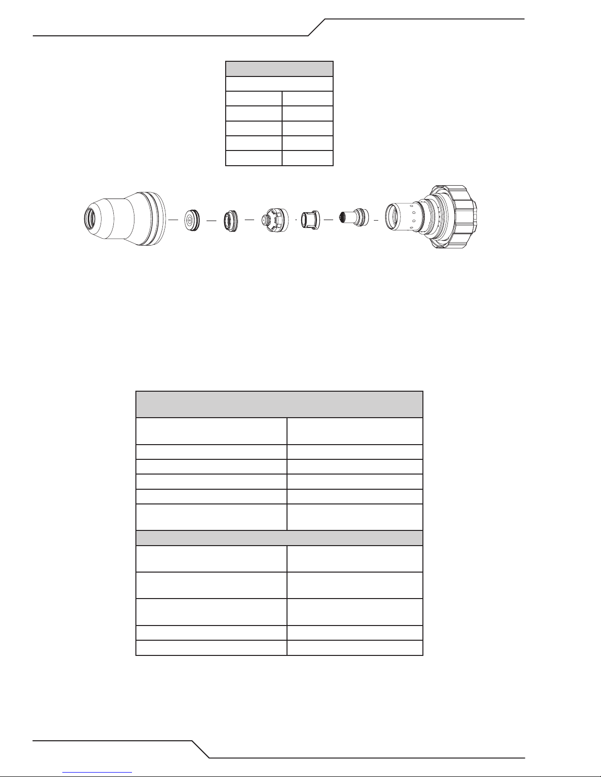
Cartridge
Shield Cup
Art # A-04741
Electrode
Tip
Plasma Gas
Distributor
Shield Gas
Distributor
Shield Cap
B. Torch Leads Lengths
Torch Lead Assembly
Lengths
Feet Meters
10 3.05
15 4.6
25 7.6
50 15.2
C. Torch Parts (Generic Parts Shown)
D. Parts - In - Place (PIP)
The torch is designed for use with a power supply which senses coolant return flow to confirm that torch parts are in place.
If coolant return flow to the power supply is absent or insufficient the power supply will not provide power to the torch.
Coolant leakage from the torch also indicates that torch parts are absent or installed improperly.
E. Type of Cooling
Combination of gas stream through torch and liquid cooling.
F. XT Torch Data
for use with Ultra-Cut 400 XT™ Power Supply
Ambient
Temperature
Duty Cycle 100% @ 400 Amps
Maximum Current 400 Amps
Voltage (Vpeak) 500V
Arc Striking Voltage 10kV
Current Up to 400 Amps, DC,
XT Torch Gas Specifications
Plasma Gases: Compressed Air, Oxygen,
Shield Gases: Compressed Air, Oxygen,
Operating Pressure 125 psi ± 10 psi
Maximum Input Pressure 135 psi / 9.3 bar
Gas flow 10 - 500 scfh
XT Torch Ratings
104° F
40° C
Straight Polarity
Nitrogen, H35, H17,
Nitrogen, Water, H35
8.6 bar ± 0.7 bar
2-6 SPECIFICATIONS Manual 0-5275
Page 27

ULTRA-CUT 400 XT
SECTION 3: INSTALLATION
3.01 Installation Requirements
Electric Supply
The electrical supply network, the gas and water supply system must meet local safety standards. This conformity shall
be checked by qualified personnel.
Ultra-Cut 400 XT™ Power Supply
Input Power Input Current Suggested Sizes (See Note)
Voltage Freq. 3-Ph 3-Ph Fuse (Amps) Wire (AWG) Wire (mm2)
(Volts) (Hz) (kVA) (Amps) 3-Ph 3-Ph 3-Ph
480 50/60 93 114 175 #3 35
NOTE!
* Suggested wire size based on United States NFPA 70 National Electrical Code 2011 edition
published by the National Fire Prevention Association. Listings are from table 400.5(A)(2) for
flexible cord of certain types rated for 75 deg C in ambient temperatures up to 30 deg C. Using wires of lower temperature rating or different insulation type may require larger wire size.
Derate for higher ambient.
These are suggestions only. Always refer to your local and national codes that apply to your
region for final determination of correct wire type and size.
Gas Supply
The customer must supply all gases and pressure regulators. Gases must be of high quality. Pressure regulators must
be double-stage and installed as close as possible to the gas console. Contaminated gas can cause one or more of the
following problems:
• Reducedcuttingspeed
• Poorcutquality
• Poorcuttingprecision
• Reducedconsumableslife.
• Oilorgreasecontaminationfromcompressedorbottledaircancauseresinconjunctionwithoxygen.
Cooling System Requirements
Coolant must be added to the system on installation. The amount required varies with torch leads length.
Victor Thermal Dynamics recommends the use of its coolants 7-3580 and 7-3581 (for low temperatures).
Coolant Capabilities
Cat. Number and Mixture Mixture Protects To
7-3580 ‘Extra-Cool™’ 25 / 75 10° F / -12° C
7-3581 ‘Ultra-Cool™’ 50 / 50 -27° F / -33° C
7-3582 ‘Extreme Cool™’ Concentrate* -76° F / -60° C
* For mixing with D-I Cool™ 7-3583
Manual 0-5275 INSTALLATION 3-1
Page 28

ULTRA-CUT 400 XT
3.02 System Layout
Refer to section 3.04 for ground connections and ground cables.
175’ / 53.3 m Maximum Length
F1
Primary power
CNC
Art # A-11940
P
Pilot Return #8
Coolant Supply 10’
Coolant Return 10’
Control Cable
Ultra-Cut
XT Power
Supply
Fiber
Optic
Cable
Control
Cable
125’ / 38.1 m Maximum Length
Negative Cable
Control Cable
C
HE 400
D
Heat
Exchanger
Y
L
Gas Control
Module
K
F
Coolant Supply
Coolant Return
Plasma Gas
Shield Gas
Preflow Gas
Control
Cable
Water
Shield
A
B
E
F1
H
Q
R
S
T
Remote
C
D
Torch
Valve
Assembly
Work Cable
50’ / 15.25 m Maximum Length
Pilot Return
Arc
Starter
Coolant Supply
Coolant Return
Plasma Gas
Shield Gas
Shield
Shield
Positioning Tube
I
G
J
Torch
Work
175’ / 53.3 m Maximum Length
3-2 INSTALLATION Manual 0-5275
Page 29

ULTRA-CUT 400 XT
3.03 Recommended Gas Supply Hose
Item # Qty Description Catalog #
1 3/8”Gray Synflex Hose. No fittings included. Catalog number per foot 9-3616
3.04 Leads and Cables All Amperage
A
B
C
D
E,Y
14/7
F
F1
G
Green
Red
#8 AWG Cable
3/0 AWG Cable (95 mm
Green / Yellow # 4 AWG
Green / Yellow 1/0 (50 mm )
Pilot Return, Power Supply
to Arc Starter
2
)
Green
Red
2
Negative Lead, Power Supply
to Arc Starter
Coolant Supply Lead,
Power Supply to Arc Starter
Coolant Return Lead,
Power Supply to Arc Starter
E - Control Cable, Power Supply
to Arc Starter
Y - Control Cable to Heat Exchanger
Ground Cable
Ground Cable,
Remote Arc Starter
To Earth Ground
Shielded Torch Lead
Assembly, Remote
Arc Starter to Torch
Art # A-11873_AB
I
J
K
L
H, Q,
R, S,T
O
P
37
37
3/0 (95 mm ) Cable
2
Plasma Gas Lead,
Torch Valve to Torch
Shield Gas Lead,
Torch Valve to Torch
Control Cable,
Power Supply to
Gas Control Module
Fiber Optic Cable,
Power Supply to
Gas Control Module
Work Cable
CNC Cable (37 Wire)
Manual 0-5275 INSTALLATION 3-3
Page 30

ULTRA-CUT 400 XT
3.05 Lift the Power Supply
WARNING
Do not touch live electrical parts.
Disconnect input power conductors from de-energized supply line before moving
unit.
FALLING EQUIPMENT can cause serious personal injury and equipment damage.
Use a forklift, crane, or hoist to lift the unit off the shipping pallet as shown. Keep the power supply steady and vertical. Do not
lift it any further than necessary to clear the shipping pallet. Ensure all panels and screws are secure prior to lifting.
Art # A-11531_AC
Set the power supply on a solid, level surface. The installer may fasten the power supply to the floor or a supporting fixture
with hardware passing through the horizontal parts of the power supply feet.
3-4 INSTALLATION Manual 0-5275
Page 31

ULTRA-CUT 400 XT
3.06 Connect Input Power and Ground Cables
Connect Input Power and System Ground Cables
1. Remove the input power cover to the right of the coolant filter at the rear of the power supply. To do this remove the two
screws then lift up and pull away.
2. Carefully cut back the outer sheath on the primary input power cable to expose the individual wires. Cut back the insulation on the individual wires. Route the cable upward through Input Power Port at the bottom of the panel. There are 2
extra plates included at the cable entrance. Discarding one or both allows changing the opening size for larger cable/
strain relief.
3. Install stripped end of 3 phase wires into the terminal block L1, L2 and L3 and connect the individual cables as shown.
4. Connect the power cable ground wire to the ground terminal block.
5. Route a system ground cable (F1) through the last opening in the connections cover support panel next to the input power
cable. Connect the cable to the ground terminal block on the power supply rear panel. Refer to the Ground Connections
Section for full details and procedures on proper system grounding.
Art # A-11970
Ground Terminals
F1 Ground
Input Power
Manual 0-5275 INSTALLATION 3-5
Page 32

ULTRA-CUT 400 XT
3.07 Connect Work Cable and Pilot and Negative Leads
1. Remove the output power cover to the left of the coolant filter at the rear of the power supply. To do this remove the two
screws then lift up and pull away.
2. Route the ends of the work cable, pilot and negative/torch leads upward through the leads strain relief at the bottom edge
of the left rear panel.
3. Refer to the illustration. Connect the leads as shown. Tighten securely. Do not overtighten.
+
-
Pilot
Work Cable
Torch
Art # A-11533
4. Reinstall the cover on the power supply. Snug the hardware securely by hand. Do not overtighten.
3-6 INSTALLATION Manual 0-5275
Page 33

ULTRA-CUT 400 XT
3.08 Ground Connections
Star Ground on Cutting Table
Remote Arc
Starter (RAS-1000)
Cutting Machine / Gantry
Cutting Table
1/0
Ground Cable
(F1)
Ground Cable
Customer supplied
Earth Ground
Rod
A good ground will be
less than 3 ohm. Ideal 1.
Torch
1/0
0 - 10 ft (0 - 3 m) Ideal
20 ft (6 m) Maximum
See
Manufacturer
CNC
Device
Gas Control Module
Primary location
#4 AWG
Ground
(F)
3/0 Work Cable
1/0 Ground Cable
Power Supply
‘Star’
Ground
Note: The gas control module can
be mounted on top of the power
supply.
If it is, it should be grounded
directly to the power supply with
#4 AWG ground, (F).
Any location requires grounding
the power supply to the
‘Star’ ground with the 1/0
Ground Cable (F1).
Art # A-11875.AB
A. Electromagnetic Interference (EMI)
Pilot arc starting generates a certain amount of electromagnetic interference (EMI), commonly called RF noise. This RF noise
may interfere with other electronic equipment such as CNC controllers, remote controls, height controllers, etc. To minimize RF
interference, follow these grounding procedures when installing automation (mechanized) systems:
B. Grounding
1. The preferred grounding arrangement is a single point or “Star” ground. The single point, usually on the cutting table, is
connected with 1/0 AWG (European 50 mm2) or larger wire to a good earth ground (measuring less than 3 ohms; an ideal
ground measures 1 ohm or less. Refer to paragraph ‘C’, Creating An Earth Ground. The ground rod must be placed as close
as possible to the cutting table, ideally less than 10 ft (3.0 m), but no more than 20 ft (6.1 m) from the cutting table.
NOTE!
All ground wires should be as short as possible. Long wires will have increased
resistance to RF frequencies. Smaller diameter wire has increased resistance to RF
frequencies, so using a larger diameter wire is better.
2. Grounding for components mounted on the cutting table (CNC controllers, height controllers, plasma remote controls, etc.)
should follow the manufacturer’s recommendations for wire size, type, and connection point locations.
For Thermal Dynamics components (except Remote Arc Starter and Gas Control Module) it is recommended to use a minimum
of 10 AWG (European 6 mm2) wire or flat copper braid with cross section equal to or greater than 10 AWG connected to the
cutting table frame. The Remote Arc Starter uses 1/0 earth ground wire and the Gas Control Module should use minimum #
4 AWG wire. The connection point must be to clean bare metal; rust and paint make poor connections. For all components,
wires larger than the recommended minimum can be used and may improve noise protection.
3. The cutting machine frame is then connected to the “Star” point using 1/0 AWG (European 50 mm2) or larger wire.
4. The plasma power supply work cable (see NOTE) is connected to the cutting table at the single point “Star” ground.
NOTE!
Do Not connect the work cable directly to the ground rod. Do not coil up excess
ground or power cables. Cut to proper length and reterminate as needed.
Manual 0-5275 INSTALLATION 3-7
Page 34

ULTRA-CUT 400 XT
5. Make sure work cable and ground cables are properly connected. The work cable must have a solid connection to the cutting
table. The work and ground connections must be free from rust, dirt, grease, oil and paint. If necessary grind or sand down
to bare metal. Use lock washers to keep the connections tight. Using electrical joint compound to prevent corrosion is also
recommended.
6. The plasma power supply chassis is connected to the power distribution system ground as required by electrical codes. If
the plasma supply is close to the cutting table (see NOTE) a second ground rod is not usually needed, in fact it could be
detrimental as it can set up ground loop currents that cause interference.
When the plasma power supply is far away from the ground rod and interference is experienced, it may help to install a second
earth ground rod next to the plasma power supply. The plasma power supply chassis would then be connected to this ground
rod.
NOTE!
It is recommended that the Plasma Power Supply be within 20 - 30 ft (6.1 – 9.1 m)
of the cutting table, if possible.
7. The plasma control cable should be shielded with the shield connected only at the cutting machine end. Connecting the shield at both ends will allow ground loop currents which may cause more interference than with no
shield at all.
Creating An Earth Ground
1. To create a solid, low resistance, earth ground, drive a 1/2 in (12 mm) or greater diameter copper clad ground rod at least 6 - 8
ft (1.8 - 2.4 m) into the earth so that the rod contacts moist soil over most of its length. Depending on location, a greater depth
may be required to obtain a low resistance ground (see NOTE). Ground rods, typically 10 ft (3.0 m) long, may be welded end
to end for greater lengths. Locate the rod as close as possible to the work table. Install a ground wire, 1/0 AWG (European
50 mm2) or greater, between the ground rod and the star ground point on the cutting table.
NOTE!
Ideally, a properly installed ground rod will have a resistance of three ohms or less.
D. Low Cost Ground Rod Tester
1. A key component of reduced EMI is a good low resistance earth ground rod. There are several very expensive instruments
to measure the ground but cost from several hundred to a few thousand dollars. Below is a low cost alternative which can
be constructed by qualified personnel familiar with established electrical construction and safety practices. Previously suggested method using an incandescent light bulb will not work with GFCI outlets which are increasingly being used and the
bulbs are becoming obsolete.
2. This method, as well as the light bulb method and some of the expensive instruments, assumes the utility ground is perfect,
Zero ohms. It connects the rod being tested in series with the utility ground and measures the resistance of both in series.
If the utility ground is not zero ohms, no matter how good your rod is, you won’t get a low reading due the higher resistance
of the utility ground. Fortunately this is rare. Also if your rod is right next to another earth grounded structure you may get a
false lower reading of only resistance between that structure and your rod rather than to gnd.
NOTE!
In the United States most standard AC outlets are 120 VAC 60 Hz. Elsewhere most
outlets are 220 VAC 50Hz.
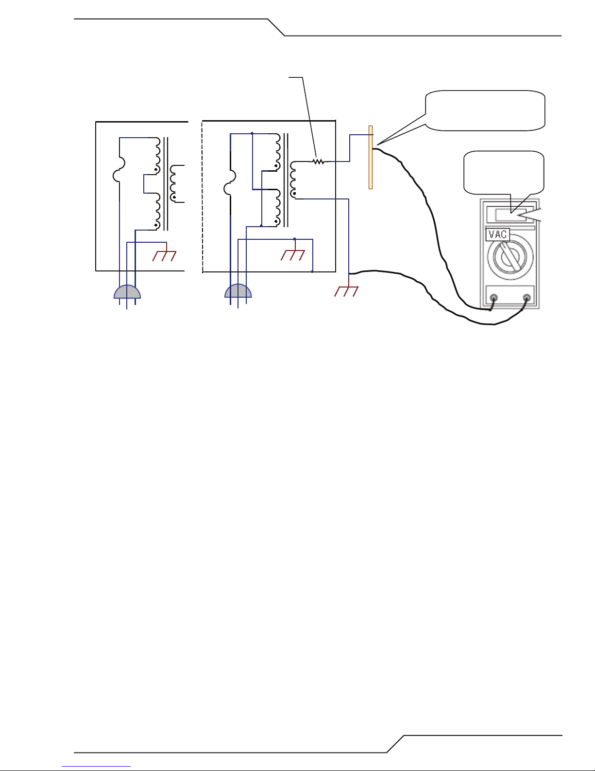
3. Obtain a transformer rated for at least 25 VA with primary voltage and frequency matching your standard outlets. The transformer should have an isolated secondary of either 220 VAC (220 -240 is OK) or 120 VAC (110-120 is OK) and be rated for
at least 100 ma. The transformer could also have dual 115VAC primaries wired in series for 220V or in parallel for 120 VAC.
An example is Triad N-68X, shown below, rated 50VA, 50/60 Hz.
Obtain a power resistor of either 1200 (1.2K) ohms, 15-25W min, if using a 120V secondary or 2200 (2.2K) ohms, 25 -30W
for a 220V secondary.
4. Assemble the transformer and power resistor in a metal box. Connect a 3 wire (w/gnd) power cord with ground wire attached
to the metal box for safety. If a plastic box is used instead, connect the transformer core and the resistor mounts to the power
cord ground wire. There should be a fuse ¼ - ½ A, in series with the transformer primary. From the transformer secondary
connect one wire to the utility safety ground. This could be the cutting table frame, the ground terminal of the 120 or 220 VAC
outlet or the test box if grounded as indicated.
3-8 INSTALLATION Manual 0-5275
Page 35
ULTRA-CUT 400 XT
An excellent ground measures 1 ohm or less. Up to 3 ohms is often acceptable, higher reduces the effectiveness of the EMI
suppression.
R = 1.2K, 15W
Triad N-68X
115 VAC 115 VAC
(2.2K, 25W for 220 VAC)
Triad N-68X
115 VAC
Ground Rod with other
connecons removed
F
GND
220 VAC
F
115 VAC
115 VAC
GND
120 VAC
Utility (building) GND
Art # A-12710
0.1 VAC = 1 OHM,
0.3 VAC = 3 OHM,
etc.
5. Increasing the ground rod length beyond 20 - 30 ft (6.1 – 9.1 m) does not generally increase the effectiveness of the ground
rod. A larger diameter rod which has more surface area may help. Sometimes keeping the soil around the ground rod moist
by continuously running a small amount of water into it will work. Adding salt to the soil by soaking it in salt water may also
reduce its resistance. You may also try a chemical ground rod devise. When these methods are used, periodic checking of
the ground resistance is required to make sure the ground is still good.
E. Routing Of Torch Leads
1. To minimize RF interference, position torch leads as far as possible from any CNC components, drive motors, control cables,
or primary power lines. If cables have to pass over torch leads, do so at an angle. Do not run the plasma control or other
control cables in parallel with the torch leads in power tracts.
2. Keep torch leads clean. Dirt and metal particles bleed off energy, which causes difficult starting and increased chance of RF
interference.
Manual 0-5275 INSTALLATION 3-9
Page 36

ULTRA-CUT 400 XT
3.09 Connect Coolant Leads
1. Connect the color-coded coolant hoses to the coolant connections on the power supply rear panel. The supply line (out)
is flagged green, the return line (in) is flagged red.
J55 - GCM
USER INPUT
J15 - CNC
HEIGHT CONTROL
J54 - TSC /COMM
J59 - RAS
CB2 - 5A 120 VAC
CB3 - 5A 24 VAC
J70 - HE
CB4 - 5A 120 VAC
F1 - 8A SB 230 VAC F2 - 8A SB 230 VAC
COOLANT
RETURN SUPPLY
Coolant Connections
RED
GREEN
To HE-400 Heat Exchanger
Art # A-11992
3-10 INSTALLATION Manual 0-5275
Page 37

ULTRA-CUT 400 XT
3.10 Connect Cables for CNC, Remote Arc Starter, GCM and HE 400
1. Connect one end of each cable to the power supply.
2. Connect the other end of the CNC cable to the CNC device.
3. The CNC cable shield must be attached to ground at the CNC end.
J55 - GCM
J55 To GCM
J15 To CNC Control
J59 To Remote
Arc Starter
USER INPUT
J15 - CNC
HEIGHT CONTROL
J54 - TSC /COMM
J59 - RAS
CB2 - 5A 120 VAC
CB3 - 5A 24 VAC
J70 - HE
CB4 - 5A 120 VAC
F1 - 8A SB 230 VAC F2 - 8A SB 230 VAC
J54 TSC/
Comm
J70 To Heat
Exchanger
Art # A-11971
Manual 0-5275 INSTALLATION 3-11
Page 38

ULTRA-CUT 400 XT
Hose
Strain Relief
Fiber
Connector with Latch
Protective End Covers
Art # A-09416
3.11 Handling and Installation of Fiber Optics
General Information
This kit is for proper handling and installation of Fiber Optic Cables used in Thermal Dynamics Ultra-Cut® and Auto-Cut O2®
automated gas boxes and Gas Control Modules.
Fiber Optic cable is used in place of wire because it offers far superior immunity to electrical noise but it is more delicate and
requires careful handling. With fiber optics, electrical signals are converted to light with a transmitter LED. The light passes down
the fiber where it is converted back to an electrical signal at the receiver end. Any damage to the fiber from sharp bends or pulling
that stretches the fiber can reduce it’s ability to transmit light. We run the fiber inside a hose for most of its length to protect it
from abrasion, burning from hot metal or sharp bends but the ends are exposed and must be handled with care.
Remove fiber optic end covers and plugs.
WARNING
Disconnect primary power at the source.
Art # A-12015
3-12 INSTALLATION Manual 0-5275
Page 39

ULTRA-CUT 400 XT
Art # A-09417
Art # A-09418
Avoid the following:
1. If you need to pull the cable through a power track do not fold the fiber back on itself making a sharp bend where it exits
the hose.
2. Don’t hook onto the fiber to pull on the cable.
3. Once the fiber cable is installed in the CCM or gas control make sure the strain relief nut is securely tightened onto the
hose so the hose can’t pull out of it like this:
Hose not secured in
the Strain Relief
Art # A-09677_AB
Manual 0-5275 INSTALLATION 3-13
Page 40
ULTRA-CUT 400 XT
Art # A-09420
No
bends
Correct installation:
Correct way to pull the cable is to use a snake or a wire or another cable and attach it securely to the hose behind the strain relief.
Then secure the fiber connector to the pulling device leaving some slack in the fiber. Keep the protective end covers on the fiber
until you are ready to connect it to the PCB in the CCM or gas control.
Correct installation in CCM or Gas Control leaves a loop of fiber so there is no stress on the fiber where it exits the connector or
the hose.
CCM
No
Sharp
sharp
Bends
Art # A-12014
3-14 INSTALLATION Manual 0-5275
Page 41

ULTRA-CUT 400 XT
3.12 Set Switches on the Command - Control Module
Remove the power supply upper right side. Set switches on the CCM (Command-Control Module) per the illustrations. Switch
settings and connection details are provided in the Appendix. Any changes made require a restart of the power supply.
CAUTION
!
O
N
1
SW 8-1: Pilot Time 1 = OFF = Short (85 ms.) (Factory default setting).
1 = ON = Long (3 s.)
SW 8-2: Remote Current 1 = OFF = Disabled (Factory default setting).
1 = ON = (Remote Analog Current Control) Also set SW11 to “A” position
*SW 8-3: Auto Transfer Retry1 = OFF = Enabled Up to 3 tries (Factory default setting).
1 = ON = Disabled
SW 8-4: OFF = Disabled (Factory default setting).
ON = Remote Marking SW Enabled at TB3-1&2
SW-1-1: Auto Pilot Restart. 1 = ON = Auto Pilot Function enabled.
1 = OFF = Auto Pilot Function disabled (Factory default setting).
SW-1-2: Pilot Delay 2 = OFF, 3 = OFF, 4 = OFF: 0 Seconds (Factory default setting).
SW-1-3: Pilot Delay 2 = ON, 3 = OFF, 4 = OFF: 0.1 Seconds
SW-1-4: Pilot Delay 2 = OFF, 3 = ON, 4 = OFF: 0.2 Seconds
2 = ON, 3 = ON, 4 = OFF: 0.4 Seconds
2 = OFF, 3 = OFF, 4 = ON: 0.8 Seconds
2 = ON, 3 = OFF, 4 = ON: 1.0 Seconds
2 = OFF, 3 = ON, 4 = ON: 1.5 Seconds
2 = ON, 3 = ON, 4 = ON: 2.0 Seconds
SW-5-1: Tip Saver Reserved for Factory use.
SW-5-2: Off Plate Reserved for Factory use.
SW-4: Postflow Time 1 = OFF, 2 = OFF: 10 Seconds (Factory default setting).
1 = ON, 2 = OFF: 20 Seconds
1 = OFF, 2 = ON: 5 Seconds
1 = ON, 2 = ON: 0 Seconds
SW-3: Gas Preflow Time 1 = Off, 2 = OFF: 3 seconds
1 = ON, 2 = OFF: 4 seconds
1 = OFF, 2 = ON: 6 seconds
1 = ON, 2 = ON: 8 seconds
3
2
Printed circuit boards in the Command - Control Module are static
- sensitive. Discharge any built-up static charges in your body or
surroundings before touching the printed circuit boards.
Future Use
SW1 SW3SW4SW5SW8
4
1
2
Switches shown in OFF position
4
3
1
SW9
2
1
1
2
2
USB
1
O
N
2
Actual orientation
Active only when
SW-1-1 is set to ON.
Art # A-11890_AB
O
N
1
2
3
4
1
Switches shown in OFF position
2
SW1 SW3SW4SW5SW8
3
4
1
2
1
SW9
2
1
2
1
2
O
N
Manual 0-5275 INSTALLATION 3-15
Page 42

ULTRA-CUT 400 XT
CAUTION
!
Printed circuit boards in the Command - Control Module are static
- sensitive. Discharge any built-up static charges in your body or
surroundings before touching the printed circuit boards.
SW11
SW6
SW12
SW13
SW-6: OK-to-Move: Contact closure, 120VAC @ 1A (Factory default setting) or
DC Volts (16-18vdc@ up to 100 ma.)
SW-11: Set “B” position, (up) for default
SW-11: Set “A” position (down) for remote analog current control. SW-8-2 must be set to “ON”.
SW-12-1/2/3/4: Divided Arc signal
1 = ON = 16.6:1
2 = ON = 30:1
3 = ON = 40:1
4 = ON = 25:1
SW13: Ultra-Cut Switch positions
All = OFF = 50:1 (Factory default setting)
Only 1 on at a time.
4
Art # A-12016_AB
3-16 INSTALLATION Manual 0-5275
3
2
1
ON
Page 43

ULTRA-CUT 400 XT
3.13 Height Control Connections
The terminal strip provides connections to negative Arc Volts (Torch or electrode), Tip Volts (Pilot) and Work. These are for
a height control that requires connection to the full non-divided arc voltage. Also available on the terminal strip are 120VAC
and 24 VAC. The allowable current draw is 100ma @ 120VAC and 1Amp @ 24 VAC.
Art # A-11900
TB4
NOTE!
1 2 3 4 5 6 7
24 VAC
@ 1A
Art # A-11954
120 VAC
@ 100 ma.
Work
Tip Volts
(Pilot)
Arc Volts
(Torch)
There are holes added in the rear panel for customer wiring. This, rather than the one
in the CCM will be the preferred place for customer added wiring (and strain relief)
for connections to height controls, etc..
Manual 0-5275 INSTALLATION 3-17
Page 44

ULTRA-CUT 400 XT
Art # A-07962
8.50”
215.90mm
0.28”
7.14mm
11.00”
279.40mm
16.18”
410.97mm
13.68”
347.47mm
Gas Box
3.14 Gas Control Module Installation
The Gas Control Module must be installed in a suitable location where it is easily accessible to the system operator.
The unit must be mounted to a flat horizontal surface. If the Module is mounted to a gantry or to any other support
subject to vibration or motion, the installer must fasten the module to the support securely.
The Module should be located as far away as possible from the Arc Starter due to electromagnetic interference. It
is acceptable to locate the control cable in the same track as the cables from the Arc Starter.
The Module includes feet which lift the bottom panel off the mounting surface. There are ventilation holes on the
bottom panel; the space between the bottom panel and the mounting surface must remain open for ventilating air
to enter the module. Louvers on the back panel of the module must also remain unblocked, for the free passage
of ventilating air.
Mounting Dimensions
NOTE
Height not shown is 14.125” (359 mm)
3-18 INSTALLATION Manual 0-5275
NOTE!
The unit must be mounted so that the Flowmeters are plumb. If the Flowmeters are
not plumb, incorrect flow indications may occur.
Page 45

ULTRA-CUT 400 XT
Art # A-06882
Gas Control Module Cover
Do not remove
Remove Ground
Wire
Preparation
1. Remove the screws securing the Cover Panel to the Module.
2. Carefully remove the cover from the module noting the attached ground wire. Remove the ground wire if
needed.
Cover Removal
Manual 0-5275 INSTALLATION 3-19
Page 46

ULTRA-CUT 400 XT
2
3
Circuit Board
Art # A-04772
Fiber Optic Cable
COMM
PLASMA
OUT
PREFLOW
OUT
J57
J56
SHIELD
OUT
H
2
O
INPUTS
TVA
POWER
SUPPLY
H35
F5
AIR N
2
O
2
1
COMM
J57
J56
INPUTS
TVA
POWER
SUPPLY
H35
F5
AIR N
2
O
2
SHIELD
PLASMA
PREFLOW
H
2
O
SHIELD
H
2
O
3.15 Fiber Optic Cable Installation
1. Install the through-hole protector for the fiber-optic cable in the hole in connection panel on the back of the
Module.
2. Pass the fiber-optic cable connector through the hole in connection panel on the back of the Module. Pass
enough of the cable into the Module to allow the cable to loop upward as shown.
CAUTION
!
Avoid kinking, twisting, or bunching the fiber optic cable. The
cable can be damaged by being forced into tight-radius turns.
3-20 INSTALLATION Manual 0-5275
Page 47

ULTRA-CUT 400 XT
3. Insert the fiber-optic cable connector into the receptacle on the vertically-mounted circuit board as shown.
Cable must snap into place.
Circuit Board
Fiber Optic Cable
Art # A-04773
4. Tighten the through-hole protector for the fiber-optic cable using hand tools.
5. Reinstall the Cover Panel making sure the ground wire is attached.
Manual 0-5275 INSTALLATION 3-21
Page 48

ULTRA-CUT 400 XT
Gas & Water Inputs (Check Valves)
Connection Panel
To Torch Valve Assembly
To Torch Valve Assembly
To Power Supply
SHIELD PLASMA
PREFLOW
H O
SHIELD
2
H O
2
AIR
N2
O2
H35
F5
TVA
POWER
SUPPLY
COMM
J57
J56
INPUTS
When Cutting With O2 Plasma
Air MUST BE Connected
Ground Stud
SHIELD PLASMA
PREFLOW
H O
SHIELD
2
H O
2
AIR
N2
O2
H35
F5
TVA
POWER
SUPPLY
COMM
J57
J56
INPUTS
When Cutting With O2 Plasma
Air MUST BE Connected
Gas Control Box
Rear Panel
Art # A-06881
3.16 Gas Control Module: Control, Input, and Output Connections
1. Make all other connections to the rear of the Module. The connections are labeled. The Module must be grounded; the
grounding terminal is marked Use #10 AWG (European 6 mm2) (or thicker) wire for grounding. Keep the ground
wire as short as possible.
2. Position the Module on a flat, horizontal, mounting surface.
3. Ensure that the Flowmeters are plumb.
4. Secure the Module to the mounting surface.
5. Connect all gas / water inputs to the rear panel of the module.
6. Connect the appropriate control cables to terminals marked ‘TVA’ (torch valve assembly) and ‘power supply’.
3-22 INSTALLATION Manual 0-5275
Page 49

ULTRA-CUT 400 XT
3.17 HE400XT COOLER
Used in series with the existing cooling system of the Ultra-Cut XT™ series power supplies, the HE400XT Cooler provides additional cooling when ambient temperatures exceed the units rated temperature. The HE400XT fan is thermally controlled to operate
whenever the Ultra-Cut fan and pump is on and the coolant temperature is above a predetermined level. It may come on anytime
while the main pump is operating.
WARNING
!
Locate the Cooler so that there is adequate ventilation in front of and behind the unit and do not place or stack anything on top
of the unit.
Do not disassemble the Cooler with the power applied or the coolant flowing.
Dangerous 220 AC voltages and high pressure liquid are present.
3”
76 mm
Manual 0-5275 INSTALLATION 3-23
2’ (0.6 m)
3”
76 mm
2’ (0.6 m)
Art # A-12813
NOTE!
Ensure the four coolant lines described below are connected and leak
free before connecting power to J71.
Page 50

ULTRA-CUT 400 XT
Art # A-09624_AB
Included with the HE400XT are two 10’ hoses, supply (green) and return (red), that are to be connected to the matching colors on
left side of the HE400XT and to the supply and return fittings on the rear of the Ultra-Cut XT power supply. Hoses to the RAS1000XT
connect on the right side of the HE400XT.
CAUTION
!
Attach and tighten all #6 JIC fittings with 11/16” (18mm) wrench. Do not overtighten as it will strip the fitting threads and will
cause a leak. Do not start the Ultra-Cut XT™ without coolant in the reservoir. An additional gallon (3.78l) of coolant is required
to compensate for the HE400XT being attached to the system. Monitor the fluid level while filling the Ultra-Cut XT. Do not allow
the coolant reservoir level to drop below minimum.
Attach the cable from J70 on the power supply to J71 on the HE400XT after the Cooler and coolant lines have been determined
to be leak free.
Do NOT cross the coolant lines as this will not provide cooling for
the XT™ plasma torch as designed and void the warranty.
Under low power plasma cutting the HE400XT may not come on. This is normal operation.
Periodically check obstructions in the radiator and remove them by vacuuming the fins. Do not use cleaners or fluids to remove
debris, they may affect the radiator integrity.
3-24 INSTALLATION Manual 0-5275
Page 51

ULTRA-CUT 400 XT
3.18 Install Remote Arc Starter
Site Location
Select a clean, dry location with good ventilation and adequate working space around all components.
Review the safety precautions in the front of this manual to be sure that the location meets all safety requirements.
Interconnecting cables and hoses attach to the Arc Starter. There must be adequate space around the Arc Starter for these con-
nections without excessive kinking or bending.
Mounting Dimensions
NOTE!
Height not shown is 7.375” ( 187mm )
38.10mm
1.50in
190.50mm
7.50in
50.80mm
2.00in
203.20mm
8.00in
Art # A-12058
50.80mm
2.00in
38.10mm
1.50in
Manual 0-5275 INSTALLATION 3-25
Page 52

ULTRA-CUT 400 XT
Installation
The Remote Arc Starter must be installed in a suitable location near the torch head. If the Arc Starter is mounted to a gantry or
to any other support subject to motion or vibration, fasten the Arc Starter to the support securely.
1. Loosen, but do not remove, the lower screws securing the cover to the Arc Starter. Remove the upper screws securing
the Cover Panel to the Arc Starter.
NOTE!
A ground wire connects the cover to the Arc
Starter base. This wire must remain in place.
2. Remove the Cover Panel from the Arc Starter.
Upper screws (2 per side)
Cover
Ground Wire
Lower screws
(2 per side)
Art # A-12059
Cover Removal
3. Position the Arc Starter on a flat, horizontal mounting surface.
4. Use pre-drilled holes in at least two of the feet on the bottom of the Arc Starter to secure the Arc Starter to the mounting
surface.
Minimum 2
Art # A-12060
3-26 INSTALLATION Manual 0-5275
Page 53

ULTRA-CUT 400 XT
Input Connections
1. Refer to the illustrations. Make the following input connections to the Arc Starter.
• CoolantSupplyandReturnHoses(fromHE-400HeatExchanger).Hosesandconnectorsarecolor-coded;Redfor
Return, Green for Supply.
Art # A-12061
Supply
Return
Coolant Supply and Return Hoses
(from power supply)
Art # A-12062
Coolant Return (Red)
Coolant Supply (Green)
Red
Green
Manual 0-5275 INSTALLATION 3-27
Page 54

ULTRA-CUT 400 XT
2. Refer to illustration. Connect the Pilot wire and Negative cables using a star washer on each.
NOTE!
* Slave and Master refer to only those set ups using two power supplies in parrallel. Slave is not used in single system operations.
*Negative (Slave)
*Negative (Master)
Torch Lead
Pilot
Art # A-12063_AB
Negative Master, Negative Slave and Pilot Cables (from Power Supply )
Art # A-12064
Control Cable from Power Supply rear panel
3-28 INSTALLATION Manual 0-5275
Page 55

ULTRA-CUT 400 XT
Output Connections
1. Refer to the illustrations. Make the following output connections to the Arc Starter.
Pilot Lead
Coolant Return (Red)
Coolant Supply (Green)
Red
Art # A-12065
Green
Pilot Return Cable, Coolant Supply and Return Hoses (from Torch)
2. Reinstall the Arc Starter Cover. Ensure that the ground wire is not crimped between the cover and the base.
Upper screws (2 per side)
Cover
Manual 0-5275 INSTALLATION 3-29
Ground Wire
Lower screws
(2 per side)
Art # A-12059
Page 56

ULTRA-CUT 400 XT
Ground Cable
Art # A-04758
1 Nut and 1 Washer
Remain in Place
To rch Leads
Art # A-04759
Coolant and Pilot Leads
to Torch Valve Assembly
Torch Leads Shield
Shield Clamp
3. The Arc Starter must be grounded; the grounding terminal is marked . Refer to the previous section for grounding
details.
4. Use a clamp to secure the Torch Lead Shield braid brass ring to the port on the Remote Arc Starter as shown.
3-30 INSTALLATION Manual 0-5275
Page 57

ULTRA-CUT 400 XT
Connect Control Cable
1. Connect the Remote Arc Starter cable to the Remote Arc Starter receptacle.
J55 - GCM
USER INPUT
J15 - CNC
HEIGHT CONTROL
J54 - TSC /COMM
J59 - RAS
CB2 - 5A 120 VAC
CB3 - 5A 24 VAC
J70 - HE
CB4 - 5A 120 VAC
F1 - 8A SB 230 VAC F2 - 8A SB 230 VAC
Art # A-12067
Manual 0-5275 INSTALLATION 3-31
Page 58

ULTRA-CUT 400 XT
1.450”
36.83 mm
4.450”
113.03 mm
.261” Dia.
6.63 mm
Art # A-07648
Art # A-07645
Do not remove brass plugs
Front and side
Right-hand Thread:
To Torch Shield Gas fitting
Left-hand Thread:
To To rch Plasma Gas fitting
Outlet Side
3.19 Torch Valve Installation
General Information
This assembly mounts as close as possible to the torch head. It accepts preflow, plasma, and shield gases from the Gas Control
Module and supplies these gases to the Torch.
Mounting
1. Mount the Valve Kit as close as possible to the Torch. The valve kit can be mounted in any convenient position, provided the
outlet side (with two fittings) is closer to the torch than the inlet side (with three fittings and a control cable connector).
2. Connect the Valve Kit outlets to the torch leads as shown.
3-32 INSTALLATION Manual 0-5275
Page 59

ULTRA-CUT 400 XT
Control Cable
Plasma Gas Inlet
Shield Gas Inlet
Preflow Gas Inlet
WMS™ Inlet
Art # A-07646
Exhaust Muffler
3. Connect the gas supply lines and the control cable connector from the Gas Control Module to the Valve Kit as shown. Hold
the check valves stationary while attaching the gas lines.
CAUTION
!
Hold all fittings stationary while attaching hoses or leaks can be created. Side
pressure can break the check valves or weaken their connection to the torch valve
assembly. All fittings must be checked for leaks after assembly.
Manual 0-5275 INSTALLATION 3-33
Page 60

ULTRA-CUT 400 XT
Art # A-09198
Pilot Lead Connector
Torch Head Assembly
Mounting Tube
O-Ring
Torch Leads End Cap
Plasma Gas
(Left Hand Thread)
Shield Gas
(Right Hand Thread)
Coolant Supply
&
Power Lead (-)
Pilot Lead
Coolant Supply,
Coolant Return,
and Pilot Leads
Leads Cover
Groove for O-Ring
To Torch Valve
3.20 Connecting Torch
Connect the Torch as follows:
1. Lay out the torch leads on a clean, dry working surface.
2. Hold the Torch Leads End Cap stationary. Pull approximately 18” (0.5 m) of leads through the End Cap.
3. Remove and discard the protective end caps from the Mounting Tube.
4. Install the O-ring in the groove at the upper end of the Mounting Tube.
5. Install the Mounting Tube as follows:
a. Position the Mounting Tube at the end of the leads assemblies as shown.
b. Slide the Mounting Tube upward onto the leads assemblies.
c. Press the upper end of the Mounting Tube into the lower end of the Torch Leads End Cap. Ensure that the O-Ring on
the Tube engages the mating groove inside the Torch Leads End Cap.
d. Ensure that the Mounting Tube is free to rotate within the Torch Leads End Cap.
6. Connect the gas and coolant leads to the Torch Head.
a. Coolant supply and return connections to the Torch Head are of different lengths.
b. Plasma and secondary gas connections to the Torch Head are threaded differently; the plasma gas connection is
left-hand thread, the shield gas connection is right-hand thread.
c. Hold the Torch Head leads connectors stationary; turn the leads fittings with a wrench to secure the leads to the
Torch Head. Do not overtighten.
3-34 INSTALLATION Manual 0-5275
Page 61

ULTRA-CUT 400 XT
Art # A-03887
WARNINGS
Do not install consumables into the Cartridge
while the Cartridge is attached to the Torch Head.
Keep foreign materials out of the consumables and Cartridge.
Handle all parts carefully to avoid damage,
which may affect torch performance.
Shield
Retainer
Shield
Shield Gas
Distributor
Tip
Plasma Gas
Distributor
Electrode
Cartridge
Art # A-12789
A
B C
1 - Assemble “A” 200 A only. 2 - Assemble “B”. 3 - Assemble “B” to “C”. 4 - Assemble “A” to “B-C” assembly.
CAUTION
!
7. Connect the pilot lead to the Torch Head. Press the two ends of the connector firmly together. Thread the plastic lead
cover/connector onto the mating Torch Head connector.
8. Press the Torch Head Assembly upward to connect to the Mounting Tube. Pull the leads back as needed to ensure a
proper fit through the Mounting Tube and Torch Leads End Cap. Hold the Torch Head Assembly stationary; rotate the
Mounting Tube to thread it onto the Torch Head.
9. The lower end of the Mounting Tube includes four threaded holes. Install an Allen set screw in any of the threaded holes
to secure the Torch Head Assembly to the Mounting Tube.
The gas and coolant leads include compression fittings. Do not use sealant on these
connections.
Slowly apply pressure to the gas lines. Check for leaks at all connections before continuing. If there are no leaks, shut off the gas supplies and continue with installation.
CAUTION
Ensure that the leads do not twist within the mounting tube. Leads
!
must lie as shown in the installation sketch.
10. Install the appropriate consumable parts as shown on the following pages. The torch manual includes diagrams showing
the correct parts to install, depending on the metal to be cut and the gases in use.
3.21 Install Consumable Torch Parts
Install the consumable parts as follows to ensure proper operation. These steps will help ensure that parts are seated correctly.
1. Check the appropriate cut chart for the right combination of parts for the cutting application.
2. For 200 Amp parts only, thread the Shield Retainer onto the Shield Cup.
3. Stack the consumable parts together.
Manual 0-5275 INSTALLATION 3-35
Page 62

ULTRA-CUT 400 XT
To rch Head O-Ring
Torch Head
Art # A-08300_AB
0.063 - 0.083"
(1.6 - 2.1 mm)
Protrusion
Ohmic Clip
4. Insert the stack of consumable parts into the cartridge. Ensure that the large O-ring on the torch tip fits completely into
the cartridge. If any part of the O-ring protrudes from the cartridge, the parts are not seated properly.
5. Use the cartridge tool to hold the cartridge assembly, while turning the shield cup (and shield retainer for 200 Amp parts)
onto the cartridge assembly. For 300 Amp parts turn the shield retainer onto the shield cup now. When this group is
fully assembled, the shield should protrude from the front of the shield cup or shield retainer. Without this protrusion
the shield cup is not properly tightened onto the cartridge assembly.
6. Take the cartridge tool off the cartridge. Fit the cartridge assembly onto the torch head. The Speed Lok ring should click
into place and the cartridge assembly should touch the large O-ring on the torch body.
7. Slide the ohmic clip over the shield cup if using ohmic torch height sensing.
8. Connect the wire lead from the height finder to the ohmic clip if using ohmic torch height sensing.
Installing Assembled Cartridge Onto Torch Head
Art # A-03393_AB
NOTE!
Ohmic height sensing is not recommended with water shield. Water on the plate interferes electrically with the ohmic sensing circuit.
3-36 INSTALLATION Manual 0-5275
Page 63

ULTRA-CUT 400 XT
Cartridge Covers
O-Ring
on Torch Tip
Shield Cap Protrudes
0.063-0.083" (1.6 - 2.1 mm)
Electrode
Plasma Gas
Distributor
Tip
Shield Gas
Distributor
Shield Cap
O-Ring
on Tip
1: Stack Parts
2: Press Cartridge onto Stacked Parts
4: Check Shield Cap Protrusion
Art # A-04873
No Gaps
Between Parts
3: Thread Shield Cup onto Cartridge
Shield Cap
Shield Cup
30 - 100 Amp Parts Assembly
Installing Assembled Cartridge Onto Torch Head
Manual 0-5275 INSTALLATION 3-37
Page 64

ULTRA-CUT 400 XT
Space for V-D Board Ohmic clip cable port
V-D Board connection
V-D Board installed
Art # A-12079
3.22 Voltage Divider for iHC Torch Height Control
For best plasma cutting performance it is necessary to maintain a constant height (standoff) above the metal while cutting. Cutting
tables use a Torch Height Control (THC), also called a Z axis control, most of which use feedback from the arc voltage to control
the height. Several of these, including the iHC, part of the Victor Technologies XT CNC Controller, come with a Voltage Divider
Printed Circuit Board that has to be installed inside the plasma power supply to divide the high arc voltage down to lower levels
for use with control circuits.
There is a space for mounting the V-D Board located on the upper portion of an internal vertical panel near the rear of the power
supply. Predrilled holes for mounting the iHT V-D board as well as another popular height control are provided.
CAUTION
!
Install the V-D Board.
1. Locate the V-D Board which should be with the iCNC.
2. Inside the Power Supply, locate and remove the mounting panel’s 2 screws and panel.
3. Install the V-D board standoffs and the V-D Board from the XT iCNC then reattach the panel with the 2 screws, securing
the V-D board in place. If using another V-D Board, follow the instructions provided mounting it in this same location.
If using another board that doesn’t align with the existing holes, remove the
panel if possible before drilling. If not possible then every precaution must be
taken to keep metal filings from being deposited inside the power supply.
V-D Board shown with optional wire harness for iHC controller
Control Cable.
The iHC board can be supplied with a wire harness and connector (shown in previous image), to be installed in the rear panel hole
labeled “Height Control” . The connector mates with a cable from the iHC. For other height control V-D boards a strain relief can
be installed in this hole for those cables. Refer to Appendix for wiring diagram.
J55 - GCM
USER INPUT
J15 - CNC
HEIGHT CONTROL
J54 - TSC /COMM
J59 - RAS
CB2 - 5A 120 VAC
CB3 - 5A 24 VAC
J70 - HE
CB4 - 5A 120 VAC
F1 - 8A SB 230 VAC F2 - 8A SB 230 VAC
Ohmic clip cable port
V-D Board connection
Art # A-12080
3-38 INSTALLATION Manual 0-5275
Page 65

ULTRA-CUT 400 XT
Arc Voltage Connections.
The XT plasma supplies provide a terminal strip, TB4, on the right side ahead of the CCM module for connections to Arc V- (Torch);
Tip V (Pilot); Arc V + (Work). If the V-D board requires separate power, 24 VAC and 120 VAC is available on the terminal strip
TB4. Refer to the wiring diagram in the Appendix for more information.
TB4
Art # A-11954
1 2 3 4 5 6 7
24 VAC
@ 1A
120 VAC
@ 100 ma.
Work
Tip Volts
(Pilot)
Arc Volts
(Torch)
“Ohmic” or Shield (cup) cable.
Some height controls including the iHC find the plate using an electrical or resistance measurement, thus “ohmic”, contact between
the conductive end of the torch and the metal or “plate” being cut. A wire, usually a single highly flexible wire that withstands the
reflective heat from the arc, is connected between the V-D board and the torch shield cup. The XT torch includes a metal spring
clip which slips into a groove in the shield cup allowing easy removal for parts change. The Ohmic wire can be connected to this
clip with a ¼” female push-on terminal.
Significant amounts of high frequency (HF) energy causing electromagnetic interference (EMI) can be conducted along this wire
due to it’s close coupling to the torch. This is the reason for mounting the V-D board away from the CCM and close to the rear
panel where the Ohmic wire does not need to pass near other sensitive electronics. It is especially recommended that the Ohmic
wire not be routed near the CCM module or along the torch leads.
Refer to Appendix for wiring diagram.
Ferrite cores.
It is recommended that the Ohmic Sensing wire be wrapped through a ferrite core with several turns, at least 3 but more is better, to reduce the energy conducted to the V-D board and into the plasma supply. The ferrite core should be located on the wire
where it enters the plasma supply. A second ferrite core added several feet (couple of meters) from the torch will further reduce
the conducted EMI that may couple to other cable/wires and cause interference.
Refer to Appendix for wiring diagram.
Manual 0-5275 INSTALLATION 3-39
Page 66

ULTRA-CUT 400 XT
3.23 Complete the Installation
1. Remove the cap from the coolant tank. Fill the coolant tank to the level shown, with Thermal Dynamics coolant. The
coolant level is visible through the translucent coolant tank. The amount of coolant required varies with torch leads length.
Coolant Capabilities
Cat. Number and Mixture Mixture Protects To
7-3580 ‘Extra-CoolTM’ 25 / 75 10° F / -12° C
7-3581 ‘Ultra-CoolTM’ 50 / 50 27° F / -33° C
7-3582 ‘Extreme CoolTM’ Concentrate* -65° F / -51° C
* For mixing with D-I CoolTM 7-3583
Coolant Tank
Fill Range
Art # A-11536
2. After the complete system has been installed, check that the coolant has been pumped through the system as follows
(see NOTE):
NOTE!
Depending on the length of the torch leads, the system may require
more coolant after turning the system ON for the first time.
a. Place the ON/OFF Switch to ON.
b. After about 4 minutes the system may shut down if the leads are not full of coolant.
c. Place the ON/OFF switch to OFF. Add more coolant if needed
d. After 10 seconds place the ON/OFF switch to ON again.
e. Repeat steps ‘b’ through ‘d’ until the system no longer shuts down. Depending on the length of the torch leads this
sequence may need to be repeated.
f. After the system stays operational allow the pump to operate for ten minutes to properly purge any air from the cool-
ant lines before using the system.
3. Refill the reservoir and reinstall the filler cap.
4. Purge coolant from the torch before firing the torch. Ensure there are no leaks before use. If leaks are evident, consult
the coolant leak troubleshooting guide in the maintenance section of this manual.
3-40 INSTALLATION Manual 0-5275
Page 67

ULTRA-CUT 400 XT
SECTION 4: OPERATION
4.01 Power Supply Control Panel
A/
AC Indicator
Gas Indicator
Status Indicator
Temp Indicator
Art # A-11541_AB
AC Power Lamp
Indicates unit has passed the input power tests and AC power is being supplied to the inverter modules via the input contactor
when the ON/OFF switch is in ON position.
TEMP Lamp: Normally OFF. Lamp will come ON when the internal temperature sensors detect temperatures above normal
limits. Let the unit cool before continuing operation.
GAS Lamp: Flashing during start up gas purge/pump priming, then steady whenever gas is flowing. Indicates adequate gas
pressure and coolant flow for operation.
DC Lamp: Indicates the power supply is generating output DC voltage.
DC Indicator
A/
A/
Refer to Section 4.07 and Status Code Section for details.
Indicates AC power is present inside the unit
Status Indicator: Shows CCM code version on start up followed by the Current Control setting and system status.
Rear Panel AC Power Lamp
Manual 0-5275 OPERATION 4-1
Page 68

ULTRA-CUT 400 XT
4.02 System Operation
This section contains operating information which is specific to the power supply.
WARNING
Review the safety precautions in Section 1.
If the power supply cord has a plug or is not permanently connected to power, be sure the power
to the outlet is disconnected when inserting the plug into the outlet.
Disconnect primary power at the source before assembling or disassembling power supply,
torch parts, or torch and leads assemblies, or adding coolant.
It is not enough to simply move the ON/OFF switch on the unit to OFF position when cutting
operations have been completed. Always open the power supply disconnect switch five minutes
after the last cut is made.
NOTE!
Prior to starting the system determine the process to be used. The process is determined
by the type and thickness of the metal to be cut. Select and install the required consumables, connect the required gasses to the system.
1. Connect system to primary input power. An indicator will light on the rear panel when AC power is applied to the unit.
On the GCM 2010 place switch (upper right corner) in the “Enable Plasma” position.
2. Turn ON/OFF switch to ON (up) position. System goes through the “Start up Sequence”.
• Forabout10secondsthedecimalpointsofthe4digitdisplayblinkfromrighttoleft.
• Nextthe4rectangularLEDindicatorsandthe4statusdisplaydigitsilluminateallsegmentsasatest.
• Thenforabout6secondsthedisplayshowstheletter“C”(code)followedbytheCCMcodeversion.Example“C1.2.0”
. During this time various input voltage tests are being performed. If a fault is found its code is displayed and the start
up sequence halts. Faults will show “E” or “L”. If Plasma hasn’t been Enabled by this point, E101 will be displayed
and the startup sequence will not proceed.
• Thecoolantpumpstarts,theGasindicatorblinksandthedisplayshowsthecurrentcontrolsetting(fromtheGCM
2010) alternating with the Status code which will be E304, for as long as the gas purge lasts. Once the purge ends
the display shows only the amperage without any letter, for example, “100” for 100 amps. Purge time varies with the
torch lead length and the cutting process. See section 4.05 for setting lead length on the GCM 2010. If the GCM 2010
is not in RUN mode E304 will continue to be displayed along with the amperage setting until the GCM 2010 is set to
RUN.
• Oncecoolantowisdetected,usuallywithin5secondsafterthepumpstarts,theinputcontactor(s)W1(W2)close
and the AC indicator lights.
When the Gas Control has completed the gas purge code E304 will go away and the Gas LED stops blinking however
if correct coolant flow was not obtained the contactors will not close and the Gas LED will continue blinking until
required coolant flow has been obtained. The Gas LED will blink for up to 4 minutes after which code E404 will be
displayed indicated proper coolant flow was not established.
4-2 OPERATION Manual 0-5275
Page 69

ULTRA-CUT 400 XT
POWER
Art # A-11542
I
O
OFF
O
OFF
O
OFF
O
ON
OFF
3. Set Gas Pressure GCM 2010
a. Place Mode switch in SET PREFLOW mode. Adjust Preflow pressure as required for the cutting process.
b. Set Mode Switch in SET PLASMA & SHIELD position. Adjust plasma and shield pressure regulators to correct pres-
sure.
c. Set plasma and shield ( if process calls for setting shield flow) flow meters to correct flow.
d. Return Mode Switch to RUN position.
4. Set cutting current.
a. Set cutting current using the AMPERAGE SET_UP knob and LCD display on the GCM 2010.
5. Prepare to cut.
a. Protect your eyes and ears.
b. Position the Torch to the proper transfer distance above the work piece.
6. Apply START.
• Gasindicatorlights;Gaspre-owstarts.
• Duringgaspre-owpowersupplyisenabled.DClampturnsON.
7. Pilot Arc
• Attheendofpre-ow,ignitionoccurs(arcstarterres)andthePilotArcisestablished.
8. Transfer
• Almostimmediately,ifthetorchispositioned correctly,thepilotarc transferstotheworkandbecomesa cutting
(transferred) arc.
• CurrentquicklyrampsuptothelevelsetbytheCurrentControlandthearcpiercesthroughthemetal.
• OKtoMovesignalbecomesactiveandthetorchismovedtoperformthecut.
9. End of Cut
• STARTsignalisremoved;currentrampsdownandgoesout.
• GasescontinuetoowfortheselectedPost-owtimethenstops.
• Pumpandfanwillrunfor4minutesthenshutoff.
10. To make another cut repeat steps 5-9. A second cut can be started anytime after completing the first cut.
Manual 0-5275 OPERATION 4-3
Page 70

ULTRA-CUT 400 XT
11. Shut off the system.
a. Set the ON/OFF power switch on the front panel of the unit to OFF.
WARNING
AC power is still present inside the unit.
• Fansandpumpaswellasallindicatorsturnoff.
• Thedisplaymayshowafaultcodeforamoment,thisisanormalpartofshuttingoffpoweranddoesnotindicatea
fault.
b. Open (turn off) the main power disconnect. All power is now removed from the unit.
• RearpanelACindicatorturnsOFF.
Operational Suggestions
1. Wait four minutes before setting the ON/OFF switch to OFF after operation. This allows the cooling fans to run to dissipate
operating heat from the power supply.
2. For maximum parts life, do not operate the pilot arc any longer than necessary.
3. Use care in handling torch leads and protect them from damage.
4. When using water as the shield note the following:
• Usecleandrinkingqualitytapwatertohelppreventparticulatebuild-upwithinthesystemwatershieldplumbing.
• Particulatecontaminationandbuild-upcancausereducedconsumablepartslifeandprematuretorchfailure.
• Acartridgetypeparticulatewaterltermayhelpachieveoptimumcuttingperformance.
4.03 Gas Selection
A. Plasma Gases
1. Air Plasma
• Mostoftenusedonferrousorcarbonbasematerialsforgoodqualityatfastercuttingspeeds.
• Airplasmaisnormallyusedwithairshield.
• Onlyclean,dryairisrecommendedforuseasplasmagas.Anyoilormoistureintheairsupplywillsubstantiallyreduce
torch parts life.
• Providessatisfactoryresultsonnonferrousmaterials.
2. Argon/Hydrogen (H35) Plasma
• Recommendedforuseon3/4in(19mm)andthickerstainlesssteel.Recommendedfor1/2inch(12mm)andthicker
nonferrous materials. Ar/H2 is not normally used for thinner nonferrous materials because less expensive gases can
achieve similar cut quality.
• Poorcutqualityonferrousmaterials.
• Providesfastercuttingspeedsandhighcutqualityonthickermaterialstooffsetthehighercost.
• A65%argon/35%hydrogenmixtureshouldbeused.
3. Oxygen (O2) Plasma
• Oxygenisrecommendedforcuttingferrousmaterials.
• Providesfastercuttingspeeds.
• Providesverysmoothnishesandminimizesnitridebuilduponcutsurface(nitridebuildupcancausedifcultiesin
producing high quality welds if not removed).
4-4 OPERATION Manual 0-5275
Page 71

ULTRA-CUT 400 XT
4. Nitrogen (N2) Plasma
• Providesbettercutqualityonnonferrousmaterialssuchasstainlesssteelandaluminum.
• Canbeusedinplaceofairplasmawithairshield.
• Agoodcleanweldinggradenitrogenshouldbeused.
• Whenusedwithawatermistsecondaryitproducessuperiorcutspeedsandcutqualityonstainlesssteelandalumi-
num.
5. H17 Plasma (17.5% Hydrogen / 32.5% Argon / 50% Nitrogen)
•Recommendedfor1/2inch(12mm)andthickernonferrousmaterials.H17isnotnormallyusedforthinnernonferrous
materials because less expensive gases can achieve similar cut quality.
•AlternativetoH35Plasma.Yieldsslightlyhighercutspeedsandsimilarcutquality.
•WhenusingH17,thegasshouldbesuppliedtothegassupplyportmarked“H35”.
•Poorcutqualityonferrousmaterials.
B. Shield Gases
1. Compressed Air Shield
• Airshieldisnormallyusedwhenoperatingwithairoroxygenplasma.
• Improvescutqualityonsomeferrousmaterials.
• Inexpensive-reducesoperatingcosts.
2. Nitrogen (N2) Shield
• Nitrogenshieldisusedwithnitrogen(N2)orAr/H2(H35)plasma.
• Providessmoothnishesonnonferrousmaterials.
• MayreducesmokewhenusedwithAr/H2plasma.
3. Water Shield
• Normallyusedwithnitrogen.
• Providesverysmoothcutsurface.
• Reducessmokeandheatinputtotheworkpiece.
• EffectivewhenusedwithN2upto2inch(50mm)maximummaterialthickness.
• Tapwaterprovideslowoperatingexpense.
Manual 0-5275 OPERATION 4-5
Page 72

ULTRA-CUT 400 XT
ENABLE
DISABLE
PLASMA
POWER
SUPPLY
SHIELD
FLOW
GAS
PRESSURE
MODE
GAS
GCM
2010
PLASMA
PREFLOW
O2 - AIR
O2 - O2
H35 - N2
F5 - N2
AIR - AIR
N2 - H20
N2 - N2
Art # A-04771_AC
MODE
GAS
O2 - AIR
O2 - O2
H35 - N2
F5 - N2
AIR - AIR
N2 - H20
N2 - N2
ENABLE
DISABLE
PLASMA
POWER SUPPLY
FLOW
GAS
PRESSURE
9
9
H20
MIST
RUN
SET PREFLOW
SET PLASMA
& SHIELD
TEST
RUN
SET PREFLOW
SET PLASMA
& SHIELD
TEST
AMPERAGE
SET-UP
AMPERAGE
SET-UP
4.04 GCM 2010 Gas Control Module Operation
Functional Overview
The Gas Control Module provides all Plasma and Secondary gas selection and control instrumentation. There are various controls
and indicators used to set gas pressures and flows.
4-6 OPERATION Manual 0-5275
Page 73

ULTRA-CUT 400 XT
MODE
RUN
SET PREFLOW
SET PLASMA
& SHIELD
TEST
PREFLOW
H
2
O
MIST
PLASMA
SHIELD
PRESSURE
PLASMA
POWER SUPPLY
GAS
FLOW
High Precision
Plasma Cutting System
ENABLE
DISABLE
GAS
MODE
RUN
SET PREFLOW
SET PLASMA
& SHIELD
TEST
O2 - AIR
O2 - O2
H35 -N
2
F5 - N
2
AIR - AIR
N
2 - H2
O
N
2 - N2
Art # A-04765_AB
9
9
GCM
2010
GCM 2010 Gas Control Module: Controls & Indicators
1. MODE Selection Switch
• NormallyintheRUNpositionduringtorchoperation.
• IntheSETPREFLOWposition,PreoworPilotinggas(AirorN2) flows to the torch allowing the operator to adjust
pressure. Gas automatically shuts off after 2 minutes if left in the SET PREFLOW position.
• IntheSETPLASMA&SHIELDposition,selectedcuttinggases,Plasma&Shield,owtothetorchtoallowoperator
to set the pressure (regulator & gauge) and flow (knob at top of flowmeter). Gases automatically shut off after 2 minutes if left in the SET PLASMA & SHIELD position. GCM 2010 gas control revision AG or later includes inlet pressure
sensors. In SET PLASMA & SHIELD position the LCD display shows alternately the plasma an shield inlet pressure.
If either gas pressure is outside the acceptable range, the display shows “PSI low (or high), the actual pressure and
the limit it is below (or above).
• IntheTESTposition,selectedcuttinggasses,Plasma&Shield,alsoowtothetorch.ThePlasmaoutletpressure
(pressure going to the torch), is displayed.
• ForGCM2010gascontrolrevisionAGorlatertheModeSelectionSwitchincludesahiddenfunctionusedatinitial
setup to configure the gas control for the gas lead length. See Sequence of Operation, initial setup.
Manual 0-5275 OPERATION 4-7
Page 74

ULTRA-CUT 400 XT
GAS
O2 - AIR
O2 - O2
H35 -N
2
F5 - N
2
AIR - AIR
N
2 - H2
O
N
2 - N2
PREFLOW
H
2
O
MIST
PLASMA
SHIELD
PRESSURE
PLASMA
POWER SUPPLY
GAS
FLOW
High Precision
Plasma Cutting System
ENABLE
DISABLE
GAS
MODE
RUN
SET PREFLOW
SET PLASMA
& SHIELD
TEST
O2 - AIR
O2 - O2
H35 -N
2
F5 - N
2
AIR - AIR
N
2 - H2
O
N
2 - N2
9
9
Art # A-04766_AB
GCM
2010
2. GAS Selection Switch
Selects combinations of plasma and shield gases.
3. LCD Display
LED display shows Gas Control Status, such as Waiting for Communication, Plasma Power Supply Disabled, Initializing,
Purging and Output Current setting. It also shows operational states like Preflow, Piloting, Cutting, and Postflow. In addition
there are some low level CANBus errors that are indicated by message ^E#.
^E4 = CANBus error unacknowledged message.
^E5 = CANBus error Bus off
^E6 = CANBus error communication timed out.
4-8 OPERATION Manual 0-5275
Page 75

ULTRA-CUT 400 XT
High Precision
Plasma Cutting System
PREFLOW
H
2
O
MIST
PLASMA
SHIELD
PRESSURE
PLASMA
POWER SUPPLY
GAS
FLOW
High Precision
Plasma Cutting System
ENABLE
DISABLE
GAS
MODE
RUN
SET PREFLOW
SET PLASMA
& SHIELD
TEST
O2 - AIR
O2 - O2
H35 -N
2
F5 - N2
AIR - AIR
N
2 - H2O
N
2 - N2
9
9
Art # A-04767_AC
GCM
2010
AMPERAGE
SET-UP
AMPERAGE
SET-UP
4. Current Control
Adjusts the output current of the power supply.
5. Plasma Power Supply Enable / Disable Switch
6. PREFLOW Control Knob and Pressure Gauge
7. PLASMA and SHIELD Control Knobs, Pressure Gauges and Flow Meter
8. Gas Pressure Flow Switch
9. H2O Mist Control Knob and Flow Meter
The DISABLE position removes input power from the Power Supply inverters, disables the coolant pump and fan, the pilot
contactor & HF and removes AC power from the gas control solenoids shutting off all gas flow. When the switch is returned
to the ENABLE position an automatic gas purge is started and then the system is returned to normal operation under control
of the CNC device.
Used to set preflow gas pressure and flow. MODE switch must be in SET PREFLOW position.
Used to set plasma and shield gas pressures and flows. Mode switch must be in SET PLASMA & SHIELD position.
At lower flow rates shield gas pressure is first set per the cut charts then the flow is set using the flow meter with the GAS
switch set in the FLOW position. Some torch parts require higher flow rates that exceed the capacity of the flow meter. In
that case, Gas switch is set in the PRESSURE position and the regulator and gauge is used to set pressure per the cut charts
when no “Ball” setting is shown.
Used to set water flow rate. MODE switch must be in SET PLASMA & SHIELD position. GAS selection switch must be in
N2-H2O position.
NOTE!
Water mist is not used in all applications.
Manual 0-5275 OPERATION 4-9
Page 76

ULTRA-CUT 400 XT
4.05 GCM 2010 First Time Operation Matching Gas Control to Lead Length
For initial operation of GCM2010 with software version 2.1 or later.
1. Before applying AC power set the Power Supply ENABLE/DISABLE switch on the gas control module to DISABLE.
2. Set Gas Selection switch to the correct position for cutting process being used.
3. Turn on AC power and set Power Supply ENABLE/DISABLE switch to ENABLE. After a short delay to establish communications, the gas control will start the Purge and priming sequence. (If torch and coolant leads were not already full of
coolant you may be required to repeat this power on cycle and add coolant until the priming is complete).
4. Once the purge sequence is finished set the Mode Switch between Run and Set Precharge. Display says “SET HOSE
LENGTH” on the first line and LENGTH xxx FEET on the second. The xxx is most likely the factory default of 175’ which
is the system maximum.
5. Press in and hold the Current Control knob. Display changes to SELECT HOSE LENGTH and second line steps downwards
from 175’ to 50’ in 25’ increments. As soon as the correct length is displayed, release the knob.
6. Set the Mode Switch back to Run.
7. The initial/first time set up is complete and does not have to be done again unless the Gas Control or it’s main PC Board
is replaced.
4.06 GCM 2010 Sequence Of Operation
For first time operation see previous steps, “First Time Operation...”
1. Set the Plasma Power Supply Enable / Disable switch to Disable.
DANGER
Always shut off input power to the system
!
a. Change the torch parts if necessary.
b. Set the Plasma Power Supply Enable / Disable switch (on the Gas Control Module) to Enable. The Module performs
purges of 15 seconds, 11 seconds, and another 11 seconds. This removes water from the torch parts.
2. Select the desired plasma and shield gas by setting the Gas Selection switch to the desired position. 2 seconds after
gas selection, the module purges the new gas(es) through the leads.
3. Set the preflow gas pressure.
a. Set the MODE switch to SET PREFLOW.
b. Use the PREFLOW control knob to set preflow gas pressure. Refer to the torch manual for pressure settings.
4. Set the plasma and shield gas pressures and flows.
a. Set the MODE switch to SET PLASMA & SHIELD.
before changing or inspecting torch parts.
b. Use the PLASMA and SHIELD control knobs, pressure gauges, and flow meters to set plasma and shield gas pres-
sures and flows. Refer to the torch manual for pressure settings.
c. In installations using water shield, use the H2O MIST control knob and flow meter to set water flow rate. Refer to the
torch manual for flow rates.
5. Use the AMPERAGE SET-UP control knob to set the desired amperage output. The module will update the amperage
every 2 seconds after the last adjustment to the knob. The module keeps the set point in memory.
6. Place the MODE switch to the RUN position.
7. Set the Plasma Power Supply Enable / Disableswitch (on the Gas Control Module) to Enable. The Module performs
purges of 15 seconds, 11 seconds, and another 11 seconds. This removes water from the torch parts.
4-10 OPERATION Manual 0-5275
Page 77
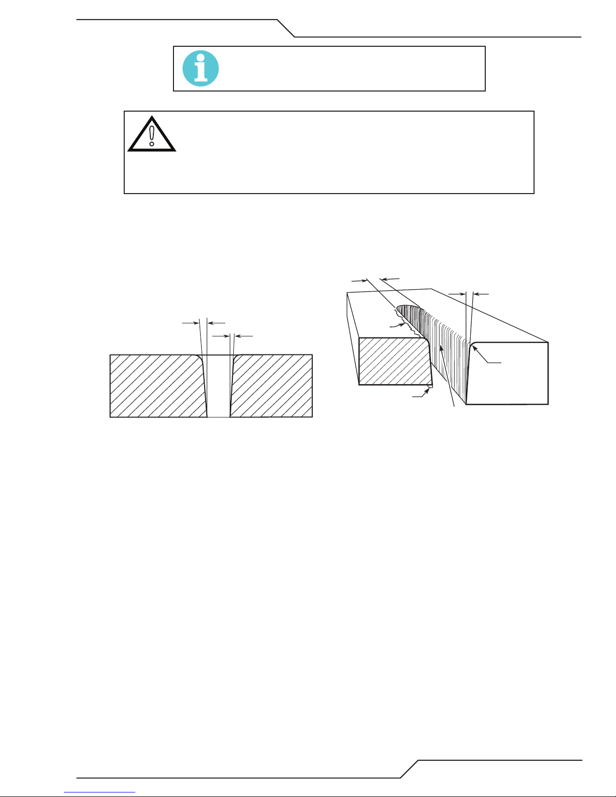
ULTRA-CUT 400 XT
Right Side
Cut Angle
Left Side
Cut Angle
A-00512
Kerf Width
Cut Surface
Bevel Angle
Top Edge
Rounding
Cut Surface
Drag Lines
Dross
Build-Up
Top
Spatter
A-00007
NOTE!
When switching gases between operations, allow enough
purge time to clear the prior gas from the torch leads.
CAUTION
!
Cut Quality
Cut quality requirements differ depending on application. For instance, nitride build-up and bevel angle may be major factors when
the surface will be welded after cutting. Dross-free cutting is important when finish cut quality is desired to avoid a secondary
cleaning operation. Cut quality will vary on different materials and thicknesses.
While nothing prevents the operator from switching gases during piloting or cutting
it is not recommended to do so. If the operator switches gases during piloting or
cutting, the power supply will finish the cut with the first gas chosen. Then the gas
control will switch to the new gas. Switching gases during piloting or cutting may
damage torch parts, torch leads, the control module, or the piece being cut.
Cut Surface
The condition (smooth or rough) of the face of the cut.
Bevel Angle
The angle between the surface of the cut edge and a plane perpendicular to the surface of the plate. A perfectly perpendicular
cut would result in a 0° bevel angle.
Top-Edge Rounding
Rounding on the top edge of a cut due to wearing from the initial contact of the plasma arc on the workpiece.
Dross Build-up and Top Spatter
Dross is molten material which is not blown out of the cut area and re-solidifies on the plate. Top spatter is dross which
accumulates on the top surface of the workpiece. Excessive dross may require secondary cleanup operations after cutting.
Kerf Width
The width of material removed during the cut.
Nitride Build-up
Nitride deposits which may remain on the cut edge of the carbon steel when nitrogen is present in the plasma gas stream.
Nitride buildups may create difficulties if the steel is welded after the cutting process.
Manual 0-5275 OPERATION 4-11
Page 78

ULTRA-CUT 400 XT
Right Side
Cut Angle
Left Side
Cut Angle
A-00512
Scrap
Clockwise
Counter-
Clockwise
Art # A-04182
Workpiece
Scrap
Direction of Cut
The plasma gas stream swirls as it leaves the torch to maintain a smooth column of gas. This swirl effect results in one
side of a cut being more square than the other. Viewed along the direction of travel, the right side of the cut is more square
than the left.
Swirl Effect on Side Characteristics Of Cut
To make a square - edged cut along an inside diameter of a circle, the torch should move counterclockwise around the circle.
To keep the square edge along an outside diameter cut, the torch should travel in a clockwise direction.
Underwater Cutting
Cutting on a water table either underwater or with the water touching the plate or with a water muffler system is not recommended. If a water table is used the water level must be a minimum of 4 inches from the bottom of the plate. Failure to follow
this recommendation could result in poor cut quality and short consumable parts life.
Ohmic Height Sensing
Ohmic height sensing is not recommended with water shield. Water on the plate interferes electrically with the ohmic sensing circuit.
4-12 OPERATION Manual 0-5275
Page 79

ULTRA-CUT 400 XT
4.07 Power Supply Status Codes
NOTE!
See the Appendix for Advanced Troubleshooting
On start-up and during operation, the power supply control circuitry performs various tests. If the circuitry detects a condition
requiring operator attention, the status display on the front panel shows a 3 digit number code preceded by either letter “E” (currently active fault) or letter “L” (last or latched fault) meaning a fault occurred stopping the process but is not currently active.
Some conditions can be active indefinitely, while others are momentary. The power supply latches momentary conditions; some
momentary conditions can shut down the system. The indicator may show multiple conditions in sequence; it is important to
recognize all possible conditions that may be displayed.
NOTE!
There are no Group 5 (500) numbered status codes with the GCM 2010 system.
These tables cover units up to 400A, Lower current units won’t have all the
inverter sections referred to in the Group 2. However codes for those sections
should not appear.
CCM Status Code
Code
101 Plasma Disabled
102 Pilot Ignition Failure
103 Lost Pilot
104 Transfer Lost
105 Not used Reserved for legacy product
106 Pilot Timeout, no Transfer
107 Tip Saver Fault Tip remained in contact with work in excess of 15 seconds. ( Pak200i).
Message
Remedy / Comments
Group 1 -- Plasma Process
Plasma Enable Off ; Disable activated on GCM 2010 or external SW disabled
(CNC); CCM TB1-1&2 jumper missing; 40 circuit ribbon cable from Relay
PCB to CCM disconnected or defective;
Pilot did not start within 15 seconds. Torch consumable parts worn? Ensure
correct process selected or manual setting including current control setting
matches consumables; Plasma pressure too high; Defective Arc Starter;
Defective Pilot PCB; defective Inverter section 1A. Ribbon cables reversed on
INV1 sections 1A and 1B.
Pilot went out while Start active. Torch consumable parts worn? Ensure cut
process or current control setting setting matches consumables; Plasma
pressure too high;
Arc was transferred to work then went out while Start still active. Arc lost
contact with work (run off edge, over hole, etc.); Standoff too high; Ensure
cut process or manual settings (current control, gas pressures) matches
consumables;
Must transfer from Pilot to Cutting Arc in 0.085 seconds (SW8-1 OFF) or 3
sec. (SW8-1 ON). Standoff too high or void in work under torch; Wrong cut
process selected or wrong manual settings (current control set too low or
wrong gas pressure).
108 Tip to Electrode voltage fault.
109 Part process not configured.
110 Devise Locked DFC 3000: Process loading; wait until finished
Manual 0-5275 OPERATION 4-13
Tip voltage too close to electrode voltage; Torch consumable parts worn out;
Wrong consumables installed causing tip to electrode short; Wrong process
selected or wrong manual setting of plasma gas or cutting current.; Leak in
Plasma hose to torch; Defective Pilot PCB; Shorted torch body .
Applies only to DFC 3000 Auto Gas Control. Select and load a cutting process.
Page 80

ULTRA-CUT 400 XT
CCM Status Code
Code Message Remedy / Comments
Group 2 -- Plasma Power Supply
201 Missing AC Phase
202 Not used Reserved for legacy product
203 Not used Reserved for legacy product
204 Not used Reserved for legacy product
205 DC Output Low
206 Not used Reserved for legacy product
207
208
209 Not used Reserved for legacy product
210
211 Work Current Too Low
Unexpected current in
work lead
Unexpected current in
pilot circuit
Work Current Too
High
Blown wall fuse, Blown unit fuse F1 or F2 or rear panel, Bad power cable connection;
Defective System Bias PCB.
Less than 60 VDC; Negative lead short to work or ground; Defective inverter (output shorted); CCM voltage sense (J24) disconnected or wire broken; Defective CCM.
Current above 8A in work lead prior to pilot ignition or transfer. Negative lead short
to ground or arcstarter chassis; Defective HCT1 work lead current sensor; Defective Relay PCB.
Current above 6A in pilot circuit prior to ignition. Wrong or mismatched consumables causing tip - electrode short; Pilot lead shorted to negative in torch tube;
Defective Relay PCB; Defective Pilot PCB; Possible shorted torch.
Work lead current detected greater than 16% above process setting. Possible defective HCT1 Work lead current sensor or Relay PCB; Defective CCM.
Work current detected more than 16% below process setting. Possible defective HCT1 Work lead current sensor or Relay PCB; Possible defective pilot PCB
(shorted IGBT);
212
213
214
215
216
217
218
219
220
221
Inverter 1A Output
Current Low
Inverter 1B Output
Current Low
Inverter 2A Output
Current Low
Inverter 2B Output
Current Low
Inverter 3A Output
Current Low
Inverter 3B Output
Current Low
Inverter 1A Output
Current High
Inverter 1B Output
Current High
Inverter 2A Output
Current High
Inverter 2B Output
Current High
Plasma work current low during cutting and attributed to Inverter Module 1 Section A output low; Inverter output disconnected; Possible defective ribbon cable; If
problem persists replace Inverter Module 1
Plasma work current low during cutting and attributed to Inverter Module 1 Section B output low; Inverter output disconnected; Possible defective ribbon cable; If
problem persists replace Inverter Module 1
Plasma work current low during cutting and attributed to Inverter Module 2 Section
A output low; Inverter output disconnected; Possible defective ribbon cable; If
problem persists replace Inverter Module 2
Plasma work current low during cutting and attributed to Inverter Module 2 Section
B output low; Inverter output disconnected; Possible defective ribbon cable; If
problem persists replace Inverter Module 2
Plasma work current low during cutting and attributed to Inverter Module 3 Section
A output low; Inverter output disconnected; Possible defective ribbon cable; If
problem persists replace Inverter Module 3
Plasma work current low during cutting and attributed to Inverter Module 3 Section
B output low; Inverter output disconnected; Possible defective ribbon cable; If
problem persists replace Inverter Module 2
Plasma work current high during cutting and attributed to Inverter Module 1 Section
A output high; If problem persists replace Inverter Module 1
Plasma work current high during cutting and attributed to Inverter Module 1 Section
B output high; If problem persists replace Inverter Module 1
Plasma work current high during cutting and attributed to Inverter Module 2 Section
A output high; If problem persists replace Inverter Module 2
Plasma work current high during cutting and attributed to Inverter Module 2 Section
B output high; If problem persists replace Inverter Module 2
4-14 OPERATION Manual 0-5275
Page 81

ULTRA-CUT 400 XT
CCM Status Code
Code Message
222
223
224 Inverter 1 Not Found
225
226
227
228
229
230
Inverter 3A Output
Current High
Inverter 3B Output
Current High
Inverter 1A Incompatible Revision
Inverter 1B Incompatible Revision
Inverter 2A Incompatible Revision
Inverter 2B Incompatible Revision
Inverter 3A Incompatible Revision
Inverter 3B Incompatible Revision
Plasma work current high during cutting and attributed to Inverter Module 3 Section
A output high; If problem persists replace Inverter Module 3
Plasma work current high during cutting and attributed to Inverter Module 3 Section
B output high; If problem persists replace Inverter Module 3
Inverter Module 1 Section A required for Piloting; Bad ribbon cable connection to
CCM J31 to Inverter Module 1 Section A.
Unsupported Inverter Revision; Ribbon cable CCM J31 to Inverter Module 1 Section
A damaged; CCM code version incompatible with Inverter revision or model
Unsupported Inverter Revision; Ribbon cable CCM J32 to Inverter Module 1 Section
B damaged ; CCM code version incompatible with Inverter revision or model
Unsupported Inverter Revision; Ribbon cable CCM J33 to Inverter Module 2 Section
A damaged; CCM code version incompatible with Inverter revision or model
Unsupported Inverter Revision; Ribbon cable CCM J34 to Inverter Module 2 Section
B damaged; CCM code version incompatible with Inverter revision or model
Unsupported Inverter Revision; Ribbon cable CCM J35 to Inverter Module 3 Section
A damaged; CCM code version incompatible with Inverter revision or model
Unsupported Inverter Revision; Ribbon cable CCM J36 to Inverter Module 3 Section
B damaged; CCM code version incompatible with Inverter revision or model
Remedy / Comments
231
232
233
234
235
236
237
238 BIAS VAC Invalid
239 AC Voltage High
240 AC Voltage Low
Inverter 1A VAC
Mismatch
Inverter 1B VAC
Mismatch
Inverter 2A VAC
Mismatch
Inverter 2B VAC
Mismatch
Inverter 3A VAC
Mismatch
Inverter 3B VAC
Mismatch
Too Few Inverters
Found
Inverter AC Voltage rating incompatible with Power Supply voltage rating; Bad
ribbon cable connection CCM J31 to Inverter Module 1 Section A; Wrong voltage
Inverter Module 1 installed; Defective Inverter module
Inverter AC Voltage rating incompatible with Power Supply voltage rating; Bad
ribbon cable connection CCM J32 to Inverter Module 1 Section B; Wrong voltage
Inverter Module 1 installed; Defective Inverter module
Inverter AC Voltage rating incompatible with Power Supply voltage rating; Bad
ribbon cable connection CCM J33 to Inverter Module 2 Section A; Wrong voltage
Inverter Module 2 installed; Defective Inverter module
Inverter AC Voltage rating incompatible with Power Supply voltage rating; Bad
ribbon cable connection CCM J34 to Inverter Module 2 Section B; Wrong voltage
Inverter Module 2 installed; Defective Inverter module
Inverter AC Voltage rating incompatible with Power Supply voltage rating; Bad
ribbon cable connection CCM J35 to Inverter Module 3 Section A; Wrong voltage
Inverter Module 3 installed; Defective Inverter module
Inverter AC Voltage rating incompatible with Power Supply voltage rating; Bad
ribbon cable connection CCM J36 to Inverter Module 3 Section B; Wrong voltage
Inverter Module 3 installed; Defective Inverter module
Two or more Inverter Sections required to operate; Ribbon cable from CCM to
Inverter Section damaged or disconnected;
Invalid AC Voltage Selection; Damaged or loose connection at J61 of System Bias
Supply; Defective System Bias PCB
System Bias PCB detected AC Voltage is higher than Power Supply rated Voltage;
System Bias Supply J61 Voltage Selection connection damaged or disconnected;
Defective System Bias PCB; Defective CCM
System Bias PCB detected AC Voltage is lower than Power Supply rated Voltage;
System Bias Supply J61 Voltage Selection connection damaged or disconnected;
Defective System Bias PCB; Defective CCM
Manual 0-5275 OPERATION 4-15
Page 82

ULTRA-CUT 400 XT
CCM Status Code
Code Message
Inverter Input Voltage fault; voltage out of range or missing phase at AC Input of In-
241
242
243
Inverter 1A Input Voltage Error
Inverter 1B Input Voltage Error
Inverter 2A Input Voltage Error
verter Module 1 Section A; Poor AC Power Quality; Defective W1 contactor; Loose or
open connection between input terminals and W1 contactor or contactor and input
of Inverter Section; Defective Inverter module
Inverter Input Voltage fault; voltage out of range or missing phase at AC Input of Inverter Module 1 Section B; Poor AC Power Quality; Defective W1 contactor; Loose or
open connection between input terminals and W1 contactor or contactor and input
of Inverter Section; Defective Inverter module
Inverter Input Voltage fault; voltage out of range or missing phase at AC Input of Inverter Module 2 Section A; Poor AC Power Quality; Defective W1 contactor; Loose or
open connection between input terminals and W1 contactor or contactor and input
of Inverter Section; Defective Inverter module
Remedy / Comments
244
245
246
247
248
249
250
251
252
253 Inverter 1A Over Temp
254 Inverter 1B Over Temp
Inverter 2B Input Voltage Error
Inverter 3A Input Voltage Error
Inverter 3B Input Voltage Error
Inverter 1A Circuit
Fault Inverter Module 1 Section A detected a circuit fault; Damaged Inverter Module 1
Inverter 1B Circuit
Fault Inverter Module 1 Section B detected a circuit fault; Damaged Inverter Module 1
Inverter 2A Circuit
Fault Inverter Module 2 Section A detected a circuit fault; Damaged Inverter Module 2
Inverter 2B Circuit
Fault Inverter Module 2 Section B detected a circuit fault; Damaged Inverter Module 2
Inverter 3A Circuit
Fault Inverter Module 3 Section A detected a circuit fault; Damaged Inverter Module 3
Inverter 3B Circuit
Fault Inverter Module 3 Section B detected a circuit fault; Damaged Inverter Module 3
Inverter Input Voltage fault; voltage out of range or missing phase at AC Input of Inverter Module 2 Section B; Poor AC Power Quality; Defective W2 contactor; Loose or
open connection between input terminals and W2 contactor or contactor and input
of Inverter Section; Defective Inverter module
Inverter Input Voltage fault; voltage out of range or missing phase at AC Input of Inverter Module 3 Section A; Poor AC Power Quality; Defective W2 contactor; Loose or
open connection between input terminals and W2 contactor or contactor and input
of Inverter Section; Defective Inverter module
Inverter Input Voltage fault; voltage out of range or missing phase at AC Input of Inverter Module 3 Section B; Poor AC Power Quality; Defective W2 contactor; Loose or
open connection between input terminals and W2 contactor or contactor and input
of Inverter Section; Defective Inverter module
Inverter Module 1 Section A is over temperature; Operating with side panels removed, Check for restricted air flow, clogged radiator; Defective fan; If problem
persists replace inverter module.
Inverter Module 1 Section B is over temperature; Operating with side panels removed, Check for restricted air flow, clogged radiator; Defective fan; If problem
persists replace inverter module.
Inverter Module 2 Section A is over temperature; Operating with side panels re-
255 Inverter 2A Over Temp
256 Inverter 2B Over Temp
4-16 OPERATION Manual 0-5275
moved, Check for restricted air flow, clogged radiator; Defective fan; If problem
persists replace inverter module.
Inverter Module 2 Section B is over temperature; Operating with side panels removed, Check for restricted air flow, clogged radiator; Defective fan; If problem
persists replace inverter module.
Page 83

ULTRA-CUT 400 XT
CCM Status Code
Code Message
257 Inverter 3A Over Temp
258 Inverter 3B Over Temp
259
260
261
262
263
264
265
266
267
268
269
270
271
Inverter 1A Over Temp
Ambient
Inverter 1B Over Temp
Ambient
Inverter 2A Over Temp
Ambient
Inverter 2B Over Temp
Ambient
Inverter 3A Over Temp
Ambient
Inverter 3B Over Temp
Ambient
Inverter 1A No Input
Power
Inverter 1B No Input
Power
Inverter 2A No Input
Power
Inverter 2B No Input
Power
Inverter 3A No Input
Power
Inverter 3B No Input
Power
Inverter ID reading
fault
Inverter Module 3 Section A is over temperature; Operating with side panels removed, Check for restricted air flow, clogged radiator; Defective fan; If problem
persists replace inverter module.
Inverter Module 3 Section B is over temperature; Operating with side panels removed, Check for restricted air flow, clogged radiator; Defective fan; If problem
persists replace inverter module.
Inverter circuitry is over temperature likely cause is ambient greater than 40 deg
C; Reduce power supply cutting Duty Cycle; Reduce ambient air temperature; Add
auxiliary cooler.
Inverter circuitry is over temperature likely cause is ambient greater than 40 deg
C; Reduce power supply cutting Duty Cycle; Reduce ambient air temperature; Add
auxiliary cooler.
Inverter circuitry is over temperature likely cause is ambient greater than 40 deg
C; Reduce power supply cutting Duty Cycle; Reduce ambient air temperature; Add
auxiliary cooler.
Inverter circuitry is over temperature likely cause is ambient greater than 40 deg
C; Reduce power supply cutting Duty Cycle; Reduce ambient air temperature; Add
auxiliary cooler.
Inverter circuitry is over temperature likely cause is ambient greater than 40 deg
C; Reduce power supply cutting Duty Cycle; Reduce ambient air temperature; Add
auxiliary cooler.
Inverter circuitry is over temperature likely cause is ambient greater than 40 deg
C; Reduce power supply cutting Duty Cycle; Reduce ambient air temperature; Add
auxiliary cooler.
Inverter section may have no input power. Contactor W1 not closed; Defective contactor or CB4 tripped; Inverter section input not connected; Defective Inverter.
Inverter section may have no input power. Contactor W1 not closed; Defective contactor or CB4 tripped; Inverter section input not connected; Defective Inverter.
Inverter section may have no input power. Contactor W1 not closed; Defective contactor or CB4 tripped; Inverter section input not connected; Defective Inverter.
Inverter section may have no input power. Contactor W2 not closed; Defective contactor or CB4 tripped; Inverter section input not connected; Defective Inverter.
Inverter section may have no input power. Contactor W2 not closed; Defective contactor or CB4 tripped; Inverter section input not connected; Defective Inverter.
Inverter section may have no input power. Contactor W2 not closed; Defective contactor or CB4 tripped; Inverter section input not connected; Defective Inverter.
CCM found ID values inconsistant during reading. CCM to an Inverter section ribbon damaged or disconnected; Inproper ribbon cable routing.
Remedy / Comments
Manual 0-5275 OPERATION 4-17
Page 84

ULTRA-CUT 400 XT
CCM Status Code
Code Message Remedy / Comments
Group 3 -- Gas Controller Status & Protocol
301
302 Gas Control reply fault
303
304 Gas Control Purging Normal following power up or returning from Plasma Disable. Wait for purge to finish.
305 Gas Control protocol error
306 Not used Reserved for other future use.
307 Gas Control sequencing error Verify Firmware revision for compatibility with GCM 2010
308 Gas Control Type Mismatch Wrong CCM (Auto-Cut or Pak 200 type?) for Ultra-Cut; Install correct CCM
309 Gas Control command fault
310 * DPC fault Check DPC status indicator for specific problem
311 * DPC valve control fault Check DPC status indicator for specific problem
312 * DMC fault Check DMC status indicator for specific problem
313 * Gas Controller not configured. DMC or DPC not configured for a process or locked; See DMC and DPC status
* Applies to DFC 3000 (Auto Gas) only
Gas control communication
fault
Gas Supply Pressure out of
range.
Problem with fiber optic cable to GCM 2010; Dirt on fiber ends or in connectors; blow
out with clean dry air. Fiber not locked into connector; Sharp bends in fiber cable;
Fiber defective; GCM 2010 circuit board defect;
Problem with fiber optic cable to GCM 2010; Dirt on fiber ends or in connectors; blow
out with clean dry air. Fiber not locked into connector; Sharp bends in fiber cable;
Fiber defective; GCM 2010 circuit board defect;
GCM 2010 inlet plasma or shield pressure low or defective pressure sensors PS3 &
PS4; Defective GCM 2010 PCB.
Verify Firmware revision for compatibility with GCM 2010
Verify Firmware revision for compatibility with GCM 2010; Electromagnetic interference with Arc Starter; inspect grounding; bonding; and isolation
CCM Status Code
Code Message Remedy / Comments
Group 4 -- Torch Coolant System
401
402
403
404
405
406
Coolant Level
low
Low coolant
flow
Coolant overheated
Coolant System
not ready.
Low Coolant
Level Warning
Coolant Flow
Low Warning.
Check coolant level, add as needed. Defective or disconnected level sensor.
Coolant flow as measured by flow switch FS1 is less than 0.7 gpm (0.25 for Pak200i); Clogged
filter; Restriction in torch lead or head; Wrong style consumables; Bad O-ring on the torch check
valve; broken or defective torch coolant tube/check valve; Defective pump or bypass valve. 402
code along with 104 code is probably a low flow problem.
Coolant supply temperature exceeded 75 degrees Celcius (167F). Operating with side panel
loose or removed; Air flow blocked at air inlet or exit of power supply; Coolant fan failed; radiator
fins clogged with dirt.
Proper coolant flow of 0.7 gpm as measured by flow switch FS1 was not obtained during up to
4 minutes of Priming. New installation can require additional Priming cycle(s) to fill hoses with
coolant; cylce power to restart Priming; Coolant hoses or torch hoses reversed; Clogged coolant
filter; Restriction in torch lead or head; Wrong style consumables; broken or defective torch coolant tube/check valve; Defective or disconnected FS1 flow SW; Defective pump or bypass valve.
Low coolant level during cut, does not stop cut.
Add coolant as required.
This is a warning, does not stop system operation. Coolant flow rate lower than expected. Can be
caused by gas bubbles being introduced into the coolant or wrong or mismatched or worn consumable parts; Failed seals in torch cartridge or torch body; Clogged coolant filter; Restriction in torch
lead or head; defective or disconnected FL1 flow sensor.
Coolant over-
407
4-18 OPERATION Manual 0-5275
heated, high
ambient.
Coolant supply temperature exceeded 75 degrees Celsius (167 Fahrenheit) likely cause ambient
greater than 40 degrees Celsius (104 Fahrenheit); Reduce cutting duty cycle; Reduce ambient
temperature; Add separate coolant cooler.
Page 85

ULTRA-CUT 400 XT
No Group 5 (500) status codes with GCM 2010 system.
CCM Status Code
Code Message Remedy / Comments
Group 6 -- CCM
601 Analog Voltage Error Defective CCM, replace.
602 ADC or DAC error Defective CCM, replace.
603 Reserved No information available; Contact customer service
604 Data Memory error Defective CCM, replace.
605 Program memory fault Defective CCM, replace.
606 +5V Logic supply low Defective CCM, replace.
607 Processor over temperature Reduce ambient temperature; Defective CCM; replace
608
609 Firmware Update Device Error Defective CCM; replace
610 Firmware Update Protocol Error Defective CCM; replace
611 USB Controller Fault Defective CCM; replace
612
613
614
615
616
617
618 ADC Calibration Fault Error too large calibrating ADC; Fault persists defective CCM;
619 Flow Switch Fault Flow switch reporting coolant flow when pump off;
620
621 USB Format Fault
622 CCM Code Execution Fault
5V supply for RS 485/422 communication low.
USB Power Fault
USB Log Creation Fault
No USF File
No CCM Update File
DPC Update Fault
DMC Update Fault
Non Volatile Memory Error
Defective CCM, replace.
Faulty USB device plugged into USB port, remove; Defective CCM
Unable to create Log file on USB Flash drive last firmware update at-
tempt; Use different USB Flash Drive or Reformat
File VTCCMFW.USF missing from Flash Drive; Add proper files to Flash
Drive for Firmware Update; Use different USB Flash Drive or Reformat
CCM Firmware file specified in VTCCMFW.USF not found ; Add proper
files to Flash Drive for Firmware updating
Fault occurred attempting to update DPC firmware; Add proper files to
USB Flash drive for Firmware updating; Refer to CCM_LOG.TXT on Flash
Drive for details
Fault occurred attempting to update DMC firmware; Add proper files to
USB Flash drive for Firmware updating; Refer to CCM_LOG.TXT on Flash
Drive for details
Non Volatile Memory Storage Corrupted and Erased; Fault persists
defective CCM.
A USB flash drive was detected but could not be read by CCM. Backup
any files currently on flash drive, reformat the USB flash drive to a FAT or
FAT32 file system, replace only the CCM update files and try again. Use
different USB flash drive formatted with FAT or FAT32 file system.
Possible EMI noise problem or code fault. Check for proper grounding and bonding of equipment and routing of torch leads and cables
to reduce Electromagnetic Emission Interference onto CCM module. If
problem persists, verify CCM code version is the latest supported revision. Replace CCM module.
Manual 0-5275 OPERATION 4-19
Page 86

ULTRA-CUT 400 XT
CCM Status Code
Code Message Remedy / Comments
Group 7 -- Options
1 Torch isolation contactor W5 appears closed when expected to be
701 Isolation Contactor Fault
702 Contact Start consumable fault
703
704 Contact Start pressure fault
705 Contact Start Cartridge fault
Contact Start detection circuit
fault
open. Contacts may fused or, W5 could be energized, 24 VAC on it's
coil, when it should not be due to faulty Relay PCB.
Prior to 1 torch preflow there should be continuity from the electrode,
through the start cartridge, to the tip. Failure may be due to worn or
missing consumable or Start Cartridge. Inspect, clean or replace.
In the 1 Torch module K201 should energize when W5 does. Either it
failed to energize or the pressure switch PS2 is failed closed.
Pressure switch PS2 detects less than 35 PSI. Normal pressure is 75-85
PSI. No air connected to the 1 Torch module inlet or it's too low pressure; if using optional single stage filter the element may need cleaning
or replacement, refer to maintance section. ;1 Torch pressure regulator
set too low; 1 torch module solenoid SOL4 has failed; Relay PCB does
not apply 24 VAC to SOL4.
Air pressure should seperate the Start Cartridge from the tip to initiate
pilot. Failure may be stuck or damaged cartridge or consumables. Clean
or replace. Or no DC output from inverters, front panel DC LED does not
come on.
4-20 OPERATION Manual 0-5275
Page 87

ULTRA-CUT 400 XT
4.08 Remote Arc Starter Trouble Shooting
Arc Starter Trouble Shooting
Symptom Cause Check Remedy
Pilot return wire not connected
No Pilot ignition
Neon indicator on
Cap board lights
but no ignition.
No Pilot ignition:
Neon indicator
not illuminated.
Coolant Leaks
No cooling or
insuf¬ficient cool-
ing: No Coolant
Flow
Erratic System
Behavior(EMI
Interference
at torch head or broken in torch
lead
Coolant has become conductive Use conductivity meter
High Frequency cap (C4 on
Cap PCB) possibly open wires
disconnected.
Negative supply cable not connected correctly
Pilot return wire not connected
or loose in arcstarter.
No 120V supply, CB4 of plasma
rear panel tripped
Electronic Ignition module
shorted input
No 120V supply, CB4 not
tripped
Faulty Electronic Ignition
module
Loose fitting(s) Visual inspection Tighten fittings.
Damaged or punctured coolant
line(s).
Supply & return hose reversed
Blockage in supply/return hoses
Missing or loose
ground connection
Torch Lead Shield not connected
or loose. F1 gnd cable not connected.
Cap board ground screw not
tight or missing.
Cap C5 or C7 (on Cap PCB) open
or disconnected wires to Cap
board.
Visual inspection, continuity check Connect Wire or replace leads.
Flush system,
replace coolant.
Use capacitance meter Reconnect or replace.
Visual inspection Reconnect
Visual inspection Connect Wire.
Reset breaker, check for 120 VAC
at the module’s 115V terminals
during ignition time.
Resistance measurement, good
module measures about 45 ohms
check for 120 VAC at the plasma
supply’s rear panel connector J597 & 9 during ignition time.
Check for 120 VAC at the modules
115V terminals during pilot ignition time
Visual inspection Replace Coolant Lines
Visual Inspection of color-coded
connections
Loosen fitting slightly and check
for coolant flow
Visual inspection of ground wire
to Arc Starter
Visual inspection of lead shield
attachment to Arc Starter
Visual inspection Tighten or replace.
Visual inspection / capacitor
measurement
Check for shorted cable, defective circuit breaker, shorted
ignition module input. (see
next symptom)
Replace bad module
120V present - open control
cable, 120V not present - fault
in plasma power supply
If 120 VAC is present but neon
not illuminated, module is
defective, replace module
Match coolant connection
colors
to arc starter fitting colors.
Flush system or replace
blocked hose.
Make or tighten connections to
good ground.
Reconnect / tighten lead connectors.
Replace PCB.
Manual 0-5275 OPERATION 4-21
Page 88

ULTRA-CUT 400 XT
This Page Intentionally Blank
4-22 OPERATION Manual 0-5275
Page 89

ULTRA-CUT 400 XT
SECTION 5: MAINTENANCE
5.01 General Maintenance
Perform the following checks periodically to ensure proper system performance.
Power Supply Maintenance Schedule
Daily
Check coolant level; add coolant as needed.
Check gas hose connections and pressures.
Check cooling fan; clean as needed.
Weekly
Check O-Rings in Torch and Cartridge
Monthly
Check cooling fan and radiator; clean as needed.
Check gas hoses for cracks, leaks, or abrasion.
Replace as needed.
Check all electrical connections for cracks or
abrasion. Replace as needed.
Clean water lter (if using H2O Mist)
Six Months
Clean or replace coolant lter.
Clean coolant tank.
Vacuum out any dust buildup inside power supply.
5.02 External Coolant Filter Cleaning Procedure
Periodic cleaning of the coolant filter ensures maximum coolant flow efficiency. Poor coolant flow causes inefficient torch parts
cooling with consequent faster consumable wear.
Clean the coolant filter as follows:
1. Disconnect system from main input power.
2. Unscrew and remove the filter canister by hand. Large canister located at the back of the power supply. Be sure to keep
the O-ring.
3. Inspect and replace filter as needed. Re-install the canister, tightening it by hand. Be sure the O-ring is in place.
4. Turn the system on and check for leaks.
Manual 0-5275 MAINTENANCE 5-1
Page 90

ULTRA-CUT 400 XT
5.03 Coolant Replacement Procedure
Replace coolant as follows:
1. Disconnect the system from main input power.
2. Remove the two right side panels.
3. Locate the coupling in the coolant line that comes from the bottom of the coolant tank, #1 in the following illustration.
Disconnect the coolant line at this fitting and drain the coolant into a disposable container of sufficient size. Remember
you will be draining more than the contents of the coolant reservoir.
4. Once coolant is draining, disconnect the gray hose coupling #2 in the illustration below. Allow excess coolant to drain,
then apply a maximum of 5psi to clear the lines.
CAUTION
!
Applying more than 5 psi air pressure to the cooling system will result in damage.
Extra caution must be used when performing this task.
2
1
Art # A11689
5. Reconnect those two fittings and then remove the filter bowl from the canister at the rear of the power supply. Pour this
remaining coolant into the container and replace the filter bowl.
NOTE!
If you also need to replace the coolant still in the leads, disconnect the leads
from the power supply and manually drain them.
6. Fill the tank with fresh coolant until the right level is reached checking for leaks.
7. Turn system on, let it run for a few minutes and check coolant level, refill as needed. Refer to Section 3:22 Complet the
Installation on the procedure for this.
8. Install the side panels.
5-2 MAINTENANCE Manual 0-5275
Page 91

ULTRA-CUT 400 XT
SECTION 6: REPLACEMENT ASSEMBLIES & PARTS
6.01 Replacement Power Supply
Complete Unit / Component Catalog Number
Ultra-Cut 400 XT™ Power Supply, 480V +10 -15% 3-8120-2
Ultra-Cut 400 XT™ Power Supply, 480V +10 -15% with SL100 interface 3-8120-2T
Gas Control Module (GCM-2010) with XTL Torch Valve Assembly 3-9131
Gas Control Module (GCM-2010) Only 7-4000
Original Torch Valve Assembly Repair Part Only 4-3049
XTL Torch Valve Assembly Only 4-3054
(Requires GCM 2010 Firmware version 3.1 or higher)
Remote Arc Starter (RAS-1000 XT) 3-9130E
OPTIONAL EQUIPMENT:
Wheel Kit 9-7378
Manual 0-5275 REPLACEMENT PARTS 6-1
Page 92

ULTRA-CUT 400 XT
6.02 System Layout
Refer to section 3.05 for ground connections and ground cables.
175’ / 53.3 m Maximum Length
F1
Primary power
CNC
Art # A-11940
P
Pilot Return #8
Coolant Supply 10’
Coolant Return 10’
Control Cable
Ultra-Cut
XT Power
Supply
Fiber
Optic
Cable
Control
Cable
125’ / 38.1 m Maximum Length
Negative Cable
Control Cable
C
HE 400
D
Heat
Exchanger
Y
L
Gas Control
Module
K
F
Coolant Supply
Coolant Return
Plasma Gas
Shield Gas
Preflow Gas
Control
Cable
Water
Shield
A
B
E
F1
H
Q
R
S
T
Remote
C
D
Torch
Valve
Assembly
Work Cable
50’ / 15.25 m Maximum Length
Pilot Return
Arc
Starter
Coolant Supply
Coolant Return
Plasma Gas
Shield Gas
Shield
Shield
Positioning Tube
I
G
J
Torch
Work
175’ / 53.3 m Maximum Length
6.03 Recommended Gas Supply Hose
Item # Qty Description Catalog #
1 3/8”Gray Synflex Hose. No fittings included. Catalog number per foot 9-3616
6-2 REPLACEMENT PARTS Manual 0-5275
Page 93

ULTRA-CUT 400 XT
6.04 Leads And Cables All Amperages
#8 AWG Cable
A
Pilot Return, Power Supply
to Arc Starter
Art # A-11873_AB
B
C
D
E,Y
14/7
F
F1
G
I
Green
Red
3/0 AWG Cable (95 mm
Green / Yellow # 4 AWG
Green / Yellow 1/0 (50 mm )
2
)
Green
Red
2
Negative Lead, Power Supply
to Arc Starter
Coolant Supply Lead,
Power Supply to Arc Starter
Coolant Return Lead,
Power Supply to Arc Starter
E - Control Cable, Power Supply
to Arc Starter
Y - Control Cable to Heat Exchanger
Ground Cable
Ground Cable,
Remote Arc Starter
To Earth Ground
Shielded Torch Lead
Assembly, Remote
Arc Starter to Torch
Plasma Gas Lead,
Torch Valve to Torch
J
K
L
H, Q,
R, S,T
O
P
37
37
3/0 (95 mm ) Cable
2
Shield Gas Lead,
Torch Valve to Torch
Control Cable,
Power Supply to
Gas Control Module
Fiber Optic Cable,
Power Supply to
Gas Control Module
Work Cable
CNC Cable (37 Wire)
Manual 0-5275 REPLACEMENT PARTS 6-3
Page 94

ULTRA-CUT 400 XT
H,Q,R,S,T Gas Lead Set (Note 2) 4-3035 4-3036 4-3037 4-3051 4-3038 4-3039 4-3040 4-3041 4-3042 4-3043
Q Shield Gas Hose 9-7277 9-7278 9-7279 9-7280 9-7281 9-7282 9-7283 9-7284 9-7285 9-7286
H Plasma Gas Hose 9-7103 9-7104 8-0149 9-7270 9-7271 9-7272 9-7273 9-7274 9-7275 9-7276
R Pilot Gas/Pre-Flow Hose 9-6956 9-6957 9-6958 9-6959 9-6960 9-6961 9-6962 9-6963 9-6964 9-7080 9-7081 9-4876 9-4877
S Control Cable 9-4878 9-4753 9-4755 9-4756 9-4757 9-4758 9-4759 9-4760 9-4761 9-4879 9-4880 9-4881
T Water Shield 9-6985 9-6986 9-6988 9-6996 9-6992 9-6993 9-7073 9-7074 9-7075 9-7076
NOTE 1: Supply lead sets inslude Pilot Return Cable, Negative Cable, Coolant Supply & Return Hoses and Control Cable.
NOTE 2: Gas lead sets include Plasma Gas Hose, Shield Gas Hose and Preow Gas Hose not combined.
O Work Cable 9-7350 9-7351 9-7352 9-7353
P
Control Cable, CNC to
PS
K
L Control Cable Fiber Optic 9-4898 9-4899 9-4900 9-9335 9-4901 9-4902 9-4903 9-4904 9-4905 9-4906
Control Cable, PS to
GCM
J Shield Lead 9-3334
I Plasma Lead 9-3333
F1
G Assembly, Torch Lead 4-5200 4-5201 4-5202 4-5203 4-5204 4-5205 4-5206 4-5207 4-3016
to Earth
Ground Wire, Remote AS
F Ground Wire, PS to GCM 9-4923 9-4924 9-4925 9-4926 9-4927 9-4928 9-4929 9-4930
Starter
E
Control Cable to Arc
C Hose, Coolant Supply 9-4805 9-4887 9-4806 9-4807 9-9424 9-4808 4-3202 9-4809 9-4810 9-4812
D Hose, Coolant Return 9-4813 9-4889 9-4814 9-4815 9-9425 9-4816 4-3203 9-4817 9-4818 9-4820
B Negative Cable 9-7356 9-7357 9-7358 9-7359 9-7360 9-7361 4-3201 9-7362 9-7363 9-7364
A Pilot Return Cable 9-4890 9-4891 9-4790 9-4791 9-9426 9-4792 4-3200 9-4793 9-4794 9-4796
A,B,C,D,E Supply Lead Set (Note 1) 4-3096 4-3097 4-3098 4-3099 4-3100 4-3101 4-3105 4-3102 4-3103 4-3104
Key Description
9-7368 9-7369 9-7370 9-7371 9-7372
9-4907 9-4908 9-4909 9-9332 9-4910 9-4911 9-4912 9-4913 9-4914
9-4931 9-4932 9-4933 9-4934 9-4935 9-4936 9-4937 9-4938
9-4941 9-4916 9-4917 9-4918 9-9428 9-4942 4-3205 9-4943 9-4944 9-4922
1.2 m
4 ft
3.05 m
10 ft
4.5 m
15 ft
20 ft
6 m
7.6 m
25 ft
9.1 m
30 ft
10.6 m
35 ft
12 m
40 ft
15.2 m
50 ft
Ultra-Cut XT Leads
18.3 m
60 ft
22.8 m
75 ft
30.5 m
100 ft
38.1 m
125 ft
45.7 m
150 ft
53.3 m
175 ft
6-4 REPLACEMENT PARTS Manual 0-5275
Page 95

ULTRA-CUT 400 XT
6.05 Power Supply External Replacement Parts
Item # Qty Description Catalog #
1 1 Power and Leads Cable Cover 9-7346
2 1 Top Panel, 9-7300
3 1 Upper Side Covers 9-7301
4 1 Lower Left Side Panel 9-7304
5 1 Lower Right Side Panel (300A/400A) 9-7344
6 1 Lifting Eye 9-9373
Art # A-11968
1
2
3 3
4
1
6
5
Manual 0-5275 REPLACEMENT PARTS 6-5
Page 96

ULTRA-CUT 400 XT
6.06 Power Supply Replacement Parts - Upper Right Side
Item # Qty Description Ref. Des. Catalog #
1 1 System Bias PCB 9-9253
2 1 Pilot PCB 9-9250
3 1 CCM Assembly 9-7335
4 1 Relays, Pump / Fan MC3 / MC2 9-7314
5 1 Relay, Inrush Control K1 9-7336
6 1 Relay, Inrush MC1 9-7337
7 1 Resistor, Inrush R2 9-7376
8 1 Display PCB 9-9252
9 1 Auxiliary Transformer T1 9-7315
10 1 On/Off Switch Breaker CB1 9-7316
11 1 Relay and Interface PCB 9-9251
11
10
1
9
8
7
6
5
4
2
3
6-6 REPLACEMENT PARTS Manual 0-5275
Art # A-11546_AB
Page 97

ULTRA-CUT 400 XT
2
3
4
5
6
7
1
Art # A-11984_AB
8
6.07 Power Supply Replacement Parts - Lower Right Side
Item # Qty Description Ref. Des. Catalog #
1 1 Coolant Tank, Cap 8-5124
2 1 Coolant Tank 9-7306
3 1 Sensor, Coolant level 9-7307
4 1 Pump, Coolant, Assembly (with motor) 9-7309
1 Pump, Coolant, Assembly (no motor) 9-7422
5 1 Motor, Pump (motor only) 9-7424
6 1 Heat Exchanger Fan 9-7348
7 1 Radiator 9-7349
8 1 Flow, Switch (Not shown) FS1 9-7310
9 1 Bubble (flow) Sensor (Not shown) FL1 9-9297
10 1 Current Transducer, 300A (Not shown) HCT1 W7005324
Manual 0-5275 REPLACEMENT PARTS 6-7
Page 98

ULTRA-CUT 400 XT
6.08 Power Supply Replacement Parts - Rear Panel
Item # Qty Description Breaker Rating Circuit Rating Ref. Des. Catalog #
1 1 Coolant Filter Assy 9-7320
2 1 Coolant Filter 9-7321
3 1 Fuse, 8A SB 500 VAC 9-7377
1
J55 - GCM
J15 - CNC
USER INPUT
HEIGHT CONTROL
2
J54 - TSC /COMM
J59 - RAS
J70 - HE
F1 - 8A SB 500 VAC F2 - 8A SB 500 VAC
CB2 - 5A 120 VAC
CB3 - 5A 24 VAC
CB4 - 5A 120 VAC
3
Art # A-11549_AC
6-8 REPLACEMENT PARTS Manual 0-5275
Page 99

ULTRA-CUT 400 XT
6.09 Power Supply Replacement Parts - Left Side
Item # Qty Description Ref. Des. Catalog #
1 1 AC Suppresion PCB 9-9254
2 1 Main Contactor (2 total) W1, W2 9-7318
3 1 Inverter Module, Full 480 VAC (3 total) 9-7330
1
2
Art # A11990
3
Manual 0-5275 REPLACEMENT PARTS 6-9
Page 100

ULTRA-CUT 400 XT
Art # A-07030_AB
2
1
1
1
1
3
7
8
4
5
6
3
3
1
1
8
9
10
12
12
14
11
11
13
12
14
11
6.10 Gas Control Module (GCM-2010) Replacement Parts
Item # Qty Description Catalog #
1 6 7W Solenoid for O2 use 9-9393
2 1 Gas Selection Manifold Assembly 9-9391
3 1 Check Valve, 1/4 NPT .5 PSI 9-9390
4 1 Mode Switch Assembly 9-9406
5 1 Gas Selection Switch Assembly 9-9403
6 1 LCD Interface PC Board 9-9408
7 1 Rotary Encoder (Switch) 9-9398
8 1 Toggle Switch 9-3426
9 1 Solenoid / Logic PC Board 9-9409
10 1 Cover 9-9410
11 3 Gauge, 0-160 psi 8-6800
12 1 Regulator 8-3223
13 1 Pressure Transducer and wire harness 100 PSI 9-9407
14 2 Pressure Transducer and wire harness 250 PSI 9-9508
NOT SHOWN:
1 Torch Valve Assembly Wire Harness (J13 to J57) 9-9399
1 Power Supply Connection Wire Harness (J3 & J5 to J56) 9-9400
1 LCD Interface PC Board Wire Harness 9-9401
1 Rotary Encoder (Switch) Wire Harness 9-9402
1 Solenoid Drive A Wire Harness (J12 to Solenoids 1-6) 9-9404
1 Solenoid Drive B Wire Harness (J1 to Solenoids 7-12) 9-9405
6-10 REPLACEMENT PARTS Manual 0-5275
 Loading...