

Page 1

R
EUROPEAN
Air Plasma Cutting System
For 110VAC Systems
The System Includes:
• Pak Master
• EMC PCH-25 Torch with Leads
• Input Power Cable
• Work Cable with Clamp
®
25™ EMC Power Supply
October 31, 2002
Operating Manual
Manual No. 0-2577
Page 2

Page 3
WARNING
WARNING
Read and understand this entire Manual and your employer’s
safety practices before installing, operating, or servicing the
equipment.
While the information contained in this Manual represents our
best judgement, Thermal Dynamics Corporation assumes no
liability for its use.
Pak Master 25 EMC Air Plasma Cutting System(110VAC)
Operating Manual No. 0-2577
Published by
Thermal Dynamics Corporation
Industrial Park No. 2
West Lebanon, New Hampshire, USA 03784
(603) 298-5711
Copyright 1994 by
Thermal Dynamics Corporation
All rights reserved.
Reproduction of this work, in whole or in part, without written
permission of the publisher is prohibited.
The publisher does not assume and hereby disclaims any liabil-
ity to any party for any loss or damage caused by errors or
omissions in the Pak Master 25 EMC Air Plasma Cutting System
(110VAC) Operating Manual, whether such errors result from
negligence, accident, or any other cause.
Printed in the United States of America
October 31, 2002
Page 4

Record Serial Numbers For Warranty Purposes
Purchase Date
Power Supply
Torch
Page 5

TABLE OF CONTENTS
GENERAL INFORMA TION............................................................................................................. i
Notes, Cautions and W arnings ................................................................................. i
Important Safety Precautions .................................................................................. i
Publications .............................................................................................................ii
Note, Attention et Av ertissement ............................................................................iii
Precautions De Securite Importantes ..................................................................... iii
Documents De Reference ....................................................................................... v
Declaration of Conformity.......................................................................................vii
Statement of W arranty .......................................................................................... viii
SECTION 1: INTRODUCTION & DESCRIPTION ......................................................................... 1
1.1 SYSTEM DESCRIPTION ................................................................................ 1
1.2 SYSTEM OPTIONS AND T ORCH PARTS ........................................................ 2
SECTION 2: INSTALLATION ........................................................................................................3
2.1 UNP A CKING AND CHOOSING A LOCA TION ................................................... 3
2.2 ELECTRICAL CONNECTIONS ........................................................................ 4
2.3 GAS CONNECTIONS ...................................................................................... 5
SECTON 3: OPERA TION............................................................................................................. 7
3.1 OPERA TING CONTROLS................................................................................ 7
3.2 GETTING STARTED........................................................................................ 8
3.3 SEQUENCE OF OPERATION ......................................................................... 9
3.4 CUT QUALITY ................................................................................................10
3.5 OPERATING THE SYSTEM ...........................................................................12
3.6 OPERA TING WITH A HAND T ORCH................................................................14
3.7 RECOMMENDED CUTTING SPEEDS ...........................................................15
SECTION 4: CUST OMER/OPERATOR SERVICE .......................................................................17
4.1 POWER SUPPLY SPECIFICA TIONS .............................................................17
4.2 T ORCH SPECIFICATIONS .............................................................................18
4.3 REPLACEMENT TORCHES AND LEADS ......................................................19
4.4 BASIC TR OUBLESHOOTING GIUIDE AND MAINTENANCE ..........................20
4.5 REPLACING CONSUMABLE TORCH PARTS.................................................22
4.6 GENERAL T ORCH MAINTENANCE ...............................................................23
4.7 SERVICING TORCH HEAD COMPONENTS...................................................24
4.8 REPLACING TORCH AND LEADS .................................................................28
SECTION 5: PARTS LISTS.........................................................................................................31
5.1 REPLACEMENT COMPLETE ASSEMBLIES.................................................31
5.2 REPLACEMENT HAND TORCH PARTS .........................................................32
5.3 MISCELLANOUS PARTS ...............................................................................33
APPENDIX I: SYSTEM SCHEMATIC .........................................................................................34
Page 6

TABLE OF CONTENTS (continued)
Page 7
GENERAL INFORMATION
GASES AND FUMES
Notes, Cautions and Warnings
Throughout this manual, notes, cautions, and warnings
are used to highlight important information. These highlights are categorized as follows:
NOTE
An operation, procedure, or backgr ound information which requires additional emphasis or is helpful in efficient operation of the system.
CAUTION
A procedure which, if not properly followed, may
cause damage to the equipment.
WARNING
A procedure which, if not properly followed, may
cause injury to the operator or others in the operating area.
Important Safety Precautions
WARNINGS
OPERATION AND MAINTENANCE OF
PLASMA ARC EQUIPMENT CAN BE DANGEROUS AND HAZARDOUS TO YOUR
HEALTH.
Plasma arc cutting produces intense electric and
magnetic emissions that may interfere with the
proper function of cardiac pacemakers, hearing
aids, or other electronic health equipment. Persons who work near plasma arc cutting applications should consult their medical health professional and the manufacturer of the health equipment
to determine whether a hazard exists.
Gases and fumes produced during the plasma cutting
process can be dangerous and hazardous to your health.
• Keep all fumes and gases from the breathing area.
Keep your head out of the welding fume plume.
• Use an air-supplied respirator if ventilation is not
adequate to remove all fumes and gases.
• The kinds of fumes and gases from the plasma arc
depend on the kind of metal being used, coatings
on the metal, and the different processes. Y ou must
be very careful when cutting or welding any metals which may contain one or more of the following:
Antimony Chromium Mercury
Arsenic Cobalt Nickel
Barium Copper Selenium
Beryllium Lead Silver
Cadmium Manganese Vanadium
• Always read the Material Safety Data Sheets (MSDS)
that should be supplied with the material you are
using. These MSDSs will give you the information
regarding the kind and amount of fumes and gases
that may be dangerous to your health.
• For information on how to test for fumes and gases
in your workplace, refer to item 1 in Subsection
Publications, in this manual.
• Use special equipment, such as water or down draft
cutting tables, to capture fumes and gases.
• Do not use the plasma torch in an area where combustible or explosive gases or materials are located.
• Phosgene, a toxic gas, is generated from the vapors
of chlorinated solvents and cleansers. Remove all
sources of these vapors.
• This product, when used for welding or cutting,
produces fumes or gases which contain chemicals
known to the State of California to cause birth defects and, in some cases, cancer . (California Health
& Safety Code Sec. 25249.5 et seq.)
ELECTRIC SHOCK
To prevent possible injury, read, understand and
follow all warnings, safety precautions and instructions before using the equipment. Call 1-603298-5711 or your local distributor if you have any
questions.
Date: November 15, 2001 (Special) i GENERAL INFORMA TION
Electric Shock can injure or kill. The plasma arc process
uses and produces high voltage electrical energy. This
electric energy can cause severe or fatal shock to the operator or others in the workplace.
• Never touch any parts that are electrically “live” or
“hot.”
Page 8

• W ear dry gloves and clothing. Insulate yourself from
the work piece or other parts of the welding circuit.
• Repair or replace all worn or damaged parts.
• Extra care must be taken when the workplace is moist
or damp.
• Install and maintain equipment according to NEC
code, refer to item 9 in Subsection Publications.
• Disconnect power source before performing any service or repairs.
• Read and follow all the instructions in the Operating Manual.
FIRE AND EXPLOSION
Fire and explosion can be caused by hot slag, sparks, or
the plasma arc.
• Be sure there is no combustible or flammable material in the workplace. Any material that cannot be
removed must be protected.
• Ventilate all flammable or explosive vapors from
the workplace.
• Do not cut or weld on containers that may have held
combustibles.
• Provide a fire watch when working in an area wher e
fire hazards may exist.
• Hydrogen gas may be formed and trapped under
aluminum workpieces when they are cut underwater or while using a water table. DO NOT cut
aluminum alloys underwater or on a water table
unless the hydrogen gas can be eliminated or dissipated. T rapped hydr ogen gas that is ignited will
cause an explosion.
NOISE
Noise can cause permanent hearing loss. Plasma arc processes can cause noise levels to exceed safe limits. You
must protect your ears from loud noise to prevent permanent loss of hearing.
• T o pr otect your hearing fr om loud noise, wear protective ear plugs and/or ear muffs. Protect others
in the workplace.
• Noise levels should be measured to be sure the decibels (sound) do not exceed safe levels.
• For information on how to test for noise, see item 1
in Subsection, Publications, in this manual.
PLASMA ARC RA YS
Plasma Arc Rays can injure your eyes and burn your skin.
The plasma arc process produces very bright ultra violet
and infra red light. These arc rays will damage your
eyes and burn your skin if you are not properly pr otected.
• To protect your eyes, always wear a welding helmet or shield. Also always wear safety glasses with
side shields, goggles or other protective eye wear.
• Wear welding gloves and suitable clothing to protect your skin from the arc rays and sparks.
• Keep helmet and safety glasses in good condition.
Replace lenses when cracked, chipped or dirty.
• Protect others in the work area from the arc rays.
Use protective booths, screens or shields.
• Use the shade of lens as suggested in the following
per ANSI/ASC Z49.1:
Minimum Protective Suggested
Arc Current Shade No. Shade No.
Less Than 300* 8 9
300 - 400* 9 12
400 - 800* 10 14
* These values apply where the actual arc is clearly
seen. Experience has shown that lighter filters
may be used when the arc is hidden by the workpiece.
Publications
Refer to the following standards or their latest revisions
for more information:
1. OSHA, SAFETY AND HEALTH STANDARDS,
29CFR 1910, obtainable from the Superintendent of
Documents, U.S. Government Printing Office, W ashington, D.C. 20402
2. ANSI Standard Z49.1, SAFETY IN WELDING AND
CUTTING, obtainable from the American Welding
Society, 550 N.W. LeJeune Rd, Miami, FL 33126
3. NIOSH, SAFETY AND HEALTH IN ARC WELDING AND GAS WELDING AND CUTTING, obtainable from the Superintendent of Documents, U.S.
Government Printing Office, W ashington, D.C. 20402
4. ANSI Standard Z87.1, SAFE PRACTICES FOR OCCUP ATION AND EDUCA TIONAL EYE AND F ACE
PROTECTION, obtainable from American National
Standards Institute, 1430 Broadway, New York, NY
10018
5. ANSI Standard Z41.1, STANDARD FOR MEN’S
SAFETY-TOE FOOTWEAR, obtainable from the
American National Standards Institute, 1430 Broadway, New York, NY 10018
GENERAL INFORMA TION ii Date: November 15, 2001 (Special)
Page 9

6. ANSI Standard Z49.2, FIRE PREVENTION IN THE
USE OF CUTTING AND WELDING PROCESSES,
obtainable from American National Standards Institute, 1430 Broadway, New York, NY 10018
7. AWS Standard A6.0, WELDING AND CUTTING
CONTAINERS WHICH HAVE HELD COMBUSTIBLES, obtainable from American Welding Society,
550 N.W. LeJeune Rd, Miami, FL 33126
8. NFPA Standard 51, OXYGEN-FUEL GAS SYSTEMS
FOR WELDING, CUTTING AND ALLIED PROCESSES, obtainable from the National Fire Protection
Association, Batterymarch Park, Quincy, MA 02269
9. NFP A Standar d 70, NA TIONAL ELECTRICAL CODE,
obtainable from the National Fire Protection Association, Batterymarch Park, Quincy, MA 02269
10. NFPA Standard 51B, CUTTING AND WELDING
PROCESSES, obtainable from the National Fire Protection Association, Batterymarch Park, Quincy, MA
02269
11. CGA Pamphlet P-1, SAFE HANDLING OF COMPRESSED GASES IN CYLINDERS, obtainable from
the Compressed Gas Association, 1235 Jefferson
Davis Highway, Suite 501, Arlington, VA 22202
12. CSA Standard W117.2, CODE FOR SAFETY IN
WELDING AND CUTTING, obtainable from the Canadian Standards Association, Standards Sales, 178
Rexdale Boulevard, Rexdale, Ontario, Canada M9W
1R3
13. NWSA booklet, WELDING SAFETY BIBLIOGRAPHY obtainable from the National Welding Supply
Association, 1900 Arch Street, Philadelphia, PA 19103
14. American W elding Society Standard A WSF4.1, RECOMMENDED SAFE PRACTICES FOR THE PREP ARA TION FOR WELDING AND CUTTING OF CONTAINERS AND PIPING THAT HAVE HELD
HAZARDOUS SUBSTANCES, obtainable from the
American Welding Society, 550 N.W. LeJeune Rd,
Miami, FL 33126
15. ANSI Standard Z88.2, PRACTICE FOR RESPIRATORY PROTECTION, obtainable from American
National Standards Institute, 1430 Broadway, New
York, NY 10018
Note, Attention et Avertissement
ATTENTION
T oute procédur e pouvant résulter
l’endommagement du matériel en cas de nonrespect de la procédure en question.
AVERTISSEMENT
Toute procédure pouvant provoquer des blessures
de l’opérateur ou des autres personnes se trouvant
dans la zone de travail en cas de non-respect de la
procédure en question.
Precautions De Securite Importantes
AVERTISSEMENTS
L’OPÉRATION ET LA MAINTENANCE DU
MATÉRIEL DE SOUDAGE À L’ARC AU JET
DE PLASMA PEUVENT PRÉSENTER DES
RISQUES ET DES DANGERS DE SANTÉ.
Coupant à l’arc au jet de plasma produit de l’énergie
électrique haute tension et des émissions
magnétique qui peuvent interférer la fonction
propre d’un “pacemaker” cardiaque, les appareils
auditif, ou autre matériel de santé electronique.
Ceux qui travail près d’une application à l’arc au
jet de plasma devrait consulter leur membre
professionel de médication et le manufacturier de
matériel de santé pour déterminer s’il existe des
risques de santé.
Il faut communiquer aux opérateurs et au personnel TOUS les dangers possibles. Afin d’éviter les
blessures possibles, lisez, comprenez et suivez tous
les avertissements, toutes les précautions de sécurité
et toutes les consignes avant d’utiliser le matériel.
Composez le + 603-298-5711 ou votr e distributeur
local si vous avez des questions.
Dans ce manuel, les mots “note,” “attention,” et
“avertissement” sont utilisés pour mettre en relief des
informations à caractère important. Ces mises en relief
sont classifiées comme suit :
NOTE
Toute opération, procédure ou renseignement
général sur lequel il importe d’insister davantage
ou qui contribue à l’efficacité de fonctionnement
du système.
Date: November 15, 2001 (Special) iii GENERAL INFORMA TION
FUMÉE et GAZ
La fumée et les gaz produits par le procédé de jet de
plasma peuvent présenter des risques et des dangers de
santé.
• Eloignez toute fumée et gaz de votre zone de respiration. Gardez votre tête hors de la plume de fumée
provenant du chalumeau.
Page 10

• Utilisez un appareil respiratoire à alimentation en
air si l’aération fournie ne permet pas d’éliminer la
fumée et les gaz.
• Les sortes de gaz et de fumée provenant de l’arc de
plasma dépendent du genre de métal utilisé, des
revêtements se trouvant sur le métal et des différ ents
procédés. Vous devez prendre soin lorsque vous
coupez ou soudez tout métal pouvant contenir un
ou plusieurs des éléments suivants:
antimoine cadmium mercure
argent chrome nickel
arsenic cobalt plomb
baryum cuivre sélénium
béryllium manganèse vanadium
• Lisez toujours les fiches de données sur la sécurité
des matières (sigle américain “MSDS”); celles-ci
devraient être fournies avec le matériel que vous
utilisez. Les MSDS contiennent des renseignements
quant à la quantité et la nature de la fumée et des
gaz pouvant poser des dangers de santé.
• Pour des informations sur la manière de tester la
fumée et les gaz de votre lieu de travail, consultez
l
’article 1 et les documents cités à la page v.
• Utilisez un équipement spécial tel que des tables de
coupe à débit d’eau ou à courant descendant pour
capter la fumée et les gaz.
• N’utilisez pas le chalumeau au jet de plasma dans
une zone où se trouvent des matières ou des gaz
combustibles ou explosifs.
• Le phosgène, un gaz toxique, est généré par la fumée
provenant des solvants et des produits de nettoyage
chlorés. Eliminez toute source de telle fumée.
• Ce produit, dans le procéder de soudage et de coupe,
produit de la fumée ou des gaz pouvant contenir
des éléments reconnu dans L’ état de la Californie,
qui peuvent causer des défauts de naissance et le
cancer . (La sécurité de santé en Californie et la code
sécurité Sec. 25249.5 et seq.)
• Réparez ou remplacez toute pièce usée ou
endommagée.
• Prenez des soins particuliers lorsque la zone de travail est humide ou moite.
• Montez et maintenez le matériel conformément au
Code électrique national des Etats-Unis. (Voir la
page v, article 9.)
• Débranchez l’alimentation électrique avant tout travail d’entretien ou de réparation.
• Lisez et respectez toutes les consignes du Manuel de
consignes.
INCENDIE ET EXPLOSION
Les incendies et les explosions peuvent résulter des scories
chaudes, des étincelles ou de l’arc de plasma. Le procédé
à l’arc de plasma produit du métal, des étincelles, des
scories chaudes pouvant mettre le feu aux matières combustibles ou provoquer l’explosion de fumées
inflammables.
• Soyez certain qu’aucune matière combustible ou inflammable ne se trouve sur le lieu de travail.
Protégez toute telle matière qu’il est impossible de
retirer de la zone de travail.
• Procurez une bonne aération de toutes les fumées
inflammables ou explosives.
• Ne coupez pas et ne soudez pas les conteneurs ayant
pu renfermer des matières combustibles.
• Prévoyez une veille d’incendie lors de tout travail
dans une zone présentant des dangers d’incendie.
• Le gas hydrogène peut se former ou s’accumuler
sous les pièces de travail en aluminium lorsqu’elles
sont coupées sous l’eau ou sur une table d’eau. NE
P AS couper les alliages en aluminium sous l’eau ou
sur une table d’eau à moins que le gas hydrogène
peut s’échapper ou se dissiper. Le gas hydrogène
accumulé explosera si enflammé.
CHOC ELECTRIQUE
Les chocs électriques peuvent blesser ou même tuer. Le
procédé au jet de plasma requiert et produit de l’éner gie
électrique haute tension. Cette énergie électrique peut
produire des chocs graves, voire mortels, pour l’opérateur
et les autres personnes sur le lieu de travail.
• Ne touchez jamais une pièce “sous tension” ou
“vive”; portez des gants et des vêtements secs.
Isolez-vous de la pièce de travail ou des autres parties du circuit de soudage.
GENERAL INFORMA TION iv Date: November 15, 2001 (Special)
RAYONS D’ARC DE PLASMA
Les rayons provenant de l’arc de plasma peuvent blesser
vos yeux et brûler votre peau. Le procédé à l’arc de plasma
produit une lumière infra-rouge et des rayons ultra-violets très forts. Ces rayons d’arc nuiront à vos yeux et
brûleront votre peau si vous ne vous protégez pas
correctement.
• Pour protéger vos yeux, portez toujours un casque
ou un écran de soudeur. Portez toujours des lunettes
de sécurité munies de parois latérales ou des lunettes de protection ou une autre sorte de protection oculaire.
Page 11

• Portez des gants de soudeur et un vêtement protecteur
approprié pour protéger votre peau contre les
étincelles et les rayons de l’arc.
• Maintenez votre casque et vos lunettes de protection
en bon état. Remplacez toute lentille sale ou
comportant fissure ou rognure.
• Protégez les autres personnes se trouvant sur la zone
de travail contre les rayons de l’arc en fournissant
des cabines ou des écrans de protection.
• Utilisez la nuance de lentille qui est suggèrée dans
le recommendation qui suivent ANSI/ASC Z49.1:
Nuance Minimum Nuance Suggerée
Courant Arc Protective Numéro Numéro
Moins de 300* 8 9
300 - 400* 9 12
400 - 800* 10 14
* Ces valeurs s’appliquent ou l’arc actuel est observé
clairement. L ’experience a démontrer que les filtres
moins foncés peuvent être utilisés quand l’arc est
caché par moiceau de travail.
BRUIT
Le bruit peut provoquer une perte permanente de l’ouïe.
Les procédés de soudage à l’arc de plasma peuvent
provoquer des niveaux sonores supérieurs aux limites
normalement acceptables. Vous dú4ez vous protéger les
oreilles contre les bruits forts afin d’éviter une perte
permanente de l’ouïe.
• Pour protéger votre ouïe contre les bruits forts, portez
des tampons protecteurs et/ou des protections
auriculaires. Protégez également les autres
personnes se trouvant sur le lieu de travail.
• Il faut mesurer les niveaux sonores afin d’assurer
que les décibels (le bruit) ne dépassent pas les
niveaux sûrs.
• Pour des renseignements sur la manière de tester le
bruit, consultez l’article 1, page v.
Documents De Reference
Consultez les normes suivantes ou les révisions les plus
récentes ayant été faites à celles-ci pour de plus amples
renseignements :
1. OSHA, NORMES DE SÉCURITÉ DU TRAVAIL ET
DE PROTECTION DE LA SANTÉ, 29CFR 1910,
disponible auprès du Superintendent of Documents, U.S. Government Printing Office, Washington, D.C. 20402
2. Norme ANSI Z49.1, LA SÉCURITÉ DES
OPÉRATIONS DE COUPE ET DE SOUDAGE,
disponible auprès de la Société Américaine de
Soudage (American Welding Society), 550 N.W.
LeJeune Rd., Miami, FL 33126
3. NIOSH, LA SÉCURITÉ ET LA SANTÉ LORS DES
OPÉRATIONS DE COUPE ET DE SOUDAGE À
L ’ARC ET AU GAZ, disponible aupr ès du Superintendent of Documents, U.S. Government Printing
Office, Washington, D.C. 20402
4. Norme ANSI Z87.1, PRA TIQUES SURES POUR LA
PROTECTION DES YEUX ET DU VISAGE AU
TRAVAIL ET DANS LES ECOLES, disponible de
l’Institut Américain des Normes Nationales (American National Standards Institute), 1430 Broadway,
New York, NY 10018
5. Norme ANSI Z41.1, NORMES POUR LES
CHAUSSURES PROTECTRICES, disponible auprès
de l’American National Standards Institute, 1430
Broadway, New York, NY 10018
6. Norme ANSI Z49.2, PRÉVENTION DES
INCENDIES LORS DE L ’EMPLOI DE PROCÉDÉS
DE COUPE ET DE SOUDAGE, disponible auprès
de l’American National Standards Institute, 1430
Broadway, New York, NY 10018
7. Norme A6.0 de l’Association Américaine du
Soudage (A WS), LE SOUDAGE ET LA COUPE DE
CONTENEURS AYANT RENFERMÉ DES
PRODUITS COMBUSTIBLES, disponible auprès de
la American W elding Society, 550 N.W. LeJeune Rd.,
Miami, FL 33126
8. Norme 51 de l’Association Américaine pour la Protection contre les Incendies (NFP A), LES SYSTEMES
À GAZ AVEC ALIMENTATION EN OXYGENE
POUR LE SOUDAGE, LA COUPE ET LES
PROCÉDÉS ASSOCIÉS, disponible auprès de la
National Fire Protection Association, Batterymarch
Park, Quincy, MA 02269
9. Norme 70 de la NFPA, CODE ELECTRIQUE NATIONAL, disponible auprès de la National Fire Protection Association, Batterymarch Park, Quincy, MA
02269
10. Norme 51B de la NFPA, LES PROCÉDÉS DE
COUPE ET DE SOUDAGE, disponible auprès de
la National Fire Protection Association,
Batterymarch Park, Quincy, MA 02269
11. Brochure GCA P-1, LA MANIPULATION SANS
RISQUE DES GAZ COMPRIMÉS EN CYLINDRES,
disponible auprès de l’Association des Gaz
Comprimés (Compressed Gas Association), 1235
Jefferson Davis Highway, Suite 501, Arlington, VA
22202
Date: November 15, 2001 (Special) v GENERAL INFORMA TION
Page 12

12. Norme CSA W1 17.2, CODE DE SÉCURITÉ POUR
LE SOUDAGE ET LA COUPE, disponible auprès de
l’Association des Normes Canadiennes, Standards
Sales, 178 Rexdale Boulevard, Rexdale, Ontario,
Canada, M9W 1R3
13. ivret NWSA, BIBLIOGRAPHIE SUR LA SÉCURITÉ
DU SOUDAGE, disponible auprès de l’Association
Nationale de Fournitures de Soudage (National
Welding Supply Association), 1900 Arch Street,
Philadelphia, PA 19103
14. Norme AWSF4.1 de l’Association Américaine de
Soudage, RECOMMANDA TIONS DE PRA TIQUES
SURES POUR LA PRÉPARATION À LA COUPE ET
AU SOUDAGE DE CONTENEURS ET TUYAUX
AYANT RENFERMÉ DES PRODUITS
DANGEREUX , disponible auprès de la American
Welding Society, 550 N.W. LeJeune Rd., Miami, FL
33126
15. Norme ANSI Z88.2, PRA TIQUES DE PROTECTION
RESPIRATOIRE, disponible auprès de l’American
National Standards Institute, 1430 Broadway, New
York, NY 10018
GENERAL INFORMA TION vi Date: November 15, 2001 (Special)
Page 13

Declaration of Conformity
Manufacturer: Thermal Dynamics Corporation
Address: Industrial Park #2
West Lebanon, New Hampshire 03784
USA
The equipment described in this manual conforms to all applicable aspects and regulations of the ‘Low Voltage
Directive’ (European Council Directive 73/23/EEC as amended by Council Directive 93/68/EEC) and to the
National legislation for the enforcement of this Directive.
The equipment described in this manual conforms to all applicable aspects and regulations of the "EMC Directive" (European Council Directive 89/336/EEC) and to the National legislation for the enforcement of this Directive.
Serial numbers are unique with each individual piece of equipment and details description, parts used to manufacture a unit and date of manufacture.
National Standard and Technical Specifications
The product is designed and manufactured to a number of standards and technical requirements among them
are:
* CSA (Canadian Standards Association) standard C22.2 number 60 for Arc welding equipment.
* UL (Underwriters Laboratory) rating 94VO flammability testing for all printed-circuit boards used.
* CENELEC EN50199 EMC Product Standard for Arc Welding Equipment.
* ISO/IEC 60974-1 (BS 638-PT10) (EN 60 974-1) (EN50192) (EN50078) applicable to plasma cutting equipment and
associated accessories.
* Extensive product design verification is conducted at the manufacturing facility as part of the routine design
and manufacturing process. This is to ensure the product is safe, when used according to instructions in this
manual and related industry standards, and performs as specified. Rigorous testing is incorporated into the
manufacturing process to ensure the manufactured product meets or exceeds all design specifications.
Thermal Dynamics has been manufacturing products for more than 30 years, and will continue to achieve excellence
in our area of manufacture.
Manufacturers responsible representative: Giorgio Bassi
Managing Director
Thermal Dynamics Europe
Via rio Fabbiani 8A
40067 Rastignano (BO)
Italy
Date: November 15, 2001 (Special) vii GENERAL INFORMA TION
Page 14

Statement of Warranty
LIMITED WARRANTY: Thermal Dynamics® Corporation (hereinafter “Thermal”) warrants that its products will be free of defects in
workmanship or material. Should any failure to conform to this warranty appear within the time period applicable to the Thermal products
as stated below, Thermal shall, upon notification thereof and substantiation that the product has been stored, installed, operated, and
maintained in accordance with Thermal’s specifications, instructions, recommendations and recognized standard industry practice, and
not subject to misuse, repair , neglect, alteration, or accident, correct such defects by suitable repair or replacement, at Thermal’s sole option,
of any components or parts of the product determined by Thermal to be defective.
THIS W ARRANTY IS EXCLUSIVE AND IS IN LIEU OF ANY WARRANTY OF MERCHANTABILITY OR FITNESS FOR A PAR TICULAR
PURPOSE.
LIMIT A TION OF LIABILITY : Thermal shall not under any circumstances be liable for special or consequential damages, such as, but not
limited to, damage or loss of purchased or replacement goods, or claims of customers of distributor (hereinafter “Purchaser”) for service
interruption. The remedies of the Purchaser set forth herein are exclusive and the liability of Thermal with respect to any contract, or
anything done in connection therewith such as the performance or breach thereof, or from the manufacture, sale, delivery, resale, or use of
any goods covered by or furnished by Thermal whether arising out of contract, negligence, strict tort, or under any warranty , or otherwise,
shall not, except as expressly provided herein, exceed the price of the goods upon which such liability is based.
THIS WARRANTY BECOMES INVALID IF REPLACEMENT PARTS OR ACCESSORIES ARE USED WHICH MAY IMPAIR THE
SAFETY OR PERFORMANCE OF ANY THERMAL PRODUCT .
THIS W ARRANTY IS INVALID IF THE PRODUCT IS SOLD BY NON-AUTHORIZED PERSONS.
The limited warranty periods for Thermal products shall be as follows (with the exception of XL Plus Series, CutMaster Series , Cougar and
DRAG-GUN): A maximum of three (3) years from date of sale to an authorized distributor and a maximum of two (2) years from date of
sale by such distributor to the Purchaser , and with the further limitations on such two (2) year period (see chart below).
The limited warranty period for XL Plus Series and CutMaster Series shall be as follows: A maximum of four (4) years from date of
sale to an authorized distributor and a maximum of three (3) years from date of sale by such distributor to the Purchaser, and with
the further limitations on such three (3) year period (see chart below).
The limited warranty period for Cougar and DRAG-GUN shall be as follows: A maximum of two (2) years from date of sale to an
authorized distributor and a maximum of one (1) year from date of sale by such distributor to the Purchaser, and with the further
limitations on such two (2) year period (see chart below).
Parts
XL Plus & Parts Parts
PAK Units, Power Supplies CutMaster Series Cougar/Drag-Gun All Others Labor
Main Power Magnetics 3 Years 1 Y ear 2 Years 1 Year
Original Main Power Rectifier 3 Years 1 Y ear 2 Years 1 Year
Control PC Board 3 Years 1 Y ear 2 Years 1 Y ear
All Other Circuits And Components Including, 1 Year 1 Year 1 Year 1 Year
But Not Limited To, Starting Circuit,
Contactors, Relays, Solenoids, Pumps,
Power Switching Semi-Conductors
Consoles, Control Equipment, Heat 1 Year 1 Y ear 1 Y ear
Exchanges, And Accessory Equipment
Torch And Leads
Maximizer 300 T orch 1 Y ear 1 Year
SureLok Torches 1 Y ear 1 Y ear 1 Y ear
All Other T orches 180 Days 180 Days 180 Days 180 Days
Repair/Replacement Parts 90 Days 90 Days 90 Days None
Warranty repairs or replacement claims under this limited warranty must be submitted by an authorized Thermal Dynamics® repair
facility within thirty (30) days of the repair . No transportation costs of any kind will be paid under this warranty. Transportation charges
to send products to an authorized warranty repair facility shall be the responsibility of the customer. All returned goods shall be at the
customer’s risk and expense. This warranty supersedes all pr evious Thermal warranties.
Effective August 6, 2001
GENERAL INFORMA TION viii Date: November 15, 2001 (Special)
Page 15
SECTION 1: INTRODUCTION & DESCRIPTION
100
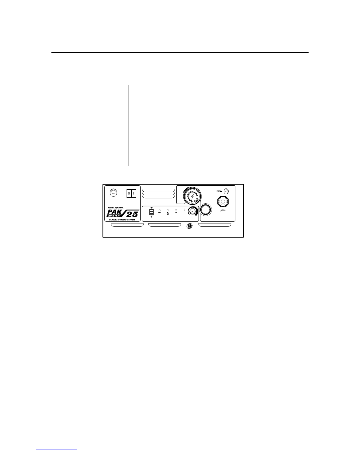
1.1 SYSTEM DESCRIPTION
The PAK MASTER® 25™
European Air Plasma
Cutting System
Includes:
Note: Handle Not Shown
• PAK MASTER 25™ EMC Model - The Power Supply provides
20 amps maximum output cutting current from a standard 110
volt, 50/60Hz AC single phase input service. All electrical,
pilot, and gas control circuitry is included.
• EMC PCH-25 Hand Torch with leads. Cut capacity is 1/4 inch
(6.4 mm) steel. Parts-In-Place (PIP) is an integral safety feature
of this torch to reduce the risk of electric shock.
• EMC PCH-25 Spare Parts Kit.
• 10 foot Work Cable with Clamp.
• 10 foot AC Input Power Cable.
AC POWERINPUT POWER
R
®
RUN
AC
SET
OPERATING
PRESSURE
50 PSI
0
6
80
(3.4 BAR)
5
4
6
40
3
100
2
bar
1
psi
20
GAS
DC
12 20
CURRENT
WORK
PRESSURE
TORCH
Made in the USA
A-01289
Figure 1-A PAK MASTER 25™ EMC Model Power Supply
Manual 0-2577 1 INTRODUCTION & DESCRIPTION
Page 16
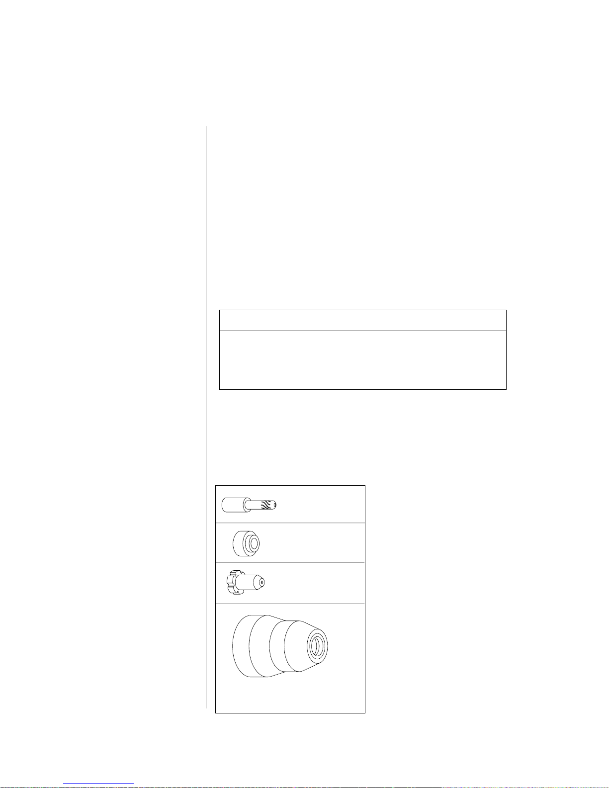
1.2 SYSTEM OPTIONS AND TORCH PARTS
System Options
Torch Parts Selection
These items can be used to customize a standard system for a
particular application or to further enhance performance.
• High Pressure Regulators - Available for air and Nitrogen (N
2
• Cutting Guide - This device provides precise cutting capability
with a hand torch. The guide fits 70° and 90° hand torches. The
kit includes roller guides and pivots that attach to the torch.
• The Leads Storage Kit (Catalog # 7-0253) - Provides a place to
store the EMC Pak Master 25 Torch Leads and is designed to
be mounted on the top of the Pak Master 25 EMC Model Power
Supply.
• Air Line Filter - Removes damaging contaminants and moisture from the air stream when using compressed air.
Recommended Air Filter Assembly
Single Stage Inline Kit ................................... Cat. No. 7-0250
Replacement Cartridge* ................................ Cat. No. 7-0251
The same torch parts are used for drag cutting and standoff
cutting. See Section 4.5, Replacing Consumable Torch Parts.
).
Order replacement parts by catalog number and description.
Address inquiries to your authorized Thermal Dynamics distributor.
Electrode
Catalog No. 9-6006
Gas Distributor
Catalog No. 9-6007
Standard Cutting Tip
Catalog No. 9-4476
Standard Shield Cup
Catalog No. 9-6003
A-00778
INTRODUCTION & DESCRIPTION 2 Manual 0-2577
Page 17

SECTION 2: INSTALLATION
2.1 UNPACKING AND CHOOSING A LOCATION
What's Included with
the Power Supply
Unpacking Procedure
Choosing a Location
Included with each system is:
(1) Work Cable with Clamp (Attached)
(1) 14 AWG Single-Phase Input Power Cable (Attached)
(1) Operating Manual................................................Cat. No. 0-2577
(1) Spare Parts Kit - Includes:
(5) Standard Tips ................................................. Cat. No. 9-4476
(3) Electrodes .......................................................Cat. No. 9-6006
(1) Gas Distributor ..............................................Cat. No. 9-6007
1. Unpack each item and remove all packing material.
2. Locate the packing list(s) and use the list to identify and
account for each item.
3. Inspect each item for possible shipping damage. If damage is
evident, contact your distributor and/or shipping company
before proceeding with system installation.
Select a clean, dry location with good ventilation and adequate
working space around all components.
The Power Supply is cooled by air flow through the front and
side panels. Air flow must not be obstructed. Provide at least 12
inches (300 mm) clearance on each side. Provide sufficient
clearance in front of the unit to allow access to front panel controls (minimum 12 in or 300 mm).
CAUTION
CAUTION
NOTE
Manual 0-2577 3 INSTALLA TION
Operation without proper air flow will inhibit proper cooling
and reduce duty cycle.
To prevent entry of cutting or other metal debris, the power
supply must not be operated in the vertical position. Operate the
power supply in the horizontal position or propped up by the
handle.
Review Important Safety Precautions (page 1) to be sure that the
selected location meets all safety requirements.
Page 18

2.2 ELECTRICAL CONNECTIONS
WARNING
Power Requirements
NOTE
CAUTION
Disconnect primary power at the source before disassembling
the power suply, torch or torch leads.
The unit will operate from single phase 110V ±10%, 50/60 Hz.
The service should be fused for 15 amps.
Input power connections can be made directly to a properly
fused disconnect or by using a plug which conforms to the
recommended ratings.
The attached AC input power cable is three conductor, 14 AWG.
The primary power source, power cable, and plug all must
conform to local elecric code and recommended circuit
protection and wiring requirements.
INST ALLA TION 4 Manual 0-2577
Page 19

2.3 GAS CONNECTIONS
Gases
Pressure
Flow
CAUTION
WARNING
CAUTION
Checking Air Quality
Filtering
Gas Connections
Compressed Air or Nitrogen (N
), Only
2
50 psi (2.8 BAR)
125 scfh (59 lpm)
Maximum input gas pressure must not exceed 125 psi (8.6 BAR).
This cutting system must not be used with Oxygen (O
).
2
Air supply must be free of oil, moisture, and other contaminants.
Excessive oil and moisture may cause double-arcing, rapid tip
wear, or even complete torch failure. Contaminants may cause
poor cutting performance and rapid electrode wear.
To test the quality of air, place a welding filter lens in front of the
torch and turn on the gas. Any oil or moisture in the air will be
visible on the lens. Do not initiate an arc!
An air line filter, capable of filtering to at least 5 microns, is
required when using air from a compressor to insure that moisture and debris from the supply hose does not enter the torch.
The front panel of the power supply is equipped with a female
1/4 NPT gas input fitting.
Using High Pressure
Gas Cylinders
NOTE
To use air or nitrogen from a high pressure gas cylinder:
1. Examine the cylinder valves to be sure they are clean and
free of oil, grease or any foreign material. Momentarily open
each cylinder valve to blow out any dust which may be
present.
2. Each cylinder must be equipped with an adjustable highpressure regulator capable of pressures up to 75 psi (5.3 BAR)
minimum and flows of up to 200 scfh (94 lpm).
3. Set the tank regulator to 75 psi (5.3 BAR). Use the regulator
on the front of the power supply to adjust the gas pressure to
the unit.
Refer to the manufacturer's specifications for installation and
maintenance procedures for high pressure gas regulators.
Manual 0-2577 5 INSTALLA TION
Page 20
Using Shop Air
CAUTION
CAUTION
Replacing Filter
Cartridge
Do not use an air line filter with high pressure gas cylinders.
To use shop air from a compressor, refer to Figure 2-B and:
Air supply must be free of oil, moisture, and other contaminants.
Excessive oil and moisture may cause double-arcing, rapid tip
wear, or even complete torch failure. Contaminants may cause
poor cutting performance and rapid electrode wear.
1. Install an air filter assembly (Cat. No. 7-0250) to the gas input
fitting on the front panel of the power supply. The air filter is
supplied with 1/4 NPT gas couplings. A quick disconnect
fitting is recommended on the filter body cap to allow easy
connection to the compressed air source.
2. Connect the air supply hose to the inlet fitting on the air filter
body cap.
When connecting a gas fitting to the filter cap, hold the cap flats
with a wrench. Over tightening the cap on the filter body can
damage the filter cartridge or cap gasket.
Air filter cartridge (Cat. No. 7-0252) should be replaced every 30
days, depending on the condition of the compressed air. If a
noticeable drop in air pressure occurs, the filter has become filled
with contaminants and must be replaced.
Front Panel 1/4 NPT
Gas Fitting
Optional
Air Line Filter
Assembly
A-01271
Using the System with Shop Air
To replace cartridge, unscrew filter cap from body, slide out old
cartridge and insert new filter element. The filter cartridge fits
only one way. Filter cap must be hand tight only.
NOTE
Supply hoses must be at least #4 hose (1/4 in or 6.4 mm minimum inside diameter).
AIR FLOW
Filter Cap
Supply Hose from Source
1/4 NPT Connection
Using the System with Cylinder Air
Figure 2-B Air Line Filter Gas Connections
Front Panel 1/4 NPT
Gas Fitting
Supply Hose from Gas
Cylinder Regulator
1/4 NPT Connection
AIR FLOW
A-01272
INST ALLA TION 6 Manual 0-2577
Page 21
SECTON 3: OPERATION
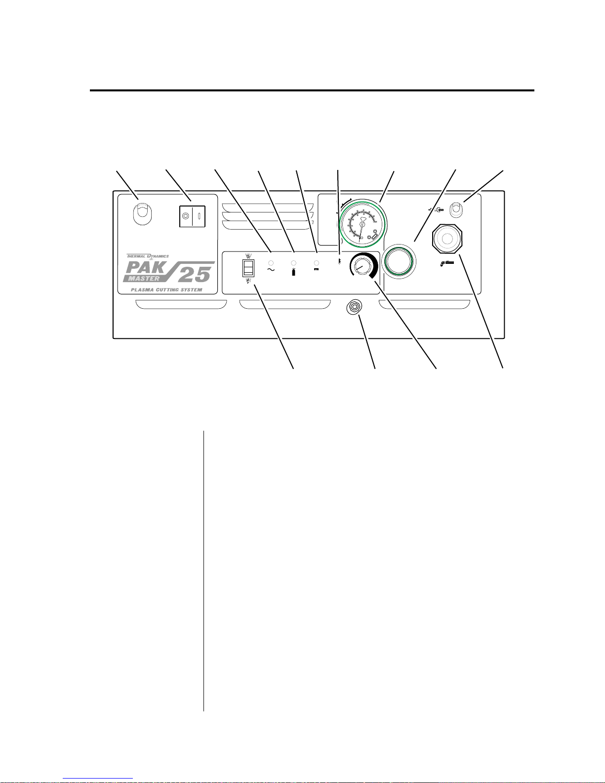
3.1 OPERATING CONTROLS
AC Power
Cable
AC Power
Switch
AC POWERINPUT POWER
®
®
Note: Handle Not Shown
A-02191
ON/OFF Switch
AC
Indicator
GAS
IndicatorDCIndicator
RUN
SET
AC
GAS
RUN/SET
DC
Switch
TEMP
Indicator
OPERATING
PRESSURE
50 PSI
(3.4 BAR)
0
4
12 20
Gas Pressure
Gauge
0
6
8
0
5
4
6
3
100
2
bar
1
psi
20
CURRENT
Gas Connect
Fitting
Gas Pressure
Control
WORK
PRESSURE
TORCH
Made in the USA
Current
Control
ON position supplies AC power to activate all system control circuits. OFF position deactivates control circuits.
WORK
Cable
TORCH
Cable
RUN/SET Switch
RUN position is used for torch operation. SET position is used for
setting gas pressure and purging lines.
AC Indicator
Yellow light indicates AC input power is present in the system when
the ON/OFF switch is in ON position. Indicator will flash for a few
seconds when first turned on until the power circuits are ready.
GAS Indicator
Yellow light (with RUN/SET switch in SET position) indicates
minimum gas pressure (35 psi or 2.5 BAR) flowing to the torch. Light
goes out in RUN position until torch is activated.
DC Indicator
Yellow light indicates adequate DC power output for main arc when
the torch is activated.
TEMP Indicator
The presence of a thermometer symbol indicates overheating; unit
must be allowed to cool. No symbol is visible during normal operation. The indicator will also flash for a moment if the torch is shorted.
Current Control
Pressure Gauge
Pressure Control
Adjusts output current from 12 to 20 amps.
Displays input pressure to the torch.
Adjusts pressure from the regulator. Pull knob out and turn clock-
wise to increase pressure to desired level. Push Knob in to lock
setting.
Manual 0-2577 7 OPERA TION
Page 22

3.2 GETTING STARTED
WARNING
Check Torch Parts
NOTE
Check Input Power
Connect Work Cable
Check Gas Supply
Select Output Current
Set Operating Pressure
Disconnect primary power at the source before disassembling
the power supply, torch, or torch leads.
Follow this set-up procedure each time the system is operated:
1. Check the torch for proper assembly and appropriate front
end torch parts (see Section 4.5, Replacing Consumable Torch
Parts).
The power supply will not operate unless the torch shield cup is
fully seated against the PIP (Parts in Place) pins in the torch
head.
2. Check the power source for proper input voltage. Make sure
the power source meets circuit protection and wiring requirements (see Section 2.2).
3. Check for a solid work cable connection to the workpiece.
4. Select desired gas (air or nitrogen). Make sure gas sources
meet pressure and flow requirements (see Section 2.3, Gas
Connections). Check connections and turn gas supply on.
5. Select the desired current output level (12 to 20 amps).
7. Move the RUN/SET switch to SET position. Adjust the gas
pressure to 50 psi (3.5 BAR).
8. Set the RUN/SET switch to RUN position.
The system is now ready for operation.
OPERATION 8 Manual 0-2577
Page 23

3.3 SEQUENCE OF OPERATION
ACTION
Plug in
Power Cord
RESULT
Power to system.
ACTION
Protect eyes and
activate torch
RESULT
Gas flows
GAS indicator ON
After gas pre-flow:
DC indicator on.
Power supply enabled.
Pilot arc established
ACTION
ON/OFF switch
to ON.
RESULT
AC Indicator flashes for
3 seconds then stays on.
Fan on.
PILOT ARC
ACTION
RUN/SET Switch to SET
RESULT
Gas solenoid open,
gas flows to set
pressure.
Gas indicator ON
if above 35 psi
ACTION
RUN/SET switch
to RUN
RESULT
Gas flow stops.
GAS indicator off.
Power circuit ready.
ACTION
Torch moved away
from work (while
still activated).
RESULT
Main arc stops.
Pilot arc auto-
matically restarts.
ACTION
Torch deactivated by torch
switch release.
RESULT
Main arc stops. Pilot stops.
(Power supply enable signal removed.)
Gas solenoid closes. Gas flow stops.
NOTE - If torch is activated during
post-flow, pilot arc will immediately restart.
If torch is within transfer distance (1/8 in) of
workpiece, main arc will transfer.
DC indicator off.
After post-flow:
GAS indicator OFF.
ACTION
ON/OFF switch
to OFF
RESULT
All indicators off.
Power supply
fan off.
Figure 3-B Sequence of Operation
ACTION
Torch moved within
transfer distance of
workpiece.
RESULT
Main arc transfer.
Pilot arc off.
DC indicator still on.
ACTION
Unplug
Power Cord
RESULT
No power to system.
A-00788
Manual 0-2577 9 OPERA TION
Page 24
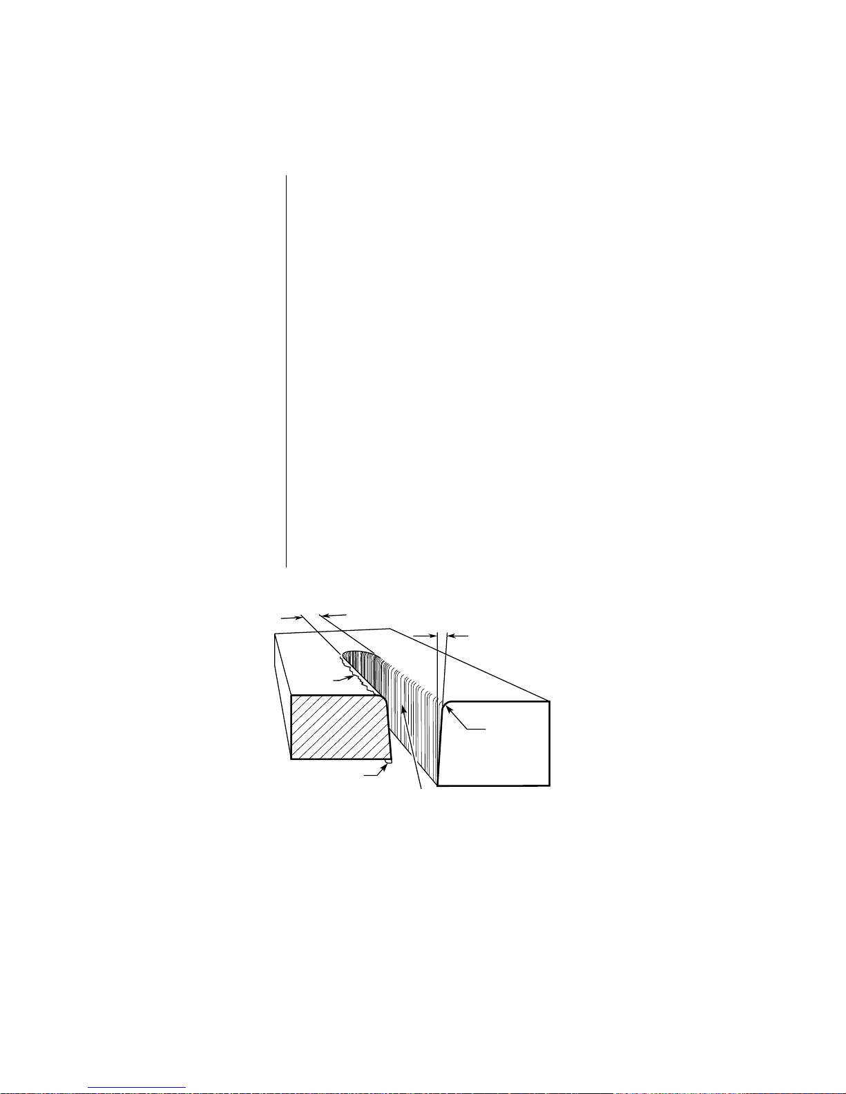
3.4 CUT QUALITY
Cut quality requirements differ depending on application. For
instance, nitride build-up and bevel angle may be major factors
when the surface will be welded after cutting. Dross-free cutting
is important when finish cut quality is desired to avoid a secondary cleaning operation. The following cut quality characteristics
are illustrated in Figure 3-C below:
Cut Surface
Bevel Angle
Top-Edge Rounding
Dross Build-up/
Top Spatter
Kerf Width
Nitride Build-up
• The condition (smooth or rough) of the face of the cut.
• The angle between the surface of the cut edge and a plane
perpendicular to the surface of the plate. A perfectly perpendicular cut would result in a 0° bevel angle.
• Rounding on the top edge of a cut due to wearing from the
initial contact of the plasma arc on the workpiece.
• Molten material which is not blown out of the cut area and resolidifies on the plate. Top spatter is dross which accumulates
on the top surface of the workpiece. Excessive dross may
require secondary clean-up operations after cutting.
• The width of material removed during the cut.
• Nitride deposits which may remain on the surface of the cut
when nitrogen is present in the plasma gas stream. Nitride
buildups may create difficulties if the material is welded after
the cutting process.
Kerf Width
Cut Surface
Bevel Angle
Top
Spatter
Figure 3-C Cut Quality Characteristics
OPERATION 10 Manual 0-2577
Dross
Build-Up
Cut Surface
Drag Lines
Top Edge
Rounding
A-00007
Page 25

GAS
MATERIAL
THICKNESS
Carbon Steel
TYPE OF MATERIAL
Stainless Steel
Aluminum
Air
Nitrogen
Gage to 1/4 in.
(Aluminum to 3/16 in.)
Table 3-A Cut Quality on Various Materials and Material Thicknesses
Description of Cut
Characteristics
NOTE
Good - Excellent
Good
Good - Excellent
Good
Good - Excellent
Good
Excellent - Minimum bevel (0 - 4°), minimum kerf (2 x tip orifice
diameter), little or no dross, smooth cut surface.
Good - Slight bevel (0 - 10°), slightly wider kerf (2-1/2 x tip
orifice diameter), some dross (easily removed), medium-smooth
cut surface, slight top edge rounding.
Fair - Excessive bevel (over 10°), wide kerf (over 2-1/2 x tip
orifice diameter), medium to heavy dross, rough cut surface, top
edge rounding.
Cut quality depends heavily on set-up and parameters such as
torch standoff, alignment with the workpiece, cutting speed, gas
pressures, and operator ability.
Manual 0-2577 11 OPERA TION
Page 26

3.5 OPERATING THE SYSTEM
WARNING
WARNING
CAUTION
NOTE
Piloting
Torch Standoff
Disconnect primary power at the source before disassembling
the power supply, torch, or torch leads.
Frequently review the Important Safety Precautions at the
beginning of this manual. Be sure the operator is equipped with
proper gloves, clothing, eye and ear protection. Make sure no
part of the operator’s body comes into contact with the workpiece while the torch is activated.
Sparks from the cutting process can cause damage to coated,
painted, and other surfaces such as glass, plastic and metal.
Handle torch leads with care and protect them from damage.
Piloting is harder on parts life than actual cutting because the
pilot arc is directed from the electrode to the tip rather than to a
workpiece. Whenever possible, avoid excessive pilot arc time to
improve parts life.
Improper standoff (the distance between the torch tip and
workpiece) can adversely affect tip life as well as shield cup life.
Standoff may also significantly affect the bevel angle. Reducing
standoff will generally result in a more square cut.
Edge Starting
Direction of Cut
Dross
For edge starts, hold the torch perpendicular to the workpiece
with the front of the tip on the edge of the workpiece at the point
where the cut is to start. When starting at the edge of the plate,
do not pause at the edge and force the arc to "reach" for the edge
of the metal. Establish the cutting arc as quickly as possible.
In the torch, the plasma gas stream swirls as it leaves the torch to
maintain a smooth column of gas. This swirl effect results in one
side of a cut being more square than the other. Viewed along the
direction of travel, the right side of the cut is more square than
the left (see Figure 3-C). To make a square-edged cut along an
inside diameter of a circle, the torch should move counter clockwise around the circle. To keep the square edge along an outside
diameter cut, the torch should travel in a clockwise direction.
On carbon steel, dross on top of the plate is normally caused by a
fast torch travel speed or a high torch standoff. This dross is
usually hard to remove. Dross along the cut line on the bottom of
the plate is more easily removed and is often caused by torch
travel speeds that are to slow.
OPERATION 12 Manual 0-2577
Page 27

Common Cutting Faults
Problem
Insufficient
Penetration
Main Arc
Extinguishes
Excessive
Dross Formation
Short Torch
Parts Life
Possible Cause
1. Cutting speed too fast
2. Torch tilted too much
3. Metal too thick
4. Worn torch parts
5. Cutting current too low
1. Cutting speed too slow
2. Torch standoff too high from workpiece
3. AC line too low - reduce output current
4. Work cable disconnected
5. Worn torch parts
1. Cutting speed too slow (bottom dross)
2. Cutting speed too fast (top dross)
3. Torch standoff too high from workpiece
4. Worn torch parts
5. Improper cutting current
1. Oil or moisture in air source
2. Exceeding system capability (material too thick)
3. Excessive pilot arc time
4. Air flow too low (incorrect pressure)
5. Improperly assembled torch
Table 3-B Common Causes of Operating Problems
Manual 0-2577 13 OPERA TION
Page 28

3.6 OPERATING WITH A HAND TORCH
Cutting with a
Hand Torch
1. The torch can be comfortably held in one hand or steadied
with two hands. Choose the technique that feels most comfortable and allows good control and movement. Position the
index finger or thumb to press the control switch on the torch
handle.
2. For edge starts, hold the torch perpendicular to the workpiece
with the front of the tip on the edge of the workpiece at the
point where the cut is to start. For piercing, angle the torch
slightly to direct sparks away from the torch until the pierce
is complete.
3. For drag cuts keep the torch in contact with the workpiece.
For standoff cutting, hold the torch 1/16 -1/8 in (2-3 mm)
from the work.
4. With the torch in starting position, press and hold the control
switch. After an initial gas purge, the pilot arc will come on
and remain on until the cutting arc starts.
5. Once on, the main arc remains on as long as the control
switch is held down, unless the torch is withdrawn from the
work or torch motion is too slow. If the cutting arc is interrupted, the pilot arc comes back on automatically.
6. To shut off the torch simply release the control switch. When
the switch is released a ten second post-flow will occur. If the
torch switch is closed during the post-flow, the cutting arc
will restart immediately when the torch is brought within
range of the workpiece.
Piercing with a
Hand Torch
OPERATION 14 Manual 0-2577
1. When piercing with a hand torch, tip the torch slightly so
that blowback particles blow away from the torch tip (and
operator) rather than directly back into it.
2. Complete the pierce off the cutting line and then continue the
cut onto the line. Hold the torch perpendicular to the workpiece after the pierce is complete.
3. Clean spatter and scale from the shield cup and the tip as
soon as possible. Spraying or dipping the shield cup in antispatter compound will minimize the amount of scale which
adheres to it.
Page 29

3.7 RECOMMENDED CUTTING SPEEDS
Recommended
Cutting Speeds
Cutting speed depends on material, thickness, and the operator’s
ability to accurately follow the desired cut line. The following
factors may have an impact on system performance:
• Torch parts wear
• Air quality
• Line voltage fluctuations
• Torch standoff height
• Proper work cable connection
NOTE
This information represents realistic expectations using recommended practices and well-maintained systems. Actual speeds
may vary up to 50% from those shown.
Material Thickness Cut Speed (IPM) Amps Gas / Pressure Stand Off
MILD STEEL 26 gauge 250 20 Air / 50 psi Drag - 1/8"
20 gauge 125 20 Air / 50 psi Drag - 1/8"
1/16" (1.6 mm) 85 20 Air / 50 psi Drag - 1/8"
1/8" (3.2 mm) 25 20 Air / 50 psi Drag - 1/8"
3/16" (4.8 mm) 15 20 Air / 50 psi Drag - 1/16"
1/4" (6.4 mm) 8 20 Air / 50 psi Drag - 1/16"
Material Thickness Cut Speed (IPM) Amps Gas / Pressure Stand Off
STAINLESS 20 gauge 125 20 Air / 50 psi Drag - 1/8"
STEEL 1/16" (1.6 mm) 40 20 Air / 50 psi Drag - 1/8"
1/8" (3.2 mm) 25 20 Air / 50 psi Drag - 1/8"
3/16" (4.8 mm) 10 20 Air / 50 psi Drag - 1/16"
Material Thickness Cut Speed (IPM) Amps Gas / Pressure Stand Off
GALVANIZED 24 gauge 100 20 Air / 50 psi Drag - 1/8"
STEEL 20 gauge 75 20 Air / 50 psi Drag - 1/8"
18 gauge 65 2 0 Air / 50 psi Drag - 1/8"
1/16" (1.6 mm) 45 20 Air / 50 psi Drag - 1/8"
5/64" (2.0 mm) 30 20 Air / 50 psi Drag - 1/8"
Tables 3-D Recommended Cutting Speeds
Manual 0-2577 15 OPERA TION
Page 30

Material Thickness Cut Speed (IPM) Amps Gas / Pressure Stand Off
ALUMINUM 24 gauge 25 0 20 Air / 50 psi Drag - 1/8"
22 gauge 200 20 Air / 50 psi Drag - 1/8"
1/16" (1.6 mm) 150 20 Air / 50 psi Drag - 1/8"
3/32" (2.4 mm) 25 20 Air / 50 psi Drag - 1/8"
1/8" (3.2 mm) 10 20 Air / 50 psi Drag - 1/8"
Tables 3-D Recommended Cutting Speeds (continued)
OPERATION 16 Manual 0-2577
Page 31

SECTION 4: CUSTOMER/OPERATOR SERVICE
4.1 POWER SUPPLY SPECIFICATIONS
Controls
Panel Indicators
Input Power
Output Power
OCV
Duty Cycle
Work Lead
Cut Capacity
Pilot Circuitry
Gas Connection
Weight
• ON/OFF Switch
• RUN/SET Switch
• Output Current Control
• Pressure Regulator Control
LED Indicators: AC Power, GAS, DC, TEMP
Pressure Gauge
110 VAC (±10%), 50/60 Hz, 15 Amp Single Phase
Continuously variable from 12 to 20 Amps maximum
375 VDC
40%
10 ft (3 m) with clamp
1/4 in (6.4 mm) Steel
Capacitor Discharge (CD), Pulsed DC
Front panel entry 1/4 NPT
42.5 lbs (19.3 kg)
Manual 0-2577
13.25 in
O
R
K
R
C
H
U
S
A
17.5 in
(445 mm)
(191 mm)
I
N
Note:
(337 mm)
P
U
T
P
O
W
E
R
A
C
P
O
W
E
R
R
R
S
O
PERATING
PRESS
URE
50 PSI
(3.4 BAR
)
R
U
N
A
C
G
A
S
E
T
W
P
R
E
S
S
U
R
E
D
C
T
O
1
2
2
0
C
U
R
R
E
N
T
M
a
d
e
in
t
h
e
Handle Not Shown
A-01293
Figure 4-A Power Supply Dimensions
17
CUSTOMER/OPERATOR SERVICE
7.5 in
Page 32
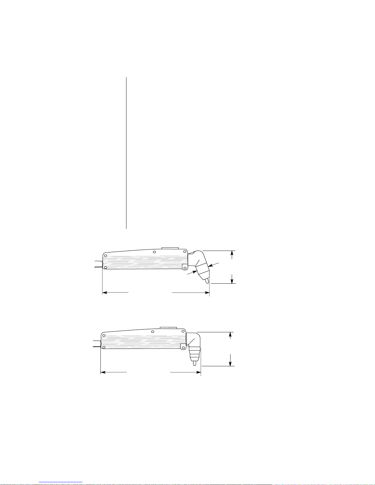
4.2 TORCH SPECIFICATIONS
Configuration
Current Rating
Duty Cycle
Cutting Range
Pierce Rating
Transfer Distance
Consumable Parts
Gases
Pressure Requirements
Flow Requirements
Lead Length
70º or 90° Hand Torch
20 Amps Maximum, DC Straight Polarity
100%
Most materials up to 1/4 in (6.4 mm)
1/8 in (3.2 mm)
1/8 in (3.2 mm)
Gas Distributor, Electrode, Tip, Shield Cup
Compressed Air or Nitrogen (N
) Only
2
50 psi (3.5 BAR)
125 scfh (49 lpm)
12.5 ft (3.8 m) or 25 ft (7.6 m)
2.95 in
(75 mm)
1.06 in (27 mm)
7.98 in (203 mm)
3.13 in
(80 mm)
7.31 in (186 mm)
Figure 4-B PCH-25 Torch Dimensions
70˚
90˚
A-00779
CUSTOMER/OPERATOR SERVICE
18
Manual 0-2577
Page 33

4.3 REPLACEMENT TORCHES AND LEADS
Ordering Information
Order replacement parts by catalog number and complete
description of the part , including model number of the torch, as
listed in the description column. Address all inquiries to your
authorized Thermal Dynamics distributor.
If a Thermal Dynamics product must be returned for service,
contact your Thermal Dynamics distributor. Materials returned
to Thermal Dynamics without proper authorization will not be
accepted.
Manual 0-2577
19
CUSTOMER/OPERATOR SERVICE
Page 34
4.4 BASIC TROUBLESHOOTING GIUIDE AND MAINTENANCE
General
Routine Maintenance
WARNING
CAUTION
Basic troubleshooting of the Pak Master 25 EMC Model Plasma
Cutting System can be performed without special equipment or
knowledge, and without opening the enclosure.
This basic troubleshooting guide covers input power, gas supply, and torch problems.
For problems not covered here, contact your authorized Thermal
Dynamics distributor.
If a Thermal Dynamics product must be returned for service,
contact your Thermal Dynamics distributor. Materials returned
to Thermal Dynamics without proper authorization will not be
accepted.
The only routine maintenance required for the power supply is a
thorough cleaning and inspection, with the frequency depending
on the usage and the operating environment.
Disconnect primary power to the system before disassembling
the torch, leads, or power supply.
Do not blow air into the power supply during cleaning. Blowing
air into the unit can cause metal particles to interfere with
sensitive electrical components and cause damage to the unit.
To clean the unit, open the enclosure (see Section 4.8) and use a
vacuum cleaner to remove any accumulated dirt and dust. The
unit should also be wiped clean. If necessary, solvents that are
recommended for cleaning electrical apparatus may be used.
When cleaning care must be taken not to move or damage the
CAUTION
CUSTOMER/OPERATOR SERVICE
electronic components.
20
Manual 0-2577
Page 35

SYMPTOM POSSIBLE CAUSE REMEDY
A. AC indicator not lighted.
Fan does not turn.
B. AC indicator lighted.
(TEMP) indicator lighted.
C. AC indicator lighted,
(TEMP) indicator dark, no
gas flow in SET.
D. AC indicator lighted,
(TEMP) indicator dark, no
gas flow in RUN when
torch swirch pressed.
1. Circuit Breaker open.
1. Unit is overheated.
2. Airflow obstructed.
3. Pilot circuit overheated.
Temp indicator lits momentarily and unit shuts
down.
1. Gas not connected or
pressure too low.
2. Air filter or air line blocked
(GAS indicator dark).
Torch leads blocked (GAS
indicator lit).
1. Sheild cup not properly
installed on torch.
2. Faulty PIP assembly in
torch holder.
1. Reset Breaker. Use 15
amp or greater service.
1. Make sure the unit has
not been operated
beyond 40% duty cycle
limit.
2. Provide at least 12 inch
clearance on each side.
3. Check for proper torch
parts assembly, or for
shorted torch head. See
Section 4.5
1. Check source for at
least 50 psi (3.5 BAR).
In SET position, adjust
gas pressure to 50 psi.
2. Replace filter cartridge.
Check that air lines and
torch leads are free of
twists and kinks.
1. Check that shield cup
is fully seated against
torch head.
2. See Servicing Torch
Head Components,
Section 4.7
E. AC indicator lighted,
(TEMP) indicator dark, GAS
indicator lighted, gas flows,
DC indicator lit. Torch does
not pilot.
F. Torch pilots but does not
cut.
Manual 0-2577
1. Faulty torch parts
2. Gas pressure too high.
1. Work lead not connected.
2. AC input too low.
21
1. Inspect torch parts and
replace if necessary.
See Section 4.5
2. Set pressure to 50 psi
(3.5 BAR).
1. Make sure work lead is
connected securely to
bare metal.
2. Check that AC plug to
line cord connections
are tight.
CUSTOMER/OPERATOR SERVICE
Page 36

4.5 REPLACING CONSUMABLE TORCH PARTS
WARNING
WARNING
NOTE
Disconnect primary power to the system before disassembling
the torch, leads, or power supply.
DO NOT TOUCH internal torch parts while the AC indicator on
the front panel of the power supply is lit.
The tip, gas distributor, and electrode are held in place by the
shield cup. Position the torch with the shield cup facing upward
to prevent these parts from falling out when the cup is removed.
Refer to Figure 4-C and:
1. Unscrew and remove the shield cup from the torch. Inspect
the cup for damage. Wipe it clean or replace if damaged.
2. Remove the tip. Check for excessive wear (indicated by an
elongated or oversized orifice). Clean and replace the tip if
necessary.
3. Remove the gas distributor and check for excessive wear,
plugged gas holes, or discoloration. Replace if necessary.
4. Remove the electrode. The face of the electrode should not be
recessed more than 0.10 inch (2.5 mm). If it is worn beyond
this point it must be replaced.
CAUTION
A-00780
5. Reinstall the parts and shield cup on the torch as shown.
Hand tighten the shield cup until it is seated on the torch
head. If resistance is felt when installing the cup, check the
threads before proceeding with installation.
Improper assembly or use of non standard torch parts can cause
the torch head to short and may overheat or damage the torch.
Gas
Distributor TipElectrode
Torch Head Assembly
Standard
Shield Cup
Figure 4-C PCH-25 Consumable Parts
CUSTOMER/OPERATOR SERVICE
22
Manual 0-2577
Page 37
4.6 GENERAL TORCH MAINTENANCE
Cleaning the Torch
WARNING
WARNING
CAUTION
Even if precautions are taken to use only clean air with a torch,
eventually the inside of the torch becomes coated with residue.
This buildup can affect the pilot arc initiation and the overall cut
quality of the torch.
Disconnect primary power to the system before disassembling
the torch, leads, or power supply.
DO NOT touch any internal torch parts while the AC indicator
light on the front panel of the power supply is lighted.
The inside of the torch should be cleaned with electrical contact
cleaner using a cotton swab or soft wet rag. In severe cases, the
torch can be removed from the leads (see Section 4.7, Servicing
Torch Head Components) and cleaned more thoroughly by
pouring electrical contact cleaner into the torch and blowing it
through with compressed air.
Dry the torch thoroughly before reinstalling.
Manual 0-2577
23
CUSTOMER/OPERATOR SERVICE
Page 38
4.7 SERVICING TORCH HEAD COMPONENTS
WARNING
WARNING
Tools Required
Removing Torch Head
Disconnect primary power to the system before disassembling
the torch, leads, or power supply.
NEVER touch any internal torch parts while the AC indicator
light on the front panel of the control module is lit.
(1) No. 1 Phillips Head Screwdriver
(2) 1/4 in Open End Wrenches
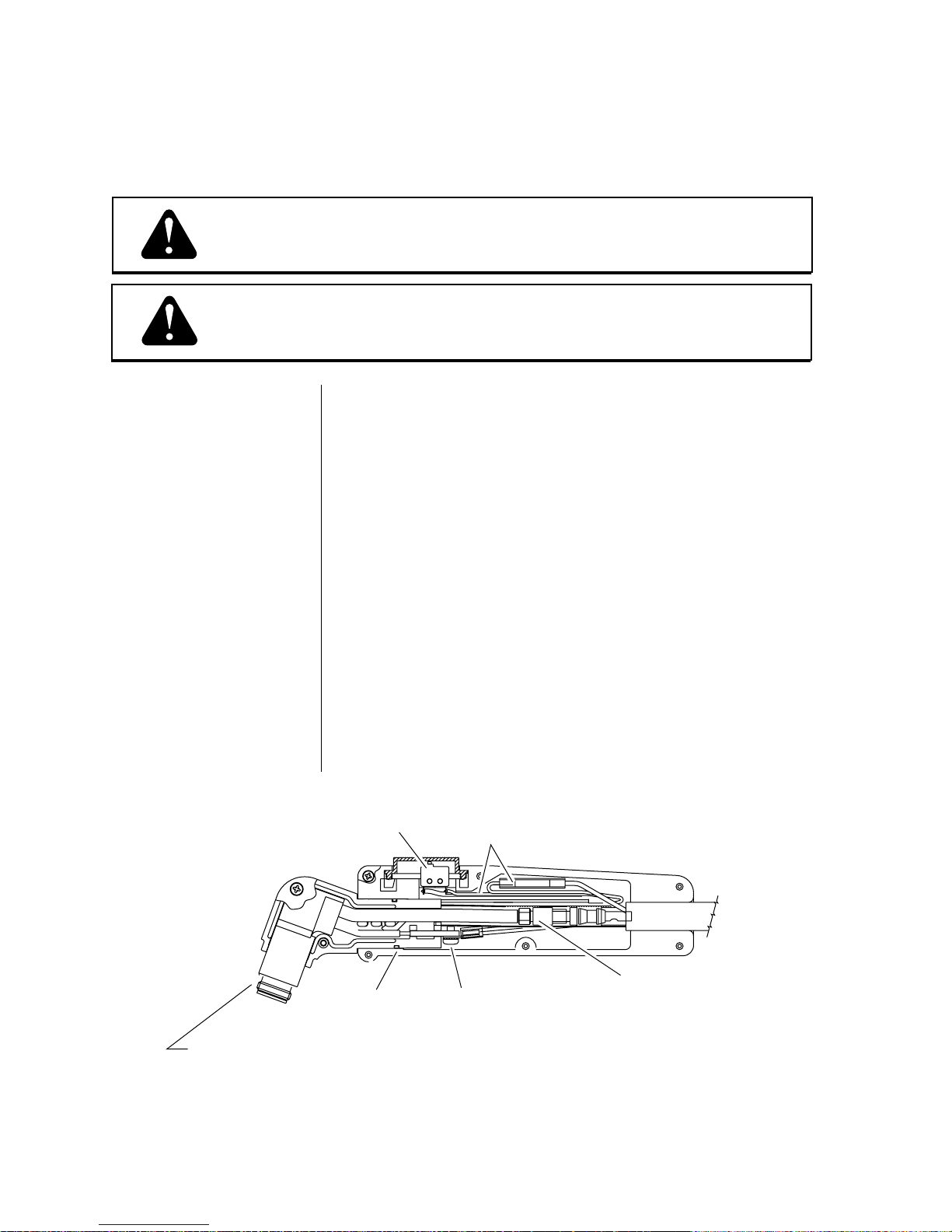
Refer to Figure 4-D and:
1. Remove the six screws from the torch handle assembly. Pull
the cover off the handle to expose the leads and torch
switch/PIP connections.
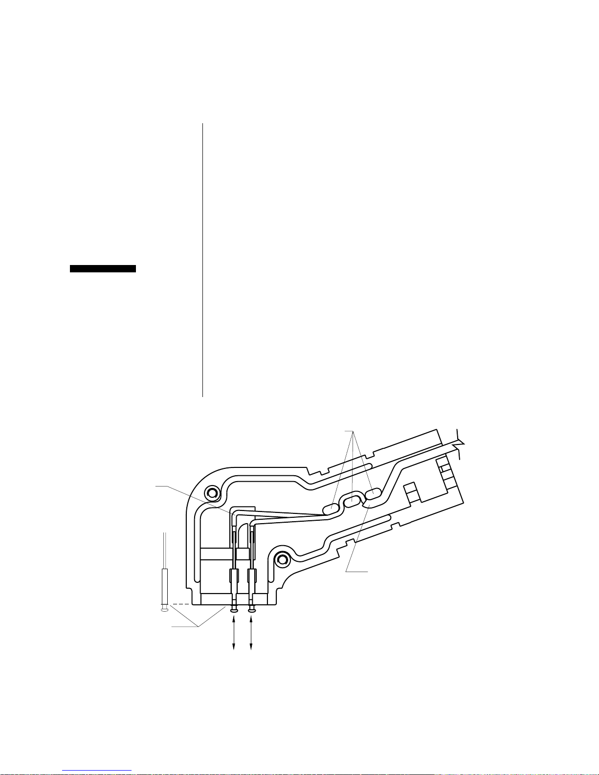
Refer to Figure 4-E and:
2. Disconnect the negative/plasma and pilot lead connection at
the torch head.
3. Slip off the rear O-Ring, remove the two screws from the
torch head housing, and seperate the halves. Remove the
torch head from the housing.
4. Carefully remove the torch switch and switch button from
the handle. Make sure the two small springs stay in place on
the switch button. Do not disturb the PIP wiring in the torch
head housing.
Torch Switch
Torch Handle
O-Ring
Remove consumables from front end
and remove screws to allow disassembly
Figure 4-D PCH-25 Torch Head Assembly in Handle
PIP/Torch Switch
Connections
Pilot Lead Connection
Negative/Plasma
Lead Connection
A-00781
CUSTOMER/OPERATOR SERVICE
24
Manual 0-2577
Page 39

Position PIP wires
in notches in back
of split holder
Align notch on
pilot lead with
notch in split holder
Handle O-Ring
(position in rear groove)
Mounting Screws
WARNING
Replacing the
PIP Assembly
CAUTION
A-00782
PIP Pin Assemblies
Figure 4-E Disassembling the Split Holder
Disconnect primary power to the system before disassembling
the torch, leads, or power supply.
Refer to Figure 4-F and:
1. Carefully remove the PIP wires from the strain relief bosses
inside the split holder.
2. Slide the PIP pin receptacles forward out of the retention
slots.
Do not lift the PIP pin receptacles out of the split holder. Damage to holder and/or PIP pin receptacles may occur.
3. Install replacement PIP pin assemblies by positioning the
square solder post of the PIP pin receptacle in the retention
slot in the split holder and sliding the assembly up into place.
Position the flange on the PIP pin receptacle flush with the
front face of the split holder.
Manual 0-2577
4. Route the PIP wires around the strain relief bosses as shown.
Push the teflon insulation on each PIP wire up to the strain
relief boss closest to the back of the split holder for voltage
insulation from the brass pilot lead connector.
25
CUSTOMER/OPERATOR SERVICE
Page 40
Replacing the
PIP Assembly
(continued)
5. Position both PIP leads through the notch where the negative/plasma lead exits the holder.
6. Position the torch head inside the holder. Align the notch on
the pilot lead with the corresponding tab on the split holder.
Make sure the negative/plasma fitting is securely inserted in
the groove in the holder. Make sure the crescent on the torch
head is inserted into the mating groove in the holder.
7. Place the second half of the holder over the torch head.
Confirm that the PIP pin assemblies, PIP leads, and the
negative/plasma and pilot leads are properly positioned.
CAUTION
Reassembling
the Torch Head
Bend wires to
fit grooves
Do not force the holder together. Damage to the insulation on the
leads will cause torch head failure. The PIP leads must be positioned correctly to allow reassembly of the torch head.
Refer to Figure 4-E and:
1. Install the two assembly screws to secure the split holder and
reinstall the O-ring in the rear groove on the back of the torch
head assembly.
Refer to Figure 4-C and:
2. Install the front end torch parts.
Position PIP wires
through strain relief
bosses as shown
Position flange
on PIP receptacle flush
with face of split holder.
Install wire A first, then wire B.
Figure 4-F Installing a Replacement PIP Assembly
CUSTOMER/OPERATOR SERVICE
AB
Teflon wire coating
must cover wire up
to strain relief area.
Remove and install PIP assemblies
from the front. Position assemblies
in slots in split holder.
26
A-00783
Manual 0-2577
Page 41

WARNING
Disconnect primary power to the system before disassembling
the torch, leads, or power supply.
Reassembling the
Torch Handle and
Switch Assembly
NOTE
Refer to Figure 4-D and:
1. Connect the plasma and pilot lead connections at the torch
head.
2.Place the torch head in the handle and carefully return the
torch switch and button to their proper position.
Make sure torch switch and PIP wires are seated in their
guides so that the wires are not pinched when the handle is
secured.
3.Replace the cover on the handle assembly and tighten the six
retaining screws.
Manual 0-2577
27
CUSTOMER/OPERATOR SERVICE
Page 42

4.8 REPLACING TORCH AND LEADS
WARNING
Open Power Supply
Enclosure
NOTE
NOTE
Disconnect primary power to the system before disassembling
the torch, leads, or power supply.
Refer to Figure 4-G and:
1. Swing the handle into the forward position before removing
any hardware.
2. Remove the six screws on the top of the unit and six screws
on the sides of the unit.
Do not remove the two screws holding the handle to the case or
the single screw on the rear panel.
3. Slide the cover straight up and off the power supply. Pivot
the cover over the torch lead, work lead, and power cord and
rest the cover in front of the power supply.
Make certain not to strain the ground wire connection to the
cover of the power supply.
6 Screws
On Top Of Unit
I
N
P
U
T
P
O
W
E
R
A
C
P
O
W
E
R
O
P
E
R
A
T
IN
G
P
R
E
S
S
U
R
E
5
0
P
S
I
(3
.
4
B
A
R
R
R
)
R
U
N
A
C
P
G
R
A
E
S
S
D
C
S
E
T
1
2
2
0
C
U
R
R
E
N
T
Do Not Remove
Single Screw At Rear Panel
W
O
R
K
S
U
R
E
T
O
R
C
H
Made in the USA
A-01296
Do Not Remove Handle Screw
Figure 4-G Opening Power Supply for Torch Leads Replacement
CUSTOMER/OPERATOR SERVICE
(Handle Not Shown)
28
Lift Cover
6 Screws
(3 Per Side)
Manual 0-2577
Page 43

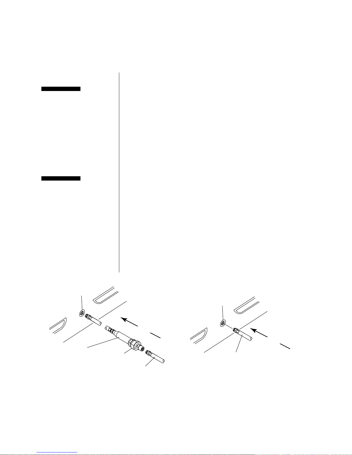
LocateTorch
Bulkhead
The torch bulkhead is located directly behind the torch lead
panel strain relief. Refer to Photo 4-A and:
1. Remove the nylon screw holding the protective insulating
sheet to the bulkhead.
Replace Leads
CAUTION
2. Loosen the torch lead strain relief nut inside the front panel.
Do not remove the strain relief from the leads. Replacement
torch leads are provided with strain reliefs.
3. Disconnect the two pin torch switch connector (white and
black wires) and the red pilot wire (terminal 2) from the
main pcb side connectors.
4. Use a 3/8 in open end wrench to loosen the negative lead
fitting to the brass torch bulkhead.
Be sure all wires are outside the protective insulating sheet when
it is reinstalled (as seen in Photo 4-A). High voltage is present on
the torch negative lead.
Torch Lead Strain Relief
Protective insulating sheet.
Use 3/8 in wrench to remove
torch negative lead.
EMC drain wire to
chassis ground
Red pilot wire (#2)
Two Pin Torch Switch Connector
Manual 0-2577
Photo 4-A Torch Lead Bulkhead Connections
29
CUSTOMER/OPERATOR SERVICE
Page 44

CUSTOMER/OPERATOR SERVICE
30
Manual 0-2577
Page 45

SECTION 5: PARTS LISTS
5.1 REPLACEMENT COMPLETE ASSEMBLIES
Description Qty. Catalog #
Complete PM 25 EMC Model 110V Systems:
Power Supply, PCH-25 Torch (70 degree)
12.5 ft (3.8 m) Leads 1 1-0280
Power Supply, PCH-25 Torch (70 degree)
25 ft (7.6 m) Leads 1 1-0281
Power Supply, PCH-25 Torch (90 degree) 1 1-0282
12.5 ft (3.8 m) Leads
Power Supply, PCH-25 Torch (90 degree) 1 1-0283
25 ft (7.6 m) Leads
Replacement Hand Torches with Leads:
PCH-25 70° Hand Torch, 12.5 ft (3.8 m) Leads 1 2-0280
PCH-25 70° Hand Torch, 25 ft (7.6 m) Leads 1 2-0281
PCH-25 90° Hand Torch, 12.5 ft (3.8 m) Leads 1 2-0282
PCH-25 90° Hand Torch, 25 ft (7.6 m) Leads 1 2-0283
Replacement Torch Leads:
Replacement EMC Leads - 12.5 ft (3.8 m) 1 4-5098
Replacement EMC Leads - 25 ft (7.6 m) 1 4-5099
Power Supply Console Only: 1 3-0280
Manual 0-2577
31
PARTS LISTS
Page 46

5.2 REPLACEMENT HAND TORCH PARTS
Item # Qty Description Catalog #
1 1 Assembly, PIP (Parts-In-Place) Pins and Wire 9-6290
2 2 O-Ring 8-0533
3 1 Holder, Torch, Split, PCH25 70° Two Parts w/Screws 9-6259
1 Holder, Torch, Split, PCH25 90° Two Parts w/Screws 9-6260
4 1 Assembly, Basic Head, PCH25 70° 9-5807
1 Assembly, Basic Head, PCH25 90° 9-5808
5 1 Distributor, Gas 9-6007
6 1 Tip, Air, 0.031 Orifice, Drag Cutting 9-4476
7 1 Electrode, Air 9-6006
8 1 Shield Cup, Standard 9-6003
9 1 Handle, Split, PCH-25 Two Parts (Includes items #14 thru#16) 9-6282
10 1 EMC Lead Assembly, Composite Cable
12.5 ft (3.8m) Length 4-5098
25 ft (7.6m) Length 4-5099
11 1 Switch, Torch 9-1058
12 1 #6-32 x 3/16 Phillips Pan Head Screw See Note
13 1 #6 Internal Star Washer See Note
14 1 Button, Split Holder 8-4256
15 2 Spring 8-4256
16 6 #2-56 x 5/16" Phillips Pan Head Screw See Note
NOTE: Item can be purchased locally.
.
9
14
10
1
PARTS LISTS
11
15
2
3
13
12
3
7
5
6
8
4
32
9
16
A-00800
Manual 0-2577
Page 47

5.3 MISCELLANOUS PARTS
Qty Description Catalog #
1 Air Regulator/Gauge Assembly (see note)
For units with rev letter 'F' or earlier 9-6283
For units with rev letter 'G' or later 9-6898
1 Cover, Grey, No Labels 9-6284
1 Torch Parts Label 9-6285
1 Warning Label 9-6286
1 PakMaster 25 Labels, Side (2 Required) 9-6287
1 Handle for Power Supply 9-6288
NOTE: Revision letter of the unit is the letter at the end of the unit serial number .
Manual 0-2577
A-00791
Air Regulator/Gauge Assembly
33
PARTS LISTS
Page 48
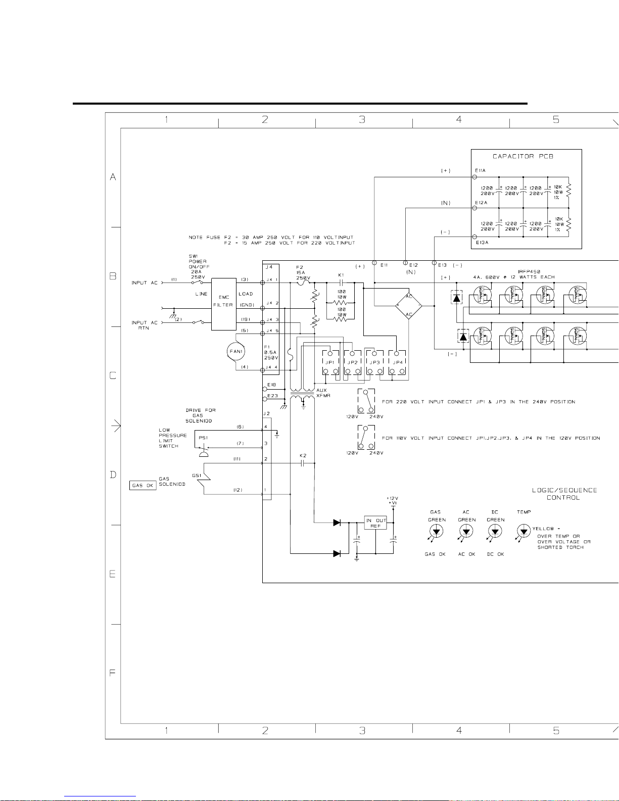
APPENDIX I: SYSTEM SCHEMATIC
A-00801
APPENDIX
34
Manual 0-2577
Page 49

A-00801
Manual 0-2577
35
APPENDIX
Page 50

 Loading...