

Page 1

PLASMA CUTTING
POWER SUPPLY
Drag-Gun™ 38
Used With PCH-42 RPT SureLok™ Torch
K
R
O
W
H
C
R
O
p
u
C
d
l
e
i
s
t
h
S
n
e
r
n
p
o
i
,
o
r
T
d
o
p
.
f
e
r
e
e
e
c
m
t
i
y
n
.
l
f
i
r
a
i
r
o
r
r
b
o
m
a
c
s
t
.
o
a
C
r
m
"
e
,
a
u
x
d
e
d
a
1
b
w
E
G
.
e
d
e
i
s
e
t
z
r
0
i
s
e
a
t
a
w
s
s
g
A
r
n
e
iv
i
n
e
d
a
s
d
e
D
v
H
o
n
s
h
l
a
d
o
t
.
u
e
e
e
o
h
o
o
c
e
r
H
r
t
r
x
c
-
N
c
f
r
o
h
e
e
6
o
c
g
l
r
o
m
r
0
t-
o
o
E
T
o
l
f
5
k
u
7
T
a
c
6
f
o
0
t
-
ip
a
r
5
t
o
a
1
9
b
o
6
0
C
d
-
y
f
n
5
)
3
n
l
9
r
e
6
0
a
m
o
-
b
c
i
0
f
9
m
e
w
i
6
r
m
d
-
5
if
.
o
e
o
9
2
r
(
e
t
s
p
i
d
c
n
t
s
i
o
le
k
r
1
A
.
t
c
0
e
c
r
e
e
le
h
e
h
e
n
C
t
p
o
.
k
e
i
o
)
c
c
t
r
e
m
p
la
i
P
h
r
p
m
C
c
e
r
5
s
.
R
o
e
2
t
(
u
e
D
t
b
d
i
r
r
o
a
t
r
t
P
s
i
c
T
e
D
p
l
N
u
s
E
S
E
C
a
T
G
d
M
p
l
R
i
E
e
A
i
T
C
h
P
A
S
H
L
C
P
E
R
R
O
T
23x4334 REV A
TM
M
A
D
E
I
N
T
H
E
U
S
A
T
A
S
U
E
H
T
IN
M
T
V
O
T
C
D
S
A
G
C
A
R
®
23x4334 REV A
E
D
A
M
0
2
9
2
R
E
P
M
E
T
2
N
1
E
R
R
U
C
A
S
U
TM
E
H
T
N
I
E
D
A
M
A-02145
Instruction Manual
December 9, 2002 Manual No. 0-2879
Page 2

Page 3

WARNINGS
Read and understand this entire Manual and your employer’s safety practices before installing, operating, or servicing the equipment.
While the information contained in this Manual represents the Manufacturer's best judgement, the
Manufacturer assumes no liability for its use.
Plasma Cutting Power Supply
Drag-Gun™ 38
Instruction Manual Number 0-2879
Published by:
Thermal Dynamics Corporation
82 Benning Street
West Lebanon, New Hampshire, USA 03784
(603) 298-5711
www.thermadyne.com
Copyright 2001 by
Thermal Dynamics Corporation
All rights reserved.
Reproduction of this work, in whole or in part, without written permission of the publisher is prohibited.
The publisher does not assume and hereby disclaims any liability to
any party for any loss or damage caused by any error or omission in
this Manual, whether such error results from negligence, accident, or
any other cause.
Printed in the United States of America
Publication Date: December 9, 2002
Record the following information for W arranty purposes:
Where Purchased: _______________________________________
Purchase Date: _______________________________________
Power Supply Serial #: _______________________________________
Torch Serial #: _______________________________________
Page 4

TABLE OF CONTENTS
SECTION 1:
GENERAL INFORMATION ............................................................................................... 1-1
1.01 Notes, Cautions and Warnings ..................................................................... 1-1
1.02 Important Safety Precautions ....................................................................... 1-1
1.03 Publications.................................................................................................. 1-2
1.04 Note, Attention et Avertissement .................................................................. 1-3
1.05 Precautions De Securite Importantes........................................................... 1-3
1.06 Documents De Reference ............................................................................ 1-5
1.07 Declaration of Conformity ............................................................................. 1-7
1.08 Statement of Warranty.................................................................................. 1-8
SECTION 2:
INTRODUCTION & DESCRIPTION.................................................................................. 2-1
2.01 Scope of Manual .......................................................................................... 2-1
2.02 General Description ..................................................................................... 2-1
2.03 Specifications & Design Features................................................................. 2-1
SECTION 3:
INST ALLATION PROCEDURES ....................................................................................... 3-1
3.01 Introduction .................................................................................................. 3-1
3.02 Site Location ................................................................................................ 3-1
3.03 Unpacking .................................................................................................... 3-1
3.04 Handle Installation........................................................................................ 3-1
3.05 Electrical Connection ................................................................................... 3-1
3.06 Torch Connection ......................................................................................... 3-2
SECTION 4:
OPERATION ..................................................................................................................... 4-1
4.01 Introduction .................................................................................................. 4-1
4.02 Operating Controls ....................................................................................... 4-1
4.03 Getting Started ............................................................................................. 4-1
4.04 Operating the System .................................................................................. 4-2
4.05 Recommended Cutting Speeds.................................................................... 4-3
SECTION 5:
SERVICE ......................................................................................................................... 5-1
5.01 Introduction .................................................................................................. 5-1
5.02 General Maintenance................................................................................... 5-1
5.03 Common Operating Faults ........................................................................... 5-1
5.04 Troubleshooting Guides................................................................................ 5-2
5.05 Basic T roubleshooting Guide........................................................................ 5-2
5.06 Advanced T roubleshooting Guide ................................................................. 5-3
5.07 T roub leshooting Flow Charts........................................................................ 5-3
5.08 Test Procedures ......................................................................................... 5-10
5.09 Power Supply Component Replacement Procedures................................. 5-15
5.10 T orch and Leads Replacement Procedure ................................................. 5-20
Page 5

TABLE OF CONTENTS (continued)
SECTION 6:
PARTS LISTS.................................................................................................................... 6-1
6.01 Introduction .................................................................................................. 6-1
6.02 Ordering Information .................................................................................... 6-1
6.03 Power Supply Replacement P arts ................................................................ 6-2
6.04 Rear Panel Replacement Parts .................................................................... 6-4
6.05 Complete Assembly Replacement ............................................................... 6-6
APPENDIX 1: SEQUENCE OF OPERATION BLOCK DIAGRAM.............................................A-1
APPENDIX 2: ROUTINE MAINTENANCE SCHEDULE............................................................ A-2
APPENDIX 3: RECOMMENDED CUTTING SPEEDS..............................................................A-3
APPENDIX 4: NON-CE SYSTEM SCHEMATIC........................................................................ A-4
APPENDIX 5: CE & AUSTRALIA SYSTEM SCHEMATIC.........................................................A-6
Page 6

Page 7

SECTION 1:
GENERAL INFORMATION
1.01 Notes, Cautions and Warnings
Throughout this manual, notes, cautions, and warnings
are used to highlight important information. These highlights are categorized as follows:
NOTE
An operation, procedure, or backgr ound information which requires additional emphasis or is helpful in efficient operation of the system.
CAUTION
A procedure which, if not properly followed, may
cause damage to the equipment.
WARNING
A procedure which, if not properly followed, may
cause injury to the operator or others in the operating area.
1.02 Important Safety Precautions
WARNINGS
OPERATION AND MAINTENANCE OF
PLASMA ARC EQUIPMENT CAN BE DANGEROUS AND HAZARDOUS TO YOUR
HEAL TH.
Plasma arc cutting produces intense electric and
magnetic emissions that may interfere with the
proper function of cardiac pacemakers, hearing
aids, or other electronic health equipment. Persons who work near plasma arc cutting applications should consult their medical health professional and the manufacturer of the health
equipment to determine whether a hazard exists.
To prevent possible injury, read, understand and
follow all warnings, safety precautions and instructions before using the equipment. Call 1-603298-5711 or your local distributor if you have any
questions.
GASES AND FUMES
Gases and fumes produced during the plasma cutting
process can be dangerous and hazardous to your health.
• Keep all fumes and gases from the breathing area.
Keep your head out of the welding fume plume.
• Use an air-supplied respirator if ventilation is not
adequate to remove all fumes and gases.
• The kinds of fumes and gases from the plasma arc
depend on the kind of metal being used, coatings
on the metal, and the different pr ocesses. Y ou must
be very careful when cutting or welding any metals which may contain one or more of the following:
Antimony Chromium Mercury
Arsenic Cobalt Nickel
Barium Copper Selenium
Beryllium Lead Silver
Cadmium Manganese Vanadium
• Always read the Material Safety Data Sheets
(MSDS) that should be supplied with the material
you are using. These MSDSs will give you the information regarding the kind and amount of fumes
and gases that may be dangerous to your health.
• For information on how to test for fumes and gases
in your workplace, refer to item 1 in Subsection 1.03,
Publications in this manual.
• Use special equipment, such as water or down draft
cutting tables, to capture fumes and gases.
• Do not use the plasma torch in an area where combustible or explosive gases or materials are located.
• Phosgene, a toxic gas, is generated from the vapors
of chlorinated solvents and cleansers. Remove all
sources of these vapors.
• This product, when used for welding or cutting,
produces fumes or gases which contain chemicals
known to the State of California to cause birth defects and, in some cases, cancer . (California Health
& Safety Code Sec. 25249.5 et seq.)
ELECTRIC SHOCK
Electric Shock can injure or kill. The plasma arc process
uses and produces high voltage electrical energy. This
electric energy can cause severe or fatal shock to the operator or others in the workplace.
• Never touch any parts that are electrically “live”
or “hot.”
Date: No v ember 15, 2001 1-1 GENERAL INFORMATION
Page 8

• Wear dry gloves and clothing. Insulate yourself
from the work piece or other parts of the welding
circuit.
• Repair or replace all worn or damaged parts.
• Extra care must be taken when the workplace is
moist or damp.
• Install and maintain equipment according to NEC
code, refer to item 9 in Subsection 1.03, Publications.
• Disconnect power source before performing any
service or repairs.
• Read and follow all the instructions in the Operating Manual.
FIRE AND EXPLOSION
Fire and explosion can be caused by hot slag, sparks, or
the plasma arc.
• Be sure there is no combustible or flammable material in the workplace. Any material that cannot
be removed must be protected.
• Ventilate all flammable or explosive vapors from
the workplace.
• Do not cut or weld on containers that may have
held combustibles.
• Provide a fire watch when working in an area where
fire hazards may exist.
• Hydrogen gas may be formed and trapped under
aluminum workpieces when they are cut underwater or while using a water table. DO NOT cut
aluminum alloys underwater or on a water table
unless the hydrogen gas can be eliminated or dissipated. T rapped hydrogen gas that is ignited will
cause an explosion.
NOISE
Noise can cause permanent hearing loss. Plasma arc processes can cause noise levels to exceed safe limits. Yo u
must protect your ears from loud noise to prevent permanent loss of hearing.
• T o protect your hearing from loud noise, wear pr otective ear plugs and/or ear muffs. Protect others
in the workplace.
• Noise levels should be measured to be sure the decibels (sound) do not exceed safe levels.
• For information on how to test for noise, see item 1
in Subsection 1.03, Publications, in this manual.
PLASMA ARC RA YS
Plasma Arc Rays can injure your eyes and burn your skin.
The plasma arc process produces very bright ultra violet
and infra red light. These arc rays will damage your
eyes and burn your skin if you are not properly pr otected.
• To protect your eyes, always wear a welding helmet or shield. Also always wear safety glasses with
side shields, goggles or other protective eye wear.
• Wear welding gloves and suitable clothing to protect your skin from the arc rays and sparks.
• Keep helmet and safety glasses in good condition.
Replace lenses when cracked, chipped or dirty.
• Protect others in the work area from the arc rays.
Use protective booths, screens or shields.
• Use the shade of lens as suggested in the following
per ANSI/ASC Z49.1:
Minimum Protective Suggested
Arc Current Shade No. Shade No.
Less Than 300* 8 9
300 - 400* 9 12
400 - 800* 10 14
* These values apply where the actual arc is clearly
seen. Experience has shown that lighter filters
may be used when the arc is hidden by the workpiece.
1.03 Publications
Refer to the following standards or their latest revisions
for more information:
1. OSHA, SAFETY AND HEAL TH STANDARDS, 29CFR
1910, obtainable from the Superintendent of Documents, U.S. Government Printing Office, Washington,
D.C. 20402
2. ANSI Standard Z49.1, SAFETY IN WELDING AND
CUTTING, obtainable from the American Welding Society, 550 N.W. LeJeune Rd, Miami, FL 33126
3. NIOSH, SAFETY AND HEALTH IN ARC WELDING
AND GAS WELDING AND CUTTING, obtainable
from the Superintendent of Documents, U.S. Government Printing Office, Washington, D.C. 20402
4. ANSI Standard Z87.1, SAFE PRACTICES FOR OCCUP ATION AND EDUCA TIONAL EYE AND FACE PROTECTION, obtainable from American National Standards Institute, 1430 Broadway, New York, NY 10018
5. ANSI Standard Z41.1, STANDARD FOR MEN’S
SAFETY -TOE FOOTWEAR, obtainable from the American National Standards Institute, 1430 Broadway, New
York, NY 10018
GENERAL INFORMATION 1-2 Date: Nov ember 15, 2001
Page 9

6. ANSI Standard Z49.2, FIRE PREVENTION IN THE USE
OF CUTTING AND WELDING PROCESSES, obtainable from American National Standards Institute, 1430
Broadway, New York, NY 10018
7. AWS Standar d A6.0, WELDING AND CUTTING CONTAINERS WHICH HAVE HELD COMBUSTIBLES, obtainable from American Welding Society, 550 N.W.
LeJeune Rd, Miami, FL 33126
8. NFPA Standard 51, OXYGEN-FUEL GAS SYSTEMS
FOR WELDING, CUTTING AND ALLIED PROCESSES, obtainable from the National Fire Protection
Association, Batterymarch Park, Quincy, MA 02269
9. NFPA Standard 70, NATIONAL ELECTRICAL CODE,
obtainable from the National Fire Protection Association, Batterymarch Park, Quincy, MA 02269
10. NFP A Standar d 51B, CUTTING AND WELDING PROCESSES, obtainable from the National Fire Protection
Association, Batterymarch Park, Quincy, MA 02269
11. CGA Pamphlet P-1, SAFE HANDLING OF COMPRESSED GASES IN CYLINDERS, obtainable from the
Compressed Gas Association, 1235 Jefferson Davis
Highway, Suite 501, Arlington, VA 22202
12. CSA Standard W1 17.2, CODE FOR SAFETY IN WELDING AND CUTTING, obtainable from the Canadian
Standards Association, Standards Sales, 178 Rexdale
Boulevard, Rexdale, Ontario, Canada M9W 1R3
13. NWSA booklet, WELDING SAFETY BIBLIOGRAPHY
obtainable from the National Welding Supply Association, 1900 Arch Street, Philadelphia, PA 19103
14. American Welding Society Standard A WSF4.1, RECOMMENDED SAFE PRACTICES FOR THE PREPARATION FOR WELDING AND CUTTING OF CONT AINERS AND PIPING THAT HAVE HELD HAZARDOUS
SUBSTANCES, obtainable fr om the American Welding
Society, 550 N.W. LeJeune Rd, Miami, FL 33126
ATTENTION
Toute procédure pouvant r ésulter
l’endommagement du matériel en cas de nonrespect de la procédur e en question.
AVERTISSEMENT
Toute procédure pouvant provoquer des blessures
de l’opérateur ou des autres personnes se trouvant
dans la zone de travail en cas de non-respect de la
procédure en question.
1.05 Precautions De Securite Importantes
AVERTISSEMENTS
L’OPÉRATION ET LA MAINTENANCE DU
MATÉRIEL DE SOUDAGE À L’ARC AU JET
DE PLASMA PEUVENT PRÉSENTER DES
RISQUES ET DES DANGERS DE SANTÉ.
Coupant à l’arc au jet de plasma produit de l’énergie
électrique haute tension et des émissions
magnétique qui peuvent interférer la fonction
propre d’un “pacemaker” cardiaque, les appareils
auditif, ou autre matériel de santé electronique.
Ceux qui travail près d’une application à l’arc au
jet de plasma devrait consulter leur membre
professionel de médication et le manufacturier de
matériel de santé pour déterminer s’il existe des
risques de santé.
15. ANSI Standard Z88.2, PRACTICE FOR RESPIRATOR Y
PROTECTION, obtainable from American National
Standards Institute, 1430 Broadway, New York, NY
10018
1.04 Note, Attention et
Avertissement
Dans ce manuel, les mots “note,” “attention,” et
“avertissement” sont utilisés pour mettre en relief des
informations à caractère important. Ces mises en relief
sont classifiées comme suit :
NOTE
Toute opération, procédure ou renseignement
général sur lequel il importe d’insister davantage
ou qui contribue à l’efficacité de fonctionnement
du système.
Date: No v ember 15, 2001 1-3 GENERAL INFORMATION
Il faut communiquer aux opérateurs et au personnel TOUS les dangers possibles. Afin d’éviter les
blessures possibles, lisez, comprenez et suivez tous
les avertissements, toutes les précautions de sécurité
et toutes les consignes avant d’utiliser le matériel.
Composez le + 603-298-5711 ou votr e distributeur
local si vous avez des questions.
FUMÉE et GAZ
La fumée et les gaz produits par le procédé de jet de
plasma peuvent présenter des risques et des dangers de
santé.
Page 10

• Eloignez toute fumée et gaz de votre zone de respiration. Gardez votre tête hors de la plume de fumée
provenant du chalumeau.
• Utilisez un appareil respiratoire à alimentation en air
si l’aération fournie ne permet pas d’éliminer la fumée
et les gaz.
• Ne touchez jamais une pièce “sous tension” ou “vive”;
portez des gants et des vêtements secs. Isolez-vous
de la pièce de travail ou des autres parties du circuit
de soudage.
• Réparez ou remplacez toute pièce usée ou
endommagée.
• Les sortes de gaz et de fumée provenant de l’arc de
plasma dépendent du genre de métal utilisé, des
revêtements se trouvant sur le métal et des différ ents
procédés. Vous devez prendre soin lorsque vous
coupez ou soudez tout métal pouvant contenir un ou
plusieurs des éléments suivants:
antimoine cadmium mercure
argent chrome nickel
arsenic cobalt plomb
baryum cuivre sélénium
béryllium manganèse vanadium
• Lisez toujours les fiches de données sur la sécurité
des matières (sigle américain “MSDS”); celles-ci
devraient être fournies avec le matériel que vous
utilisez. Les MSDS contiennent des renseignements
quant à la quantité et la nature de la fumée et des gaz
pouvant poser des dangers de santé.
• Pour des informations sur la manière de tester la
fumée et les gaz de votre lieu de travail, consultez
l’article 1 et les documents cités à la page 5.
• Utilisez un équipement spécial tel que des tables de
coupe à débit d’eau ou à courant descendant pour
capter la fumée et les gaz.
• N’utilisez pas le chalumeau au jet de plasma dans une
zone où se trouvent des matières ou des gaz combustibles ou explosifs.
• Le phosgène, un gaz toxique, est généré par la fumée
provenant des solvants et des produits de nettoyage
chlorés. Eliminez toute source de telle fumée.
• Ce produit, dans le procéder de soudage et de coupe,
produit de la fumée ou des gaz pouvant contenir des
éléments reconnu dans L’état de la Californie, qui
peuvent causer des défauts de naissance et le cancer .
(La sécurité de santé en Californie et la code sécurité
Sec. 25249.5 et seq.)
CHOC ELECTRIQUE
• Prenez des soins particuliers lorsque la zone de travail est humide ou moite.
• Montez et maintenez le matériel conformément au
Code électrique national des Etats-Unis. (V oir la page
5, article 9.)
• Débranchez l’alimentation électrique avant tout travail d’entretien ou de réparation.
• Lisez et respectez toutes les consignes du Manuel de
consignes.
INCENDIE ET EXPLOSION
Les incendies et les explosions peuvent résulter des scories
chaudes, des étincelles ou de l’arc de plasma. Le procédé
à l’arc de plasma produit du métal, des étincelles, des
scories chaudes pouvant mettre le feu aux matières combustibles ou provoquer l’explosion de fumées
inflammables.
• Soyez certain qu’aucune matière combustible ou inflammable ne se trouve sur le lieu de travail. Protégez
toute telle matière qu’il est impossible de retirer de la
zone de travail.
• Procurez une bonne aération de toutes les fumées
inflammables ou explosives.
• Ne coupez pas et ne soudez pas les conteneurs ayant
pu renfermer des matières combustibles.
• Prévoyez une veille d’incendie lors de tout travail dans
une zone présentant des dangers d’incendie.
• Le gas hydrogène peut se former ou s’accumuler sous
les pièces de travail en aluminium lorsqu’elles sont
coupées sous l’eau ou sur une table d’eau. NE PAS
couper les alliages en aluminium sous l’eau ou sur
une table d’eau à moins que le gas hydrogène peut
s’échapper ou se dissiper . Le gas hydrogène accumulé
explosera si enflammé.
Les chocs électriques peuvent blesser ou même tuer. Le
procédé au jet de plasma requiert et produit de l’éner gie
électrique haute tension. Cette énergie électrique peut
produire des chocs graves, voire mortels, pour l’opérateur
et les autres personnes sur le lieu de travail.
GENERAL INFORMATION 1-4 Date: Nov ember 15, 2001
Les rayons provenant de l’arc de plasma peuvent blesser
vos yeux et brûler votre peau. Le procédé à l’arc de
plasma produit une lumière infra-rouge et des rayons
RAYONS D’ARC DE PLASMA
Page 11

ultra-violets très forts. Ces rayons d’arc nuiront à vos
yeux et brûleront votre peau si vous ne vous protégez
pas correctement.
• Pour protéger vos yeux, portez toujours un casque ou
un écran de soudeur . Portez toujours des lunettes de
sécurité munies de parois latérales ou des lunettes de
protection ou une autre sorte de protection oculair e.
• Portez des gants de soudeur et un vêtement protecteur
approprié pour protéger votre peau contre les
étincelles et les rayons de l’arc.
• Maintenez votre casque et vos lunettes de protection
en bon état. Remplacez toute lentille sale ou
comportant fissure ou rognure.
• Protégez les autres personnes se trouvant sur la zone
de travail contre les rayons de l’arc en fournissant des
cabines ou des écrans de protection.
• Utilisez la nuance de lentille qui est suggèrée dans le
recommendation qui suivent ANSI/ASC Z49.1:
Nuance Minimum Nuance Suggerée
Courant Arc Protective Numéro Numéro
Moins de 300* 8 9
300 - 400* 9 12
400 - 800* 10 14
* Ces valeurs s’appliquent ou l’arc actuel est observé
clairement. L ’experience a démontrer que les filtres
moins foncés peuvent être utilisés quand l’arc est
caché par moiceau de travail.
1.06 Documents De Reference
Consultez les normes suivantes ou les révisions les plus
récentes ayant été faites à celles-ci pour de plus amples
renseignements :
1. OSHA, NORMES DE SÉCURITÉ DU TRA VAIL ET DE
PROTECTION DE LA SANTÉ, 29CFR 1910,
disponible auprès du Superintendent of Documents,
U.S. Government Printing Office, Washington, D.C.
20402
2. Norme ANSI Z49.1, LA SÉCURITÉ DES
OPÉRATIONS DE COUPE ET DE SOUDAGE,
disponible auprès de la Société Américaine de
Soudage (American Welding Society), 550 N.W.
LeJeune Rd., Miami, FL 33126
3. NIOSH, LA SÉCURITÉ ET LA SANTÉ LORS DES
OPÉRATIONS DE COUPE ET DE SOUDAGE À
L’ARC ET AU GAZ, disponible auprès du Superintendent of Documents, U.S. Government Printing
Office, Washington, D.C. 20402
4. Norme ANSI Z87.1, PRATIQUES SURES POUR LA
PROTECTION DES YEUX ET DU VISAGE AU TRAV AIL ET DANS LES ECOLES, disponible de l’Institut
Américain des Normes Nationales (American National Standards Institute), 1430 Broadway, New York,
NY 10018
5. Norme ANSI Z41.1, NORMES POUR LES
CHAUSSURES PROTECTRICES, disponible auprès
de l’American National Standards Institute, 1430
Broadway, New York, NY 10018
BRUIT
Le bruit peut provoquer une perte permanente de l’ouïe.
Les procédés de soudage à l’arc de plasma peuvent
provoquer des niveaux sonores supérieurs aux limites
normalement acceptables. V ous dú4ez vous pr otéger les
oreilles contre les bruits forts afin d’éviter une perte
permanente de l’ouïe.
• Pour protéger votre ouïe contre les bruits forts, portez
des tampons protecteurs et/ou des protections
auriculaires. Protégez également les autres personnes
se trouvant sur le lieu de travail.
• Il faut mesurer les niveaux sonores afin d’assurer que
les décibels (le bruit) ne dépassent pas les niveaux
sûrs.
• Pour des renseignements sur la manière de tester le
bruit, consultez l’article 1, page 5.
6. Norme ANSI Z49.2, PRÉVENTION DES INCENDIES
LORS DE L ’EMPLOI DE PROCÉDÉS DE COUPE ET
DE SOUDAGE, disponible auprès de l’American National Standards Institute, 1430 Broadway, New Y ork,
NY 10018
7. Norme A6.0 de l’Association Américaine du Soudage
(AWS), LE SOUDAGE ET LA COUPE DE
CONTENEURS A YANT RENFERMÉ DES PRODUITS
COMBUSTIBLES, disponible auprès de la American
Welding Society, 550 N.W. LeJeune Rd., Miami, FL
33126
8. Norme 51 de l’Association Américaine pour la Protection contre les Incendies (NFPA), LES SYSTEMES
À GAZ AVEC ALIMENTATION EN OXYGENE
POUR LE SOUDAGE, LA COUPE ET LES
PROCÉDÉS ASSOCIÉS, disponible auprès de la National Fire Protection Association, Batterymar ch Park,
Quincy, MA 02269
Date: No v ember 15, 2001 1-5 GENERAL INFORMATION
Page 12

9. Norme 70 de la NFPA, CODE ELECTRIQUE NATIONAL, disponible auprès de la National Fire Protection Association, Batterymarch Park, Quincy, MA
02269
10. Norme 51B de la NFPA, LES PROCÉDÉS DE
COUPE ET DE SOUDAGE, disponible auprès de la
National Fire Protection Association, Batterymarch
Park, Quincy, MA 02269
11. Brochure GCA P-1, LA MANIPULATION SANS
RISQUE DES GAZ COMPRIMÉS EN CYLINDRES,
disponible auprès de l’Association des Gaz
Comprimés (Compressed Gas Association), 1235
Jefferson Davis Highway, Suite 501, Arlington, VA
22202
12. Norme CSA W117.2, CODE DE SÉCURITÉ POUR
LE SOUDAGE ET LA COUPE, disponible auprès
de l’Association des Normes Canadiennes, Standards Sales, 178 Rexdale Boulevard, Rexdale,
Ontario, Canada, M9W 1R3
13. Livret NWSA, BIBLIOGRAPHIE SUR LA
SÉCURITÉ DU SOUDAGE, disponible auprès de
l’Association Nationale de Fournitures de Soudage
(National Welding Supply Association), 1900 Arch
Street, Philadelphia, PA 19103
14. Norme AWSF4.1 de l’Association Américaine de
Soudage, RECOMMANDATIONS DE PRATIQUES
SURES POUR LA PRÉPARATION À LA COUPE ET
AU SOUDAGE DE CONTENEURS ET TUYAUX
AYANT RENFERMÉ DES PRODUITS
DANGEREUX , disponible auprès de la American
Welding Society, 550 N.W. LeJeune Rd., Miami, FL
33126
15. Norme ANSI Z88.2, PRA TIQUES DE PROTECTION
RESPIRATOIRE, disponible auprès de l’American
National Standards Institute, 1430 Broadway, New
York, NY 10018
GENERAL INFORMATION 1-6 Date: Nov ember 15, 2001
Page 13

1.07 Declaration of Conformity
Manufacturer: Thermal Dynamics Corporation
Address: 82 Benning Street
W est Lebanon, New Hampshire 03784
USA
The equipment described in this manual conforms to all applicable aspects and regulations of the ‘Low Voltage Directive’
(European Council Directive 73/23/EEC as amended by Council Directive 93/68/EEC) and to the National legislation for
the enforcement of this Directive.
The equipment described in this manual conforms to all applicable aspects and regulations of the "EMC Directive" (European Council Directive 89/336/EEC) and to the National legislation for the enforcement of this Directive.
Serial numbers are unique with each individual piece of equipment and details description, parts used to manufacture a unit
and date of manufacture.
National Standard and Technical Specifications
The product is designed and manufactured to a number of standards and technical requir ements. Among them ar e:
* CSA (Canadian Standards Association) standard C22.2 number 60 for Arc welding equipment.
* UL (Underwriters Laboratory) rating 94VO flammability testing for all printed-circuit boar ds used.
* CENELEC EN50199 EMC Product Standard for Ar c W elding Equipment.
* ISO/IEC 60974-1 (BS 638-PT10) (EN 60 974-1) (EN50192) (EN50078) applicable to plasma cutting equipment and associ-
ated accessories.
* For environments with increased hazard of electrical shock, Power Supplies bearing the S mark conform to EN50192
when used in conjunction with hand torches with exposed cutting tips, if equipped with properly installed standoff guides.
* Extensive product design verification is conducted at the manufacturing facility as part of the routine design and manufac-
turing process. This is to ensure the product is safe, when used according to instructions in this manual and related
industry standards, and performs as specified. Rigorous testing is incorporated into the manufacturing process to ensure
the manufactured product meets or exceeds all design specifications.
Thermal Dynamics has been manufacturing products for more than 30 years, and will continue to achieve excellence in our
area of manufacture.
Manufacturers responsible representative: Giorgio Bassi
Managing Director
Thermal Dynamics Europe
Via rio Fabbiani 8A
40067 Rastignano (BO)
Italy
Date: No v ember 15, 2001 1-7 GENERAL INFORMATION
Page 14

1.08 Statement of Warranty
LIMITED WARRANTY: Thermal Dynamics® Corporation (hereinafter “Thermal”) warrants that its products will be free of defects in
workmanship or material. Should any failure to conform to this warranty appear within the time period applicable to the Thermal
products as stated below , Thermal shall, upon notification thereof and substantiation that the product has been stor ed, installed, operated,
and maintained in accordance with Thermal’s specifications, instructions, recommendations and recognized standard industry practice,
and not subject to misuse, repair , neglect, alteration, or accident, corr ect such defects by suitable r epair or replacement, at Thermal’s sole
option, of any components or parts of the product determined by Thermal to be defective.
THIS WARRANTY IS EXCLUSIVE AND IS IN LIEU OF ANY WARRANTY OF MERCHANTABILITY OR FITNESS FOR A
PAR TICULAR PURPOSE.
LIMITATION OF LIABILITY: Thermal shall not under any circumstances be liable for special or consequential damages, such as, but
not limited to, damage or loss of purchased or replacement goods, or claims of customers of distributor (hereinafter “Purchaser”) for
service interruption. The remedies of the Purchaser set forth herein are exclusive and the liability of Thermal with respect to any
contract, or anything done in connection therewith such as the performance or breach thereof, or from the manufacture, sale, delivery,
resale, or use of any goods covered by or furnished by Thermal whether arising out of contract, negligence, strict tort, or under any
warranty, or otherwise, shall not, except as expressly provided herein, exceed the price of the goods upon which such liability is based.
THIS WARRANTY BECOMES INVALID IF REPLACEMENT PARTS OR ACCESSORIES ARE USED WHICH MAY IMPAIR THE
SAFETY OR PERFORMANCE OF ANY THERMAL PRODUCT.
THIS WARRANTY IS INVALID IF THE PRODUCT IS SOLD BY NON-AUTHORIZED PERSONS.
The limited warranty periods for Thermal products shall be as follows (with the exception of XL Plus Series, CutMaster Series , Cougar
and DRAG-GUN): A maximum of three (3) years from date of sale to an authorized distributor and a maximum of two (2) years from
date of sale by such distributor to the Purchaser, and with the further limitations on such two (2) year period (see chart below).
The limited warranty period for XL Plus Series and CutMaster Series shall be as follows: A maximum of four (4) years from date of sale
to an authorized distributor and a maximum of three (3) years from date of sale by such distributor to the Purchaser, and with the further
limitations on such three (3) year period (see chart below).
The limited warranty period for Cougar and DRAG-GUN shall be as follows: A maximum of two (2) years from date of sale to an
authorized distributor and a maximum of one (1) year from date of sale by such distributor to the Purchaser, and with the further
limitations on such two (2) year period (see chart below).
Parts
XL Plus & Parts Parts
PAK Units, Power Supplies CutMaster Series Cougar/Drag-Gun All Others Labor
Main Power Magnetics 3 Y ears 1 Year 2 Years 1 Year
Original Main Power Rectifier 3 Y ears 1 Year 2 Years 1 Year
Control PC Board 3 Y ears 1 Year 2 Years 1 Year
All Other Circuits And Components Including, 1 Year 1 Y ear 1 Y ear 1 Year
But Not Limited To, Starting Circuit,
Contactors, Relays, Solenoids, Pumps,
Power Switching Semi-Conductors
Consoles, Control Equipment, Heat 1 Y ear 1 Y ear 1 Year
Exchanges, And Accessory Equipment
Torch And Leads
Maximizer 300 Torch 1 Y ear 1 Year
SureLok T orches 1 Y ear 1 Y ear 1 Year
All Other Torches 180 Days 180 Days 180 Days 180 Days
Repair/Replacement Parts 90 Days 90 Days 90 Days None
Warranty repairs or replacement claims under this limited warranty must be submitted by an authorized Thermal Dynamics® repair
facility within thirty (30) days of the repair . No transportation costs of any kind will be paid under this warranty. Transportation charges
to send products to an authorized warranty repair facility shall be the responsibility of the customer. All returned goods shall be at the
customer ’s risk and expense. This warranty supersedes all previous Thermal warranties.
Effective: November 15, 2001
GENERAL INFORMATION 1-8 Date: Nov ember 15, 2001
Page 15

SECTION 2:
INTRODUCTION &
DESCRIPTION
4. Output Power
Continuously variable from 12 to 29 Amps maximum.
5. OCV
375 vdc
2.01 Scope of Manual
This manual contains descriptions, operating instructions
and maintenance procedures for the Drag-Gun 38 Plasma
Cutting System. Service of this equipment is restricted
to properly trained personnel; unqualified personnel are
strictly cautioned against attempting repairs or adjustments not covered in this manual, at the risk of voiding
the W arranty.
Read this manual thoroughly. A complete understanding of the characteristics and capabilities of this equipment will assure the dependable operation for which it
was designed.
2.02 General Description
The Plasma Cutting System can cut most metals from
gauge thickness up to 3/8 inch (9.5 mm).
The Power Supply provides 29 amps maximum output
cutting current. All electrical, pilot, built-in air compr essor, wheels and handle are included.
2.03 Specifications & Design
Features
The following applies to the Power Supply only:
1. Controls
• AC POWER ON/OFF Switch
• CURRENT Output Control
2. Panel LED Indicators
6. Duty Cycle (see NOTE)
NOTE
The duty cycle will be reduced if the primary input voltage (AC) is low or the DC voltage is higher
than shown in the chart.
Power Supply Duty Cycle
Ambient
Temperature
Duty Cy cle
Current
DC Voltage
7. Work Lead
20 ft (6 m) Cable with Clamp
8. Cut Capacity
3/8 inch (9.5 mm) mild steel
9. Pilot Circuitry
Capacitor Discharge (CD), Pulsed DC
10. Gas Requirements
Built-in Air Compressor
11. Weight (with Leads)
• Domestic Units
87 lbs (39.5 kg)
104° F
(40° C)
40% 60% 100%
29 Amps N/A Amp s N/A Amps
92 vdc N/A vdc N/A vdc
104° F
(40° C)
104° F
(40° C)
AC , GAS , DC , OverTEMP
3. Input Power
• Domestic Units
208/230 VAC (±10%), Single-Phase, 60 Hz
Unit supplied with 10 ft (3 m) Input Power Cable
and Plug
• CE and Australian Units
220 VAC (±10%), Single-Phase, 50/60 Hz
Unit supplied with 9.5 ft (2.9 m) Input Power Cable
without Plug
Manual 0-2879 2-1 INTRODUCTION & DESCRIPTION
• CE and Australian Units
90 lbs (41 kg)
Page 16

12. Dimensions
38.5 inches
(977.9 mm)
22 inches (558.8 mm) (incl. wheels)
p
u
C
d
l
e
i
s
t
h
S
n
e
r
n
p
o
i
,
o
r
T
d
o
p
.
f
e
r
e
e
e
c
m
t
y
i
n
.
l
f
i
r
a
i
o
r
b
r
o
m
c
.
s
t
o
a
C
r
ear
m
,
a
u
x
d
e
d
b
E
G
e
d
e
i
s
ea
t
z
r
0.1"
i
s
e w
a
t
a
s
s
A
g
n
r
e
i
n
e
d
e
D
v
o
H
nd w
l
a
d
o
e
essiv
tha
e
o
h
ou
o.
e
r
H
t
c
c
or
r
exc
h
e
of-r
c
g N
r
l
o
r
06
t-
E
T
o
lo
k m
T
65
f
07
p fo
ac
r ou
5
ata
o
1
9-
d ti
fo
50
)
3
ly
rn b
C
9-6
an
m
b
9-6
m
wo
600
rifice
m
5
.
if
ode
e
2
9-
(
s
de
n
s
i
ectr
k tip o
1
.
c
A
0
r
e el
he
e
electro
p
ion
o
). C
ck th
r
ace
m
ipt
P
he
r
m
C
epl
R
or
esc
(2.5
ut
e
D
ib
rt
od
tr
Pa
istr
T
p
lec
D
N
E
S
Cu
E
T
Gas
M
R
E
eld
A
Tip
C
hi
P
A
S
H
L
C
P
E
R
R
O
T
2
3
x
4
3
3
4
R
E
V
A
A-02146
®
T
M
M
A
D
E
I
N
T
H
E
U
S
A
15.5 inches (393.7 mm)
K
R
O
W
H
C
R
O
T
E USA
TH
M
T
E
V
O
T
C
D
S
A
G
C
A
R
A
V
E
R
4
3
3
4
x
3
2
IN
MADE
20
9
2
R
P
M
E
T
N
12
E
R
R
U
C
A
S
U
M
T
E
H
T
N
I
E
D
A
M
17 inches
(39.37mm)
INTRODUCTION & DESCRIPTION 2-2 Manual 0-2879
Page 17

SECTION 3:
INSTALLATION
PROCEDURES
3.01 Introduction
B. Removing Skid
The base of the power supply is secured to the skid with
lag screws. Remove the power supply from the skid per
the following procedure:
1. Remove the four lag screws securing the Power
Supply to the skid. There are two lag screws on
each side.
This section describes installation of the Plasma Cutting
System. These instructions apply to the Power Supply,
T orch and Leads Assemblies only; installation procedures
for any Options or Accessories are given in manuals specifically provided for those components.
3.02 Site Location
Select a clean, dry location with good ventilation and adequate working space around all components.
CAUTIONS
Operation without proper air flow will inhibit
proper cooling and reduce duty cycle.
To prevent entry of cutting or other metal debris,
the power supply must not be operated in the horizontal position. Operate the power supply in the
vertical position only with the handle in the upright position.
The power supply is cooled by air flow through the end
and side panels. Air flow must not be obstructed. Provide at least 12 inches (300 mm) clearance on each side.
Provide sufficient clearance above unit to allow access to
top panel controls (minimum 12 inches or 300 mm).
NOTE
Review the safety precautions in Section 1 of this
manual to be sure that the location meets all safety
requirements.
3.03 Unpacking
A. Shipping Box
The product is packaged and protected to prevent damage during shipping.
1. Unpack each item and remove all packing material.
2. Locate the packing list(s) and use the list to identify and account for each item.
2. Lift unit from the skid and set the unit aside.
3.04 Handle Installation
The Handle must be attached to the Power Supply.
1. Locate the Handle and four hex head bolts (1/420 x 1-1/4 inch) in the shipping package.
2. Align the holes in the Handle with the four holes
in the Rear Panel.
3. Secure the Handle to the Rear Panel with the supplied hex head bolts.
4. T ighten the bolts being careful not to over tighten.
3.05 Electrical Connection
CAUTION
The primary power source, power cable, and plug
all must conform to local electrical codes, recommended circuit protection and wiring r equirements.
• Domestic Units
The Power Supply operates on 208/230 VAC
(±10%), single-phase, 60 Hz input power. The
208VAC unit draws 26 amperes and the 230VAC
unit draws 23 amperes of input current. The input power electrical service for the Power Supply
must be fused for at least 30 amperes. The electrical outlet should be within 10 ft (3.0 m) of the
Power Supply.
• CE and Australian Units
The Power Supply operates on 220 VAC (±10%),
single-phase, 50/60 Hz input power. The input
power electrical service for the Power Supply must
be fused for at least 25 amperes. The electrical
outlet should be within 9 ft (2.9 m) of the Power
Supply.
3. Inspect each item for possible shipping damage.
If damage is evident, contact your distributor or
shipping company before proceeding with system installation.
Manual 0-2879 3-1 INST ALLATION PROCEDURES
Page 18

3.06 Torch Connection
The T orch is installed to the Power Supply when or dered
as part of the system. Use the following procedure only
if the Power Supply and Torch were ordered separately:
1. Remove the Right Side Panel of the Power Supply per Section 5.08-A-1.
2. Locate the Torch Block area as shown in the following Figure.
A-03238
Torch Block
Area
Figure 3-1 Torch Block Area Location
NOTE
Note that all wires are outside the protective insulating sheet.
3. Remove the strain relief nut from the strain relief
on the Torch Leads Assembly.
4. Feed the ends of the Torch Leads Assembly
through the hole in the Power Supply Panel.
5. Place the strain relief nut back over the end of the
Torch Leads and secure the strain relief to the
panel with the nut.
Nylon Screw
Removal
A-03247
Figure 3-2 Nylon Screw
7. Connect the Torch Negative Lead to the fitting in
the brass torch bulkhead.
Torch Negative
Lead
Torch Lead
Fitting
Bulkhead
A-03240
Figure 3-3 Negative Torch Lead Connection
6. Remove the nylon screw holding the protective
insulating sheet to the bulkhead.
8. Close the protective insulating sheet back over the
torch bulkhead and secure with the nylon screw
removed earlier (see CAUTION).
CAUTION
Be sure all wires are outside the pr otective insulating sheet when the nylon screw is reinstalled. High
voltage is present on the torch negative lead.
INST ALLATION PROCEDURES 3-2 Manual 0-2879
Page 19

9. Connect the two torch control connectors and the
pilot wire to the Main PC Board Assembly connections.
Torch Control
Connectors
Pilot Wire
A-03239
Connection
Figure 3-4 Wiring Connections
10. Close the Power Supply by reinstalling the Right
Side panel.
Manual 0-2879 3-3 INST ALLATION PROCEDURES
Page 20

INST ALLATION PROCEDURES 3-4 Manual 0-2879
Page 21

SECTION 4:
OPERATION
6. CURRENT Control Guards
Guards used to protect the Current Control from
damage.
4.01 Introduction
This section provides a description of the Plasma Cutting System followed by operating procedures.
4.02 Operating Controls
A. Top Panel
8
WORK
TORCH
MADE IN THE USA
A-03229
AC
1 2
7
TM
OVER
DC
GAS
R
3
TEMP
4 5
12
CURRENT
20
29
6
7. TORCH Lead
Access hole used to interface the Torch to the
Power Supply .
8. WORK Cable
Access hole used to interface the work cable to
the Power Supply.
B. Back Panel
• AC POWER ON/OFF Switch
ON position supplies AC power to activate all system circuits. OFF position deactivates circuits.
• Input Power Cable
Strain relief and input power cable for main AC
power to the unit.
4.03 Getting Started
This procedure should be followed at the beginning of
each shift:
1. AC Indicator
Green light indicates AC input power is present
in the system when the ON/OFF switch is in ON
position. Indicator will flash and the air compressor will run for 3-5 seconds when first turned on
until the power circuits are ready.
2. GAS Indicator
Green light indicates minimum gas pressure of
35 psi (2.5 bar) is flowing to the torch when the
torch is activated.
3. DC Indicator
Green light indicates adequate DC power output
for main arc when the torch is activated.
4. OverTEMP Indicator
Indication is off during normal operation. Yellow
light indicates overheating; unit must be allowed
to cool. The indicator will also flash momentarily
if the torch is shorted.
5. CURRENT Control
WARNING
Disconnect primary power at the source before assembling or disassembling torch parts, or torch and
leads assemblies.
A. T or ch Parts
Check the torch for proper assembly. Install proper
torch consumables for the desired application (refer
to Manual supplied with the Torch for proper Torch
Consumables Selection).
NOTE
The power supply will not operate unless the torch
shield cup is fully seated against the PIP (Parts in
Place) pins in the torch head.
B. Input Power
1. Make sure the power source meets circuit protection and wiring requirements per Section 3.05.
2. Plug unit in and close main disconnect switch to
supply primary power to the system.
Adjusts output current from 12 to 29 amps.
Manual 0-2879 4-1 OPERA TION
Page 22

C. Work Cable
2. Wear protective clothing then activate the torch.
Check for a solid work cable connection to the workpiece.
D. Purge System
Place the ON/OFF switch to the ON position. Gas
will flow for three seconds to purge the torch leads.
E. Current Output Level
Set the desired current output level for the desired
operation (12 to 29 amps).
F. Ready for Operation
The system is now ready for operation.
4.04 Operating the System
WARNINGS
Disconnect primary power at the source before disassembling the power supply, torch, or tor ch leads.
Frequently review the Important Safety Precautions in Section 1 of this manual. Be sure the operator is equipped with proper gloves, clothing, eye
and ear protection. Make sure no part of the
operator’s body comes into contact with the workpiece while the torch is activated.
Sparks from the cutting process can cause damage
to coated, painted, and other surfaces such as glass,
plastic and metal.
Handle torch leads with care and protect them fr om
damage.
A. Sequence of Operation
The following is a typical sequence of operation for this
cutting system:
NOTE
Refer to Appendix 1 for a detailed block diagram of
the Sequence of Operation.
1. Place the primary power ON/OFF switch on rear
panel to the ON position.
• AC POWER indicator comes on.
• Fan turns on.
• Compressor runs 3-5 seconds.
• Main power relay closes.
• Compressor pre-flow 1-1/2 to 2 seconds.
• Pilot arc is established.
3. Move torch within transfer distance of work piece
(or start with tip on the work piece).
• Main arc transfer.
• Pilot arc off.
4. Complete cutting operation and deactivate torch.
NOTE
To initiate cutting after post-flow ends wait 1-2
seconds before activating torch.
• Main Arc off.
• Compressor post-flow 15 seconds.
5. When finished cutting session, place the primary
power ON/OFF switch to the OFF position.
• AC Power Indicator light off.
• Fan turns off.
B. Piloting
Piloting is harder on parts life than actual cutting because the pilot arc is directed from the electrode to
the tip rather than to a workpiece. Whenever possible, avoid excessive pilot arc time to improve parts
life.
C. Torch Standoff
Improper standoff (the distance between the torch
tip and workpiece) can adversely affect tip life as well
as shield cup life. Standoff may also significantly
affect the bevel angle. Reducing standoff will generally result in a reduced bevel angle.
D. Dross
When dross is present on carbon steel, it is commonly
referred to as either “high speed, slow speed, or top
dross”. Dross present on top of the plate is normally
caused by too great a torch to plate distance. "Top
dross" is normally very easy to remove and can often
be wiped off with a welding glove. "Slow speed
dross" is normally present on the bottom edge of the
plate. It can vary from a light to heavy bead, but
does not adhere tightly to the cut edge, and can be
easily scraped off. "High speed dross" usually forms
a narrow bead along the bottom of the cut edge and
is very difficult to remove. When cutting a troublesome steel, it is sometimes useful to reduce the cutting speed to produce "slow speed dross". Any resultant cleanup can be accomplished by scraping, not
grinding.
OPERA TION 4-2 Manual 0-2879
Page 23

4.05 Recommended Cutting Speeds
Cutting speed depends on the type of material, material
thickness and operator ability to accurately follow the desired cut line. The following factors may have an impact
on system performance:
• Torch parts wear
• Air quality
• Operator experience
• Tor ch standof f height
• Proper work cable connection
• Alloy content of material
For complete cutting speed data refer to Appendix 3.
NOTE
The information represents realistic expectations
using recommended practices and well maintained
systems. Actual speeds may vary from those shown
in the chart depending on the alloy content of the
selected material.
Manual 0-2879 4-3 OPERA TION
Page 24

OPERA TION 4-4 Manual 0-2879
Page 25

SECTION 5:
CAUTIONS
SERVICE
5.01 Introduction
This section d escribes basic maintenance p roc edures that
can be performed by operating personnel, and advanced
procedures that can be performed by qualified
technicians. No other adjustments or repairs other than
those described are to be attempted.
WARNINGS
Disconnect primary power at the source before disassembling the torch, torch leads, or power supply .
DO NOT touch any internal torch parts while the
AC indicator light on the front panel of the power
supply is ON.
Frequently review the Important Safety Precautions in Section 1 of this Manual. Be sure the operator is equipped with proper gloves, clothing, eye
and ear protection. Make sure no part of the
operator’s body comes into contact with the workpiece while the torch is activated.
Sparks from the cutting process can cause damage
to coated, painted, and other surfaces such as glass,
plastic and metal.
Do not blow air into the power supply during cleaning. Blowing air into the unit can cause metal particles to interfere with sensitive electrical components and cause damage to the unit.
When cleaning, care must be taken not to move or
damage the electronic components.
5.03 Common Operating Faults
The following lists the more common cutting faults and
what is the possible cause:
1. Insufficient Penetration
a. Cutting speed too fast
b. Torch tilted too much
c. Metal too thick
d. Worn torch parts
e. Cutting current too low
f. Non-genuine Thermal Dynamics torch parts
g. Low air flow for plasma gas
2. Main Arc Extinguishes
a. Cutting speed too slow
b. Cutting current too high
c. Tor ch standoff too high from workpiece
5.02 General Maintenance
The only routine maintenance required for the power supply is a thorough cleaning and inspection, with the frequency depending on the usage and the operating environment.
Refer to Appendix 2, Maintenance Schedule, for specific
procedures.
WARNING
Disconnect primary power to the system before disassembling the torch, leads, or power supply.
T o clean the unit, open the enclosure (refer to Section 5.08A, Opening Enclosure) and use a vacuum cleaner to remove any accumulated dirt and dust. The unit should
also be wiped clean. If necessary, solvents that are recommended for cleaning electrical apparatus may be used.
d. AC line too low - reduce output current
e. Work cable disconnected
f. Worn torch parts
g. Non-Genuine Thermal Dynamics Tor ch Parts
3. Excessive Dross Formation
a. Cutting speed too slow (bottom dross)
b. Cutting speed too fast (top dross)
c. Tor ch standoff too high from workpiece
d. Worn torch parts
e. Improper cutting current
f. Non-genuine Thermal Dynamics torch parts
4. Short Torch Parts Life
a. Oil or moisture in air source
b. Exceeding system capability (material too thick)
c. Excessive pilot arc time
Manual 0-2879 5-1 SERVICE
Page 26

d. Low air flow for plasma gas
This guide is set up in the following manner:
e. Improperly assembled torch
f. Output current too high
g. Torch tip contacting workpiece
h. Damaged or loose torch head components
i. Non-genuine Thermal Dynamics torch parts
5. Poor Pilot Starting
a. Non-genuine Thermal Dynamics torch parts
b. Worn torch parts
c. Damaged or loose torch head parts
5.04 Troubleshooting Guides
There are two Troubleshooting Guides, Basic and Advanced, provided in this Instruction Manual. The Basic
Troubleshooting Guide uses symptom, cause, and remedy for fault isolation. The Advanced Troubleshooting
Guide uses Flow Charts and test procedures for fault isolation.
Basic troubleshooting is limited to non-power checks and
external Power Supply faults. Advanced troubleshooting requires fault isolation to the Power Supply or Torch,
Power Supply disassembly, voltage measurements and
major component replacement.
The guides are as follows:
Section 5.05 - Basic Troubleshooting Guide
Section 5.06 - Advanced Troubleshooting Guide
Depending on the level of repair to be done, refer to the
desired troubleshooting guide.
X. Symptom (Bold Type)
Any Special Instructions (Text Type)
1. Cause (Italic Type)
a. Check/Remedy (Text Type)
Locate your symptom, check the causes (easiest listed first)
then remedies. Repair as needed being sure to verify that
the unit is fully operational after any repairs.
A. AC Indicator OFF, Fans do not operate.
1. ON/OFF Switch not on.
a. Turn ON/OFF Switch to ON position.
2. No power from main disconnect.
a. Reset breaker or replace fuse (refer to Section
3.05 for proper size circuit protection).
B. Temperature indicator on.
1. Unit is overheated due to exceeding duty cycle.
a. Allow unit to cool and reduce duty cycle.
2. Unit is overheated due to obstructed air flow.
a. Provide proper clearance (r efer to Section 3.02)
b. Clean unit (refer to Section 5.02).
3. Shorted torch. TEMP Indicator lights momentarily
then unit stops cutting or piloting.
a. Check for proper torch parts assembly or
shorted torch head (refer to Torch Manual supplied with the T o rch).
4. Input voltage too high.
5.05 Basic T roubleshooting Guide
A. General
Basic troubleshooting of the Plasma Cutting System can
be performed without special equipment or knowledge,
and without opening the enclosure.
This basic troubleshooting guide covers input power , gas
supply, and torch problems.
For problems not covered here, refer to the Advanced
Troubleshooting Guide or contact your authorized distributor .
B. How to Use This Guide
The following information is a guide to help determine
the most likely causes for various symptoms.
SERVICE 5-2 Manual 0-2879
C. AC Indicator blinks for four seconds when power
a. Check customer supplied voltage source (re-
fer to Section 2.03-3).
is turned on but there is no gas flow and the
compressor has power but does not operate.
1. Gas (air) flow blocked.
a. Check and clear blockage per Section 5.08-G.
2. Faulty Starting Capacitor (C1).
a. Check Starting Capacitor per Section 5.08-G.
3. Power not getting to Compressor.
a. Check voltage per Section 5.08-G.
4. Faulty Compressor
a. Replace Compressor.
Page 27

D. AC indicator ON, Over TEMP indicator dark, no
gas flow when torch switch pressed.
1. Shield cup not properly installed on torch.
a. Check that shield cup is fully seated against
torch head.
2. Faulty Torch Switch or PIP Assembly in tor ch holder.
a. Repair Torch components (refer to the Torch
Manual supplied withe the Torch).
5.06 Advanced Troubleshooting Guide
A. General
The troubleshooting covered in this Instruction Manual
requires Power Supply disassembly and live measurements. It is helpful for solving the common problems
that may arise with the Power Supply.
3. Faulty Main PC Board.
a. Replace Power Supply.
E. AC indicator ON, Over TEMP indicator dark,
GAS indicator ON, gas flows, DC indicator ON.
Torch does not pilot.
1. Faulty torch consumables.
a. Inspect torch consumables and replace if nec-
essary.
2. Faulty Pilot Resistor (R1).
a. Check for 15 ohms at the Pilot Resistor across
wires #9 & #10.
• If 15 ohms is present, replace Power Supply.
• If 15 ohms is not present, replace Pilot Resistor.
F. Torch pilots but does not cut.
1. Work cable not connected.
a. Make sure work cable is connected securely to
bare metal.
2. AC input power too low.
a. Use shortest distance to main disconnect or
breaker panel as possible (refer to Section 3.05).
WARNING
There are extremely dangerous voltage and power
levels present inside this unit. Do not attempt to
diagnose or repair unless you have had training in
power electronics measurement and troubleshooting techniques.
If major complex subassemblies are faulty, the assembly
must be returned to an authorized service center for repair .
Follow all instructions as listed and complete each in
the order presented.
The guide has two sections as follows:
Section 5.07 - Troubleshooting Flow Charts
Section 5.08 - Test Procedures
Specific test procedures have been grouped together, and
are refer enced by the flowcharts.
B. How to Use This Guide
The following information is a guide to help the Service
Technician determine the most likely causes for various
failures. This guide is set up in the following manner:
1. Use flowchart(s) to isolate problem to possible
circuit(s).
2. Perform the test procedures as required as noted on
flowcharts.
3. Repair as needed being sure to verify that unit is fully
operational after any repairs.
5.07 Troubleshooting Flow Charts
The following pages are flow charts to be used to isolate
problems in the Plasma Cutting System.
Manual 0-2879 5-3 SERVICE
Page 28

AC Indicator OFF
on Front Panel
Chart #1: Main Power
System
Operates
Properly?
Yes
Faulty AC Indicator
Replace Power Supply
No
AC POWER
Switch ON?
No
Place AC POWER
Switch to ON
Place Main Power
Disconnect to ON
Yes
No Yes
Power Cable
Plugged In?
Yes
Check Main
Power Disconnect
Main Power
Disconnect ON?
No
Connect AC Power
Input Cable to
AC Source
Check Main Disconnect
Power Line Fuse
Install Proper
Fuse
Check Main Disconnect
No
Power Line Fuses For
Proper Amperage
Unplug Power Supply
From Main Power Source
Proceed to Chart #2B
Yes
Yes
Main Power
Line Fuse
Replaced
Once?
No
Replace Main
Power Line Fuse
No
Main Power
Line FuseOkay?
Yes
Unplug Power Supply
From Main Power Source
Proceed to Chart #2A
SERVICE 5-4 Manual 0-2879
Page 29

Chart #2: Input Power Checks
B
A
Check 1/2A Fuse (F1) on the
Heatsink/PC Board Assembly
1/2A Fuse
Checks Okay?
No
Yes
Check Input Diode Bridge on
Heatsink/PC Board Assembly
Per Section 5.08-B
Diode Bridge
Checks Okay?
Yes
(See Note)
NOTE
This condition could also result if the input
line voltage was low, using an extension
cable or the user was using a high standoff
while cutting.
Check FET Assemblies on
Heatsink/PC Board Assembly
Per Section 5.08-C
No
FET Assemblies
Check Okay?
Yes
Unplug J2 Connector on the
Heatsink/PC Board Assembly
Replace Fuse (F1) and
Apply AC Power to the
Power Supply per
Section 5.09-F
AC Indicator
Comes ON?
Yes
Replace
Starting Relay (K3)
per Section 5.09-H
No
Replace
Power Supply
No
Unit
Operates
Properly?
Yes
Check Capacitor
PC Board Assembly on
Heatsink/PC Board Assembly
Per Section 5.08-D
Capacitor PC
Board Assembly
Checks Okay?
Yes
Check unit for
proper operation
Replace Panels
and follow
operating procedures
No
Replace Capacitor
PCB per
Section 5.09-N
Manual 0-2879 5-5 SERVICE
Page 30
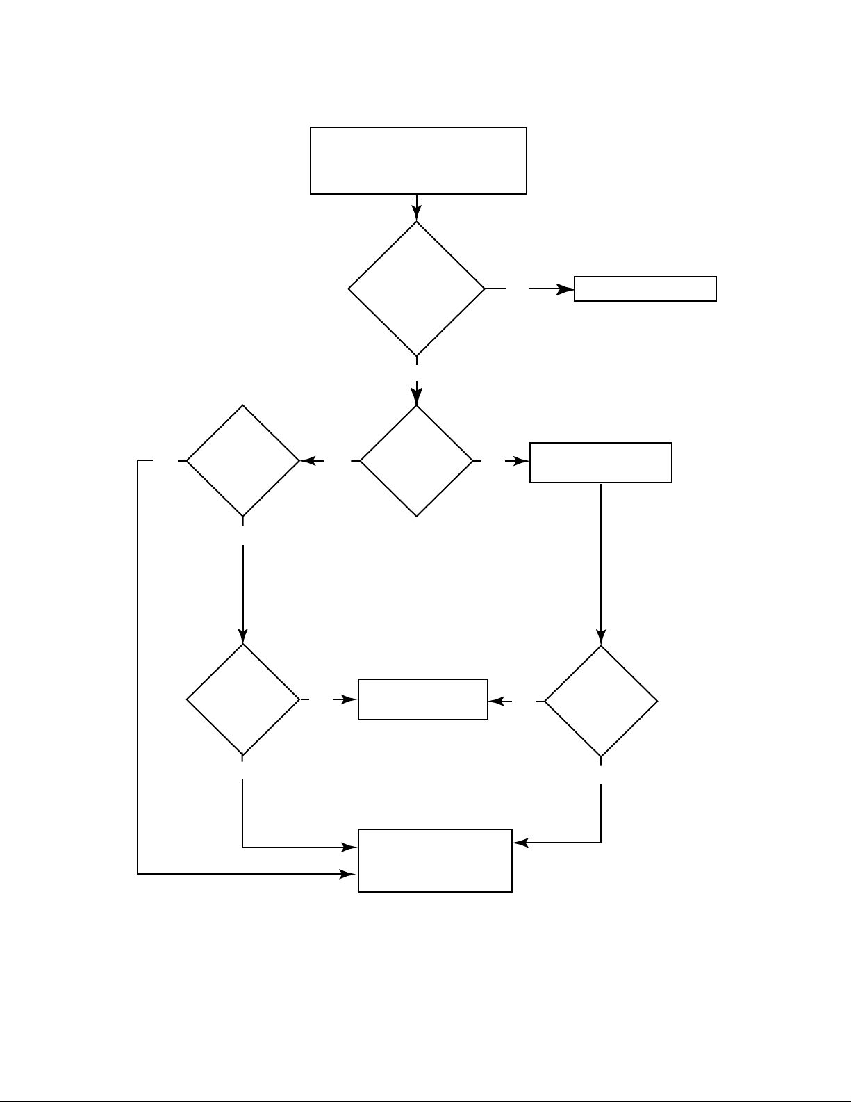
Chart #3: Temperature Indicator Checks
AC and Gas Indicators are ON
Temperature Indicator Either
ON or Blinks Once
When Torch is Activated
Temp Indicator
ON Steady
When Torch is
Activated
Yes
No
(blinks once)
Proceed to Chart #4
No
Fan
Operating?
Yes
Temperature
Indicator Still
ON?
Yes
No
No
Duty Cycle
Exceeded?
Use Proper
Operating Procedures
Replace Power Supply
Assembly
Yes
Allow Power Supply
No
Temperature
Indicator ON?
To Cool
Yes
SERVICE 5-6 Manual 0-2879
Page 31

Chart #4: Shorted Torch or Resistor (R3) Checks
AC and Gas Indicators are ON
DC Indicator Blinks or Momentary ON
When Torch is Activated
Check Pilot Wire
per Section 5.08-E
Pilot Wire
Check Correct?
Yes
Check Resistor (R3) Assembly
per Section 5.08-F
Resistor R3
Check Okay?
Yes
Replace Power Supply
No
No
Replace
Leads Assembly
Replace Resistor (R3)
Assembly
per Section 5.09-P
Manual 0-2879 5-7 SERVICE
Page 32

Chart #5: Faulty Torch or Torch Switch Checks
A
AC and Gas Indicators are ON
DC Indicator OFF
When Torch is Activated
Check Torch And Leads
Assembly
Torch & Leads
Check Correct?
No
Replace Torch
B
AC Indicator ON
No GAS Flow When Torch
Check Torch Switch
per Section 5.08-H
is Activated
Compressor
operates
4 seconds at
power ON?
Yes
No
Check Troubleshooting
per Section 5.05-C
Yes
Replace Power Supply
Torch Switch
Check Correct?
Yes
Replace Power Supply
No
Replace Torch
SERVICE 5-8 Manual 0-2879
Page 33

Chart #6: Faulty Current Control
CURRENT Control Knob Turns Completely
Around And Doesn't Stop At Minimum Or
Maximum Positions
Check Shaft Of CURRENT
Control Is Not Loose Or
Broken From PC Board
Is Control
Shaft Okay?
Yes
Secure or Replace
CURRENT Control
Knob per Section 5.09-C
No
Replace Power Supply
Manual 0-2879 5-9 SERVICE
Page 34

5.08 Test Procedures
The checks in these test procedures are all made with the
main power disconnected.
WARNINGS
Disconnect primary power to the system at the
source before opening the Power Supply.
A. Opening Power Supply Enclosure
1. Left/ & Right Side Panel Removal
The Left and Right Side Panels are removed in the
same manner as follows:
a. Remove the six screws which secure the Side
Panel to unit.
b. Carefully (see NOTE) pull the Side Panel away
from the unit far enough to gain access to the
inside of the unit.
NOTE
There is a ground wire connection to the Side Panel
on the inside of the unit.
2. Top Panel Removal
NOTE
Torch Control
Connectors
Work Cable
Connection
A-03251
Pilot Wire
Connection
Figure 5-1 Wiring Connections
CAUTION
DO NOT overtorque the nuts on the terminals as
the PC Board may be damaged.
d. Disconnect the Pilot Wire from the stud ter-
minal on the Main PC Board.
The Right Side Panel must be removed first to provide internal access to the torch and work cable
connections.
a. Remove the Right Side Panel per paragraph
'A-1' above.
b. Remove the Current Knob per Section 5.09-C.
c. Disconnect the Torch Lead from the Torch
Block.
e. Disconnect the T orch Control Connectors from
the wiring harness connected to J3 on the Main
PC Board.
f. Disconnect the Work Cable from the terminal
stud on the Main PC Board.
g. Remove the four screws securing the T op Panel
to the Power Supply.
h. Carefully remove the Top Panel (see NOTE)
from the Power Supply . Be car eful not to damage the current control shaft.
NOTE
There is a ground wire connection to the Top Panel
on the inside of the Power Supply.
i. Disconnect the ground wire connection from
the Top Panel.
j. Place the Top Panel aside.
SERVICE 5-10 Manual 0-2879
Page 35

B. Checking Input Diode Bridge
Testing of diode modules requires a digital volt/ohm
meter that has a diode test scale or an analog VOM with
1X or X10 scale. Remember that even if the diode module checks good, it may still be bad. If in doubt, replace
the Power Supply.
1. Remove the Left Side Panel of the Power Supply
per paragraph A-1 above.
2. Locate the Input diode Bridge (outside edge of
Heatsink). Make a visual check of the Input Diode Bridge for damage.
A-02135
AC
AC
( )
( )
AC
Figure 5-3 Input Diode Diagram
(+)
AC
(+)
A-01274
A-00307
Input Diode
Location
Figure 5-2 Input Diode Location
3. Set digital volt/ohm meter to diode test scale.
4. Using the Figures for each test, check each diode
in the module. Each diode must be checked in
forward bias (plus to negative) and reverse bias
(negative to plus) direction.
5. Input Rectifier should be isolated for further testing. Label and disconnect wires attached to Input Rectifier .
6. Connect the volt/ohm meter positive lead to the
anode of the diode and the negative lead to the
cathode of the diode for forward bias testing. A
properly functioning diode will conduct in the forward bias direction and indicate between 0.3 to
0.9 volts.
7. Reverse the meter leads across the diode for reverse bias testing. A properly functioning diode
will block in the reverse bias direction and depending on the meter function will indicate an
open or "OL".
0.75
Forward Bias
Diode Conducting
Diode T est Symbol
Anode
Cathode
+
VR
COM
_
A
Figure 5-4 Testing Diode Forward Bias
8. For an analog meter, use the meter set on X1 or
X10 scale to measure the resistance of each diode
in both directions. The readings should differ by
at least a factor of 10. If they do not differ (either
high or low in both directions) then replace the
diode module.
9. If Input Rectifier tests out okay, r eplace leads.
Manual 0-2879 5-11 SERVICE
Page 36

10. If the diode has visible damage or is shorted, the
diode is faulty. Replace the Power Supply.
A-00306
OL
Reverse Bias
Diode Not Conducting
D. Checking Capacitor PC Board
1. Remove the Top Panel of the Power Supply per
paragraph A-2 above.
A-03252
Capacitor PC
Board
Cathode
Anode
+
VR
COM
_
A
Figure 5-5 Testing Diode Reverse Bias
C. Checking FET Assemblies
1. Remove the Top Panel of the Power Supply per
paragraph A-2 above.
2. Using an ohmmeter set on the Rx1 scale make
the following checks:
a. Measure from Capacitor PC Board (+) to Main
Transformer Wir e #3. If the meter indicates a
short the FET Assemblies are faulty.
b. Measure from Capacitor PC Board (-) to Main
Transformer Wir e #3. If the meter indicates a
short the FET Assemblies are faulty.
Figure 5-7 Capacitor PC Board Location
2. Using an ohmmeter set on the Rx1 scale make the
following check:
a. Measure from Capacitor PC Board (+) to (-)
terminals. The meter should increase in resistance as the capacitors charge. Reverse probes
and test again. Resistance should decrease and
then increase as the capacitor discharges and
charges. If meter shows short, open or does
not change, replace Capacitor PC Board.
Capacitor
PC Board
Wire #3
(+) T erminal
(-) T erminal
Capacitor
PC Board
(N) T erminal
A-03228
Wire #3
(+) T erminal
(-) T erminal
(N) T erminal
A-03228
Figure 5-8 Check At Capacitor PC Board
Figure 5-6 FET Assembly Check At Capacitor PC
Board
SERVICE 5-12 Manual 0-2879
Page 37

E. Checking Pilot Wire
1. Remove the Right Side Panel of the Power Supply per paragraph A-1 above.
2. Remove the Pilot Wire from the stud terminal on
the Main PC Board.
A-03253
Pilot Wire
Connection
A-03254
Resistor (R3)
Figure 5-10 Resistor R3 Location
3. Using an ohmmeter set on the Rx100 scale make
the following check:
Figure 5-9 Pilot Wire Connection
3. Using an ohmmeter set on the Rx1 scale make the
following checks:
a. Measure from the T orch Block and the end of
the Pilot Wire. The meter should indicate an
open.
b. Measure from Pilot Wir e to the torch tip. Meter
should indicate a short (less than 1 ohm).
• If either test is faulty, replace Torch & Leads
Assembly or repair Torch components per
Manual supplied with the Torch.
4. Reinstall the Pilot Wire back onto the stud terminal on the Main PC Board.
F. Checking Resistor R3 (11k ohms)
1. Remove the Right Side Panel of the Power Supply per paragraph A-1 above.
2. Using a pair of needle nose pliers, remove the red
wire from the terminal on Resistor R3.
a. Measure the Resistance of the Resistor R3. The
meter should indicate 11K ohms.
4. Reinstall the wire back onto the Resistor terminal.
5. Check that the other ends of both red and blue
wires are properly attached.
G. Checking Built-In Air Compressor Circuits
1. Remove the Top Panel of the Power Supply per
paragraph A-2 above.
2. Check the built-in Air Compr essor for a blockage.
a. Check if the Compressor is humming. If Com-
pressor is humming, the air flow may be
blocked.
Remove the inlet filter and output hose from
the Compressor. Check for a clogged or dirty
filter . Check for a blockage in the output hose,
Torch Leads, Torch Head or Torch Consumables.
Replace the filter or remove the blockage.
3. Check the Starting Capacitor (C1) for proper operation.
During the four seconds after the ON/OFF Switch
is turned ON make the following check:
Manual 0-2879 5-13 SERVICE
Page 38

T est for 208 or 230VAC between wires #19 and
#23 on TB1.
• If the voltage is present and the Compressor is humming, check the Starting Capacitor.
NOTE
Faulty Capacitors can be shorted, open or reduced
in capacitance.
Check the Starting Capacitor for a short, open or
reduced capacitance as follows:
• Check for shorted Capacitor
A shorted Capacitor may be found with an ohmmeter . Remove the leads fr om one of the Capacitor terminals then measure across the terminals.
If it reads a low resistance (less than a few thousand ohms) then it is shorted and should be replaced.
• Check for an open Capacitor or reduced capacitance
To check a Capacitor for an open or that has reduced capacitance requires a capacitance meter.
If a meter is not available, try substituting a good
Capacitor . If the compressor starts using the good
Capacitor , then the original Capacitor was faulty.
H. Checking T orch Switch
1. Remove the Right Side Panel of the Power Supply per paragraph A-1 above.
2. Disconnect the T orch Control Connectors fr om the
wiring harness connected to J3 on the Main PC
Board.
Torch Control
Connectors
J3
A-03255
Figure 5-11 Torch Control Connectors
4. Check the built-in Air Compressor for overheating.
a. If the unit has just been operated for an ex-
tended time, the Compressor may be overheated. W ait for the Compressor to cool down.
If the Compressor is not overheated, then
Compressor is defective.
5. Check the built-in Air Compressor for proper operating voltage.
a. During the four seconds after the ON/OFF
Switch is turned ON make the following
check:
T est for 208 or 230VAC between wires #19 and
#23 on TB1.
• If voltage is not present, check for 24 V AC
on Relay K3 coil from J2-3 to J2-4 on the
Main PC Board. The Relay controls the AC
voltage to the Compressor .
• If 24 VAC is present, Relay K3 is faulty.
• If 24 V AC is not present, check that J2 connector is plugged into the Main PC Board.
If J2 is connected properly, the Main PC
Board is faulty. Return the unit for service.
3. Using an ohmmeter set on the Rx1 scale make the
following checks:
a. Measure between the two Torch Contr ol Con-
nectors.
• The meter should indicate an open.
b. Measure between the two T orch Contr ol Con-
nectors while pressing and holding the Torch
Switch (see NOTE).
• The meter should indicate a short.
NOTE
The Shield Cup must be installed to complete the
circuit through the Parts-In-Place (PIP) contacts.
4. Reconnect the Torch Control Connectors to the
wiring harness from J3 on the Main PC Board.
SERVICE 5-14 Manual 0-2879
Page 39

5.09 Power Supply Component Replacement Procedures
Refer to Section 6 for replacement parts lists, parts orientation and ordering information.
WARNING
Disconnect primary power to the system before disassembling the torch, leads, or power supply.
A. Handle Replacement
1. Remove four bolts securing the Handle to the Rear
Panel of the Power Supply.
2. Install replacement Handle being careful not to
over tighten the bolts.
B. Filter Dryer Element Replacement
1. Locate the Filter Dryer Assembly on the Rear
Panel of the Power Supply.
2. Remove the metal bowl of the Filter Dryer Assembly by turning the bowl counterclockwise.
3. Remove the Filter Element Assembly from the
plastic bell by turning counter-clockwise.
4. Disassemble the Filter Element Assembly and remove the Filter Element.
C. Current Control Knob Replacement
1. Using a small blade screwdriver , loosen the scr ew
securing the knob to the CURRENT Control adjustment shaft.
2. Turn the CURRENT Control adjustment shaft
fully clockwise. This will represent the maximum
position.
3. Slide the replacement knob onto the shaft.
4. Turn the knob so that the line on the knob points
towards the wide end of the current control symbol (maximum position).
5. Tighten the screw in the knob to secure the knob
to the shaft.
6. Turn the knob fully counterclockwise. The line
on the knob should line up with beginning of the
CURRENT Control adjustment symbol (minimum position).
7. Adjust the knob as required to align the minimum
and maximum reference points.
D. Left and Right Side Panel Replacement
The Left and Right Side Panels are replaced in the same
manner . Use caution when r emoving the panels as ther e
is a ground wire connected to the inside of each panel.
1. Remove the six screws securing the Side Panel to
the unit.
2. Remove the panel from the Power Supply a short
distance (see note).
A-02136
Filter Dryer
Element
Plastic Bell
Figure 5-12 Filter Dryer Assembly
5. Install the replacement Filter Element by reversing the above steps.
NOTE
There is a ground wire attached to the inside of
both side panels.
3. Remove the nut securing the ground wire to the
Side Panel and set the panel aside.
4. To reinstall the replacement Side Panel do the following:
a. Reconnect the ground wire to the panel.
b. Place the panel onto the frame.
c. Install all the screws to secure the panel.
Manual 0-2879 5-15 SERVICE
Page 40

E. Top Panel Replacement
1. Remove the Current Knob per paragraph 'C'
above.
2. Remove the Right Side Panel (see NOTE) per Section 5.08-A-1.
NOTE
The Right Side Panel must be removed to provide
internal access to the torch and work cable connections.
3. Disconnect the torch lead from the torch block.
Torch Control
Connectors
8. Remove the Top Panel from the Power Supply a
short distance (see note) being careful not to damage the current control shaft.
NOTE
There is a ground wire attached to the inside of the
Top Panel.
9. Remove the nut securing the ground wire to the
Top Panel and set the panel aside.
10. To reinstall the replacement Top Panel do the following:
a. Reconnect the ground wire to the panel.
b. Place the panel onto the frame.
c. Install all the screws to secure the panel.
F. Fuse (F1) Replacement
1. Remove the Left Side Panel per Section 5.08-A-1.
2. Locate the Fuse inside the unit on the left side of
the Main PC Board.
3. Using a pair of needle nose pliers, carefully remove the Fuse.
Work Cable
Connection
A-03251
Pilot Wire
Connection
Figure 5-13 Wiring Connections
CAUTION
DO NOT overtorque the nuts on the terminals as
the Main PC Board may be damaged.
4. Disconnect the Pilot Wire from the stud terminal
on the Main PC Board.
5. Disconnect the T orch Control Connectors fr om the
wiring harness connected to J3 on the Main PC
Board.
6. Disconnect the W ork Cable from the terminal stud
on the Main PC Board.
4. Replace the Fuse with the proper rating and type.
5. Reinstall the Left Side Panel.
G. AC Power ON/OFF Switch (SW1)
Replacement
The replacement procedure is the same for all AC Power
Switches. The location of the Switch and wiring to the
Switch are different.
1. Remove the Left Side Panel per Section 5.08-A-1.
2. Label and remove the four wires connected to the
Switch.
3. Note the orientation of the Switch and remove the
two nuts securing the Switch to the inside of the
panel.
4. Remove the Switch from the Power Supply.
7. Remove the four screws securing Top Panel to
Power Supply .
SERVICE 5-16 Manual 0-2879
Page 41

5. Install the replacement Switch by reversing the
above steps. Depending on the unit, connect the
wires to the Switch per one of the following Figures:
• Domestic Units
H. Relay (K3) Replacement
1. Remove the Left Side Panel per Section 5.08-A-1.
2. Locate the Relay near the Starting Capacitor.
3. Note the orientation of the Relay to the base of
the unit.
ON/OFF Switch
Assembly
Black
Wire #3
Black
Wire #19
A-02137
• CE and Australia Units
Input Power Cable
(White Wire)
Input Power Cable
(Black Wire)
Input Power Cable
(Ground Wire)
A-02574
4. Remove the two screws securing the Relay to the
base of the unit.
5. Note all wiring connections to the Relay.
Red #23
Red #3
Blue #3
Blue #12
Blue #11
A-02608
Capacitor
Figure 5-15 Relay Wiring
#3
#19
#S1
#S2
Figure 5-14 ON/OFF Switch Connections
6. Remove all the connections from the Relay.
7. Install the replacement Relay by reversing the
above steps.
Manual 0-2879 5-17 SERVICE
Page 42

I. Input Power Cable Replacement
6. Pull the Input Power Cable from the unit.
Depending on the unit, remove the Input Power Cable
per one of the following procedures:
• Domestic Units
1. Remove the Left Side Panel per Section 5.08-A-1.
2. Disconnect the Input Power Cable wires from the
Power Supply at the ground stud and the
ON/OFF Switch.
3. Loosen the Strain Relief on the rear of the unit
and pull the Input Power Cable from the unit.
4. Install replacement Power Cable by reversing the
above steps. Connect the wires as shown in the
following Figure:
ON/OFF Switch
Assembly
Input Power Cable
(Black Wire)
Two Green Wires
with Tracers
Input Power Cable
(White Wire)
7. Install replacement Power Cable by reversing the
above steps. Connect the wires as shown in the
following Figure:
Filter
Cover
L2
L1
A-02572
EMC
Filter
GND
Input Power Cable
Figure 5-17 CE and Australia Units - Input Power
Cable Connections
Input Power Cable
(Green Wire)
A-02139
Ground Stud
Figure 5-16 Domestic Units - Input Power Cable
Connections
• CE and Australia Units
1. Loosen Strain Relief on the rear of the unit.
2. Remove six screws securing rear Filter Cover to
the EMC Filter box.
3. Slide the Filter Cover along the Input Power Cable
to gain access to the wiring connections.
4. Note and label the location of the Input Power
Cable wire connections.
J. Pressure Switch (PS1) Replacement
1. Remove the Right Side Panel per Section 5.08-A-1.
2. Disconnect the wires connected to the Pressure
Switch.
3. Remove the Pressure Switch Assembly from the
T ee Fitting.
4. Install the replacement Pressur e Switch by reversing the above steps (see NOTE).
NOTE
Apply a coating of thread sealant (Loctite #565 or
equivalent) to the threads of the replacement Pressure Switch prior to installing.
#7 Connector
Compressor
#6 Connector
Pressure Switch
Tee Fitting
1/8 NPT
5. Disconnect the Input Power Cable wires from the
terminals on the EMC Filter .
Air Intake Filter
A-02609
Figure 5-18 Pressure Switch Wiring Connections
SERVICE 5-18 Manual 0-2879
Page 43

K. Current Control Knob Guard(s)
Replacement
NOTE
The torch lead and work lead must be disconnected
to replace the Current Control Knob Guards.
1. Remove the Top Panel per Section 5.08-A-2.
2. Remove the nuts securing Current Control Knob
Guard(s) to the Top Panel.
3. Install the replacement Current Control Guard(s)
by reversing the above steps.
L. Work Cable and Clamp Replacement
1. Remove the Right Side Panel per Section 5.08-A-1.
2. Disconnect the Work Cable connection from the
Main PC Board.
3. Remove the W ork Cable Strain Relief from the Top
Panel and remove the cable from unit.
4. Install the replacement Work Cable by reversing
the above steps.
M. Capacitor PC Board Replacement
1. Remove the Top Panel per Section 5.08-A-2.
2. For improved access to the Capacitor PC Board
do the following:
a. Remove the two nuts and washers securing
the Center Divider to the Power Supply Base.
b. Slide the Center Divider towards the Com-
pressor.
3. Remove the black pad located on the Capacitors.
Mounting Standoffs
Capacitor
PC Board
Wire #3
(N)
(-) T erminal
(+) T erminal
A-03256
Figure 5-19 Capacitor PC Board Connections
5. Remove the Capacitor PC Board from the unit.
6. Install the replacement Capacitor PC Board by r eversing the above steps. Torque the nuts on terminals (+), (-), and (N) to 15 inch-lbs (1.7 Nm).
CAUTION
4. The Capacitor PC Board is secured to the Main
PC Board by two methods.
a. Remove the nuts and star washers located at
terminals (+), (-), and (N).
b. Locate the three plastic mounting standoffs.
T wo standof fs are located along the top edge
of the PC Board and a third is located near the
center of the PC Board. To remove the Ca-
DO NOT over torque the nuts on the terminals as
the PC Board may be damaged.
N. Pilot Resistor (R1) Replacement Procedure
1. Remove the Right Side Panel per Section 5.08-A-1.
2. Locate the Pilot Resistor near the outside edge of
the unit, below the Main PC Board Assembly.
NOTE
pacitor PC Board from the standof fs, squeeze
the tab on the mounting standoff while pulling up on the PC Board.
There are two resistors mounted in this ar ea, Pilot
Resistor (15 ohms) and Damping Resistor (30
ohms). The Pilot Resistor is mounted on the bottom.
Manual 0-2879 5-19 SERVICE
Page 44
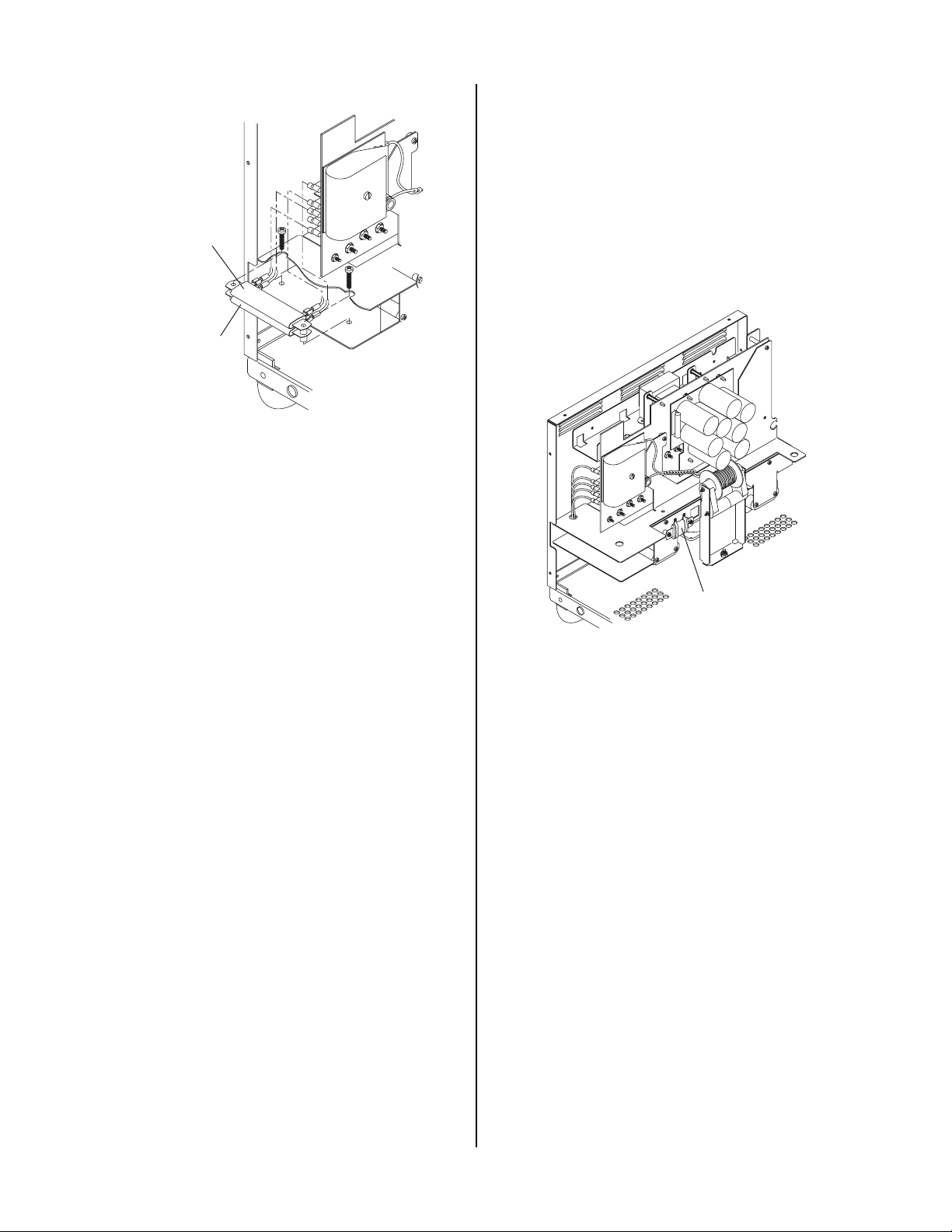
Damping Resistor
Pilot Resistor
(R1)
A-03257
Figure 5-20 Pilot Resistor (R1) Replacement
3. Using a phillips screwdriver, remove the two
screws securing the Pilot and Damping Resistors
to the internal frame.
O. Resistor (R3) Replacement
1. Remove the Right Side Panel per Section 5.08-A-1.
2. Remove the two screws securing the Center Divider to the Power Supply Base.
3. Lift the vertical Center Divider up and out towards the Compressor to gain access to the Resistor. Locate Resistor (R3), as shown in the figure below.
A-03254
4. Pull the Pilot Resistor out far enough to gain access to the two wiring connections.
5. Note the location of the two wires connected to
the Pilot Resistor and disconnect the wires.
6. Install the replacement Pilot Resistor by reversing the above steps.
Resistor (R3)
Figure 5-21 Resistor (R3) Location
4. Note the wiring connections to the Resistor.
5. Remove the wires from the terminals on the Resistor.
6. Remove the Resistor from the Power Supply .
7. Install the replacement Resistor by reversing the
above steps.
P. Starting Capacitor (C1) Replacement
1. Remove Top Panel per Section 5.08-A-2.
2. Locate the Starting Capacitor attached to the base
of the Power Supply, near the Compressor.
3. Note all the wiring connections to the Starting
Capacitor.
4. Remove all the wires connected to the starting
capacitor . Remove any tie wraps if necessary.
5. Loosen the Clamp at the base of the Starting Capacitor .
SERVICE 5-20 Manual 0-2879
Page 45

6. Remove the Starting Capacitor from the Power
Supply.
7. Install the replacement Starting Capacitor by reversing the above steps. Reconnect the wires as
follows:
Compressor Side
4. Disconnect the two T orch Contr ol Connectors and
the Pilot Wir e from the Main PC Board Assembly
connectors.
Torch Control
Connectors
Plain Wire
Striped Wire
A-02575
Figure 5-22 Starting Capacitor Wiring
5.10 Torch and Leads Replacement
Procedure
1. Remove Right Side Panel per Section 5.08-A-1.
2. Locate the Torch Block area as shown in the following Figure.
A-03238
Pilot Wire
A-03239
Connection
Figure 5-24 Torch Wiring Connections
NOTE
All wires are outside the protective insulating sheet.
5. Remove the nylon screw holding the protective
insulating sheet to the Torch Block.
Torch Block
Area
Nylon Screw
Removal
Figure 5-23 Torch Block Area Location
3. Loosen the torch lead strain relief nut inside the
A-03247
Figure 5-25 Nylon Screw Removal
Top Panel. Do not remove the strain relief from
the leads. Replacement torch leads are provided
with strain reliefs.
Manual 0-2879 5-21 SERVICE
Page 46

6. Loosen the torch lead fitting from the brass torch
block. This fitting must be removed from the
T orch Lead and installed on the replacement lead.
CAUTION
Be sure all wires are outside the pr otective insulating sheet as noted above when it is reinstalled. High
voltage is present on the torch negative lead.
Torch Negative
Lead
Torch Lead
Fitting
Bulkhead
A-03240
Figure 5-26 Torch Lead Connection
7. Install the replacement Torch and Leads Assembly by reversing the above steps.
SERVICE 5-22 Manual 0-2879
Page 47

SECTION 6:
PARTS LISTS
6.01 Introduction
A. Parts List Breakdown
The parts list provides a breakdown of all replaceable
components. Power Supply and T orch Assembly are field
serviceable, so a complete breakdown of parts is provided.
The parts lists are arranged as follows:
Section 6.03 Power Supply Replacement Parts
Section 6.04 Rear Panel Replacement Parts
Section 6.05 Complete Assembly Replacements
NOTE
Parts listed without item numbers are not illustrated, but may be ordered by the catalog numbers
shown.
B. Returns
If a product must be returned for service, contact your
authorized distributor . Materials returned without proper
authorization will not be accepted.
6.02 Ordering Information
Order replacement parts by catalog number and complete
description of the part or assembly, as listed in the description column of the Parts List. Also include the model
and serial number of the torch. Address all inquiries to
your authorized distributor .
Manual 0-2879 6-1 P A RTS LISTS
Page 48

6.03 Power Supply Replacement Parts
Item # Qty Description Catalog #
1 1 Left Side Panel with Labels 9-7707
2 1 Right Side Panel with Labels 9-7708
3 1 Top Panel with Labels 9-7709
4 Rear Panel with Labels - Refer to Section 6.04 for Replacement Parts
5 1 Front Panel with Labels 9-7706
6 1 Current Control Knob Assy 9-7710
7 2 Current Control Knob Guards 9-7717
8 1 Pressure Switch - 35 psi PS1 9-1044
9 1 Capacitor PC Board Assembly 9-4607
10 1 Air Compressor, 200-230VAC, 50/60Hz M1 9-7720
11 2 Wheel, 6" diameter 9-4283
12 1 Axle 9-4282
13 2 Retaining Ring, 1/2 in. Dia Shaft (Axle) 9-5539
14 4 Flat Washer - 1/2 in. (13 mm) I.D. (Axle) See Note
15 1 Air Intake Filter Kit - Replacement Filter Pads (One of each Type) 9-7716
16 1 Foot 9-4284
17 1 Relay, SPDT, 15A, 220V 24AC Coil K3 9-7914
18 1 Starting Capacitor C1 9-7722
19 1 Fuse, 1/2 Amp, 250V F1 9-7711
20 1 Resistor, 1 1K ohms 30W R3 9-7701
21 1 Pilot Resistor, 15 ohms 55W R1 9-6323
The following parts are not shown:
1 Work Cable 20 ft (6.0 m) with Clamp 9-6596
NOTE: Hardware can be purchased locally.
PARTS LISTS 6-2 Manual 0-2879
Page 49

6
3
7
2
4
8
15
10
18
17
1
16
12
5
13
9
14
11
20
A-03230
19
21
Manual 0-2879 6-3 P A RTS LISTS
Page 50

6.04 Rear Panel Replacement Parts
Item # Qty Description Catalog #
1 1 Rear Panel with Labels
Domestic Units ------
CE and Australian Units 9-7705
2 1 Handle 9-7712
3 1 ON/OFF Switch SW1 8-4248
4 1 Filter Dryer Replacement Kit 9-6599
1 Filter Dryer Element 9-7718
5 1 Fan 9-1033
6 1 EMC Filter (For CE and Australian Units Only) 9-7950
The following parts are not shown:
1 Input Power Cable
Domestic Units - 10 ft (3.0 m) with 50A Plug 9-7714
CE Units - 9.5 ft (2.9 m) Without Plug 9-7953
Australian Units - 9.5 ft (2.9 m) Without Plug 9-7951
PARTS LISTS 6-4 Manual 0-2879
Page 51

Domestic Units
2
4
1
5
A-03264
CE & Australia Units
3
4
2
6
1
3
A-03265
Manual 0-2879 6-5 P A RTS LISTS
5
Page 52

6.05 Complete Assembly Replacement
Description Catalog #
Domestic System includes:
Power Supply with Built-In Air Compressor, Torch with Leads, Spare Parts Kit, Input Power Cable With Plug
and Work Cable With Clamp.
70° Torch with 20 ft (6.1 m) Leads 1-3800
90° Torch with 20 ft (6.1 m) Leads 1-3801
CE and Australian Systems includes:
CE Power Supply with Built-In Air Compressor, Torch with Leads, Spar e Parts Kit, Input Power Cable Without Plug and Work Cable With Clamp.
70° Torch with 20 ft (6.1 m) Leads 1-8800
90° Torch with 20 ft (6.1 m) Leads 1-8801
Power Supply Only
Domestic Units 3-3800
CE and Australian Units 3-8801
Hand Torches with Two Piece Standard Handle
PCH-42R RPT 70° Hand Torch, 20 ft (6.1 m) Leads 7-4226
PCH-42R RPT 90° Hand Torch, 20 ft (6.1 m) Leads 7-4227
Torch Spare Parts Kit Includes: 5-4204
Qty Description
5 T ip, Air
5 Electrode, 40A SureLok
1 Distributor, Gas
1 Shield Cup, Standard
1 Box, Utility
1 Adhesive Hang Tab
1 Label, Spare Parts Kit
PARTS LISTS 6-6 Manual 0-2879
Page 53

APPENDIX 1: SEQUENCE OF OPERATION BLOCK
DIAGRAM
ACTION
Plug in
Power Cord
RESULT
Power to system.
ACTION
Protect eyes and
activate torch
RESULT
Compressor starts and
Gas flows
GAS indicator ON
After gas pre-flow:
DC indicator on.
Power supply enabled.
Pilot arc established
ACTION
ON/OFF switch
to ON.
RESULT
AC Indicator flashes for
3 seconds then stays on.
Air Compressor runs
for 3 seconds then off.
Fan on.
PILOT ARC
ACTION
Torch moved away
from work (while
still activated).
RESULT
Main arc stops.
Pilot arc auto-
matically restarts.
ACTION
Torch moved within
transfer distance of
workpiece.
RESULT
Main arc transfer.
ACTION
Torch deactivated by torch
switch release.
RESULT
Main arc stops. Pilot stops.
(Power supply enable signal removed.)
Compressor stops. Gas flow stops.
NOTE - If torch is activated during
post-flow, pilot arc will immediately restart.
If torch is within transfer distance (1/8 in) of
workpiece, main arc will transfer.
DC indicator off.
After post-flow:
GAS indicator OFF.
ACTION
ON/OFF switch
to OFF
RESULT
All indicators off.
Power supply
fan off.
Pilot arc off.
DC indicator still on.
ACTION
Unplug
Power Cord
RESULT
No power to system.
A-02151
Manual 0-2879 A-1 APPENDIX
Page 54

APPENDIX 2: ROUTINE MAINTENANCE SCHEDULE
This schedule applies to all types of non-liquid cooled plasma cutting systems. Some systems will not have all the
parts listed and those checks need not be performed.
NOTE
The actual frequency of maintenance may need to be adjusted according to the operating environment.
Daily Operational Checks or Every Six Cutting Hours:
1. Check torch consumable parts, replace if damaged or worn.
2. Inspect torch for any cracks or exposed wires, replace if necessary.
3. Check plasma and secondary supply and pressure/flow.
4. Purge plasma gas line to remove any moisture build-up.
5. Inspect input power cable for damage or exposed wires, replace if necessary.
Weekly or Every 30 Cutting Hours:
1. Check fan for proper operation and adequate air flow.
2. Blow or vacuum dust and dirt out of the entire machine.
CAUTION
Do not blow air into the power supply during cleaning. Blowing air into the unit can cause metal particles to
interfere with sensitive electrical components and cause damage to the unit.
Six Months or Every 720 Cutting Hours:
1. Check the in-line air filter(s), clean or replace as required
2. Check cables and hoses for leaks or cracks, replace if necessary .
3. Check all contactor points for severe arcing or pits, replace if necessary.
APPENDIX A-2 Manual 0-2879
Page 55

APPENDIX 3: RECOMMENDED CUTTING SPEEDS
NOTE
Cutting speeds are for use with PCH-42 RPT Torch.
Drag-Gun 38 Cutting Speeds (Air Pressure @ 50 psi for all settings)
Material Thickness
26 Gauge 250 310 385 drag-1/8"
20 Gauge 125 245 310 drag-1/8"
Mild Steel
24 Gauge 150 310 385 drag-1/8"
Stainless Steel
24 gauge 100 290 360 drag-1/8"
Galvanized Steel
Aluminum
NR = Not Recommended
20 gauge 75 228 310 drag-1/8"
18 gauge 65 172 233 drag-1/8"
16 gauge 45 140 203 drag-1/8"
Recommended
Cut
Speed @ 20 Amps
1/16" 85 140 208 drag-1/8"
1/8 " 25 55 85 drag-1/ 8"
3/16 " 15 30 55 drag-1/16"
1/4 " 8 16 27 drag-1/16"
3/8 " NR 10 14 drag-1/16"
1/16" 40 80 115 drag-1/8"
1/8 " 25 44 70 drag-1/ 8"
3/16 " 10 19 27 drag-1/16"
1/4 " NR 14 20 drag-1/16"
1/16 " 150 223 280 drag-1/8"
3/32 " 25 105 172 drag-1/8"
1/8 " 10 60 85 drag-1/ 8"
3/16 " NR 20 30 drag-1/ 8"
Recommended
Cut
Speed @ 29
Amps
Maxi mu m C u t
Speed @29
Amps
Standoff
Manual 0-2879 A-3 APPENDIX
Page 56

APPENDIX 4: NON-CE SYSTEM SCHEMATIC
A-02201
APPENDIX A-4 Manual 0-2879
Page 57

NOTE
Refer to Appendix 5 for CE & Australia Power Supplies.
A-02201
Manual 0-2879 A-5 APPENDIX
Page 58

APPENDIX 5: CE & AUSTRALIA SYSTEM SCHEMATIC
A-02576
APPENDIX A-6 Manual 0-2879
Page 59

NOTE
Refer to Appendix 4 for all other Power Supplies.
A-02576
Manual 0-2879 A-7 APPENDIX
Page 60

 Loading...