

Page 1

C-35C
®
CUTSKILL
PLASMA CUTTING
SYSTEM
Service Manual
Art # A-09400
Rev. AB Date: November 17, 2009 Manual 0-4745
Operating Features:
PLASMA
Page 2

Page 3

WARNINGS
Read and understand this entire Manual and your employer’s safety practices before installing,
operating, or servicing the equipment.
While the information contained in this Manual represents the Manufacturer's best judgement,
the Manufacturer assumes no liability for its use.
Plasma Cutting Power Supply
CutSkill
®
PCH-42
Service Manual Number 0-4745
Covered under U.S. Patents.
Published by:
Thermadyne Corporation
82 Benning Street
West Lebanon, New Hampshire, USA 03784
(603) 298-5711
www.thermal-dynamics.com
©Copyright 2006, 2007, 2008, 2009 by
Thermal Dynamics Corporation
All rights reserved.
Reproduction of this work, in whole or in part, without written permission of the publisher is prohibited.
The publisher does not assume and hereby disclaims any liability to any party for any loss or damage
caused by any error or omission in this Manual, whether such error results from negligence, accident, or
any other cause.
Printed in the United States of America
Publication Date: November
17, 2009
Record the following information for Warranty purposes:
Where Purchased:____________________________________
Purchase Date:_______________________________________
Power Supply Serial #:________________________________
Torch Serial #:________________________________________
Page 4

Page 5

TABLE OF CONTENTS
SECTION 1:
GENERAL INFORMATION ................................................................................................ 1-1
1.01 Notes, Cautions and Warnings ...................................................................... 1-1
1.02 Important Safety Precautions ....................................................................... 1-1
1.03 Publications .................................................................................................. 1-2
1.04 Declaration of Conformity ............................................................................. 1-4
1.05 Statement of Warranty .................................................................................. 1-5
SECTION 2.0
INTRODUCTION .............................................................................................................. 2-1
2.01 INTRODUCTION .......................................................................................... 2-1
2.02 GENERAL SPECIFICATION ......................................................................... 2-1
2.03 Features ....................................................................................................... 2-1
2.04 Torch Specifications ..................................................................................... 2-2
2.05 System Contents .......................................................................................... 2-2
2.06 Transporting Methods ................................................................................... 2-2
SECTION 3.0
INSTALLATION ................................................................................................................. 3-1
3.01 Site Selection ............................................................................................... 3-1
3.02 Electrical Input Connections ......................................................................... 3-1
3.03 Torch ............................................................................................................ 3-1
SECTION 4.0
OPERATION ...................................................................................................................... 4-1
4.01 Front Control Panel ....................................................................................... 4-1
4.02 Preparations For Operating ........................................................................... 4-2
SECTION 5: MAINTENANCE .................................................................................................... 5-1
5.01 General Maintenance .................................................................................... 5-1
SECTION 6:
TROUBLESHOOTING ....................................................................................................... 6-1
6.01 Normal Setup and Operation ........................................................................ 6-1
6.02 Basic Trouble Shooting Guide ....................................................................... 6-2
6.03 Control PCB Indicators ................................................................................. 6-3
6.04 Open Circuit Voltage Check .......................................................................... 6-4
6.05 Detailed Fault Finding / Error Indicators ........................................................ 6-5
6.06 Torch Tests ................................................................................................... 6-9
SECTION 7:
PARTS LIST ...................................................................................................................... 7-1
7.01 Parts List Power Supply ................................................................................ 7-2
7.02 Replacement Hand Torch Parts With Ergonomic Handle ................................ 7-6
Page 6

TABLE OF CONTENTS (Con't)
Appendix 1: Operating Sequence, Block Diagram ..................................................................... A-1
Appendix 2: Torch Connection ................................................................................................... A-2
Appendix 3: Microchip Pin-Out .................................................................................................. A-3
Appendix 4: System Schematic 230V CE ................................................................................. A-4
Appendix 5: System Schematic 230V ....................................................................................... A-6
GLOBAL CUSTOMER SERVICE CONTACT INFORMATION .............................. Inside Rear Cover
Page 7

SECTION 1:
!
GENERAL INFORMATION
1.01 Notes, Cautions and Warnings
Throughout this manual, notes, cautions, and warnings are used to
highlight important information. These highlights are categorized as
follows:
NOTE
An operation, procedure, or background information
which requires additional emphasis or is helpful in efficient operation of the system.
CAUTION
A procedure which, if not properly followed, may cause
damage to the equipment.
WARNING
A procedure which, if not properly followed, may cause
injury to the operator or others in the operating area.
1.02 Important Safety Precautions
• Use an air-supplied respirator if ventilation is not adequate to
remove all fumes and gases.
• The kinds of fumes and gases from the plasma arc depend on the
kind of metal being used, coatings on the metal, and the different
processes. You must be very careful when cutting or welding
any metals which may contain one or more of the following:
Antimony Chromium Mercury
Arsenic Cobalt Nickel
Barium Copper Selenium
Beryllium Lead Silver
Cadmium Manganese Vanadium
• Always read the Material Safety Data Sheets (MSDS) that should
be supplied with the material you are using. These MSDSs will
give you the information regarding the kind and amount of fumes
and gases that may be danger
•For information on how to test for fumes and gases in your
workplace, refer to item 1 in Subsection 1.03, Publications in
this manual.
• Use special equipment, such as water or down draft cutting
tables, to capture fumes and gases.
• Do not use the plasma torch in an area where combustible or
explosive gases or materials are located.
• Phosgene, a toxic gas, is generated from the vapors of chlorinated solvents and cleansers. Remove all sources of these vapors.
• This product, when used for welding or cutting, produces fumes
or gases which contain chemicals known to the State of California to cause birth defects and, in some cases, cancer. (California
Health & Safety Code Sec. 25249.5 et seq.)
ous to your health.
WARNINGS
OPERATION AND MAINTENANCE OF PLASMA ARC
EQUIPMENT CAN BE DANGEROUS AND HAZARDOUS
TO YOUR HEALTH.
Plasma arc cutting produces intense electric and magnetic emissions that may interfere with the proper function of cardiac pacemakers, hearing aids, or other electronic health equipment. Persons who work near plasma
arc cutting applications should consult their medical health
professional and the manufacturer of the health equipment to determine whether a hazard exists.
To prevent possible injury, read, understand and follow
all warnings, safety precautions and instructions before
using the equipment. Call 1-603-298-5711 or your local
distributor if you have any questions.
GASES AND FUMES
Gases and fumes produced during the plasma cutting process can be
dangerous and hazardous to your health.
• Keep all fumes and gases from the breathing area. Keep your
head out of the welding fume plume.
ELECTRIC SHOCK
Electric Shock can injure or kill. The plasma arc process uses and
produces high voltage electrical energy. This electric energy can cause
severe or fatal shock to the operator or others in the workplace.
• Never touch any parts that are electrically “live” or “hot.”
• Wear dry gloves and clothing. Insulate yourself from the work
piece or other parts of the welding circuit.
• Repair or replace all worn or damaged parts.
• Extra care must be taken when the workplace is moist or damp.
• Install and maintain equipment according to NEC code, refer to
item 9 in Subsection 1.03, Publications.
• Disconnect power
pairs.
• Read and follow all the instructions in the Operating Manual.
FIRE AND EXPLOSION
Fire and explosion can be caused by hot slag, sparks, or the plasma arc.
• Be sure there is no combustible or flammable material in the
workplace. Any material that cannot be removed must be protected.
• Ventilate all flammable or explosive vapors from the workplace.
• Do not cut or weld on containers that may have held combustibles.
source before performing any service or re-
Manual 0-4745 1-1 GENERAL INFORMATION
Page 8

•Provide a fire watch when working in an area where fire hazards
may exist.
• Hydrogen gas may be formed and trapped under aluminum
workpieces when they are cut underwater or while using a water
table. DO NOT cut aluminum alloys underwater or on a water
table unless the hydrogen gas can be eliminated or dissipated.
Trapped hydrogen gas that is ignited will cause an explosion.
1.03 Publications
Refer to the following standards or their latest revisions for more infor-
mation:
1. OSHA, SAFETY AND HEALTH STANDARDS, 29CFR 1910,
obtainable from the Superintendent of Documents, U.S.
Government Printing Office, Washington, D.C. 20402
NOISE
Noise can cause permanent hearing loss. Plasma arc processes can
cause noise levels to exceed safe limits. You must protect your ears
from loud noise to prevent permanent loss of hearing.
•To protect your hearing from loud noise, wear protective ear
plugs and/or ear muffs. Protect others in the workplace.
• Noise levels should be measured to be sure the decibels (sound)
do not exceed safe levels.
•For information on how to test for noise, see item 1 in Subsec-
tion 1.03, Publications, in this manual.
PLASMA ARC RAYS
Plasma Arc Rays can injure your eyes and burn your skin. The plasma
arc process produces very bright ultra violet and infra red light. These
arc rays will damage your eyes and burn your skin if you are not
properly protected.
•To protect your eyes, always wear a welding helmet or shield.
Also always wear safety glasses with side shields, goggles or
other protective eye wear.
• Wear welding gloves and suitable clothing to protect your skin
from the arc rays and sparks.
• Keep helmet and safety glasses in good condition. Replace
lenses when cracked, chipped or dirty.
•Protect others in the work ar
booths, screens or shields.
• Use the shade of lens as suggested in the following per ANSI/
ASC Z49.1:
Arc Current Shade No. Shade No.
Less Than 300* 8 9
300 - 400* 9 12
400 - 800* 10 14
* These values apply where the actual arc is clearly seen.
Experience has shown that lighter filters may be used
when the arc is hidden by the workpiece.
LEAD WARNING
This product contains chemicals, including lead, or otherwise produces chemicals known to the State of California to cause cancer, birth
defects and other reproductive harm. Wash hands after handling.
(California Health & Safety Code § 25249.5 et seq.)
ea from the arc rays. Use protective
Minimum Protective Suggested
2. ANSI Standard Z49.1, SAFETY IN WELDING AND CUTTING,
obtainable from the American Welding Society, 550 N.W.
LeJeune Rd, Miami, FL 33126
3. NIOSH, SAFETY AND HEALTH IN ARC WELDING AND GAS
WELDING AND CUTTING, obtainable from the Superintendent of Documents, U.S. Government Printing Office, Washington, D.C. 20402
4. ANSI Standard Z87.1, SAFE PRACTICES FOR OCCUPATION
AND EDUCATIONAL EYE AND FACE PROTECTION, obtainable from American National Standards Institute, 1430
Broadway, New York, NY 10018
5. ANSI Standard Z41.1, STANDARD FOR MEN’S SAFETY-TOE
FOOTWEAR, obtainable from the American National Standards Institute, 1430 Broadway, New York, NY 10018
6. ANSI Standard Z49.2, FIRE PREVENTION IN THE USE OF
CUTTING AND WELDING PROCESSES, obtainable from
American National Standards Institute, 1430 Broadway,
New York, NY 10018
7. AWS Standard A6.0, WELDING AND CUTTING CONTAINERS WHICH HAVE HELD COMBUSTIBLES, obtainable from
American Welding Society, 550 N.W. LeJeune Rd, Miami,
FL 33126
8. NFPA Standard 51, OXYGEN-FUEL GAS SYSTEMS FOR
WELDING, CUTTING AND ALLIED PROCESSES, obtainable
from the National Fire Protection Association, Batterymarch
Park, Quincy, MA 02269
9. NFPA Standard 70, NATIONAL ELECTRICAL CODE, obtainable from the National Fir e Pr otection Association,
Batterymarch Park, Quincy, MA 02269
10. NFPA Standard 51B, CUTTING AND WELDING PROCESSES,
obtainable from the National Fire Protection Association,
Batterymarch Park, Quincy, MA 02269
11. CGA Pamphlet P-1, SAFE HANDLING OF COMPRESSED
GASES IN CYLINDERS, obtainable from the Compressed
Gas Association, 1235 Jefferson Davis Highway, Suite 501,
Arlington, VA 22202
12. CSA Standard W117.2, CODE FOR SAFETY IN WELDING
AND CUTTING, obtainable from the Canadian Standards
Association, Standards Sales, 178 Rexdale Boulevard,
Rexdale, Ontario, Canada M9W 1R3
13. NWSA booklet, WELDING SAFETY BIBLIOGRAPHY obtainable from the National Welding Supply Association, 1900
Arch Street, Philadelphia, PA 19103
14. American Welding Society Standard AWSF4.1, RECOMMENDED SAFE PRACTICES FOR THE PREPARATION FOR
WELDING AND CUTTING OF CONTAINERS AND PIPING
GENERAL INFORMATION 1-2 Manual 0-4745
Page 9

THAT HAVE HELD HAZARDOUS SUBSTANCES, obtainable
from the American Welding Society, 550 N.W. LeJeune Rd,
Miami, FL 33126
15. ANSI Standard Z88.2, PRACTICE FOR RESPIRATORY PROTECTION, obtainable from American National Standards
Institute, 1430 Broadway, New York, NY 10018
• Montez et maintenez le matériel conformément au Code électrique
national des Etats-Unis. (Voir la page
• Débranchez l’alimentation électrique avant tout travail d’entretien
ou de réparation.
• Lisez et respectez toutes les consignes du Manuel de consignes.
5,
article 9.)
Manual 0-4745 1-3 GENERAL INFORMATION
Page 10

1.04 Declaration of Conformity
Manufacturer : Ther mal Dynamics Cor poration
Address: 82 Benning Str eet
West Lebanon, New Hampshire 03784
USA
The equipment described in this manual confor ms to all applicable aspects and r egulations of the ‘Low Voltage Directive’
(European Council Dir ective 73/23/EEC as amended by Council Dir ective 93/68/EEC) and to the National legislation for the
enforcement of this Dir ective.
The equipment described in this manual confor ms to all applicable aspects and r egulations of the "EMC Directive" (European
Council Directive 89/336/EEC) and to the National legislation for the enforcement of this Directive.
Serial numbers are unique with each individual piece of equipment and details descr iption, parts used to manufactur e a unit and
date of manufacture.
National Standard and Technical Specifications
The product is designed and manufactur ed to a number of standards and technical r equirements. Among them ar e:
* CSA (Canadian Standards Association) standar d C22.2 numbe
* UL (Underwriter s Laboratory) rating 94VO flammability testing for all pr inted-circuit boar ds used.
* CENELEC EN50199 EMC Product Standar d for Arc Welding Equipment.
* ISO/IEC 60974-1 (BS 638-PT10) (EN 60 974-1) (EN50192) (EN50078) applicable to plasma cutting equipment and associated
accessories.
* For envir onments with increased hazard of electr ical shock, Power Supplies bearing the 'S' mark confor m to EN50192 when
used in conjunction with hand torches with exposed cutting tips, if equipped with pr operly installed standoff guides.
* Extensive product design ver ification is conducted at the manufacturing facility as par t of the routine design and manufactur-
ing process. This is to ensur e the product is safe, when used according to instr uctions in this manual and related industry
standards, and perfo
tured pr oduct meets or exceeds all design specifications.
Thermal Dynamics has been manufacturing products for more than 30 year s, and will continue to achieve excellence in our ar ea
of manufacture.
Manufacture r s responsible repr esentative: Steve Ward
rms as specified. Rigorous testing is incorpor ated into the manufacturing pr ocess to ensure the manufac-
Operations Director
Thermadyne Eur ope
Europa Building
Chorley N Industr ial Park
Chorley, Lancashire,
England PR6 7BX
r 60 for Arc welding equipment.
GENERAL INFORMATION 1-4 Manual 0-4745
Page 11

1.05 Statement of Warranty
LIMITED WARRANTY: Subject to the terms and conditions established below, Thermadyne® Corporation warrants to the original retail purchaser that
new Thermadyne CutSkill Series plasma cutting systems sold after the effective date of this warranty are free of defects in material and workmanship.
Should any failure to conform to this warranty appear within the applicable period stated below, Thermadyne Corporation shall, upon notification thereof
and substantiation that the product has been stored operated and maintained in accordance with Thermadyne’s specifications, instructions,
recommendations and recognized industry practice, correct such defects by suitable repair or replacement.
This warranty is exclusive and in lieu of any warranty of merchantability or fitness for a particular purpose.
Thermadyne will repair or replace, at its discretion, any warranted parts o
periods set out below. Thermadyne Corporation must be notified within 30 days of any failure, at which time Thermadyne Corporation will provide
instructions on the warranty procedures to be implemented.
Thermadyne Corporation will honor warranty claims submitted within the warranty periods listed below. All warranty periods begin on the date of sale
of the product to the original retail customer or 1 year after sale to an authorized Thermadyne Distributor.
LIMITED WARRANTY PERIOD
Product
Power Supply Componants
(Parts and Labor)
r components that fail due to defects in material or workmanship within the time
Torch and Leads
(Parts and Labor)
C-20A 1 Year 1 Year
C-35A 1 Year 1 Year
C-70A 1 Year 1 Year
C-100A 1 Year 1 Year
This warranty does not apply to:
1. Consumable Parts, such as tips, electrodes, shield cups, o - rings, starter cartridges, gas distributors, fuses, filters.
2. Equipment that has been modified by an unauthorized par ty, improperly installed, improper ly operated or misused
based upon industry standards.
In the event of a claim under this warranty, the remedies shall be, at the discretion of Thermadyne Corporation:
1. Repair of the defective product.
2. Replacement of the defective product.
3. Reimbursement of reasonable costs of repair when authorized in advance by Thermadyne.
4. Payment of credit up to the purchase price less reasonable depreciation based on actual use.
These remedies may be authorized by Thermadyne and ar
service is at the owner’s expense and no reimbursement of travel or transportation is authorized.
LIMITATION OF LIABILITY: Thermadyne Corporation shall not under any circumstances be liable for special or consequential damages such as, but not
limited to, damage or loss of purchased or replacement goods or claims of customer of distributors (hereinafter “Purchaser”) for service interruption.
The remedies of the Purchaser set forth herein are exclusive and the liability of Thermadyne with respect to any contract, o
therewith such as the performance or breach thereof, or from the manufacture, sale, delivery, resale, or use of the goods covered by or furnished by
Thermadyne whether arising out of contract, negligence, strict tort, or under any warranty, or otherwise, shall not, except as expressly provided herein,
exceed the price of the goods upon which liability is based.
This warranty becomes invalid if replacement parts or accessories are used which may impair the safety or performance of any Thermadyne
product.
This warranty is invalid if the Thermadyne product is sold by non - authorized persons.
e FOB West Lebanon, NH or an authorized Thermadyne service station. Product returned for
r anything done in connection
Effective August 28, 2005
Manual 0-4745 1-5 GENERAL INFORMATION
Page 12

GENERAL INFORMATION 1-6 Manual 0-4745
Page 13

SECTION 2.0
2.03 Features
INTRODUCTION
2.01 INTRODUCTION
Plasma is a gas which has been heated to an extremely
high temperature and ionized so that it becomes electrically conductive. The plasma arc cutting process uses
this plasma to transfer an electrical arc to the workpiece. The metal to be cut is melted by the heat of the
arc and then blown away.
2.02 GENERAL SPECIFICATION
Model Desc ription 35C
Maximum output 35 Amps
Input Voltage & Phas e
Frequency 50/60Hz
Input power 8.3 kVA
Current Input fuse
No Load Voltage 330V
Load Voltage 94V
Output Current 10 - 35 Amps
Post flow time 15 Seconds
Duty cycle @ 104°F /
40° C Ambient
Genuine Cutting
Capacity
Maximum Cutting
Capacity
Dimension (W * D * H)
Gross Weight 57 lbs. (26 kg )
230V,
Single Phase
U.S. / Canada 40
Amps
All others 16A Slow
Blow Fuse
35% @ 35A @
94vdc
60% @ 27A @
91vdc
100% @ 20A @
88 vdc
3/8"
(10 m m )
5/8"
(15 m m )
10.5"x15.5"x11"
(267 mm x 394 mm
x 279 mm )
• COMPACT and LIGHT - Designed for easy transportation.
• ENERGY EFFICIENCY - Advanced technology
reduces power consumption.
• HIGH SPEED GENUINE CUTTING - The constricted plasma arc provides high speed cutting
as well as a good quality genuine, narrow cut.
• LOW COST WITH COMPRESSED AIR - The 35C
operates on compressed air.
• ALL KINDS OF METALS - Useful for most metals such as stainless steel, aluminum, mild steel,
copper and their alloys.
• PILOT ARC IGNITION FROM TORCH - The Pilot Arc ignites the cutting arc.
• POWERFUL CUTTING PERFORMANCE Genuine cutting capacity is 3/8” (10 mm) and
5/8” (15 mm) for maximum cut.
• ABLE TO CUT PAINTED MATERIALS - Pilot Arc
ignition allows the 35C to cut painted materials.
• EXTENDED PARTS LIFE - Consumable parts life
is longer.
NOTE:
Refer to Local and National Codes or local authority having jurisdiction for proper wiring requirements.
Manual 0-4745 2-1 Introduction
Page 14

2.04 Torch Specifications
g
g
y
p
g
y
10.5 in (266.7 mm)
PCH-42 Torch Ratin
Torch Configuration
Torch Leads Len
Duty Cycle
Ambient
Temperature
Maximum Current
Voltage (V
Arc Striking Voltage 12kV
Type of Cooling
Parts -in-Plac e
Gas Requirement
Gas Pressure
Minimum Gas Flow
Direct Contact Hazard
Plasma Power
Supply Used With
eak
Input
Torch Head at 70° to
th 20 feet / 6.1 m
100% @ 40 Amps
)500V
Ambient air and gas
st ream through torc h
Compressed Air Only
For operation with
recommended standoff
1/8 - 3/8" (3-9 mm).
s
Torch Handle
@ 200 scfh
104° F
40° C
40 Amps, DC,
Strai
ht Polarit
Built-in Switch
in Torch Head
Single Gas,
65 psi (4.5 bar)
(.45MPa)-
125 psi (8.6 bar)
(.86MPa)
130 scfh (61 lpm)
exposed tip the
height is
35C
3 in
(76.2 mm)
Art # A-04653
2.05 System Contents
Description ITEMS Q't
Power source Model Drag-Gun Plus 1
PCH-42, with 20'
Torch Set
Accessories &
Consumables
Input Power
Cable U.S. /
CAN.
Input Power
Cable Outside
of U. S. / CA N.
(6.1 m) leads 1
Work Cable
Manual
Torch Electrodes
Torch Tips
3 Meter NEMA 10 AWG /
2
4.8 mm
with 6 - 50 P
molded plug
3 Meter 3x2.5 sq mm
rubber wire
1
1
2
3
1
1
2.06 Transporting Methods
Lift unit with handle on top of case. Use handcart or
similar device of adequate capacity for transporting.
WARNINGS
ELECTRIC SHOCK can kill. DO NOT
TOUCH live electrical parts. Disconnect input
power from supply before moving the power
source.
FALLING EQUIPMENT can cause serious personal injury and equipment damage.
Introduction 2-2 Manual 0-4745
Page 15

SECTION 3.0
3.03 Torch
INSTALLATION
3.01 Site Selection
• Place in a clean and dry area.
• Provide adequate ventilation and fresh air supply.
• Ideal ambient temperature should not exceed
40°C / 104°F. Temperatures exceeding that may
diminish cutting capacity or quality.
• The cutting machine must be placed on an even,
flat surface so that it stands firmly.
WARNING
This equipment must be electrically connected
by a qualified electrician.
3.02 Electrical Input Connections
• Input voltage is 230V ± 10%, 50/60 Hz single
phase.
CAUTION
• Make sure that the torch cable and torch switch
terminals are connected to front panel.
• Make sure the Work Cable is connected properly
to front panel.
• Before activating, turn torch away from yourself
and others.
DANGER
Do not cut in humid or wet surroundings.
• Before you maintain or replace torch parts, wait
for the post flow air cycle to stop (approximately
15 seconds), then turn the machine off.
• Always use original manufacturers parts. The use
of aftermarket parts could result in lower parts
life and in unsatisfactory cutting results. Any warranty claims would be waived.
• Recycle worn parts according to local requirements.
NOTE
Repairs must be done by skilled and qualified
personnel only.
Check your power source for correct voltage before plugging in or connecting the unit. The
primary power source, fuse, and any extension
cords used must conform to local electrical code
and the recommended circuit protection and wiring requirements as specified in Section 2.
Manual 0-4745 3-1 Installation
Page 16

This Page Left Blank
Installation 3-2 Manual 0-4745
Page 17

SECTION 4.0
!
OPERATION
B. BUTTONS
• Torch Switch Latch Button - For
4.01 Front Control Panel
Overheating
Indicator
I
"On / Off"
35C
O
Switch
AC Power
Indicator
Air Vents
Work Lead
Connection
Art # A-04715
A. INDICATOR LAMP
• Power Indicator - Lights when primary
power switch is turned on.
• TEMPERATURE Indicator - Indicator is nor-
mally OFF. Indicator is ON when internal temperature exceeds normal limits. Shut unit OFF;
let the unit cool before continuing operation.
Air Error Indicator
Torch Switch
20
2
1
22
1
8
23
2
20
4
2
5
A
Latch Indicator
Torch Switch
18
7
1
1
9
16
14
15
1
6
12
14
13
0
1
12
8
11
115VAC
10
230VAC
Latch Button
Air Set
Button
Current
Control Knob
Torch
Connection
continuous cutting performance. Depress this
button ( turn “On” ) while cutting with the torch.
Release the torch trigger and the torch will continue to cut without depressing the torch trigger.
• Air Set Button - To check for proper air
setting and to cool down heated torch.
C. MAIN CURRENT CONTROL KNOB
To adjust cutting current. Turning clockwise increases the cutting current and counter clockwise decreases the cutting current.
20
15
10
25
30
35
A
Art # A-04387
D. PRIMARY POWER SWITCH, ON / OFF
• Air Error Indicator - This indicator lights
and is accompanied by an intermittent audible
tone when there is not enough air pressure to
operate the power supply.
NOTE
It is possible to have enough air pressure to operate the power supply but not enough air flow
to operate the torch.
• Torch Switch Latch Indicator -
This indicator lights when the Torch Switch
Latch Button has been pressed for continuous
cutting.
The power switch is located on the front panel.
Placing the primary power switch to the “ON”
position energizes the power source.
WARNING
When the power source is overloaded, the switch
turns to the OFF position automatically. DO
NOT TURN ON BY FORCE.
Manual 0-4745 4-1 Operation
Page 18

4.02 Preparations For Operating
D. Torch Operation
At the start of each operating session:
WARNING
Disconnect primary power at the source before
assembling or disassembling power supply, torch
parts, or torch and leads assemblies.
A. Torch Parts Selection
Check the torch for proper assembly and appropriate torch parts. The torch parts must correspond
with the type of operation, and with the amperage
output of this Power Supply (35 amps maximum).
Use only genuine manufacturer’s parts with this
torch.
Electrode, No. 9-6542
Gas Distributor,
No. 9-6507
• Wear gloves and protective goggles.
• Do not place bare hand on work piece.
1. For drag cutting, keep the torch in contact with
the workpiece.
2. For standoff cutting, hold the torch 1/8 - 3/8
in (3-9 mm) from the workpiece as shown below.
Torch
Shield Cup
Standoff Distance
1/8" - 3/8" (3 - 9mm)
Torch Head Assembly
Tip, No. 9-6501
Art # A-04655
Shield Cup, No. 9-6003
B. Torch Connection
Check that the torch is properly connected.
C. Connect Work Cable
Make a clean work cable
connection to the workpiece or cutting table
Work Cable
And Clamp
Art # A-04389
A-00024_AB
3. With the torch in starting position, press and
hold the Torch Trigger. After an initial two second pre-flow, the pilot arc will come on and
remain on until the cutting arc starts.
4. Once on, the cutting arc remains on as long as
the Torch Trigger is held down, unless the torch
is withdrawn from the work or torch motion is
too slow.
5. To shut off the torch simply release the Torch
Trigger. When the trigger is released a gas postflow will occur. If the Torch Trigger is pushed
during the post-flow, the cutting arc will restart
immediately when the torch is brought within
range of the workpiece.
Operation 4-2 Manual 0-4745
Page 19

E. Typical Cutting Speeds
Cutting speeds vary according to torch output, the type of material being cut, and operator skill. Speeds
shown are typical for this cutting system using air plasma to cut mild steel, with output current at the
highest setting and torch held at the indicated standoff height.
Unit Standoff
35C Drag (10 ga) 0.135" - (3mm) 94.7 2367 75.7 1893
35C Drag (7 ga) 0.179" - (4.5mm) 57.0 1425 45.6 1140
35C 1/8" - (3mm) 1/4" - (6mm) 36.3 908 29.1 727
35C 1/8" - (3mm) 3/8" - (9.5mm) 15.3 383 12.3 307
35C 1/8" - (3mm) 1/2" - (12mm) 9.7 242 7.7 193
Material
Thi c knes s
Recommended Travel SpeedMaximum Travel Speed
ipm mm/m ipm mm/m
NOTE:
Drag or Drag mode refers to the torch tip being in contact with the work piece at all times.
Manual 0-4745 4-3 Operation
Page 20

This Page Left Blank
Operation 4-4 Manual 0-4745
Page 21

SECTION 5: MAINTENANCE
5.01 General Maintenance
Warning!
Disconnect input power before maintaining.
Visually inspect the torch body
tip, electrode and shield cup
Maintain more often
if used under severe
conditions
Each Use
Visual check of
torch tip and electrode
Weekly
Visually inspect the
cables and leads.
Replace as needed
Replace all
broken parts
3 Months
Clean
exterior
of power supply
6 Months
Visually check and
Carefully clean the
interior
Art # A-06884
Manual 0-4745 5-1 Maintenance
Page 22

This Page Left Blank
Maintenance 5-2 Manual 0-4745
Page 23

SECTION 6:
TROUBLESHOOTING
6.01 Normal Setup and Operation
1. Connect the unit to power.
2. Connect the work lead clamp to cleaned area of work surface.
3. Turn the switch located on the front panel, to the "On" position. The A/C indicator on the front panel
lights and the cooling fan comes on.
4. Select the correct current setting for the material being cut.
5. Squeeze the torch trigger. The pilot arc and compressor start.
6. Transfer arc to work surface within 3-5 seconds before the pilot arc turns off. If arc was lost before transfer to
work surface, release the torch trigger and squeeze the trigger again to establish the pilot arc.
7. When the torch trigger is released, the compressor will continue to run for post flow, approximately 15 seconds.
WARNING
There are extremely dangerous voltage and power levels present inside this unit. Do not attempt to diagnose or repair
unless you have had training in power electronics measurement and troubleshooting techniques. Disconnect primary
power at the source before disassembling the power supply, torch, or torch leads.
NOTE:
All procedures are done with the cover removed.
Manual 0-4745 6-1 TROUBLE SHOOTING
Page 24

6.02 Basic Trouble Shooting Guide
Problem - SymptomPossible Cause Recommended Action
Power Swit ch is on
but the A/C Indicator
does not light
1. Improper electrical connection.
2. System was overloaded.
3. Switch may be faulty
1. Check input power source and fuse. Check input cable and
connections.
2. Turn Primary Power Switch Off and then On again.
3. Return to authorized service center for repair or replacement
Primary power
switch is on, but the
cooling fan does not
work.
No air flow at torch
when air check
switch is turned on.
Torch will not pilot
when torch switch is
activated.
Pilot / transfer arc
goes out and
doesn’t reactivate
Cut performance is
diminished.
Air flows
continuously and
torch switch latch
button doesn't work
properly.
1. No power or incorrect power to
fan.
2. Faulty fan.
1. Internal connection is loose or
disconnected.
2. Internal air supply / compressor
not working.
3. Control PCB faulty
1. Air pressure too high or too
low.
2. Torch consumables missing.
3. Worn or faulty torch parts
4. Thermal Switch activated
1. Torch removed from work piece
or moved away from metal being
cut
1. Worn torch parts.
2. Poor Work Lead connection.
3. Current sensor o
r PWM PCB
faulty.
1. Torch Switch Latch button on
front panel faulty.
2. Control PCB faulty.
1. Check electrical connections to fan.
2. Return to authorized service center for repair or replacement
1. Check all air line connections and fittings.
2. Return to an authorized service center for repair.
3. Return to an authorized service center for repair.
1. There is no adjustment, return to an authorized service
center for repair..
2. Turn off power supply. Remove shield cup. Install missing
parts.
3. Inspect torch consumable parts. Replace if necessary.
4. Allow the cooling fan to run for 2 minutes or longer until it
will resume operation.
1. Release torch trigger and re-establish the pilot arc. See
block diagram Appendix 1
1. Check current setting. Check the Electrode and Tip for
excess wear.
2. Check the connection of the Work Lead to the work piece.
3. Return to an authorized service center for repair or
replacement.
1. Return to an authorized service center for repair or
replacement.
2. Return to an authorized service center for repair or
replacement.
TROUBLE SHOOTING 6-2 Manual 0-4745
Page 25

6.03 Control PCB Indicators
WARNING
There are extremely dangerous voltage and power levels present inside this unit. Do not attempt to diagnose or repair
unless you have had training in power electronics measurement and troubleshooting techniques.
NOTE:
All procedures are done with the cover removed.
1. Turn the switch located on the front panel, to the "On" position. The A/C indicator on the front panel
lights and the cooling fan comes on.
2. Locate the Control PCB behind the front panel. LD2 (EN) LED should be "ON".
3. Press the Air Set Button . The the air compressor should come on causing air to flow through the torch
and LD1 (SOL) LED should light. Press the Air Set Button again and the air compressor stops and the LED goes
out.
4. Squeeze the torch trigger. The pilot arc and compressor start. LD2 (EN) should brighten and LD1 (SOL) LED
and LD4 (H/V) should be on.
5. Transfer the arc to the work surface within 3-5 seconds. LD4 goes off and LD3 comes on so that three LEDs are
on.
If no transfer of arc occurs, check the work lead connection.
Manual 0-4745 6-3 TROUBLE SHOOTING
Illustration 6-1, Control PCB
NOTE:
Page 26

6.04 Open Circuit Voltage Check
1. Unplug the CN1 connector on the H/V (spark gap) PCB.
2. Turn unit power on.
3. Measure terminal TB2, Pins 1 and 3. It should be 230VAC.
4. Measure output voltage on Input diode (+ and -). It should be 325VDC.
5. Depress and hold the torch trigger for each of the following checks /steps, numbers 6 - 9. Each check has to be
done within the 3-5 second pilot arc time. If not, then the trigger will have to be releaed and then depressed
again.
6. Check for illumination of the "SOL" LED and that the "EN" (Enable) LED brightens on the Logic PCB.
5
1
3
4
6
2
Art # A-06991
Illustration 6-2
7. Measure output to Main Transformer Input between points 5 and 6 in Illustration 6-2 above. It should be
220VAC.
8. Measure Main Transformer secondary voltage between points 3 and 4 in Illustration 6-2 above. It should be
190VAC.
9. Measure output OCV between points 1 and 2 in Illustration 6-2 above. It should be 325VDC.
10. Turn off the unit power and plug the connector back in to CN1, removed in step 1 above.
TROUBLE SHOOTING 6-4 Manual 0-4745
Page 27
6.05 Detailed Fault Finding / Error Indicators
Problem Check / Test Recommended Action
Air Indicator is on
and or audible
intermitant tone
Torch doesn't Pilot and
the LD1 LED light on
the Control PCB
Torch doesn't Pilot and
the LD1 LED on the
Control PCB is
"CO" LED on Control
PCB comes on when
not transferring.
is
not
1 - Check air and electrical connections
to the internal air compressor
2 - Control PCB faulty
3 - Check the compressor relay
1 - Check torch consumables.
2 - Check all air supply related issues
on
before proceding.
3 - Check LD2 (EN) LED it should get
brighter with the torch trigger
depressed .
4 - Check OCV Voltage. If OCV Voltage
is OK check C/T 1 connection
Check all air supply related issues
before proceding.
on
Check Cable Connection on PCB
(CN10) and Current Sensor.
1 - If connections are good, return
to an authorized service center for
repair.
2 - Replace the Control PCB
3 - Replace the relay if bad.
1 - Replace tor
needed.
2 - Change air related items as
needed.
3 - If OCV is not OK, follow OCV
check procedures in section 6.04
4 - If CN9 connection is OK, replace
the Control PCB
If there are no air related issues,
replace the Control PCB
If connection and Current Sensor
are OK, replace the Control PCB
ch consumables as
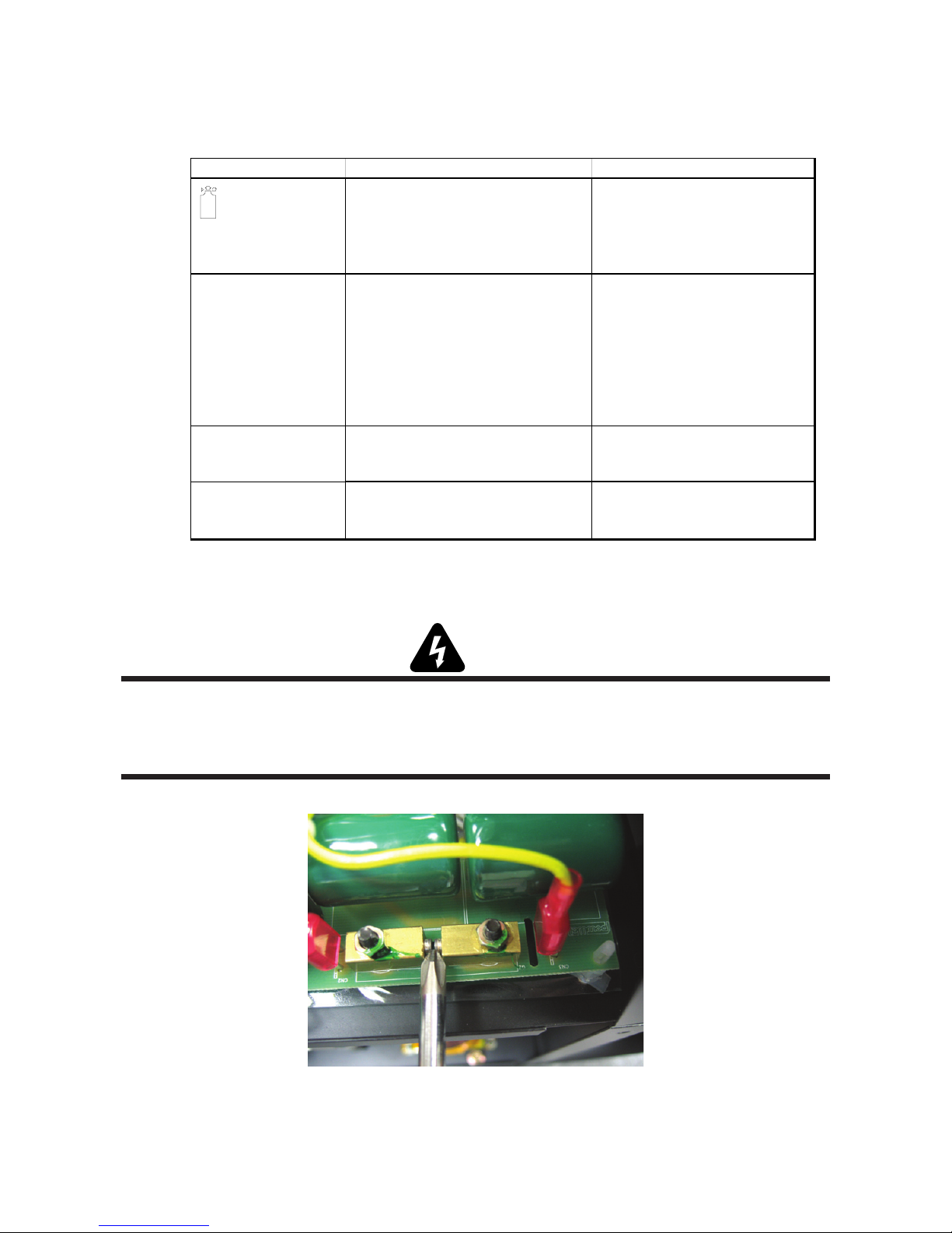
A. Diode Testing Basics
WARNING
There are extremely dangerous voltage and power levels present inside this unit. Do not attempt to diagnose or repair
unless you have had training in power electronics measurement and troubleshooting techniques. Disconnect primary
power at the source before disassembling the power supply, torch, or torch leads. Discharge power at the H/V spark gap
using a metal tipped screw driver as shown:
Art # A-07116
Manual 0-4745 6-5 TROUBLE SHOOTING
Page 28

Testing of diode modules requires a digital volt/ohmmeter that has a diode test scale. Remember that even if the
diode module checks good, it may still be bad. If in doubt, replace the diode module.
1. Remove AC power. Refer to Appendix 3 Wiring diagram.
2. Locate the IGBT diode module to be tested.
3. Remove P5 from IGBT module.
4. Set digital volt/ohmmeter to diode test scale.
5. Connect the volt/ohmmeter positive lead to the anode (+) of the diode and the negative lead to the cathode (-) of
the diode for forward bias testing (refer to following figure). A properly functioning diode will conduct in the
forward bias direction and indicate between 0.3 to 0.9 volts.
Art # A-00307
0.75
Forward Bias
Diode Conducting
Diode Test Symbol
Anode
VR
+
COM
_
A
Cathode
Testing Diode Forward Bias
TROUBLE SHOOTING 6-6 Manual 0-4745
Page 29

6. Reverse the meter leads across the diode for reverse bias testing (refer to following figure). A properly functioning diode will block in the reverse bias direction and depending on the meter function will indicate an open or
“OL”.
Art # A-00306
OL
Reverse Bias
Diode Not Conducting
Cathode
Anode
+
VR
COM
_
A
Testing Diode Reverse Bias
7 Using the Figures for each test, check each diode in the module. Each diode must be checked in forward bias
(plus to negative) and reverse bias (negative to plus) direction.
Manual 0-4745 6-7 TROUBLE SHOOTING
Page 30

B. Component Tests
WARNING
Disconnect primary power at the source before taking any resistance checks.
1. Input Diode Module Board Circuit Test
a. Check Input Diode for short per schematic located in Appendix 4.
2. IGBT Module Test
a. With an ohmmeter set on the diode range remove P5 from the IGBT and make the following IGBT checks:
Gate PCB J5 IGBT Check
+-
E1 White + DD (1.020)
White + E1 Open After Charging
E1 Black - Open After Charging
Black - E1 DD (1.270)
E1 G1 DD (.770)
G1 E1 DD (.770)
E2 G2 DD (.770)
G2 E2 DD (.770)
E3 White + DD (1.270)
White + E3 Open After Charging
E3 Black - DD (.770)
Black - E3 DD (.770)
G3 E3 DD (.770)
E3 G3 DD (.770)
G4 E4 DD (.770)
E4 G4 DD (.770)
P5 Gate Connector
1 G1 Black 1 Black
2 E1 White 2 White
3G2 Green 3 Green
4 E2 Red 4 Red
5 G3 Black 1 Black
6 E3 White 2 White
7G4 Green 3 Green
8 E4 Red 4 Red
b. If reading is not as shown, replace both IGBT modules and Gate PCB.
c. Reconnect P5 connector.
TROUBLE SHOOTING 6-8 Manual 0-4745
Diode Test
Control Connector
TW
CN8
TW
TW
CN6
TW
Pin-out diagram
Page 31

6.06 Torch Tests
2
1
WARNING
Disconnect primary power at the source before disassembling the power supply, torch, or torch leads.
1. PIP and Torch Switch Adapter Check
a. Disconnect input power from power supply.
b. Confirm that the torch parts are in place and that they match the parts consumables label on the power
supply cover.
c. Refer to Appendix 2 for torch connection and access. With the power supply on it's side and the panel
removed, disconnect the Power Supply Adapter from the power supply.
d. While the torch trigger is depressed, complete an Ohm check on the two pins in the Power Supply Adapter
. The reading should show a short (less than 1 Ohm). Refer to diagram.
Negative / Plasma Lead
PIP
Switch
Torch
Switch
Torch Head
Black
Orange
Green
White
Pilot
Torch Leads
To Power
Supply Adapter
Continuity
Check
Pilot
Art # A-05557
2. Shorted Torch Check
a. Disconnect input power from power supply.
b. Disconnect the pilot lead (see previous diagram).
c. Perform an Ohm check of the pilot lead to the negative lead. This should show "Open". If it does not show
"Open", check that the correct consumables were installed per the consumables label on the unit cover.
d. Replace Torch as needed.
NOTE
Every effort has been made to provide complete and accurate information in this manual. However, the
publisher does not assume and hereby disclaims any liability to any party for any loss or damage caused by
errors or omissions in this Manual, whether such errors result from negligence, accident, or any other cause.
Manual 0-4745 6-9 TROUBLE SHOOTING
Page 32

This Page Left Blank
TROUBLE SHOOTING 6-10 Manual 0-4745
Page 33

SECTION 7:
PARTS LIST
General Information
This parts list covers the CutSkill
not use these instructions or parts on any other equipment.
Provide the power supply model number and serial number when ordering parts.
If a product must be returned for service, contact your distributor. Materials returned without proper authoriza-
tion will not be accepted.
Contact Information
Thermal Dynamics Technical Service Dept.
Tel: 1-800-752-7622 (1-800-PLASMA2)
Fax: 1-800-221-4401
e-mail address: tdc-tech@thermadyne.com
Replacement parts are shown on the following pages. Catalog numbers are shown below each part.
®
Model C-35C Plasma Cutting Power Supply with Internal Air Compressor. Do
Manual 0-4745 7-1 PARTS LIST
Page 34

7.01 Parts List Power Supply
Item Number Quantity Description Catalog Number
1 1 Cable Ground PG29 9-0382
2 1 Case, Front 9-0309
3 1 PCB-Front 9-7117
4 1 Circuit Breaker 9-7143
5 1 Cover Ass embly 35C 9-0310
6 1 Cooling Fan 9-7163
7 1 Power Cord Strain Relief 9-0296
8 1 Case, Back 9-0311
9 1 Case, Top 9-0312
10 1 PCB-Control 9-7181
11 1 H/V PCB 9-7147
12 1 Relay 9-0319
13 1 Resistor 9-0300
14 1 Control Transformer 9-7144
15 1 Bracket, Capacitor 9-0302
16 1 Electrolytic Capacitor As sembly 9-0303
17 1 Bracket, Upper 9-0313
18 1 Compress or Part 9-0320
19 1 Current Sensor 9-7153
20 1 PCB-Input Filter (shown) 9-7128
20 1 PCB-Input Filter (CE) 9-7133
21 1 Heat Sink Assembly 9-0306
22 1 Case, Torch Cover 9-0314
23 1 Connector 9-0305
24 1 Pilot Relay Assembly 9-0304
25 1 Main Trans and Reactor As sy 9-0315
26 1 Compress or Assembly 9-0316
27 1 Rubber Bushing 9-0318
28 1 PCB-Torch Filter 9-7121
29 1 Case, Bottom 9-0317
PARTS LIST 7-2 Manual 0-4745
Page 35

5
2
1
4
3
6
8
7
Art # A-07768
11
20
10
9
19
12
13
14
15
16
18
Art # A-07769
17
Manual 0-4745 7-3 PARTS LIST
Page 36

22
21
23
24
25
Art
28
# A-07770
26
27
29
PARTS LIST 7-4 Manual 0-4745
Page 37

This Page Left Blank
Manual 0-4745 7-5 PARTS LIST
Page 38

7.02 Replacement Hand Torch Parts With Ergonomic Handle
Item # Qty Description Catalog #
1 1 Assembly, Basic Head
70° Head 9-8442
2 2 PIP (Parts - In - Place) Pins 9-5723
3 1 #6-32 x 3/16" Phillips Pan Head Screw See Note
4 1 #6 Internal Star Washer See Note
1 Ergonomic Handle, Split, with Trigger (includes items #5 - 12) 9-8076
5 1 Trigger, Lexan, Orange 9-8059
6 1 Handle 9-8060
7 1 Spring, 0.390 O.D. x 0.750 9-8061
8 1 Torch Handle Socket Head Cap Screw Kit (5 pcs 6-32 x 1/2" ) 9-8062
9 1 Assembly, Torch Switch 9-8063
10 1 Negative / Plasma Lead Insulation Sleeving 9-8056
11 3 Pin Housing (Used with item #12) 9-8111
12 3 Pin 9-8101
13 3 Socket Housing (Used with item #14) 9-8112
14 3 Socket 9-8102
15 1 Lead Assembly, including items No. 6, 8, and 9
20 ft (7.6 m) Length 4-2989
NOTE: Item can be purchased locally.
PARTS LIST 7-6 Manual 0-4745
Page 39

10
6
13 & 14
4
3
9
11 & 12
7
1
5
6
8
2
15
Art # A-07061
Manual 0-4745 7-7 PARTS LIST
Page 40

This Page Left Blank
PARTS LIST 7-8 Manual 0-4745
Page 41

Appendix 1: Operating Sequence, Block Diagram
Primary Input Power "On" or Plugged in
Power Supply On/Off Switch "On"
Red Air Indicator
Release Torch Switch
Pilot Arc Ignition (3-5 seconds)
Pilot Arc goes out
Green Power Indicator "On" and Fan is Running
Air Set Switch "On"
Compressor Starts and Air Flows at Torch. Turn Air Set Switch "Off"
Check Torch parts
Air Flow at Torch Stops
Torch Switch "On"
Torch Tip to Work within 3-5 seconds of Pilot Arc start
Start Cutting Operation
alignment. PIP switches
need to be repaired by a
Qualified Technician
Release Torch Switch
More air flow is required
for Torch to Pilot than to
run the power supply.
Compressor not functioning
properly need to be repaired
by a Qualified Technician
No Pilot Arc
YES
Post Flow of Air, Approximately 15 Seconds Then Stops
Note: The Torch will be very hot! Do not set on or near flammable materials!
Art # A-04694
Manual 0-4745 A-1 APPENDIX
Cutting Done ?
Torch Switch "Off"
Power Supply On/Off Switch "Off"
Green Power Indicator "Off" and Fan Stops
Primary Input Power Switch "Off" or Unplugged
NO
Page 42

Appendix 2: Torch Connection
Art # A-04695
Disconnect power and air. Lay unit
on its side. Remove two screws and
access plate.
DETAIL
Power Supply
Adapter Connections
Negative / Plasma Lead
To Power
Supply Adapter
Pilot
APPENDIX A-2 Manual 0-4745
Pilot
Black
Orange
Green
White
Negative / Plasma Lead
Pilot
Torch Leads
PIP
Switch
Torch
Switch
Torch Head
Page 43

Appendix 3: Microchip Pin-Out
40 Pin Microchip
123456789101112
24222018161412108642
2321191715131197531
CPU
Socket on
Control
PCB
P2
P1
P3 123456789101112
Manual 0-4745 A-3 APPENDIX
Page 44

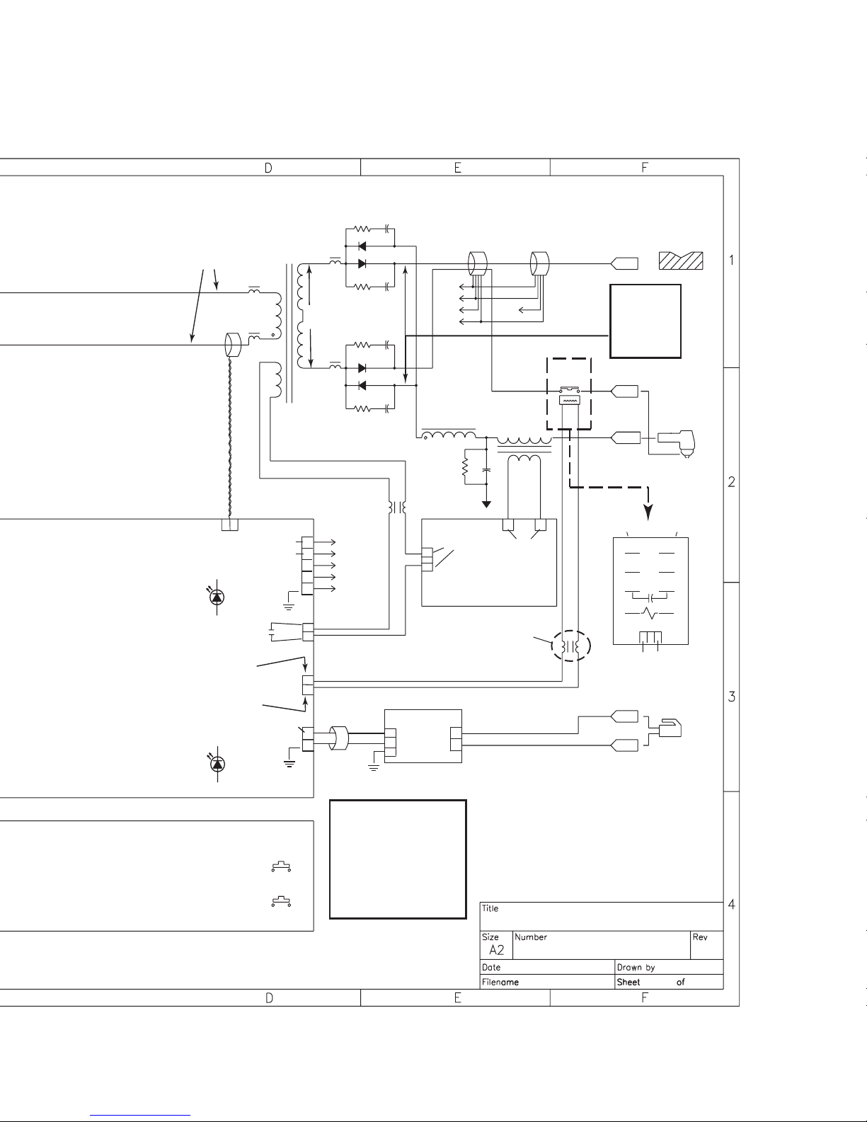
Appendix 4: System Schematic 230V CE
L
INPUT
AC230V
N
1 PH
G
NOTE:
Do Not
attempt to
adjust the
PCB POTs!
W
Br
NFB
230 VAC
Bl
Bl
R
Bk
R
R
Bl
TB2
Bk
1
W
N/C
3
W
R
W,2
Located on IGBT
Heatsink
N/C
Or
Or
C3
Capacitor
W
W
Bk
11
230 VAC
TB1
2
Wh
3
Inrush Filter PCB
CN2
13 3 3 31
W
W
230 VAC
580
Ω
FAN
AC230
230 VAC
Lt
W
Bl
Br
N/C
3
1
Comp
Relay
4
N/C
Compressor Relay
R
75
Jumper
826
Bl
230 VAC
No.40276005
CN1 CN4THCN3
1
WW
Bk Bk
R1
Ω
50
T1
AC12
AC18
AC18
672Ω
MF 103K
630V
Pressure
Sensor
DIODE
DC
325
R2
C2
+
N/C
N/C
(-)
+12VDC
2
1
2
1
2
1
Red
C2
Bk
Bk,2
CN5
CN1
+25VDC
CN4
+12VDC
CN7
IGBT
C3
R2
E1 G2
G1
E2 G4
G3 E4E3
TW TW TW TW
B W G R B W G R
E4 G3 G2G4 E3 E1E2 G1
CN6
LD1
SOL
Control Board
No.40271005
LD3
CO
CN2
IGBT
CN8
Compressor
Art # A-06978
APPENDIX A-4 Manual 0-4745
CN1
Bl
C1
Bl
MAIN
POWER
Panel Board
No.40270601
TEMP
AIR
ERROR
ERROR
HOLD
Page 45
No H.F.
On
220
VAC
Bk
LD2
Enable
Bk
C/T 1
CN9
Main Tra nsformer
W
Twi sted
+12VDC
-12VDC
CN10
190VAC
1
2
3
4
5
VC_1
VD_1
OU_1
OU_2
GN_1
C4
R3
Current Sensor
+
C5
R4
R5
C6
C7
R6
BR
Red
O
Y
(-)
VC_1
VD_1
OU_1
GN_1
REACTOR
1
3
CN1
R7
36VAC
10k Ω
O
F/G
G
Br
OU_2
Conduit Coil
C8
Spark Gap
H/V Board
No.40273003
R
Y
G
Pilot
Relay
WW
80
Ω
WORK
O.C.V. 325
Pilot 130
Cutting 80-100
(See Sec. 6 OCV
in Service Manual)
PILOT
TORCH
WW
PCR
H/V Contactor
+12VDC
to engage
Pilot Relay
LD4
H/V
HOLD
AIR
CHECK
CN11
CN12
+12VDC
CN3
2
1
1
2
2
1
W
W
NOTE:
Do Not attempt to
adjust the PCB
POTs!
Torc h
Filter
No. 40276002
Bk (1 only)
Y
Y
Air Plasma 35C (230V CE)
No. 66001012
oct. 19. 2005
S/W
S/W
Y
**PCB not removable from relay
Y
AA
Art # A-06978
Manual 0-4745 A-5 APPENDIX
Page 46

Appendix 5: System Schematic 230V
INPUT
AC230V
1 PH
NOTE:
Do Not
attempt to
adjust the
PCB POTs!
230 VAC
NFB
L
N
G
Br
W
Bk
11
230 VAC
TB1
2
Wh
3
CN2
13 3 3 31
W
W
Filter Board
230 VAC
580
Ω
FAN
AC230
230 VAC
Lt
W
Bl
Br
N/C
3
1
Comp
Relay
4
N/C
Compressor Relay
R
75
Jumper
826
Bl
230 VAC
No.40276003
CN1 CN4THCN3
1
WW
Bk Bk
R1
Ω
50
T1
AC12
AC18
AC18
672Ω
MF 103K
630V
Pressure
Sensor
TB2
3
1
Bk
R
Bl
Bl
R
Bk
R
R
Bl
DIODE
W
N/C
W
C3
W,2
+
Capacitor
Located on IGBT
Heatsink
N/C
W
W
N/C
N/C
Or
Or
Compressor
DC
325
R2
C2
(-)
2
1
2
1
2
1
Red
C2
Bk
Bk,2
+12VDC
CN5
CN1
+25VDC
CN4
+12VDC
CN7
IGBT
C3
R2
E1 G2
G1
G3 E4E3
E2 G4
TW TW TW TW
B W G R B W G R
E4 G3 G2G4 E3 E1E2 G1
CN6
LD1
SOL
Control Board
LD3
CO
CN2
CN1
IGBT
CN8
No.40271005
Panel Board
No.40270601
Art # A-07024
APPENDIX A-6 Manual 0-4745
Bl
C1
Bl
MAIN
POWER
TEMP
ERROR
AIR
ERROR
HOLD
Page 47

No H.F.
On
220
VAC
Bk
LD2
Enable
Bk
C/T 1
CN9
Main Tra nsformer
W
Twi sted
+12VDC
-12VDC
CN10
190VAC
1
2
3
4
5
VC_1
VD_1
OU_1
OU_2
GN_1
C4
R3
Current Sensor
+
C5
R4
R5
C6
C7
R6
BR
Red
O
Y
(-)
REACTOR
1
3
CN1
VC_1
VD_1
OU_1
GN_1
36VAC
10k Ω
O
R7
F/G
G
Br
OU_2
Conduit Coil
C8
Spark Gap
H/V Board
No.40273003
R
Y
G
Pilot
Relay
WW
80
Ω
WORK
O.C.V. 325
Pilot 130
Cutting 80-100
(See Sec. 6 OCV
in Service Manual)
PILOT
TORCH
WW
PCR
H/V Contactor
+12VDC
to engage
Pilot Relay
LD4
H/V
HOLD
AIR
CHECK
CN11
CN12
+12VDC
CN3
2
1
1
2
2
1
W
W
Torc h
Filter
No. 40276002
Bk (1 only)
Y
Y
S/W
S/W
**PCB not removable from relay
Y
Y
NOTE:
Do Not attempt to
adjust the PCB
POTs!
Air Plasma 35C (230V )
No. 66001008
oct. 19. 2005
AB
Art # A-07024
Manual 0-4745 A-7 APPENDIX
Page 48

This Page Left Blank
APPENDIX A-8 Manual 0-4745
Page 49

GLOBAL CUSTOMER SERVICE CONTACT INFORMATION
Thermadyne USA
2800 Airport Road
Denton, Tx 76207 USA
Telephone: (940) 566-2000
800-426-1888
Fax: 800-535-0557
Email: sales@thermalarc.com
Thermadyne Canada
2070 Wyecroft Road
Oakville, Ontario
Canada, L6L5V6
Telephone: (905)-827-1111
Fax: 905-827-3648
Thermadyne Europe
Europe Building
Chorley North Industrial Park
Chorley, Lancashire
England, PR6 7Bx
Telephone: 44-1257-261755
Fax: 44-1257-224800
Thermadyne Asia Sdn Bhd
Lot 151, Jalan Industri 3/5A
Rawang Integrated Industrial Park - Jln Batu Arang
48000 Rawang Selangor Darul Ehsan
West Malaysia
Telephone: 603+ 6092 2988
Fax : 603+ 6092 1085
Cigweld, Australia
71 Gower Street
Preston, Victoria
Australia, 3072
Telephone: 61-3-9474-7400
Fax: 61-3-9474-7510
Thermadyne Italy
OCIM, S.r.L.
Via Benaco, 3
20098 S. Giuliano
Milan, Italy
Tel: (39) 02-98 80320
Fax: (39) 02-98 281773
Thermadyne, China
RM 102A
685 Ding Xi Rd
Chang Ning District
Shanghai, PR, 200052
Telephone: 86-21-69171135
Fax: 86-21-69171139
Thermadyne International
2070 Wyecroft Road
Oakville, Ontario
Canada, L6L5V6
Telephone: (905)-827-9777
Fax: 905-827-9797
Page 50

Corporate Headquarters
16052 Swingley Ridge Road
Suite 300
St. Louis, MO 63017
Telephone: 636-728-3000
Email: TDCSales@Thermadyne.com
www.thermadyne.com
 Loading...