

Page 1

40
A40i, A60i
PLASMA CUTTING SYSTEM
60
208-
480V
380-
415V
OPERATING
MANUAL
Revision: AB Issue Date: 7/3/2018 Manual No.: 0-5466
thermal-dynamics.com
Page 2

WE APPRECIATE YOUR BUSINESS!
Congratulations on your new Thermal Dynamics product. We are proud to have you as our customer
and will strive to provide you with the best service and reliability in the industry. This product is backed
by our extensive warranty and world-wide service network. To locate your nearest distributor or service
agency call 1-866-279-2628, or visit us on the web at www.Thermal-Dynamics.com.
This Operating Manual has been designed to instruct you on the correct use and operation of your
Thermal Dynamics product. Your satisfaction with this product and its safe operation is our ultimate
concern. Therefore please take the time to read the entire manual, especially the Safety Precautions.
They will help you to avoid potential hazards that may exist when working with this product.
YOU ARE IN GOOD COMPANY!
The Brand of Choice for Contractors and Fabricators Worldwide.
Thermal Dynamics is a Global Brand of manual and automation Plasma Cutting Products.
We distinguish ourselves from our competition through market-leading, dependable products that
have stood the test of time. We pride ourselves on technical innovation, competitive prices, excellent delivery, superior customer service and technical support, together with excellence in sales and
marketing expertise.
Above all, we are committed to developing technologically advanced products to achieve a safer
working environment within the welding industry.
Page 3

WARNING
Read and understand this entire Manual and your employer’s safety practices
!
before installing, operating, or servicing the equipment.
While the information contained in this Manual represents the Manufacturer’s
best judgement, the Manufacturer assumes no liability for its use.
Plasma Cutting Power Supplies
A40i, A60i
SL100SV 1Torch™
Operating Manual Number 0-5466
Published by:
Thermal Dynamics
2800 Airport Rd.
Denton, Texas 76207
www.Thermal-Dynamics.com
© Copyright 2017 by
Thermal Dynamics .
All rights reserved.
Reproduction of this work, in whole or in part, without written permission of the publisher is
prohibited.
The publisher does not assume and hereby disclaims any liability to any party for any loss or
damage caused by any error or omission in this Manual, whether such error results from negligence, accident, or any other cause.
For Material Print Specifications, refer to document 47x1909
Original Publication Date: 16 November, 2017
Revision Date: 7/3/18
Record the following information for Warranty purposes:
Where Purchased:_______________________________ __________________
Purchase Date:__________________________________ __________________
Power Supply Serial #:___________________________ ___________________
Torch Serial #:___________________________________ _________________
i
Page 4

Be sure this information reaches the operator.
You can get extra copies through your supplier.
CAUTION
These INSTRUCTIONS are for experienced operators. If you are not fully familiar
with the principles of operation and safe practices for arc welding and cutting equipment, we urge you to read our booklet, “Precautions and Safe Practices for Arc
Welding, Cutting, and Gouging,” Form 52-529. Do NOT permit untrained persons to
install, operate, or maintain this equipment. Do NOT attempt to install or operate this
equipment until you have read and fully understand these instructions. If you do not
fully understand these instructions, contact your supplier for further information. Be
sure to read the Safety Precautions before installing or operating this equipment.
USER RESPONSIBILITY
This equipment will perform in conformity with the description thereof contained in this manual and accompanying labels and/or inserts when installed, operated, maintained and repaired in accordance with the
instructions provided. This equipment must be checked periodically. Malfunctioning or poorly maintained equipment should not be used. Parts that are broken, missing, worn, distorted or contaminated should be replaced
immediately. Should such repair or replacement become necessary, the manufacturer recommends that a telephone or written request for service advice be made to the Authorized Distributor from whom it was purchased.
This equipment or any of its parts should not be altered without the prior written approval of the manufacturer. The user of this equipment shall have the sole responsibility for any malfunction which results from
improper use, faulty maintenance, damage, improper repair or alteration by anyone other than the manufacturer or a service facility designated by the manufacturer.
READ AND UNDERSTAND THE INSTRUCTION MANUAL BEFORE INSTALLING OR
!
OPERATING.
PROTECT YOURSELF AND OTHERS!
Page 5

ASSUREZ-VOUS QUE CE DOCUMENT D’INFORMATION EST DISTRIBUÉ À L’OPÉRATEUR.
DES COPIES SUPPLÉMENTAIRES SONT DISPONIBLES CHEZ VOTRE FOURNISSEUR.
MISE EN GARDE
Les INSTRUCTIONS suivantes sont destinées aux opérateurs qualiés seulement. Si
vous n’avez pas une connaissance approfondie des principes de fonctionnement et
des règles de sécurité applicables au soudage à l’arc et à l’équipement de coupage,
nous vous suggérons de lire notre brochure « Précautions et pratiques de sécurité
pour le soudage à l’arc, le coupage et le gougeage », Formulaire 52-529. Ne permettez
PAS aux personnes non qualiées d’installer, d’utiliser ou d’effectuer des opérations
de maintenance sur cet équipement cet équipement. Ne tentez PAS d’installer ou
d’utiliser cet équipement avant d’avoir lu et bien compris ces instructions. Si vous ne
comprenez pas bien les instructions, renseignez-vous auprès de votre fournisseur.
Assurez-vous de lire les Règles de Sécurité avant d’installer ou d’utiliser cet
équipement.
RESPONSABILITÉS DE L’UTILISATEUR
Cet équipement fonctionnera conformément à la description contenue dans ce manuel, les étiquettes
d’accompagnement et/ou les feuillets d’information à condition d’être installé, utilisé, entretenu et réparé selon
les instructions fournies. L’équipement doit être contrôlé de manière périodique. Ne jamais utiliser un équipement qui ne fonctionne correctement bien ou n’est pas bien entretenu. Les pièces qui sont brisées, usées,
déformées ou contaminées doivent être remplacées immédiatement. Dans le cas où une réparation ou un
remplacement est nécessaire, e fabricant recommande de faire une demande de conseil de service écrite ou
par téléphone auprès du distributeur agréé où l’équipement a été acheté.
Cet équipement ou ses pièces ne doivent pas être modiés sans permission préalable écrite du fabricant.
L’utilisateur de l’équipement sera le seul responsable de toute défaillance résultant de toute utilisation, mainte-
nance, réparation incorrectes, de dommages ou encore de modication apportées par une personne autre que
le fabricant ou un centre de service désigné par ce dernier.
ASSUREZ-VOUS DE LIRE ET DE COMPRENDRE LE MANUEL D’UTILISATION AVANT
!
D’INSTALLER OU D’UTILISER L’UNITÉ.
PROTÉGEZ-VOUS ET LES AUTRES!
Page 6

This Page Intentionally Blank
Page 7

EU DECLARATION OF CONFORMITY
According to
The Low Voltage Directive 2014/35/EU, entering into force 20 April 2016
The EMC Directive 2014/30/EU, entering into force 20 April 2016
The RoHS Directive 2011/65/EU, entering into force 2 January 2013
Type of equipment
PLASMA CUTTING SYSTEM
Type designation etc.
A40i and A60i, from serial number MX1723XXXXXX
Brand name or trade mark
Thermal Dynamics
Manufacturer or his authorised representative
Name, address, telephone No:
ESAB Group Inc.
2800 Airport Rd
Denton TX 76207 USA
Phone: +01 800 426 1888, FAX +01 603 298 7402
The following harmonised standard in force within the EEA has been used in the design:
IEC/EN 60974-1:2012 Arc Welding Equipment - Part 1: Welding power sources.
IEC/EN 60974-10:2014 + AMD 1:2015 Published 2015-06-19 Arc Welding Equipment - Part 10: Electromagnetic
compatibility (EMC) requirements
Additional Information: Restrictive use, Class A equipment, intended for use in location other than residential.
By signing this document, the undersigned declares as manufacturer, or the manufacturer’s authorised
representative , that the equipment in question complies with the safety requirements stated above.
Date Signature Position
10 October, 2017 Vice President,
John Boisvert Global Cutting
Mechanized Cutting
2017
Page 8

is Page Intentionally Blank
Page 9

TABLE OF CONTENTS
SECTION 1:
GENERAL INFORMATION .................................................................................................................... 1-1
1.01 Notes, Cautions and Warnings ............................................................................................................. 1-1
WARRANTY:
.............................................................................................................................................. W-1
Statement of Warranty ......................................................................................................................................... W-1
SECTION 2 SYSTEM:
INTRODUCTION
2.01 How To Use This Manual ...................................................................................................................... 2-1
2.02 Equipment Identication .................................................................................................................... 2-1
2.03 Receipt Of Equipment ......................................................................................................................... 2-2
2.04 Power Supply Specications ................................................................................................................ 2-2
2.05 Input Wiring Specications ................................................................................................................. 2-3
2.06 Power Supply Features ........................................................................................................................ 2-4
2.07 Power Supply Placement ..................................................................................................................... 2-4
SECTION 2 TORCH:
INTRODUCTION
2T.01 Scope of Manual .................................................................................................................................2T-1
2T.02 General Description ............................................................................................................................2T-1
2T.03 Specications ....................................................................................................................................2T-1
2T.04 Quick Connection Torch .....................................................................................................................2T-2
2T.05 Options And Accessories .....................................................................................................................2T-2
2T.06 Introduction to Plasma .......................................................................................................................2T-2
SECTION 3 SYSTEM:
INSTALLATION
3.01 Unpacking ........................................................................................................................................... 3-1
3.02 Lifting Options .................................................................................................................................... 3-1
3.03 Power Supply location and Mounting ................................................................................................. 3-1
3.04 Opening the Main Switch Cover .......................................................................................................... 3-2
3.05 Primary Input Power Connections ....................................................................................................... 3-2
3.06 Primary Input Power Connections, THREE Phase ................................................................................. 3-3
3.07 Gas Connections .................................................................................................................................. 3-4
3.08 Work Lead Connections ....................................................................................................................... 3-7
................................................................................................................................ 2-1
...............................................................................................................................2T-1
.................................................................................................................................. 3-1
SECTION 3 TORCH:
INSTALLATION
.................................................................................................................................3T-1
3T.01 Torch Connections .............................................................................................................................. 3T-1
3T.02 Setting Up Mechanical Torch ..............................................................................................................3T-1
SECTION 4 SYSTEM:
OPERATION
...................................................................................................................................... 4-1
4.01 Front Panel Controls / Features ............................................................................................................ 4-1
4.02 Preparations for Operation .................................................................................................................. 4-4
4.03 Marking .............................................................................................................................................. 4-8
Page 10

TABLE OF CONTENTS
SECTION 4 TORCH:
OPERATION ......................................................................................................................................4T-1
4T.01 Machine and Automated Torch Operation ..........................................................................................4T-1
4T.02 Automation Torch Parts Selection .......................................................................................................4T-1
4T.03 Machine and Hand Torch Parts Selection ............................................................................................4T-2
4T.04 Cut Quality .........................................................................................................................................4T-3
4T.05 General Cutting Information ..............................................................................................................4T-4
4T.06 Hand Torch Operation .........................................................................................................................4T-5
4T.07 Gouging ............................................................................................................................................. 4T-8
4T.08 Recommended Cutting Speeds for Machine and Automated Torches With Exposed Tip .................... 4T-10
4T.09 Recommended Cutting Speeds for Machine and Automated Torches With Shielded Tip ................... 4T-22
PATENT INFORMATION
SECTION 5 SYSTEM:
SERVICE
............................................................................................................................................ 5-1
5.01 General Maintenance .......................................................................................................................... 5-1
5.02 Maintenance Schedule ........................................................................................................................ 5-2
5.03 Common Faults ................................................................................................................................... 5-3
5.04 Fault Indicator ..................................................................................................................................... 5-4
5.05 Basic Troubleshooting Guide ............................................................................................................... 5-5
5.06 Power Supply Basic Parts Replacement ............................................................................................... 5-7
SECTION 5 TORCH:
SERVICE
...........................................................................................................................................5T-1
5T.01 General Maintenance .........................................................................................................................5T-1
5T.02 Inspection and Replacement of Consumable Torch Parts ....................................................................5T-2
SECTION 6:
PARTS LISTS
...................................................................................................................................... 6-1
6.01 Introduction ........................................................................................................................................ 6-1
6.02 Ordering Information .......................................................................................................................... 6-1
6.03 Power Supply Replacement ................................................................................................................. 6-1
6.04 Replacement Power Supply Parts ........................................................................................................ 6-2
6.05 Options and Accessories ...................................................................................................................... 6-2
6.06 Torch Replacement Parts SL100SV Torch (with Solenoid on Mounting Tube) ....................................... 6-4
6.07 Replacement Parts - for Machine Torches with Unshielded Leads ....................................................... 6-6
6.08 Torch Consumable Parts Automation / Machine (SL100)Torch ............................................................. 6-8
.............................................................................................................................4T-34
Page 11

TABLE OF CONTENTS
APPENDIX 1: SEQUENCE OF OPERATION
(BLOCK DIAGRAM) ............................................................................................................................. A-1
APPENDIX 2: DATA TAG INFORMATION
APPENDIX 3: TORCH PIN - OUT DIAGRAMS
APPENDIX 4: TORCH CONNECTION DIAGRAMS
APPENDIX 5: CNC CABLE COLOR CODE
APPENDIX 6: AUTOMATION INTERFACE
......................................................................................................... A-2
................................................................................................... A-3
.............................................................................................. A-4
.......................................................................................................... A-5
........................................................................................................ A-6
APPENDIX 7: SYSTEM SCHEMATIC, 208/480V 1PHASE
APPENDIX 8: SYSTEM SCHEMATIC, 400V 3PHASE CE
APPENDIX 9: SYSTEM SCHEMATIC, 208/480V 3PHASE
APPENDIX 10: PUBLICATION HISTORY
....................................................................................................... A-14
................................................................................... A-8
.................................................................................... A-10
................................................................................. A-12
Page 12

This Page Intentionally Blank
TABLE OF CONTENTS
Page 13

A40i, A60i
SECTION 1:
GENERAL INFORMATION
1.01 Notes, Cautions and Warnings
Throughout this manual, notes, cautions, and warnings are used to highlight important information. These highlights are categorized as follows:
NOTE!
An operation, procedure, or background information which requires additional emphasis or is helpful in ecient operation of the system.
CAUTION
A procedure which, if not properly followed, may cause damage to the equipment.
!
WARNING
A procedure which, if not properly followed, may cause injury to the operator or others in the operating area.
WARNING
Gives information regarding possible electrical shock injury.
Manual 0-5466 GENERAL INFORMATION
1-1
Page 14
A40i, A60i
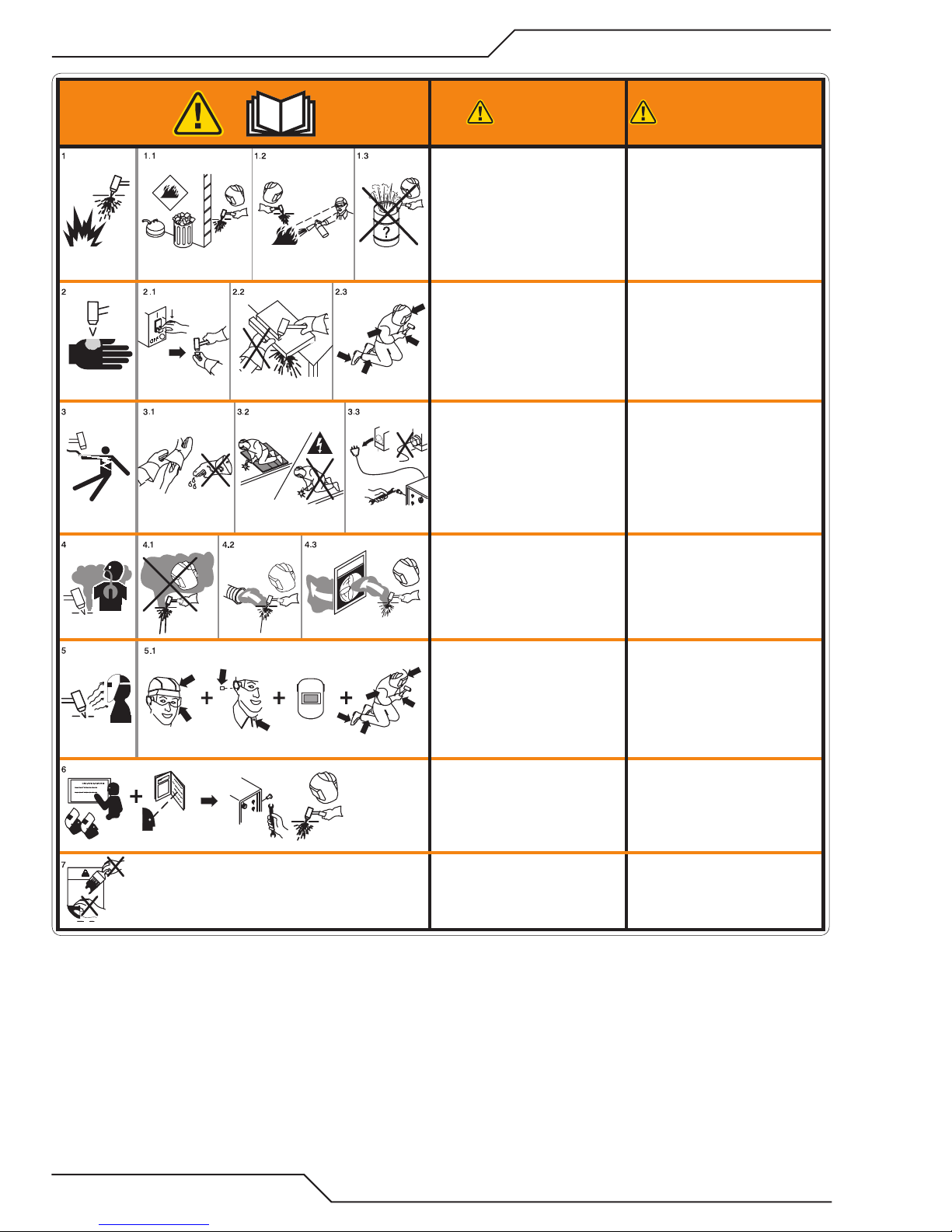
WARNING
1. Cutting sparks can cause explosion
or fire.
1.1 Do not cut near flammables.
1.2 Have a fire extinguisher nearby and
ready to use.
1.3 Do not use a drum or other closed
container as a cutting table.
2. Plasma arc can injure and burn;
point the nozzle away from
yourself. Arc starts instantly when
triggered.
2.1 Turn o power before disassembling
torch.
2.2 Do not grip the workpiece near the
cutting path.
2.3 Wear complete body protection.
3. Hazardous voltage. Risk of electric
shock or burn.
3.1 Wear insulating gloves. Replace
gloves when wet or damaged.
3.2 Protect from shock by insulating
yourself from work and ground.
3.3 Disconnect power before servicing.
Do not touch live parts.
4. Plasma fumes can be hazardous.
4.1 Do not inhale fumes.
4.2 Use forced ventilation or local
exhaust to remove the fumes.
4.3 Do not operate in closed spaces.
Remove fumes with ventilation.
5. Arc rays can burn eyes and injure
skin.
5.1 Wear correct and appropriate
protective equipment to protect
head, eyes, ears, hands, and body.
Button shirt collar. Protect ears from
noise. Use welding helmet with the
correct shade of filter.
6. Become trained.
Only qualified personnel should
operate this equipment. Use torches
specified in the manual. Keep
non-qualified personnel and children
away.
7. Do not remove, destroy, or cover
this label.
Replace if it is missing, damaged,
or worn.
AVERTISSEMENT
1. Les étincelles de coupage peuvent
provoquer une explosion ou un
incendie.
1.1 Ne pas couper près des matières
inflammables.
1.2 Un extincteur doit être à proximité
et prêt à être utilisé.
1.3 Ne pas utiliser un fût ou un autre
contenant fermé comme table de
coupage.
2. L’arc plasma peut blesser et brûler;
éloigner la buse de soi. Il s’allume
instantanément quand on l’amorce.
2.1 Couper l’alimentation avant de
démonter la torche.
2.2 Ne pas saisir la pièce à couper de la
trajectoire de coupage.
2.3 Se protéger entièrement le corps.
3. Tension dangereuse. Risque de
choc électrique ou de brûlure.
3.1 Porter des gants isolants. Remplacer
les gants quand ils sont humides ou
endommagés.
3.2 Se protéger contre les chocs en
s’isolant de la pièce et de la terre.
3.3 Couper l’alimentation avant
l’entretien. Ne pas toucher les pièces
sous tension.
4. Les fumées plasma peuvent être
dangereuses.
4.1 Ne pas inhaler les fumées.
4.2 Utiliser une ventilation forcée ou un
extracteur local pour dissiper les
fumées.
4.3 Ne pas couper dans des espaces clos.
Chasser les fumées par ventilation.
5. Les rayons d’arc peuvent brûler les
yeux et blesser la peau.
5.1 Porter un bon équipement de
protection pour se protéger la tête,
les yeux, les oreilles, les mains et le
corps. Boutonner le col de la chemise.
Protéger les oreilles contre le bruit.
Utiliser un masque de soudeur avec
un filtre de nuance appropriée.
6. Suivre une formation.
Seul le personnel qualifié a
le droit de faire fonctionner cet
équipement. Utiliser exclusivement
les torches indiquées dans le manual.
Le personnel non qualifié et les
enfants doivent se tenir à l’écart.
7. Ne pas enlever, détruire ni couvrir
cette étiquette.
La remplacer si elle est absente,
endommagée ou usée.
Art # A-13294
GENERAL INFORMATION Manual 0-5466
1-2
Page 15
A40i, A60i
Warranty:
Statement of Warranty
LIMITED WARRANTY: Subject to the terms and conditions established below, Thermal Dynamics warrants to the original
retail purchaser that new Thermal Dynamics plasma cutting systems sold after the effective date of this warranty are free
of defects in material and workmanship. Should any failure to conform to this warranty appear within the applicable
period stated below, Thermal Dynamics shall, upon notification thereof and substantiation that the product has been
stored operated and maintained in accordance with Thermal Dynamics’ specifications, instructions, recommendations
and recognized industry practice, correct such defects by suitable repair or replacement.
This warranty is exclusive and in lieu of any warranty of merchantability or tness for a particular purpose.
ESAB will repair or replace, at its discretion, any warranted parts or components that fail due to defects in material or
workmanship within the time periods set out below. Thermal Dynamics must be notified within 30 days of any failure,
at which time Thermal Dynamics will provide instructions on the warranty procedures to be implemented.
Thermal Dynamics will honor warranty claims submitted within the warranty periods listed below. All warranty periods
begin on the date of sale of the product to the original retail customer or 1 year after sale to an authorized Thermal
Dynamics Distributor.
LIMITED WARRANTY PERIOD
Product
Power Supply Components
(Parts and Labor)
Torch and Leads
(Parts and Labor)
U.S. Non U.S.
A40i, A60i 4 Years 3 Years 1 Year
This warranty does not apply to:
1. Consumable Parts, such as tips, electrodes, shield cups, o-rings, starter cartridges, gas distributors, fuses, filters.
2. Equipment that has been modified by an unauthorized party, improperly installed, improperly operated or misused
based upon industry standards.
In the event of a claim under this warranty, the remedies shall be, at the discretion of Thermal Dynamics :
1. Repair of the defective product.
2. Replacement of the defective product.
3. Reimbursement of reasonable costs of repair when authorized in advance by Thermal Dynamics.
4. Payment of credit up to the purchase price less reasonable depreciation based on actual use.
These remedies may be authorized by Thermal Dynamics and are FOB West Lebanon, NH or an authorized Thermal
Dynamics service station. Product returned for service is at the owner’s expense and no reimbursement of travel or
transportation is authorized.
LIMITATION OF LIABILITY: Thermal Dynamics shall not under any circumstances be liable for special or consequential
damages such as, but not limited to, damage or loss of purchased or replacement goods or claims of customer of distributors
(hereinafter “Purchaser”) for service interruption. The remedies of the Purchaser set forth herein are exclusive and the liability
Thermal Dynamics with respect to any contract, or anything done in connection therewith such as the performance or breach
of
thereof, or from the manufacture, sale, delivery, resale, or use of the goods covered by or furnished by
arising out of contract, negligence, strict tort, or under any warranty, or otherwise, shall not, except as expressly provided herein,
exceed the price of the goods upon which liability is based.
Thermal Dynamics whether
This warranty becomes invalid if replacement parts or accessories are used which may impair the safety or performance
of any Thermal Dynamics product.
This warranty is invalid if the Thermal Dynamics product is sold by non - authorized persons.
Effective July 18, 2017.
Manual 0-5466 WARRANTY INFORMATION
W-1
Page 16

A40i, A60i
This Page Intentionally Blank
WARRANTY INFORMATION Manual 0-5466
W-2
Page 17

A40i, A60i
!
SECTION 2 SYSTEM:
INTRODUCTION
2.01 How To Use This Manual
This Owner’s Manual applies to just specification or part numbers listed on page i.
To ensure safe operation, read the entire manual, including the chapter on safety instructions and warnings.
Throughout this manual, the words WARNING, CAUTION, and NOTE may appear. Pay particular attention to the
information provided under these headings. These special annotations are easily recognized as follows:
NOTE!
An operation, procedure, or background information which requires
additional emphasis or is helpful in
ecient operation of the system.
CAUTION
A procedure which, if not properly
followed, may cause damage to the
equipment.
WARNING
!
Additional copies of this manual may be purchased by contacting Thermal Dynamics at the address and phone
number in your area listed on back cover of this manual. Include the Operating Manual number and equipment
identification numbers.
Electronic copies of this manual can also be downloaded at no charge in Acrobat PDF format by going to the ESAB
web site listed below and clicking on "Product Support" / "ESAB Documentation": / "Download Library", then
navigate to "Plasma Equipment" and then "Manual".
http://www.esab.com
A procedure which, if not properly followed, may cause injury to the operator or others in the operating area.
WARNING
Gives information regarding possible
electrical shock injury. Warnings will
be enclosed in a box such as this.
2.02 Equipment Identification
The unit’s identification number (specification or part number), model, and serial number usually appear on a data
tag attached to the bottom. Equipment which does not have a data tag such as torch and cable assemblies are identified only by the specification or part number printed on loosely attached card or the shipping container. Record
these numbers on the bottom of page i for future reference.
Manual 0-5466 INTRODUCTION
2-1
Page 18

A40i, A60i
2.03 Receipt Of Equipment
When you receive the equipment, check it against the invoice to make sure it is complete and inspect the equipment
for possible damage due to shipping. If there is any damage, notify the carrier immediately to file a claim. Furnish
complete information concerning damage claims or shipping errors to the location in your area listed in the inside
back cover of this manual.
Include all equipment identification numbers as described above along with a full description of the parts in error.
Move the equipment to the installation site before un-crating the unit. Use care to avoid damaging the equipment when
using bars, hammers, etc., to un-crate the unit.
2.04 Power Supply Specifications
A60i Power Supply Specifications
Input Power 208 - 480 VAC, Single Phase, 50/60 Hz
Input Power Cable
Output Current 10 - 60 Amps, Continuously Adjustable
Power Supply Gas
Filtering Ability
Power Supply includes 9' single phase 6AWG 3/C input cable with NEMA
6-50P Plug..
Particulates to 5 Microns
A60i Power Supply Duty Cycle *
Ambient
Temperature
All Units
* NOTE: The duty cycle will be reduced if the primary input power (AC) is low or the output
Duty Cycle Ratings @ 40° C (104° F)
Operating Range 0° - 50° C
Rating
Duty Cycle 50% (208-230V ONLY) 80% 100%
Current
DC Voltage
voltage (DC) is higher than shown in this chart.
60 Amps 60 Amps 40 Amps
132 132 119
A60i
A40i Power Supply Specifications
Input Power 208 - 480 VAC, Single Phase, 50/60 Hz
Input Power Cable
Power Supply includes 9' single phase 8AWG
3/C input cable with NEMA 6-50P Plug..
Output Current 10 - 40 Amps, Continuously Adjustable
Power Supply Gas
Filtering Ability
Particulates to 5 Microns
A40i Power Supply Duty Cycle *
Ambient Temperature
All Units
* NOTE: The duty cycle will be reduced if the primary input power (AC)
is low or the output voltage (DC) is higher than shown in this chart.
INTRODUCTION Manual 0-5466
2-2
Duty Cycle Ratings @ 40° C (104° F)
Operating Range 0° - 50° C
Rating
Duty Cycle 80% 100%
Current
DC Voltage
40 Amps 30 Amps
119 119
A40i
Page 19
2.05 Input Wiring Specifications
A60i Power Supply Input Cable Wiring Requirements
Input voltage Freq Power Input Suggested Sizes
A40i, A60i
1 Phase
3 Phase
Fuse
Volts Hz kVA I max I
208 50/60 9.4 45.0 40.1 50 6 AWG (16 mm2)
230 50/60 9.4 40.8 36.3 50 8 AWG 10 mm2)
480 50/60 9.4 19.5 17.3 30 12 AWG (4 mm2)
208 50/60 9.8 27.3 24.3 50 8 AWG 10 mm2)
230 50/60 9.7 24.5 21.8 50 10 AWG (6 mm2)
380 50/60 9.5 14.5 12.9 30 14 AWG (2.5 mm2)
400 50/60 9.6 13.8 12.3 30 14 AWG (2.5 mm2)
415 50/60 9.6 13.4 11.9 30 14 AWG (2.5 mm2)
480 50/60 9.8 11.8 10.5 20 14 AWG (2.5 mm2)
Line Voltages with Suggested Circuit Protection and Wire Sizes
Based on National Electric Code and Canadian Electric Code
e
1
(amps)
Flexible Cord (Min.
AWG)
A40i Power Supply Input Cable Wiring Requirements
Input voltage Freq Power Input Suggested Sizes
Flexible Cord (Min.
Volts Hz kVA I max I
208 50/60 5.6 27.1 24.1 50 10 AWG (6 mm2)
eff Fuse (amps)
1
AWG)
1 Phase
3 Phase
230 50/60 5.6 24.5 21.8 50 12 AWG (4 mm2)
480 50/60 5.6 11.7 10.4 20 16 AWG (1.5 mm2)
208 50/60 5.9 16.4 14.6 25 12 AWG (4 mm2)
230 50/60 5.8 14.7 13.1 25 14 AWG (2.5 mm2)
380 50/60 5.7 8.7 7.7 15 16 AWG (1.5 mm2)
400 50/60 5.7 8.3 7.4 15 16 AWG (1.5 mm2)
415 50/60 5.8 8.0 7.2 15 16 AWG (1.5 mm2)
480 50/60 5.9 7.1 6.3 15 16 AWG (1.5 mm2)
Line Voltages with Suggested Circuit Protection and Wire Sizes
Based on National Electric Code and Canadian Electric Code
NOTE!
Refer to Local and National Codes or local authority having jurisdiction for proper wiring requirements.
Cable size is de-rated based on the Duty Cycle of the equipment.
Manual 0-5466 INTRODUCTION
2-3
Page 20

A40i, A60i
Torch Leads Receptacle
150 mm
2.06 Power Supply Features
Input Power Cord
Handle and Leads Wrap
Control Panel
Input Power ON/OFF Switch
Port for Optional Automation
Interface Cable
Gas Inlet Port
Filter Assembly
2.07 Power Supply Placement
7.847
199.3 mm
14.146"
359.3 mm
15"
381 mm
6"
150 mm
21.121"
35 lb / 15.875 kg
Power Supply Dimensions & Weight Ventilation Clearance Requirements
INTRODUCTION Manual 0-5466
2-4
536.47 mm
15"
381 mm
6"
Page 21

A40i, A60i
18.875" / 479 mm
16 mm
1.175" / 30 mm
2.875”
73 mm
SECTION 2 TORCH:
INTRODUCTION
2T.01 Scope of Manual
This manual contains descriptions, operating instructions and maintenance procedures for the 1Torch Models SL60QD™ hand torches and SL100SV Automated
Plasma Cutting Torches. Service of this equipment is
restricted to properly trained personnel; unqualified
personnel are strictly cautioned against attempting repairs or adjustments not covered in this manual, at the
risk of voiding the Warranty.
Read this manual thoroughly. A complete understanding
of the characteristics and capabilities of this equipment
will assure the dependable operation for which it was
designed.
2T.02 General Description
Plasma torches are similar in design to the automotive
spark plug. They consist of negative and positive sections separated by a center insulator. Inside the torch,
the pilot arc starts in the gap between the negatively
charged electrode and the positively charged tip. Once
the pilot arc has ionized the plasma gas, the superheated
column of gas flows through the small orifice in the torch
tip, which is focused on the metal to be cut.
A single torch lead provides gas from a single source
to be used as both the plasma and secondary gas. The
air flow is divided inside the torch head. Single - gas
operation provides a smaller sized torch and inexpensive
operation.
2T.03 Specifications
A. Torch Configurations
1. Automation Torch, Model
The standard automation torch has a positioning tube with rack & pinch block assembly and
a solenoid valve.
/
1.75" /
44.5 mm
0.625" /
2. Hand/Manual Torch, Models
The hand torch head is at 75° to the torch handle.
The hand torches include a torch handle and torch
trigger assembly.
3.75"
(95 mm)
1.17" (29 mm)
B. Torch Leads Lengths
Hand Torches are available as follows:
12.285" / 312 mm
1.375" / 35 mm
4.95" / 126 mm
10.125" (257 mm)
Art # A-07402_AC
Art # A-13633
NOTE!
Refer to Section "2T.05 Introduction to
Plasma", for a more detailed description of
plasma torch operation.
Refer to the Appendix Pages for additional
specifications as related to the Power Supply used.
Manual 0-5466 INTRODUCTION
• 20 ft / 6.1 m, with ATC connectors
• 50 ft / 15.2 m, with ATC connectors
Machine Torches are available as follows:
• 5 foot / 1.5 m, with ATC connectors
• 10 foot / 3.05 m, with ATC connectors
• 25 foot / 7.6 m, with ATC connectors
• 50 foot / 15.2 m, with ATC connectors
C. Torch Parts
Starter Cartridge, Electrode, Tip, Shield Cup
D. Parts - In - Place (PIP)
Torch Head has built - in switch
15 VDC circuit rating
E. Type Cooling
Combination of ambient air and gas stream through
torch.
2T-1
Page 22

A40i, A60i
F. Torch Ratings
Automated / Machine Torch Ratings
Ambient
Temperature
Duty Cycle 100% @ 100 Amps @ 400 scfh
Maximum Current 120 Amps
Voltage (V
Ambient
Temperature
Duty Cycle 100% @ 60 Amps @ 400 scfh
Maximum Current 60 Amps
Voltage (V
Arc Striking Voltage 500V
G. Gas Requirements
Manual and Mechanized Torch Gas Specifications
Gas (Plasma and Secondary)
Operating Pressure
Refer to NOTE
Maximum Input Pressure 125 psi / 8.6 bar
) 500V
peak
Manual Torch Ratings
) 500V
peak
104° F
40° C
104° F
40° C
Compressed Air
90 - 120 psi
6.2 - 8.3 bar
Argon
2T.04 Quick Connection Torch
The new SL60QD™ (Quick Disconnect) torch allows
for a quick change of the torch handle assembly from
the leads. To change the torch handle assembly do
the following.
1. Remove the torch handle assembly by grasping
the torch handle in one hand and the coupler nut
and leads in the other.
2. Rotate the nut a minimum of one full turn to the
left (counter closkwise) and pull the torch handle
assembly out from the leads in a straight line.
3. To reattach, grasp both as before and carefully
align the internal connecting parts.
4. Carefully press the two together in a straight line.
5. Align the mark on the coupler nut with that on
the top of the torch handle and rotate to the right
(clockwise) drawing the two together and seating
the connections inside.
2T.05 Options And Accessories
For options and accessories, see Section 6.
2T.06 Introduction to Plasma
A. Plasma Gas Flow
5 - 8.3 SCFM
Gas Flow (Cutting and Gouging)
300 - 500 scfh
142 - 235 lpm
WARNING
!
This Torch is not to be used with
oxygen (O2).
The SL60QD torch should not be
used on an HF system.
NOTE!
Operating pressure varies with torch
model, operating amperage, and torch
leads length. Refer to gas pressure settings
charts for each model..
H. Direct Contact Hazard
For standoff tip the recommended standoff is 3/16
inches / 4.7 mm.
Plasma is a gas which has been heated to an extremely high temperature and ionized so that it
becomes electrically conductive. The plasma arc
cutting and gouging processes use this plasma to
transfer an electrical arc to the workpiece. The metal
to be cut or removed is melted by the heat of the arc
and then blown away.
While the goal of plasma arc cutting is separation of
the material, plasma arc gouging is used to remove
metals to a controlled depth and width.
In a Plasma Cutting Torch a cool gas enters Zone B,
where a pilot arc between the electrode and the torch
tip heats and ionizes the gas. The main cutting arc
then transfers to the workpiece through the column
of plasma gas in Zone C.
INTRODUCTION Manual 0-5466
2T-2
Page 23

_
C
up
To
up
up
Remote Pendant
To
A-02997
r
Power
Supply
+
Workpiece
B
A40i, A60i
C. Pilot Arc
When the torch is started a pilot arc is established
between the electrode and cutting or gouging tip.
This pilot arc creates a path for the main arc to
transfer to the work.
D. Main Cutting Arc
DC power is also used for the main cutting arc. The
negative output is connected to the torch electrode
through the torch lead. The positive output is connected to the workpiece via the work cable and to
the torch through a pilot wire.
A
E. Parts - In - Place (PIP)
The torch includes a 'Parts - In - Place' (PIP) circuit.
When the shield cup is properly installed, it closes
a switch. The torch will not operate if this switch
is open.
By forcing the plasma gas and electric arc through a
small orifice, the torch delivers a high concentration
of heat to a small area. The stiff, constricted plasma
arc is shown in Zone C. Direct current (DC) straight
polarity is used for plasma cutting, as shown in the
illustration.
Zone A channels a secondary gas that cools the torch.
This gas also assists the high velocity plasma gas in
blowing the molten metal out of the cut allowing for
a fast, slag - free cut.
B. Gas Distribution
The single gas used is internally split into plasma
and secondary gases.
The plasma gas flows into the torch through the
negative lead, through the starter cartridge, around
the electrode, and out through the tip orifice.
The secondary gas flows down around the outside
of the torch starter cartridge, and out between the
tip and shield cup around the plasma arc.
Typical Torch Head Detail
A-08331
ATC
ATC
To ATC
PIP Sw itch
CNC Start
PIP Sw itch
Automation Torch
PIP Sw itch
Sh ield C
Sh ield C
Art # A-08168
Sh ield C
Parts - In - Place Circuit Diagram for Machine Torch
To Control
Torch Switch
Cable Wiring
Torch Trigge
Manual 0-5466 INTRODUCTION
PIP Switch
Shield Cup
Parts - In - Place Circuit Diagram for Hand Torch
2T-3
Page 24

A40i, A60i
This Page Intentionally Blank
INTRODUCTION Manual 0-5466
2T-4
Page 25

A40i, A60i
SECTION 3 SYSTEM:
INSTALLATION
3.01 Unpacking
1. Use the packing lists to identify and account for each item.
2. Inspect each item for possible shipping damage. If damage is evident, contact your distributor and / or
shipping company before proceeding with the installation.
3. Record Power Supply and Torch model and serial numbers, purchase date and vendor name, in the information block at the front of this manual.
3.02 Lifting Options
The Power Supply includes handles for hand lifting only. Be sure unit is lifted and transported safely and securely.
WARNING
Do not touch live electrical parts.
• Only persons of adequate physical strength should lift the unit.
• Lift unit by the handles, using two hands. Do not use straps for lifting.
• Use optional cart or similar device of adequate capacity to move unit.
• Place unit on a proper skid and secure in place before transporting with a fork lift or other vehicle.
Disconnect input power cord before moving unit.
FALLING EQUIPMENT can cause
serious personal injury and can
damage equipment.
HANDLES are not for mechanical
lifting.
3.03 Power Supply location and Mounting
NOTE!
It is recommended that the unit be
secured to a suitable surface using the
mounting rails.
1. First choose an appropriate location for mounting the power supply. Choose one that allows for free move-
ment of torch leads, complies with ventilation per section 2.04 and provides a safe rm surface where the
unit can be secured.
2. Place the unit in the desired position and mark where the four keyway holes in the mounting rails touch.
3. Remove the unit and using these markings, prepare holes for mounting hardware.
4. Insert proper hardware. If using hardware that screws into the mounting surface, leave all four loose enough
for the thickness of the rail to slide under the head and washer if used.
5. Lower the power supply over the mounting hardware and slide forward or backward until the keyway stops
against the mounting hardware.
6. Secure the hardware to the rail.
Manual 0-5466 INSTALLATION
3-1
Page 26

A40i, A60i
Art # A-13244
Art # A-13279
3.04 Opening the Main Switch Cover
Systems are configured for and come with power cord connected for single phase configuration. The input power
switch is located on the rear panel along the top. To access the input locations, remove the screw at the top of the
cover and flip down.
CAUTION
Disconnect power before removing
the cover.
3.05 Primary Input Power Connections
CAUTION
!
The primary power source, fuse, and any extension cords used
must conform to local electrical code and the recommended
circuit protection and wiring requirements as specied in Section 2.
NOTE!
As long as the power supply is connected to input power ranging from 208 VAC to 480 VAC, the system will automatically
detect this and run accordingly.
Power Switch
Main Switch Cover
Single-Phase (1ø)
Line
Power Cord
GND
Single Phase Input Power Wiring
INSTALLATION Manual 0-5466
3-2
Page 27

3.06 Primary Input Power Connections, THREE Phase
!
Art # A-13336_AB
WARNING
Each A40i or A60i system is a dedicated 1 Phase OR 3 Phase
system and cannot be recongured to the other. Personal injury
could occur if changing the phase is attempted..
CAUTION
The primary power source, fuse, and any extension cords used
must conform to local electrical code and the recommended
circuit protection and wiring requirements as specied in Section 2.
Three-Phase (3ø)
Power Switch
A40i, A60i
Line
Three Phase Input Power Wiring
NOTE!
Power
Cord
GND
As long as the power supply is connected to input power
ranging from 208 VAC to 480 VAC, the system will automatically detect this and run accordingly.
Manual 0-5466 INSTALLATION
3-3
Page 28
A40i, A60i
Art# A-13262
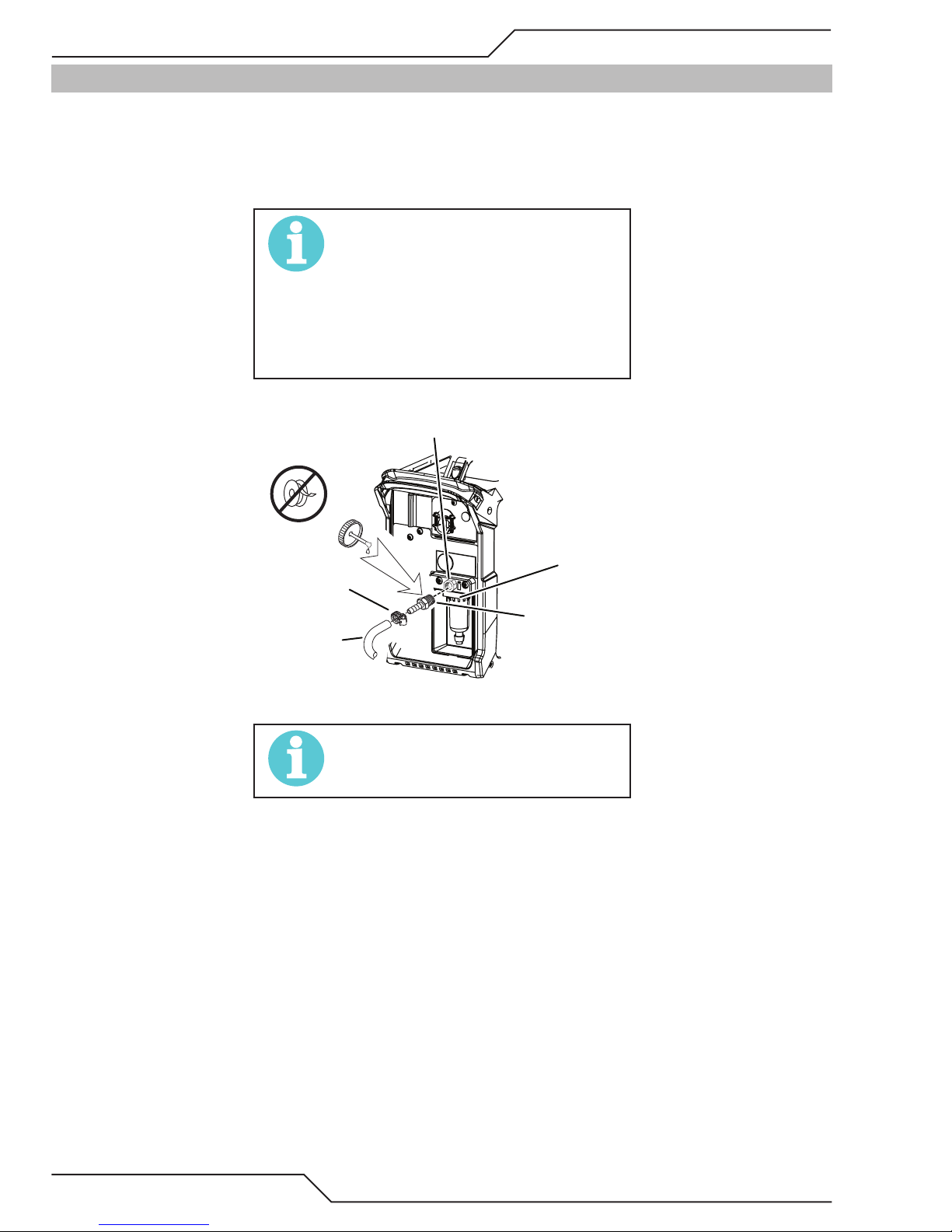
3.07 Gas Connections
Connecting Gas Supply to Unit
The connection is the same for compressed air or high pressure cylinders. Refer to the following two subsections
if an optional air line filter is to be installed.
1. Connect the air or argon line to the inlet port. The illustration shows typical fittings as an example.
NOTE!
For a secure seal, apply thread sealant to the tting threads, according to
manufacturer’s instructions. Do not
use Teon tape as a thread sealer, as
small particles of the tape may break
o and block the small air passages in
the torch.
1/4 NPT Inlet Port
Hose Clamp
Gas Supply
Hose
Filter
Assembly
3/8 barb to
1/4 NPT”
(6mm) Fitting
Air Connection to Inlet Port
NOTE!
Filter replacement part numbers can
be found in Section 6 of this manual
INSTALLATION Manual 0-5466
3-4
Page 29
A40i, A60i
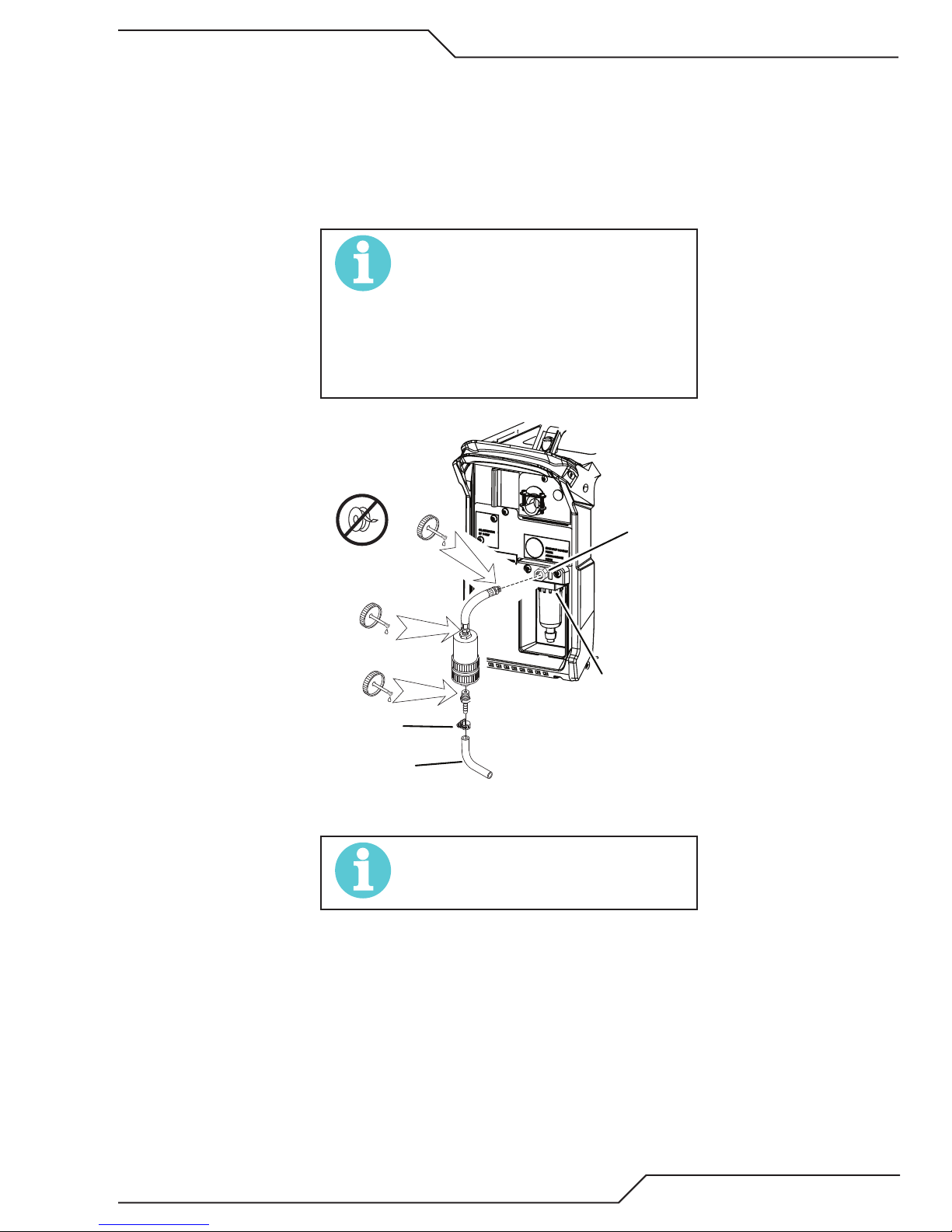
Installing Optional Single - Stage Air Filter
An optional filter kit is recommended for improved filtering with compressed air, to keep moisture and debris out
of the torch.
1. Attach the Single - Stage Filter Hose to the Inlet Port 1/4" NPT of the system filter.
2. Attach the Filter Assembly to the filter hose.
3. Connect the air line to the Filter using the 1/4" NPT. The illustration shows typical fittings as an example.
NOTE!
For a secure seal, apply thread sealant to the tting threads, according to
manufacturer’s instructions. Do not
use Teon tape as a thread sealer, as
small particles of the tape may break
o and block the small air passages in
the torch.
Hose Clamp
Gas Supply
Hose
Optional Single - Stage Filter Installation
System Filter
Assembly
Art # A-13261
NOTE!
Filter replacement part numbers can
be found in Section 6 of this manual
1/4 NPT
Inlet Port
Manual 0-5466 INSTALLATION
3-5
Page 30
A40i, A60i
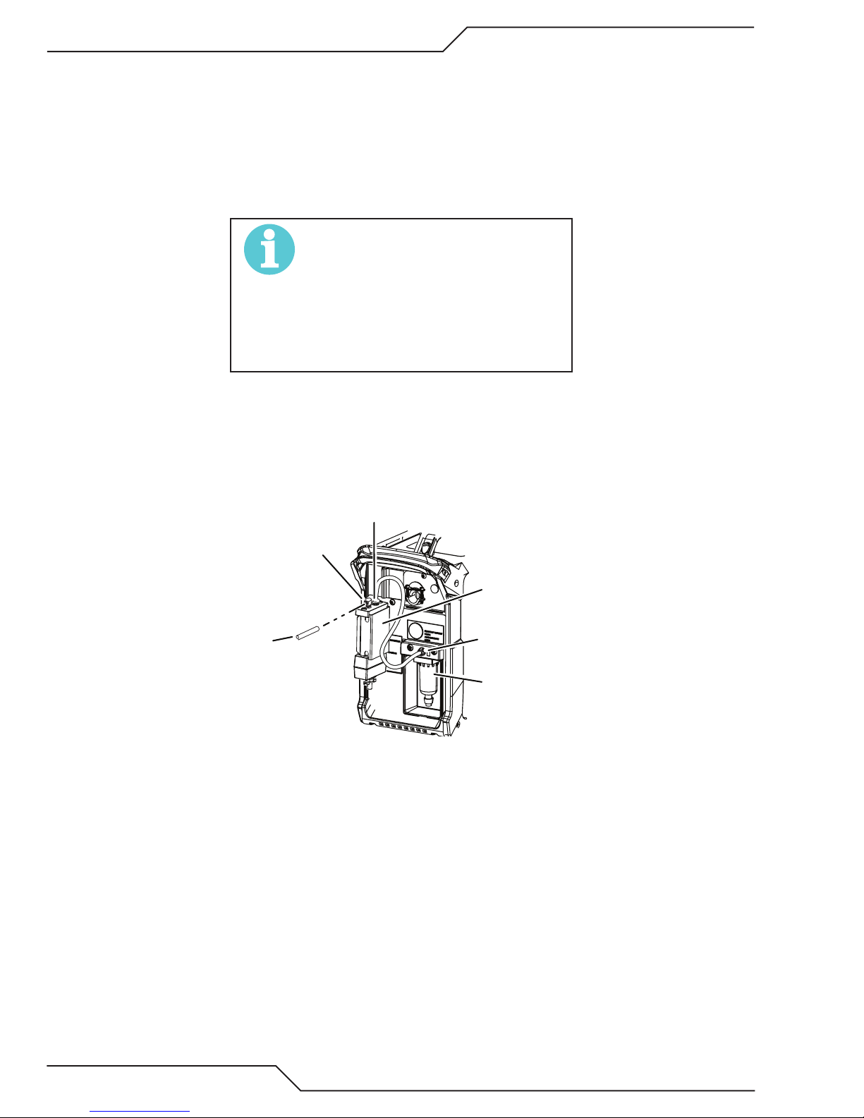
Installing Optional Two - Stage Air Filter Kit
This optional two - stage air line filter is also for use on compressed air shop systems. Filter removes moisture and
contaminants to at least 5 microns.
Connect the air supply as follows:
1. Attach the Two Stage Filter bracket to the back of the power supply with the screws supplied.
NOTE!
For a secure seal, apply thread sealant to the tting threads, according to
manufacturer’s instructions. Do not
use Teon tape as a thread sealer, as
small particles of the tape may break
o and block the small air passages in
the torch.
2. Connect the two stage filter outlet hose to the inlet port of the Regulator / Filter Assembly.
3. Use customer - supplied fittings to connect the air line to the Filter. A 5/16 (8mm) O.D. smooth tubing should
be used with the press in fitting.
2-Stage Filter
Inlet Port (IN)
5/16 (8mm)
O.D.
Gas
Supply Tubing
Art # A-13288
Optional Two - Stage Filter Installation
Outlet Port
(OUT)
Two Stage
Filter
Assembly
Air/Gas
Input
System Filter
Assembly
INSTALLATION Manual 0-5466
3-6
Page 31

A40i, A60i
NOTE!
Filter replacement part numbers can
be found in Section 6 of this manual
Using High Pressure Air Cylinders
When using high pressure air cylinders as the air supply:
1. Refer to the manufacturer’s specifications for installation and maintenance procedures for high pressure
regulators.
2. Examine the cylinder valves to be sure they are clean and free of oil, grease or any foreign material. Briefly
open each cylinder valve to blow out any dust which may be present.
3. The cylinder must be equipped with an adjustable high - pressure regulator capable of outlet pressures up
to 120 psi (8.3 bar) maximum and flows of least 300-500 scfh / 5 - 8.3 CFM (142-235 lpm).
4. Connect supply hose to the cylinder.
NOTE!
Pressure should be set at 120 psi (8.3
bar) at the high pressure cylinder
regulator.
3.08 Work Lead Connections
Connect the Work Lead to the power supply and the work piece.
1. Attache the Dinse type connection of the work lead to the power supply front panel as shown below. Push
in and turn clockwise to the right until tight.
2. Connect the work clamp to the workpiece or cutting table. The area must be free from oil, paint and rust.
Connect only to the main part of the work piece; do not connect to the part to be cut off.
3
2
Art# A-13249
1
Manual 0-5466 INSTALLATION
3-7
Page 32

A40i, A60i
This Page Intentionally Blank
INSTALLATION Manual 0-5466
3-8
Page 33

A40i, A60i
Wo
Art # A-08323_AB
Plasma
Divided
oltage
SECTION 3 TORCH:
INSTALLATION
3T.01 Torch Connections
If necessary, connect the torch to the Power Supply.
Connect only the Thermal Dynamics model SL60,
SL60QD™ or SL100 / Mechanical Torch to this power
supply. Maximum torch leads length is 100 feet / 30.5
m, including extensions.
WARNING
Disconnect primary power at the
source before connecting the torch.
1. Align the ATC male connector (on the torch lead)
with the female receptacle. Push the male connector into the female receptacle. The connectors
should push together with a small amount of
pressure.
2. Secure the connection by turning the locking nut
clockwise until it clicks. DO NOT use the locking
nut to pull the connection together. Do not use
tools to secure the connection.
3T.02 Setting Up Mechanical Torch
WARNING
Disconnect primary power at the
source before disassembling the torch
or torch leads.
The mechanical torch includes a positioning tube with
rack and pinch block assembly.
1. Mount the torch assembly on the cutting table.
2. To obtain a clean vertical cut, use a square to
align the torch perpendicular to the surface of
the workpiece.
Pinch Block
Assembly
Square
Art # A-13286
Connecting the Torch to the Power Supply
3. The system is ready for operation.
Check Air Quality
To test the quality of air:
1. Put the ON / OFF switch in the ON (Left) position.
2. Select SET mode.
rkpiece
A-02585
Mechanical Torch Set - Up
2
3. The proper torch parts (shield cup, tip, start cartridge, and electrode) must be installed for the
type of operation. Refer to Section "4T.01 Torc h
Parts Selection" on page 4T-1 for details.
1
Start / Stop
Signal
Arc
V
3. Place a welding filter lens in front of the torch
and turn ON the air. Do not start an arc!
Any oil or moisture in the air will be visible on the lens.
Manual 0-5466 INSTALLATION
Cutting Machine
OK to Move
3T-1
Page 34

A40i, A60i
This Page Intentionally Blank
INSTALLATION Manual 0-5466
3T-2
Page 35

SECTION 4 SYSTEM:
4.01 Front Panel Controls / Features
See Illustration for numbering Identification
2
3
4
5
6
7
8
9
10
11
A40i, A60i
OPERATION
1
16
14
15
13
12
17
18
Art # A-13250
1. Numeric Display
• Displays software revision at start up
• Displays amperage values (Factory default)
• Displays error codes
• Displays pre-set (preview) maintenance functions
2. AC Indicator
Steady light indicates power supply is ready for operation. Blinking light indicates the input voltage is outside of
operating range or internal fault.
3. DC Indicator
Indicator is ON when DC output circuit is active.
4. Latch/Lock
Indicator is ON when unit is in "Latch" mode.
Manual 0-5466 OPERATION
4-1
Page 36
A40i, A60i
5. Set Mode Indicator
Indicator is ON when unit is owing gas and pressure can be set.
6. Shield Cup In Place Indicator
Indicator is Blinking when any of the following are not in place or connected: Shield Cup, ATC leads or Quick Disconnect.
7. Gouge Mode Indicator
Indicator is ON when unit is in "Gouge" mode and all Cutting Indicators (#8) are illuminated.
8. Type of Cutting Indicator
Dierent segments will be illuminated to indicate dierent types of cutting.
• Gouging - All illuminated
• Normal Cutting and Latch Mode - Center indicator will be off.
• RAR (Rapid Auto Restart) Cutting - Every other indicator will be off.
• Marking - The two indicators to the far right will be off. The Gouge Mode will be selected and gas pressure
set below 20 lbs.
• Set Mode - All indicators will be off.
9. Fault Indicator
Indicator is ON when unit is in fault condition. See error codes appendix for fault light explanations. Flashing when active.
Factory default: O
10. EOL (End Of Life) Indicator
Indicator is normally o. It is also o during Drag Cutting.
When on it is to inform user that consumable failure is imminent
Active and/or operable in all cutting modes except Drag..
11. Over Temp Indicator
Indicator is normally OFF. Indicator is ON/FLASHING when internal temperature exceeds normal limits. Let the unit
cool before continuing operation.
OPERATION Manual 0-5466
4-2
Page 37

A40i, A60i
12. Gas Pressure Indicator
Indicator used to show low, optimal and high gas pressure. Torch type, lead length, cutting mode and amperage should
all be set prior to setting the gas pressure. (90 - 125 PSI / 6.2 - 8.6 bar)
One of 7 segments will always be on when unit is on. The gas bottle will be illuminated and ash during a gas pressure
fault. Bottle will ash when pressure is below a minimum threshold. Bottle will be on continuously when acceptable.
Factory default: One, or two segments and gas bottle will be illuminated depending on the gas pressure level. The
green indicator in the middle indicates the recommended pressure for the process (Amps, torch type, lead length).
Dierent processes have dierent optimum pressures.
Yellow indicates above or below optimum pressure and red indicates unacceptable pressure for good cutting. Each
LED represents 5 psi. Two adjacent LEDs will represent a value in between the two or 2.5 lb. pressure change..
13. Gas Pressure Selector
Rotate the lower knob to set the gas pressure.
14. Torch Type Indicator
Used for selecting one of the three torch options and torch length for each. SLV will be automatically detected.
Factory default: On, SL60 which includes SL60QD™ (Quick Disconnect)
Press and release the lower knob without rotating it to step through selection of torch type.
NOTE!
If you have gone past the desired setting, you will need to continue to step
through all the other torch types and lengths to get back to return to it..
15. Lead Length Indicator
Used for selecting torch lead length for each torch type ranging between 20’ and 100’ leads.
Factory default: On, 20’ or 25'
Press and release the lower knob without rotating it to step through selection of torch type followed by lead length.
Up to 35’ Lead (10.7 m)
Above 35' to 50’ Lead (15.2 m)
Above 50' to 75’ Lead (22.9 m)
Above 75' to 100’ Lead (30.5 m)
NOTE!
If you have gone past the desired setting, you will need to continue to step
through all the other torch types and lengths to get back to return to it..
Manual 0-5466 OPERATION
4-3
Page 38

A40i, A60i
16. Upper Knob - Amp and Mode Selector
Rotate knob to increase or decrease amperage. Indicator is ON when numeric display is showing amperage output.
Press and release knob without turning to step through the dierent Modes.
Factory default: On
Numeric display
17. Torch Quick Disconnect Receptacle
Torch Leads are connected here by aligning the connectors, pressing in and turning locking ring clockwise-to-the-right
to secure. Connection should only be snug with no tools used.
18. Work Lead Dinse type receptacle
Align Dinse type connector on work lead with receptacle, press in and turn clockwise to the right until tight.
4.02 Preparations for Operation
At the start of each operating session:
WARNING
Disconnect primary power at the
source before assembling or disassembling power supply, torch parts, or
torch and leads assemblies.
Torch Parts Selection
Check the torch for proper assembly and appropriate torch parts. The torch parts must correspond with the type of
operation, and with the amperage output of this Power Supply (60 amps maximum). Refer to Section 4T.07 and following for torch parts selection.
Torch Connection
Check that the torch is properly connected. Only Thermal Dynamics models SL60, SL60QD™ / Manual or SL100 / Mechanical Torches may be connected to this Power Supply. See Section 3T of this manual.
Check Primary Input Power Source
1. Check the power source for proper input voltage. Make sure the input power source meets the power requirements for the unit per Section 2, Specifications.
2. Connect the input power cable (or close the main disconnect switch) to supply power to the system.
Air or Argon Source
Ensure source meets requirements (refer to Section 2). Check connections and turn air or argon supply ON.
OPERATION Manual 0-5466
4-4
Page 39

A40i, A60i
Art # A-04509
Connect Work Cable
Clamp the work cable to the workpiece or cutting table. The area must be free from oil, paint and rust. Connect only
to the main part of the workpiece; do not connect to the part to be cut o.
Power ON
Place the Power Supply ON / OFF switch to the ON (right) position. AC indicator turns ON.
The Control Board performs several tests to determine the system is ready to operate. During the self-tests the digital
display rst shows
is an example of a production released code revision that may be displayed.
Next displayed is the “checksum” a combination of letters and numbers that are unique to the rmware revision. These
are used by service personal to determine if the rmware has been corrupted.
If there are no issues detected the output current setting will be displayed with the letter "A" to the right, showing the
output current setting. Should a problem be detected the fault code in the format Exxx will display and the “A” will not
be illuminated. Refer to Section 5.04 for fault code explanations.
Gas indicator turns ON if there is sucient gas pressure for power supply operation and the cooling fan
turns ON. (90 - 125 PSI / 6.2 - 8.6 bar)
(revision) followed by the rmware revision number which includes decimals. 1.1.0
NOTE!
Minimum pressure for power supply
operation is lower than minimum for
torch operation.
The cooling fan will turn ON as soon as the unit is turned ON. After a short amount of time the fan
switches to low speed. The fan will return to high speed as soon as the torch switch (Start Signal) is activated or if the unit is turned OFF, then turned ON again. If an over temperature condition occurs, the
fan will continue to run at high speed while the condition exists and for a five (5) minute period once
the condition is cleared.
Manual 0-5466 OPERATION
4-5
Page 40

A40i, A60i
Select Cutting Mode
1
2
Art # A-13251
1. Press and release the upper knob without turning to enter the mode selection menu. Place the system in
one of the four cutting modes available by pressing and releasing the knob until you reach the desired
mode.:
RUN
LATCH .
RAPID AUTO RESTART
GOUGE
SET/PURGE (gas flow only)
MARKING
2. After selecting the cutting mode, set the output current by turning the knob.
Set Torch Parameters
1. Press and release the bottom knob without rotating to enter the torch type and leads length selections.
OPERATION Manual 0-5466
4-6
Page 41

A40i, A60i
Set Operating Pressure
NOTE!
Before the gas pressure is set, the torch type, leads length,
type of cutting and amperage should all be set as they
will aect the pressures required. If any of those are
changed, the pressure should be checked again to make
sure it is optimized.
1. Gas pressure must be set in the cutting mode to be used, not in the SET/PURGE mode. Each mode may
require a different pressure for optimal cutting. (90 - 125 PSI / 6.2 - 8.6 bar)
2. Set the gas pressure/flow using the lower knob, 2. Changes will show on the Gas Pressure Interlock
The green indicator in the center is the ideal setting. Each indicator when lit separately is equal to 5 lbs. from
the segment next to it. Each will show 5, 10 or 15 lbs or more below or above the ideal. When two segments
are illuminated together then the change is half as much or 2.5 lbs.. The pressure settings will all be affected
by the other settings for torch, torch length and type of cutting and will require adjustments to the pressure
setting.
Cutting Operation
When the torch leaves the workpiece during cutting operations in the RUN mode, there is a brief delay in restarting the
pilot arc. With the system in the RAPID AUTO RESTART mode, when the torch leaves the workpiece the pilot arc restarts
instantly, and the cutting arc restarts instantly when the pilot arc contacts the workpiece. (Use the 'Rapid Auto Restart'
mode when cutting expanded metal or gratings, or trimming operations when an uninterrupted restart is desired).
With the system in the LATCH mode the main cutting arc will be maintained after the torch switch is released. To exit or
cancel the LATCH mode, press and release the trigger again or lift the torch from the cutting surface so the arc goes out.
Typical Cutting Speeds
Cutting speeds vary according to torch output amperage, the type of material being cut, and operator skill. Refer to
Section "4T.08 Recommended Cutting Speeds for Mechanized Torch With Exposed Tip" and following for greater details.
Output current setting or cutting speeds may be reduced to allow slower cutting when following a line, or using a
template or cutting guide while still producing cuts of excellent quality.
Postflow
Release the trigger to stop the cutting arc. Gas continues to ow for approximately 20 seconds. During post - ow, if
the user moves the trigger release to the rear and presses the trigger, the pilot arc starts. The main arc transfers to the
workpiece if the torch tip is within transfer distance to the workpiece.
Shutdown
Turn the ON / OFF switch to OFF, to the left as you face the unit from the rear. After a short delay all Power Supply indicators and fan shut OFF. Unplug the input power cord or disconnect input power. Power is removed from the system.
NOTE!
To maximize the longevity of the internal electronics,
allow the power supply to continue running (without
cutting) until the cooling fan speed changes to slow.. This
may take a few minutes
Manual 0-5466 OPERATION
4-7
Page 42

A40i, A60i
4.03 Marking
Gas Type
1. The first thing you will want to do is determine which type of gas to use. When marking, you will use either
air or argon and they both have their advantages and disadvantages. This chart helps to make the best choice.
MARKING
Advantage
Disadvantage
•Lower Cost
•Excellent process overall
•No or little slag on mild steel
•High heat input. Can be a problem
for thin material
•Edges may be jagged when used
on aluminum
•Wider markings and more dross
than argon
Air Argon
Marking Samples at 10 Amps and 0.100" / 2.5mm Stando.
Marking with Air:
•Low heat imput which reduces the
risk of deformation
•High contrast
•Higher cost than air.
•When heavy scoring is needed there
is more slag on mild steel
OPERATION Manual 0-5466
4-8
Page 43

Marking with Argon:
2. Place the proper consumables in the torch for marking.
A40i, A60i
Deflector
9-8241 9-8237 9-8225 9-8213 9-8215
Gas Used Amperage
Air 10 0.100 100 0 Heavy
Air 10 0.100 150 0 Medium
Air 10 0.100 200 0 Light
Argon 15 0.100 100 0 Heavy
Argon 15 0.100 150 0 Medium
Argon 15 0.100 200 0 Light
Standard Shield Cup
Maximum Life Shield Cup
Torch Working Height
(in)
Tip
Travel Speed Pierce Delay
(ipm) (sec)
Starter Cartridge
Heavy Duty Starter
Cartridge
Electrode
Marking Density
3. Set the power supply mode to Marking.
4. Set the current level to less than 20 amps.
Begin marking.
Manual 0-5466 OPERATION
4-9
Page 44

A40i, A60i
Types of Marking
Light Marking:
This will consist of lines that are clean, thin and with very little depth and no slag. This type of marking can usually
be removed with secondary operations and are not as long lasting.
Heavy Marking/Scoring:
This type of marking will have deeper heavier lines that are long lasting. There can be a little slag associated with
this type of marking.
Dimple Marking:
This consists of a series of dots or small circles to create lines. The look of the mark will vary depending on amperage, gas and dwell time.
OPERATION Manual 0-5466
4-10
Page 45
SECTION 4 TORCH:
Standoff Distance
Straight Arc
Trailing Arc
Leading Arc
Direction of Torch Travel
A-02586
OPERATION
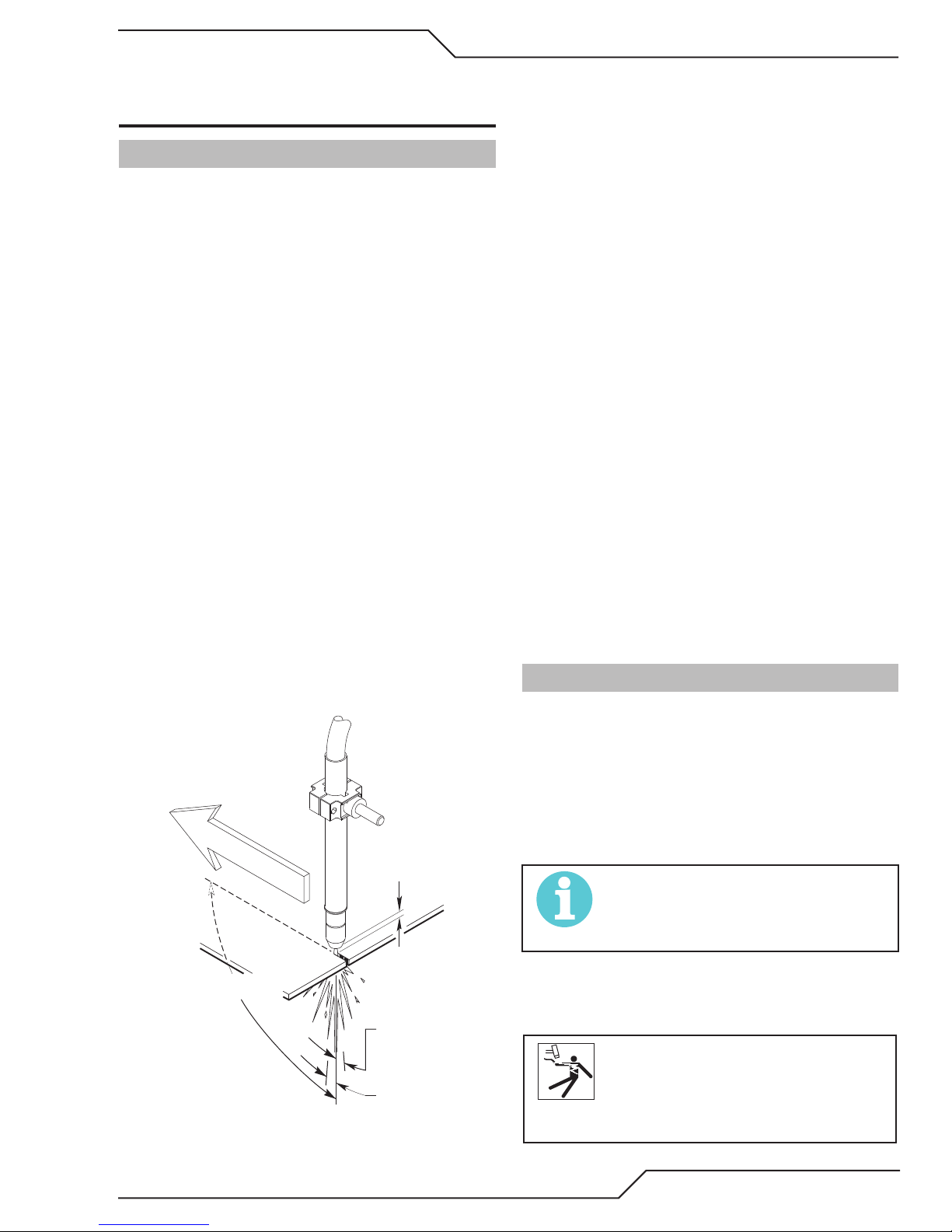
4T.01 Machine and Automated Torch
Operation
Cutting With Machine or Automated Torch
These torches are activated by remote control pendant or by a remote interface device such as CNC.
1. To start a cut at the plate edge, position the center
of the torch along the edge of the plate.
A40i, A60i
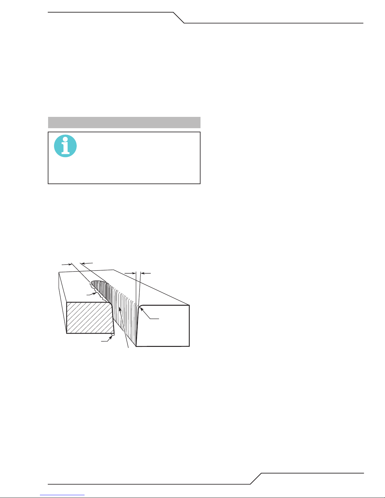
For optimum smooth surface quality, the travel
speed should be adjusted so that only the leading
edge of the arc column produces the cut. If the travel
speed is too slow, a rough cut will be produced as
the arc moves from side to side in search of metal
for transfer.
Travel speed also affects the bevel angle of a cut.
When cutting in a circle or around a corner, slowing
down the travel speed will result in a squarer cut.
The power source output should be reduced also.
Refer to the appropriate Control Module Operating
Manual for any Corner Slowdown adjustments that
may be required.
Travel Speed
Proper travel speed is indicated by the trail of the
arc which is seen below the plate. The arc can be
one of the following:
1. Straight Arc
A straight arc is perpendicular to the workpiece
surface. This arc is generally recommended
for the best cut using air plasma on stainless or
aluminum.
2. Leading Arc
The leading arc is directed in the same direction
as torch travel. A five degree leading arc is generally recommended for air plasma on mild steel.
3. Trailing Arc
The trailing arc is directed in the opposite direction as torch travel.
Piercing With Machine or Automated Torch
To pierce, the arc should be started with the torch
positioned as high as possible above the plate while
allowing the arc to transfer and pierce. This standoff
helps avoid having molten metal blow back onto the
front end of the torch.
When operating with a cutting machine, a pierce or
dwell time is required. Torch travel should not be
enabled until the arc penetrates the bottom of the
plate. As motion begins, torch standoff should be
reduced to the recommended 1/8 - 1/4 inch (3-6
mm) distance for optimum speed and cut quality.
Clean spatter and scale from the shield cup and the
tip as soon as possible. Spraying or dipping the
shield cup in anti - spatter compound will minimize
the amount of scale which adheres to it.
4T.02 Automation Torch Parts Selection
Check the torch for proper consumable parts. The
parts supplied in the torch may not be correct for the
operator’s chosen amperage level. The torch parts
must correspond with the type of operation.
Automation and Machine Torch Operation
Manual 0-5466 OPERATION
Torch parts:
Shield Cup, Cutting Tip, Electrode and Starter
Cartridge
NOTE!
Refer to Section 4T.07 and following for
additional information on torch parts.
Change the torch parts for a different operation as follows:
WARNING
Disconnect primary power at the
source before assembling or disassembling torch parts, or torch and leads
assemblies.
4T-1
Page 46
A40i, A60i
A-03510_AB
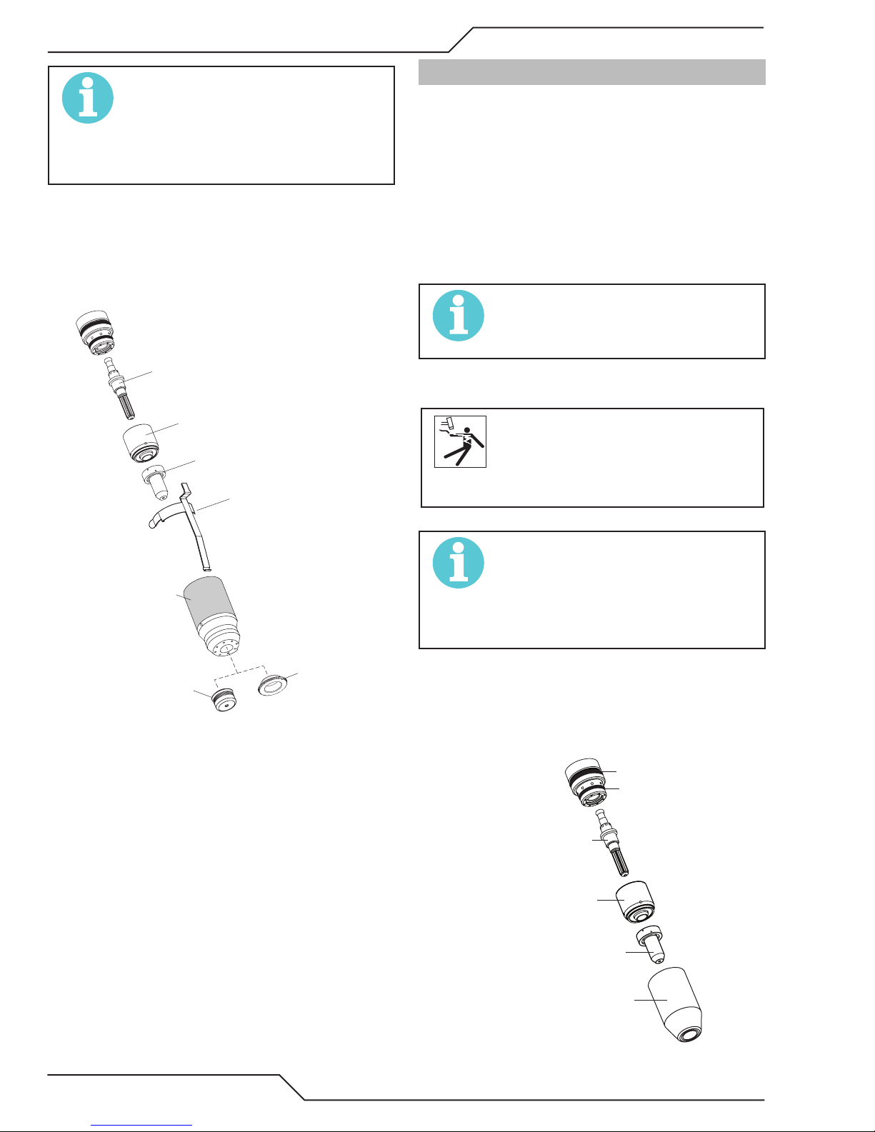
NOTE!
The shield cup holds the tip and start
cartridge in place. Position the torch
with the shield cup facing upward to
keep these parts from falling out when
the cup is removed.
1. If attached, remove the ohmic clip then unscrew
and remove the shield cup assembly from the
torch head. Wipe it clean or replace if damaged
2. Remove the Electrode by pulling it straight out
of the Torch Head.
Torch Head
Electrode
Start Cartridge
Tip
Art # A-04173_AB
Ohmic Clip
(If installed)
4T.03 Machine and Hand Torch Parts
Selection
Depending on the type of operation to be done determines the torch parts to be used.
Type of operation:
Drag cutting, standoff cutting or gouging
Torch parts:
Shield Cup, Cutting Tip, Electrode and Starter
Cartridge
NOTE!
Refer to Section 4T.08 and following for
additional information on torch parts..
Change the torch parts for a different operation as follows:
WARNING
Disconnect primary power at the
source before assembling or disassembling torch parts, or torch and leads
assemblies.
Shield Cup Body
Deflector
Shield Cap
Automation Torch Parts
3. Install the replacement Electrode by pushing it
straight into the torch head until it clicks.
4. Install the starter cartridge and desired tip for
the operation into the torch head.
5. Hand tighten the shield cup assembly until it
is seated on the torch head. If resistance is felt
when installing the cup, check the threads before
proceeding
6. If used, attach the ohmic clip to the shield cup.
NOTE!
The shield cup holds the tip and start
cartridge in place. Position the torch
with the shield cup facing upward to
keep these parts from falling out when
the cup is removed.
1. Unscrew and remove the shield cup assembly
from the torch head.
2. Remove the Electrode by pulling it straight out
of the Torch Head.
Large O-Ring
Torch Head
Electrode
Start Cartridge
Small O-Ring
Tip
4T-2
OPERATION Manual 0-5466
Shield Cup
Torch Parts (Drag Shield Cap & Shield Cup Body
Page 47
Shown)
Kerf Width
Cut Surface
Bevel Angle
Top Edge
Rounding
Cut Surface
Drag Lines
Dross
Build-Up
Top
Spatter
A-00007
A40i, A60i
Cut Quality Characteristics
3. Install the replacement Electrode by pushing it
straight into the torch head until it clicks.
4. Install the starter cartridge and desired tip for
the operation into the torch head.
5. Hand tighten the shield cup assembly until it
is seated on the torch head. If resistance is felt
when installing the cup, check the threads before
proceeding.
4T.04 Cut Quality
NOTE!
Cut quality depends heavily on setup
and parameters such as torch stando,
alignment with the workpiece, cutting
speed, gas pressures, and operator
ability.
Cut quality requirements differ depending on application. For instance, nitride build - up and bevel angle
may be major factors when the surface will be welded
after cutting. Dross - free cutting is important when finish cut quality is desired to avoid a secondary cleaning
operation. The following cut quality characteristics are
illustrated in the following figure:
Cut Surface
The desired or specified condition (smooth or rough)
of the face of the cut.
Nitride Build - Up
Nitride deposits can be left on the surface of the cut
when nitrogen is present in the plasma gas stream.
These buildups may create difficulties if the material
is to be welded after the cutting process.
Bevel Angle
The angle between the surface of the cut edge and
a plane perpendicular to the surface of the plate.
A perfectly perpendicular cut would result in a 0°
bevel angle.
Top - Edge Rounding
Rounding on the top edge of a cut due to wearing
from the initial contact of the plasma arc on the
workpiece.
Bottom Dross Buildup
Molten material which is not blown out of the cut
area and resolidifies on the plate. Excessive dross
may require secondary cleanup operations after
cutting.
Kerf Width
The width of the cut (or the width of material removed during the cut).
Manual 0-5466 OPERATION
4T-3
Page 48

A40i, A60i
!
Right Side
Cut Angle
Left Side
Cut Angle
A-00512
Top Spatter (Dross)
Top spatter or dross on the top of the cut caused by
slow travel speed, excess cutting height, or cutting
tip whose orifice has become elongated.
4T.05 General Cutting Information
WARNING
Disconnect primary power at the
source before assembling or disassembling the power supply, torch parts, or
torch and leads assemblies.
Frequently review the Important
Safety Precautions at the front of
this manual. Be sure the operator is
equipped with proper gloves, clothing, eye and ear protection. Make sure
no part of the operator’s body comes
into contact with the workpiece while
the torch is activated.
Edge Starting
For edge starts, hold the torch perpendicular to the
workpiece with the front of the tip near (not touching) the edge of the workpiece at the point where
the cut is to start. When starting at the edge of the
plate, do not pause at the edge and force the arc to
"reach" for the edge of the metal. Establish the cutting arc as quickly as possible.
Direction of Cut
In the torches, the plasma gas stream swirls as it
leaves the torch to maintain a smooth column of
gas. This swirl effect results in one side of a cut being more square than the other. Viewed along the
direction of travel, the right side of the cut is more
square than the left.
CAUTION
Sparks from the cutting process can
cause damage to coated, painted, and
other surfaces such as glass, plastic and
metal.
NOTE!
ForHandle torch leads with care and
protect them from damage..
Piloting
Piloting is harder on parts life than actual cutting
because the pilot arc is directed from the electrode
to the tip rather than to a workpiece. Whenever
possible, avoid excessive pilot arc time to improve
parts life.
Torch Standoff
Improper standoff (the distance between the torch
tip and workpiece) can adversely affect tip life as
well as shield cup life. Standoff may also significantly affect the bevel angle. Reducing standoff will
generally result in a more square cut.
Side Characteristics Of Cut
To make a square - edged cut along an inside
diameter of a circle, the torch should move counterclockwise around the circle. To keep the square
edge along an outside diameter cut, the torch should
travel in a clockwise direction.
Dross
When dross is present on carbon steel, it is commonly referred to as either “high speed, slow speed,
or top dross”. Dross present on top of the plate is
normally caused by too great a torch to plate distance. "Top dross" is normally very easy to remove
and can often be wiped off with a welding glove.
"Slow speed dross" is normally present on the bottom edge of the plate. It can vary from a light to
4T-4
OPERATION Manual 0-5466
Page 49

heavy bead, but does not adhere tightly to the cut
A-00024_AB
Shield Cup
Torch
Standoff Distance
1/8" - 3/8" (3 - 9mm)
edge, and can be easily scraped off. "High speed
dross" usually forms a narrow bead along the bottom
of the cut edge and is very difficult to remove. When
cutting a troublesome steel, it is sometimes useful
to reduce the cutting speed to produce "slow speed
dross". Any resultant cleanup can be accomplished
by scraping, not grinding.
4T.06 Hand Torch Operation
Standoff Cutting With Hand Torch
NOTE!
For best performance and parts life, always use the correct parts for the type
of operation.
1. The torch can be comfortably held in one hand
or steadied with two hands. Position the hand to
press the Trigger on the torch handle. With the
hand torch, the hand may be positioned close to
the torch head for maximum control or near the
back end for maximum heat protection. Choose
the holding technique that feels most comfortable
and allows good control and movement.
A40i, A60i
Standoff Distance
3. Hold the torch away from your body.
4. Slide the trigger release toward the back of the
torch handle while simultaneously squeezing the
trigger. The pilot arc will start.
NOTE!
The tip should never come in contact
with the workpiece except during drag
cutting operations.
2. Depending on the cutting operation, do one of
the following:
a. For edge starts, hold the torch perpendicular
to the workpiece with the front of the tip on
the edge of the workpiece at the point where
the cut is to start.
b. For stando cuing, hold the torch 1/8 - 3/8
in (3-9 mm) from the workpiece as shown
below.
Trigger
Trigger Release
Art # A-13150
5. Bring the torch within transfer distance to the
work. The main arc will transfer to the work,
and the pilot arc will shut off.
NOTE!
The gas preow and postow are a
characteristic of the power supply and
not a function of the torch.
Manual 0-5466 OPERATION
4T-5
Page 50

A40i, A60i
3
4
Art # A-03383
Tr igger
2
1
Tr igger Release
Art # A-04034
A-03539
6. Cut as usual. Simply release the trigger assembly
to stop cutting.
7. Follow normal recommended cutting practices as
provided in the power supply operator's manual.
Shield Cup
Standoff Guide
Torch Tip
Workpiece
Shield Cup With Straight Edge
The drag shield cup can be used with a non conductive straight edge to make straight cuts by hand.
WARNING
The straight edge must be non - conductive.
NOTE!
When the shield cup is properly installed, there is a slight gap between
the shield cup and the torch handle.
Gas vents through this gap as part of
normal operation. Do not attempt to
force the shield cup to close this gap.
Forcing the shield cup against the
torch head or torch handle can damage components.
8. For a consistent standoff height from the workpiece, install the standoff guide by sliding it onto
the torch shield cup. Install the guide with the
legs at the sides of the shield cup body to maintain good visibility of the cutting arc. During
operation, position the legs of the standoff guide
against the workpiece.
Non-Conductive
Straight Edge
Cutting Guide
Using Drag Shield Cup With Straight Edge
The crown shield cup functions best when cutting
3/16 inch (4.7 mm) solid metal with relatively
smooth surface.
Drag Cutting With a Hand Torch
Drag cutting works best on metal 1/4" (6 mm) thick
or less.
NOTE!
For best performance and parts life, always use the correct parts for the type
of operation.
4T-6
OPERATION Manual 0-5466
Page 51

1. Install the drag cutting tip and set the output
t # A-03383
Tr igger
current.
2. The torch can be comfortably held in one hand
or steadied with two hands. Position the hand to
press the Trigger on the torch handle. With the
hand torch, the hand may be positioned close to
the torch head for maximum control or near the
back end for maximum heat protection. Choose
the holding technique that feels most comfortable
and allows good control and movement.
4. Keep the torch in contact with the workpiece
during the cutting cycle.
5. Hold the torch away from your body.
6. Slide the trigger release toward the back of the
torch handle while simultaneously squeezing the
trigger. The pilot arc will start.
Trigger
A40i, A60i
9. Follow normal recommended cutting practices as
provided in the power supply operator's manual.
NOTE!
When the shield cup is properly installed, there is a slight gap between
the shield cup and the torch handle.
Gas vents through this gap as part of
normal operation. Do not attempt to
force the shield cup to close this gap.
Forcing the shield cup against the
torch head or torch handle can damage components.
Piercing With Hand Torch
1. The torch can be comfortably held in one hand
or steadied with two hands. Position the hand to
press the Trigger on the torch handle. With the
hand torch, the hand may be positioned close to
the torch head for maximum control or near the
back end for maximum heat protection. Choose
the technique that feels most comfortable and
allows good control and movement.
Trigger Release
Art # A-13150
7. Bring the torch within transfer distance to the
work. The main arc will transfer to the work,
and the pilot arc will shut off.
NOTE!
The gas preow and postow are a
characteristic of the power supply and
not a function of the torch.
1
2
Tr igger Release
3
NOTE!
The tip should never come in contact
with the workpiece except during drag
cutting operations.
2. Angle the torch slightly to direct blowback particles
away from the torch tip (and operator) rather than
directly back into it until the pierce is complete.
3. In a portion of the unwanted metal start the pierce off
the cutting line and then continue the cut onto the line.
Hold the torch perpendicular to the workpiece after the
pierce is complete.
4. Hold the torch away from your body.
5. Slide the trigger release toward the back of the torch
handle while simultaneously squeezing the trigger. The
pilot arc will start.
Trigger
4
8. Cut as usual. Simply release the trigger assembly
to stop cutting.
Manual 0-5466 OPERATION
Trigger Release
Art # A-13150
Ar
4T-7
Page 52

A40i, A60i
!
!
6. Bring the torch within transfer distance to the
work. The main arc will transfer to the work,
and the pilot arc will shut off.
NOTE!
The gas preow and postow are a
characteristic of the power supply and
not a function of the torch.
NOTE!
The gas preow and postow are a
characteristic of the power supply and
not a function of the torch.
When the shield cup is properly installed, there is a slight gap between
the shield cup and the torch handle.
Gas vents through this gap as part of
normal operation. Do not attempt to
force the shield cup to close this gap.
Forcing the shield cup against the
torch head or torch handle can damage components.
7. Clean spatter and scale from the shield cup and the tip
as soon as possible. Spraying the shield cup in anti spatter compound will minimize the amount of scale
which adheres to it.
Cutting speed depends on material, thickness, and the
operator’s ability to accurately follow the desired cut
line. The following factors may have an impact on system performance:
• Torch parts wear
• Air quality
• Line voltage fluctuations
• Torch standoff height
• Proper work cable connection
4T.07 Gouging
WARNING
Be sure the operator is equipped with
proper gloves, clothing, eye and ear
protection and that all safety precautions at the front of this manual have
been followed. Make sure no part of
the operator’s body comes in contact
with the workpiece when the torch is
activated.
Disconnect primary power to the system before disassembling the torch,
leads, or power supply.
CAUTION
!
Gouging Parameters
Gouging performance depends on parameters
such as torch travel speed, current level, lead angle
(the angle between the torch and workpiece), and
the distance between the torch tip and workpiece
(standoff).
Sparks from the cutting process can
cause damage to coated, painted, and
other surfaces such as glass, plastic and
metal.
Check torch parts. The torch parts
must correspond with the type of
operation. Refer to Section 4T.09, Torch
Parts Selection.
CAUTION
Touching the torch tip or shield cup to
the work surface will cause excessive
parts wear..
Torch Travel Speed
NOTE!
Refer to Appendix Pages for additional
information as related to the Power
Supply used..
Optimum torch travel speed is dependent on current
setting, lead angle, and mode of operation (hand or
machine torch).
Current Setting
Current settings depend on torch travel speed,
mode of operation (hand or machine torch), and the
amount of material to be removed.
4T-8
OPERATION Manual 0-5466
Page 53

A40i, A60i
35°
Workpiece
Torch Head
Standoff Height
A-00941_AB
Lead Angle
The angle between the torch and workpiece depends on the output current setting and torch travel speed. The
recommended lead angle is 35°. At a lead angle greater than 45° the molten metal will not be blown out of the
gouge and may be blown back onto the torch. If the lead angle is too small (less than 35°), less material may be
removed, requiring more passes. In some applications, such as removing welds or working with light metal,
this may be desirable.
Gouging Angle and Standoff Distance
Standoff Distance
The tip to work distance affects gouge quality and depth. Standoff distance of 1/8 - 1/4 inch (3 - 6 mm) allows
for smooth, consistent metal removal. Smaller standoff distances may result in a severance cut rather than a
gouge. Standoff distances greater than 1/4 inch (6 mm) may result in minimal metal removal or loss of transferred main arc.
Slag Buildup
This Page Intentionally Blank
Slag generated by gouging on materials such as carbon and stainless steels, nickels, and alloyed steels, can be
removed easily in most cases. Slag does not obstruct the gouging process if it accumulates to the side of the
gouge path. However, slag build - up can cause inconsistencies and irregular metal removal if large amounts of
material build up in front of the arc. The build - up is most often a result of improper travel speed, lead angle,
or standoff height.
Manual 0-5466 OPERATION
4T-9
Page 54
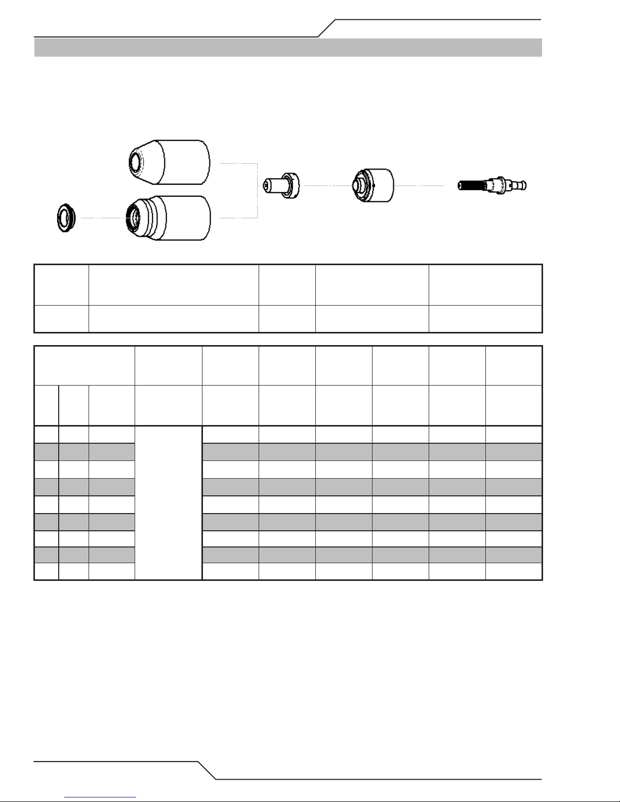
A40i, A60i
4T.08 Recommended Cutting Speeds for Machine and Automated Torches With Exposed Tip
Mild Steel
40A
Air Plasma / Air Shield
Deector
9-8243
Material
Thickness
(GA)
(in) inch
20
16
14
12
10
3/16 0.188 111 0.14 55 0.18 0.4 0.06
1/4 0.250 117 0.14 40 0.18 0.5 0.07
3/8 0.375 119 0.14 25 0.18 1.2 0.07
1/2 0.500 120 0.14 15 0.2 2.0 0.07
Standard Shield Cup
Maximum Life Shield Cup
9-8218
9-8237
Gas Pressure
(Air)
PSI
(torch lead
length)
0.036
0.060 103 0.14 140 0.18 0.0 0.05
0.075 105 0.14 120 0.18 0.1 0.06
0.105 108 0.14 80 0.18 0.2 0.06
0.135 110 0.14 60 0.18 0.3 0.06
70 (25')
75 (50')
Arc V oltage
Volts
101 0.14 160 0.18 0.0 0.05
Tip
9-8208
Torch
Working
Height
(in)
Starter Cartridge
Heavy Duty Starter
Cartridge
9-8213
9-8277
Initial
Travel Speed
(ipm) (in) (sec) (in)
Piercing
Height
Pierce Delay
Electrode
9-8232
Kerf Width
@ Rec.
Speed
4T-10
OPERATION Manual 0-5466
Page 55

A40i, A60i
Material
Thickness
(mm)
1
2
3
4
5
6
8
10
12
Gas Pressure
(Air)
Bar
(torch lead
length)
4.8 (7.6m)
5.2 (15.2m)
BOLD TYPE indicates maximum piercing parameters.
Torch
Arc Voltage
Volts (mm) (mm/min) (mm) (sec) (mm)
101
105 3.6 2920 4.6 0.1 1.4
109 3.6 1810 4.6 0.3 1.5
110 3.6 1470 4.6 0.3 1.6
112 3.6 1345 4.6 0.4 1.6
116 3.6 1100 4.6 0.5 1.7
118 3.6 815 4.6 1.0 1.7
119 3.6 595 4.6 1.5 1.8
120 3.6 435 5.1 2.0 1.8
Working
Height
3.6
Travel Speed
3990 4.6 0.0 1.1
Initial
Piercing
Height
Pierce Delay
Kerf Width
@ Rec.
Speed
Manual 0-5466 OPERATION
4T-11
Page 56
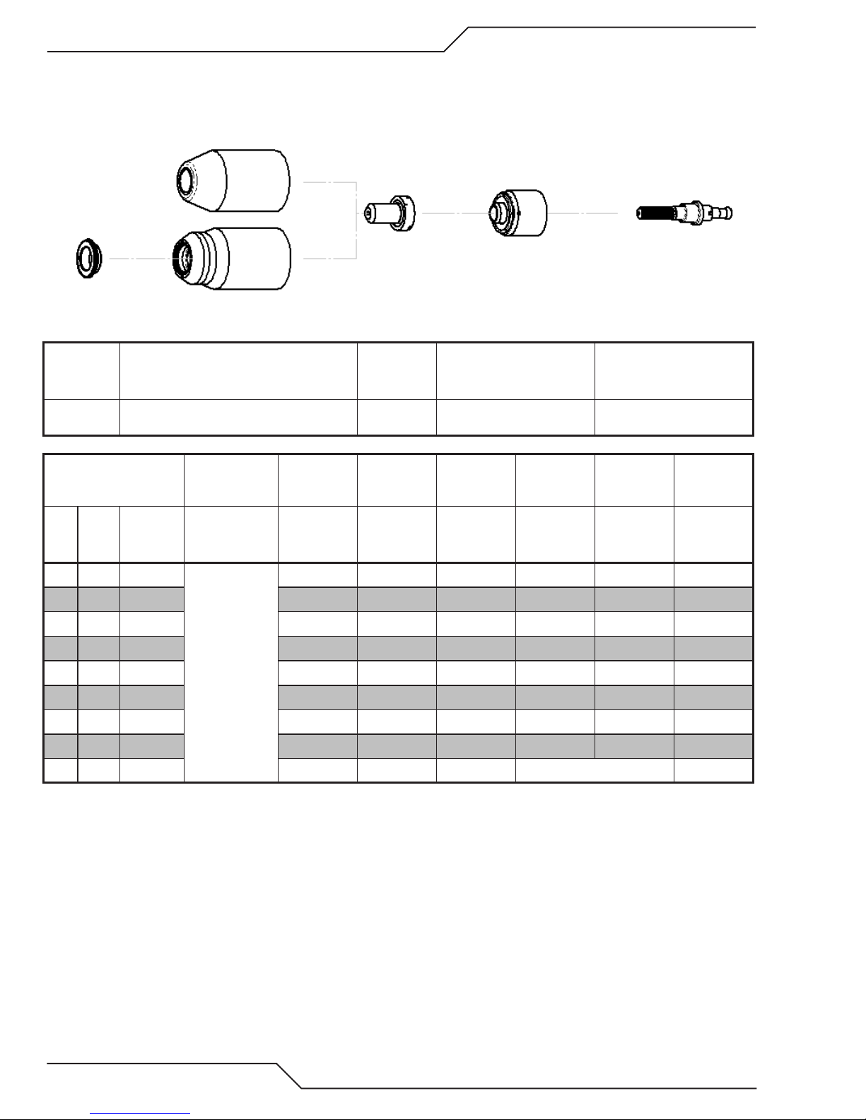
A40i, A60i
Stainless Steel
40A
Air Plasma / Air Shield
Deector
9-8243
Material
Thickness
(GA)
(in) inch
18
16
14
12
10
3/16 0.188 110 0.19 30 0.20 0.40 0.07
1/4 0.250 120 0.19 18 0.20 0.50 0.08
3/8 0.375 126 0.19 10 0.20 2.00 0.08
Standard Shield Cup
Maximum Life Shield Cup
9-8218
9-8237
Gas Pressure
(Air)
PSI
(torch lead
length)
0.050
0.063 100 0.19 50 0.20 0.00 0.07
0.078 105 0.19 45 0.20 0.10 0.07
0.109 110 0.19 40 0.20 0.20 0.07
0.141 108 0.19 35 0.20 0.30 0.07
75 (25')
80 (50')
Arc V oltage
Volts
110 0.19 60 0.20 0.00 0.07
Tip
9-8208
Torch
Working
Height
(in)
Starter Cartridge
Heavy Duty Starter
Cartridge
9-8213
9-8277
Initial
Travel Speed
(ipm) (in) (sec) (in)
Piercing
Height
Pierce Delay
Electrode
9-8232
Kerf Width
@ Rec.
Speed
1/2 0.500 118 0.19 8 Edge start 0.09
4T-12
OPERATION Manual 0-5466
Page 57

A40i, A60i
Material
Thickness
(mm)
1
2
3
4
5
6
8
10
12 120 4.8 215 Edge Start 2.2
BOLD TYPE indicates maximum piercing parameters. BOLD ITALIC indicates edge starts only.
Gas Pressure
(Air)
Bar
(torch lead
length)
5.2 (7.6)
5.5 (15.2)
Arc Voltage
Volts (mm) (mm/min) (mm) (sec) (mm)
112
105 4.8 1140 5.1 0.1 1.8
109 4.8 980 5.1 0.2 1.8
109 4.8 845 5.1 0.3 1.8
111 4.8 715 5.1 0.4 1.8
118 4.8 525 5.1 0.5 2.0
123 4.8 350 5.1 1.5 2.0
125 4.8 245 5.1 2.0 2.0
Torch
Working
Height
4.8
Travel Speed
1670 4.8 0.0 1.7
Initial
Piercing
Height
Pierce Delay
Kerf Width
@ Rec.
Speed
Manual 0-5466 OPERATION
4T-13
Page 58

A40i, A60i
Aluminum
40A
Air Plasma / Air Shield
Deector
9-8243
Material
Thickness
(GA)
(in) inch
20
16
12
11
9
3/16 0.188 116 0.18 75 0.18 0.5 0.07
1/4 0.250 128 0.18 30 0.18 1.0 0.08
3/8 0.375 150 0.18 10 Edge Start 0.09
Standard Shield Cup
Maximum Life Shield Cup
9-8218
9-8237
Gas Pressure
(Air)
PSI
(torch lead
length)
0.040
0.063 97 0.16 170 0.16 0.0 0.06
0.097 113 0.16 100 0.16 0.2 0.07
0.125 115 0.16 90 0.18 0.3 0.07
0.160 113 0.18 85 0.18 0.4 0.07
70 (25')
75 (50')
Arc V oltage
Volts
95 0.16 300 0.16 0.0 0.06
Tip
9-8208
Torch
Working
Height
(in)
Starter Cartridge
Heavy Duty Starter
Cartridge
9-8213
9-8277
Initial
Travel Speed
(ipm) (in) (sec) (in)
Piercing
Height
Pierce Delay
Electrode
9-8232
Kerf Width
@ Rec.
Speed
4T-14
OPERATION Manual 0-5466
Page 59

A40i, A60i
Material
Thickness
(mm)
1.0
2.0 104 4.1 3500 4.1 0.2
3.0 115 4.1 2350 4.6 0.3
4.0 113 4.6 2170 4.6 0.4
5.0 118 4.6 1740 4.6 0.5
6.0 125 4.6 1015 4.6 0.8
8.0 139 4.6 500 Edge Start
10.0 153 4.6 180 Edge Start
BOLD TYPE indicates maximum piercing parameters. BOLD ITALIC indicates edge starts only.
Gas Pressure
(Air)
Bar
(torch lead
length)
4.8 (7.6m)
5.2 (15.2m)
Arc Voltage
Volts (mm) (mm/min) (mm) (sec) (mm)
95 4.1 7620 4.1 0.0
Torch
Working
Height
Travel Speed
Initial
Piercing
Height
Pierce Delay
Kerf Width
@ Rec.
Speed
1.5
1.6
1.7
1.7
1.8
1.9
2.0
2.2
Manual 0-5466 OPERATION
4T-15
Page 60
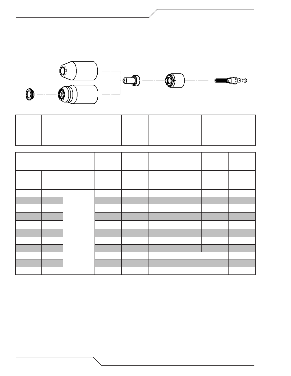
A40i, A60i
Mild Steel
60A
Air Plasma / Air Shield
Deector
9-8243
Material
Thickness
(GA)
(in) inch
16
14
11
10
3/16 0.188 121 0.19 100 0.19 0.20 0.08
1/4 0.250 122 0.19 80 0.19 0.30 0.08
3/8 0.375 124 0.19 50 0.19 0.50 0.09
1/2 0.500 132 0.19 26 0.19 0.75 0.10
5/8 0.625 135 0.19 19 Edge Start 0.10
3/4 0.750 136 0.19 14
1 1.000 150 0.19 6 Edge Start 0.11
Standard Shield Cup
Maximum Life Shield Cup
9-8218
9-8237
Gas Pressure
(Air)
PSI
(torch lead
length)
0.060
0.075 120 0.19 285 0.19 0.10 0.08
0.120 118 0.19 180 0.19 0.10 0.08
0.135 119 0.19 176 0.19 0.10 0.07
85 (25')
90 (50')
Arc V oltage
Volts
118 0.19 290 0.19 0.00 0.08
Tip
9-8210
Torch
Working
Height
(in)
Starter Cartridge
Heavy Duty Starter
Cartridge
9-8213
9-8277
Initial
Travel Speed
(ipm) (in) (sec) (in)
Piercing
Height
Pierce Delay
Edge Start 0.08
Electrode
9-8232
Kerf Width
@ Rec.
Speed
4T-16
OPERATION Manual 0-5466
Page 61
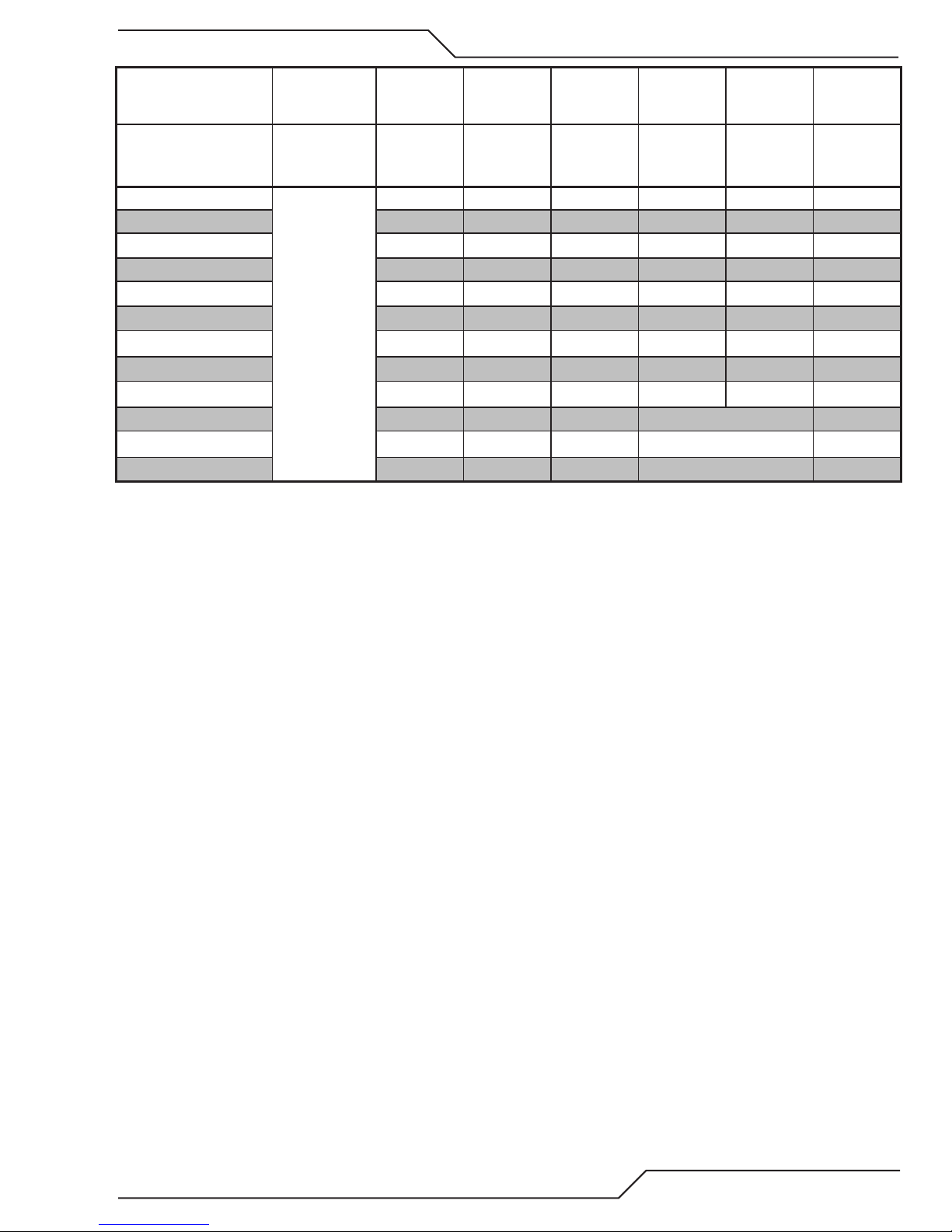
A40i, A60i
Material
Thickness
(mm)
1
2
3
4
5
6
8
10
12
15 134 4.8 530 Edge Start 2.4
20 138 4.8 325 Edge Start 2.2
25 149 4.8 165 Edge Start 2.7
BOLD TYPE indicates maximum piercing parameters. BOLD ITALIC indicates edge starts only.
Gas Pressure
(Air)
Bar
(torch lead
length)
5.9 (7.6m)
6.2 (15.2m)
Arc Voltage
Volts (mm) (mm/min) (mm) (sec) (mm)
115
120 4.8 7015 4.0 0.10 1.9
118 4.8 4570 4.8 0.10 0.1
120 4.8 3650 4.8 0.20 1.9
121 4.8 2465 4.8 0.20 2.1
122 4.8 2145 4.8 0.30 2.0
123 4.8 1635 4.8 0.40 2.2
125 4.8 1180 4.8 0.60 2.4
130 4.8 795 4.8 0.75 2.4
Torch
Working
Height
4.8
Travel Speed
7540 4.8 0 2.1
Initial
Piercing
Height
Pierce Delay
Kerf Width
@ Rec.
Speed
Manual 0-5466 OPERATION
4T-17
Page 62

A40i, A60i
Stainless Steel
60A
Air Plasma / Air Shield
Deector
9-8243
Material
Thickness
(GA)
(in) inch
16
14
11
10
3/16 0.188 122 0.19 90 0.20 0.20 0.08
1/4 0.250 123 0.19 65 0.20 0.30 0.09
3/8 0.375 130 0.19 30 0.20 0.50 0.09
1/2 0.500 132 0.19 21 0.20 0.90 0.08
Standard Shield Cup
Maximum Life Shield Cup
9-8218
9-8237
Gas Pressure
(Air)
PSI
(torch lead
length)
0.063
0.078 116 0.19 300 0.20 0.10 0.07
0.125 123 0.19 150 0.20 0.10 0.07
0.141 118 0.19 125 0.20 0.10 0.08
85 (25')
90 (50')
Arc V oltage
Volts
119 0.19 350 0.20 0.00 0.05
Tip
9-8210
Torch
Working
Height
(in)
Starter Cartridge
Heavy Duty Starter
Cartridge
9-8213
9-8277
Initial
Travel Speed
(ipm) (in) (sec) (in)
Piercing
Height
Pierce Delay
Electrode
9-8232
Kerf Width
@ Rec.
Speed
5/8 0.625 132 0.19 14 Edge Start 0.11
3/4 0.750 135 0.19 10
4T-18
OPERATION Manual 0-5466
Edge Start 0.10
Page 63

A40i, A60i
Material
Thickness
(mm)
1
2
3
4
5
6
8
10
12
15 132 4.8 405 Edge Start 2.6
20
BOLD TYPE indicates maximum piercing parameters. BOLD ITALIC indicates edge starts only.
Gas Pressure
(Air)
Bar
(torch lead
length)
5.9 (7.6m)
6.2 (15.2m)
Arc Voltage
Volts (mm) (mm/min) (mm) (sec) (mm)
124
116 4.8 7560 5.1 0.10 1.7
122 4.8 4365 5.1 0.10 1.7
119 4.8 2865 5.1 0.20 2.1
122 4.8 2195 5.1 0.20 2.1
123 4.8 1790 5.1 0.30 2.2
127 4.8 1190 5.1 0.40 2.2
130 4.8 725 5.1 0.50 2.2
132 4.8 580 5.1 0.90 2.1
136 4.8 230 Edge Start 2.5
Torch
Working
Height
4.8
Travel Speed
10890 5.1 0.00 0.8
Initial
Piercing
Height
Pierce Delay
Kerf Width
@ Rec.
Speed
Manual 0-5466 OPERATION
4T-19
Page 64

A40i, A60i
Aluminum
60A
Air Plasma / Air Shield
Deector
9-8243
Material
Thickness
(GA)
(in) inch
16
14
11
3/16 0.188 132 0.25 170 0.25 0.20 0.09
1/4 0.250 132 0.25 85 0.25 0.30 0.09
3/8 0.375 141 0.25 45 0.25 0.50 0.10
1/2 0.500 148 0.25 30 0.25 0.80 0.09
5/8 0.625 145 0.19 18 Edge Start 0.08
3/4 0.750 147 0.19 12 Edge Start 0.10
Standard Shield Cup
Maximum Life Shield Cup
9-8218
9-8237
Gas Pressure
(Air)
PSI
(torch lead
length)
0.064
0.079 126 0.25 300 0.25 0.10 0.09
0.120 128 0.25 250 0.25 0.10 0.09
85 (25')
90 (50')
Arc V oltage
Volts
123 0.25 440 0.25 0.00 0.08
Tip
9-8210
Torch
Working
Height
(in)
Starter Cartridge
Heavy Duty Starter
Cartridge
9-8213
9-8277
Initial
Travel Speed
(ipm) (in) (sec) (in)
Piercing
Height
Pierce Delay
Electrode
9-8232
Kerf Width
@ Rec.
Speed
4T-20
OPERATION Manual 0-5466
Page 65

A40i, A60i
Material
Thickness
(mm)
1
2 126 6.4 7680 6.4 0.10
3 128 6.4 6410 6.4 0.10
4 130 6.4 5230 6.4 0.20
5 132 6.4 4010 6.4 0.20
6 132 6.4 2640 6.4 0.30
8 137 6.4 1630 6.4 0.40
10 142 6.4 1085 6.4 0.60
12 146 6.4 845 6.4 0.70
15 146 4.8 540 Edge Start
20 148 4.8 260 Edge Start
BOLD TYPE indicates maximum piercing parameters. BOLD ITALIC indicates edge starts only.
Gas Pressure
(Air)
Bar
(torch lead
length)
5.9 (7.6m)
6.2 (15.2m)
Arc Voltage
Volts (mm) (mm/min) (mm) (sec) (mm)
118 6.4 17010 6.4 0.00
Torch
Working
Height
Travel Speed
Initial
Piercing
Height
Pierce Delay
Kerf Width
@ Rec.
Speed
1.8
2.3
2.3
2.3
2.4
2.4
2.4
2.4
2.3
2.1
2.5
Manual 0-5466 OPERATION
4T-21
Page 66
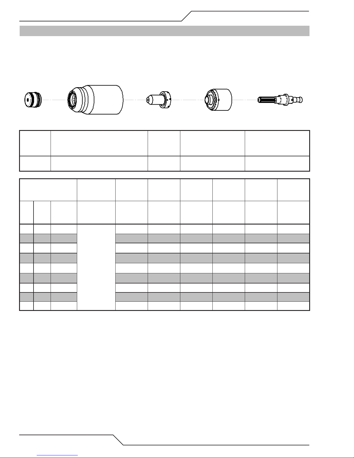
A40i, A60i
4T.09 Recommended Cutting Speeds for Machine and Automated Torches With Shielded Tip
Mild Steel
40A
Air Plasma / Air Shield
Starter Cartridge
Shield Cap Maximum Life Shield Cup Tip
Heavy Duty Starter
Cartridge
Electrode
9-8245 9-8237 9-8208
Material
Thickness
(GA)
(in) inch
20
16
14
12
10
3/16 0.188 115 0.16 65 0.16 0.4 0.07
1/4 0.250 118 0.16 45 0.16 0.5 0.07
3/8 0.375 123 0.16 23 0.16 1.2 0.08
1/2 0.500 128 0.16 18 0.16 2.0 0.08
0.036
0.060 113 0.16 120 0.16 0.0 0.06
0.075 108 0.16 90 0.16 0.1 0.06
0.105 111 0.16 75 0.16 0.2 0.06
0.135 114 0.16 65 0.16 0.3 0.07
Gas Pressure
(Air)
PSI
(torch lead
length)
75 (25')
80 (50')
Arc V oltage
Volts
107 0.16 130 0.16 0.0 0.06
Torch
Working
Height
(in)
Travel Speed
9-8213
9-8277
Initial
Piercing
Height
(ipm) (in) (sec) (in)
Pierce Delay
9-8232
Kerf Width
@ Rec.
Speed
4T-22
OPERATION Manual 0-5466
Page 67

A40i, A60i
Material
Thickness
(mm)
1
2
3
4
5
6
8
10
12
Gas Pressure
(Air)
Bar
(torch lead
length)
5.2 (7.6)
5.5 (15.2)
BOLD TYPE indicates maximum piercing parameters.
Torch
Arc Voltage
Volts (mm) (mm/min) (mm) (sec) (mm)
108
108 4.1 2239 4.1 0.0 1.5
112 4.1 1794 4.1 0.1 1.7
114 4.1 1651 4.1 0.2 1.7
115 4.1 1578 4.1 0.3 1.7
117 4.1 1256 4.1 0.4 1.7
121 4.1 853 4.1 0.5 1.7
124 4.1 565 4.1 1.2 1.8
127 4.1 485 4.1 2.0 1.9
Working
Height
4.1
Travel Speed
3266
Initial
Piercing
Height
4.1
Pierce Delay
0.0 1.4
Kerf Width
@ Rec.
Speed
Manual 0-5466 OPERATION
4T-23
Page 68
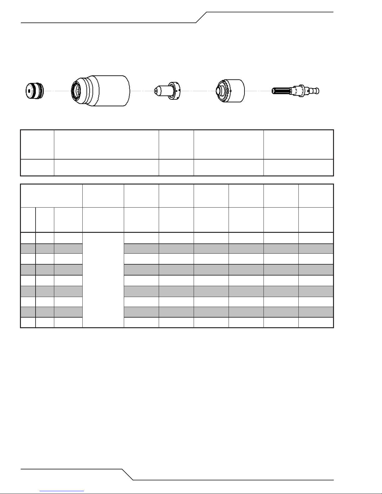
A40i, A60i
Stainless Steel
40A
Air Plasma / Air Shield
Shield Cap Maximum Life Shield Cup Tip
Starter Cartridge
Heavy Duty Starter
Cartridge
Electrode
9-8245 9-8237 9-8208
Material
Thickness
(GA)
(in) inch
18
16
14
12
10
3/16 0.188 115 0.16 30 0.16 0.4 0.07
1/4 0.250 118 0.16 20 0.16 1.2 0.07
3/8 0.375 125 0.16 15 0.16 1.8 0.08
1/2 0.500 127 0.16 10
0.050
0.063 108 0.16 50 0.16 0.1 0.07
0.078 114 0.16 45 0.16 0.1 0.07
0.109 113 0.16 40 0.16 0.2 0.07
0.141 116 0.16 35 0.16 0.3 0.07
Gas Pressure
(Air)
PSI
(torch lead
length)
75 (25')
80 (50')
Arc V oltage
Volts
110 0.16 60 0.16 0.0 0.06
Torch
Working
Height
(in)
Travel Speed
9-8213
9-8277
Initial
Piercing
Height
(ipm) (in) (sec) (in)
0.16
Pierce Delay
2.0 0.08
9-8232
Kerf Width
@ Rec.
Speed
4T-24
OPERATION Manual 0-5466
Page 69

A40i, A60i
Material
Thickness
(mm)
1
2
3
4
5
6
8
10
12
Gas Pressure
(Air)
Bar
(torch lead
length)
5.2 (7.6)
5.5 (15.2)
BOLD TYPE indicates maximum piercing parameters.
Torch
Arc Voltage
Volts (mm) (mm/min) (mm) (sec) (mm)
109
114 4.1 1140 4.1 0.1 1.8
114 4.1 980 4.1 0.2 1.8
116 4.1 845 4.1 0.3 1.8
115 4.1 725 4.1 0.4 1.8
117 4.1 565 4.1 0.5 2.0
122 4.1 440 4.1 1.5 2.0
125 4.1 360 4.1 1.8 2.0
127 4.1 280 4.1 2.0 2.2
Working
Height
4.1
Travel Speed
1670 4.1 0.0 1.7
Initial
Piercing
Height
Pierce Delay
Kerf Width
@ Rec.
Speed
Manual 0-5466 OPERATION
4T-25
Page 70

A40i, A60i
Aluminum
40A
Air Plasma / Air Shield
Shield Cap Maximum Life Shield Cup Tip
Starter Cartridge
Heavy Duty Starter
Cartridge
Electrode
9-8245 9-8237 9-8208
Material
Thickness
(GA)
(in) inch
20
16
12
11
9
3/16 0.188 128 0.19 70 0.20 0.5 0.07
1/4 0.250 137 0.19 30 0.20 1.0 0.08
3/8 0.375 145 0.19 10 0.20 2.0 0.09
0.040
0.063 113 0.19 170 0.20 0.1 0.07
0.097 120 0.19 100 0.20 0.2 0.07
0.125 125 0.19 90 0.20 0.3 0.07
0.160 126 0.19 85 0.20 0.4 0.07
Gas Pressure
(Air)
PSI
(torch lead
length)
75 (25')
80 (50')
Arc V oltage
Volts
110 0.19 300 0.20 0.0 0.06
Torch
Working
Height
(in)
Travel Speed
9-8213
9-8277
Initial
Piercing
Height
(ipm) (in) (sec) (in)
Pierce Delay
9-8232
Kerf Width
@ Rec.
Speed
4T-26
OPERATION Manual 0-5466
Page 71
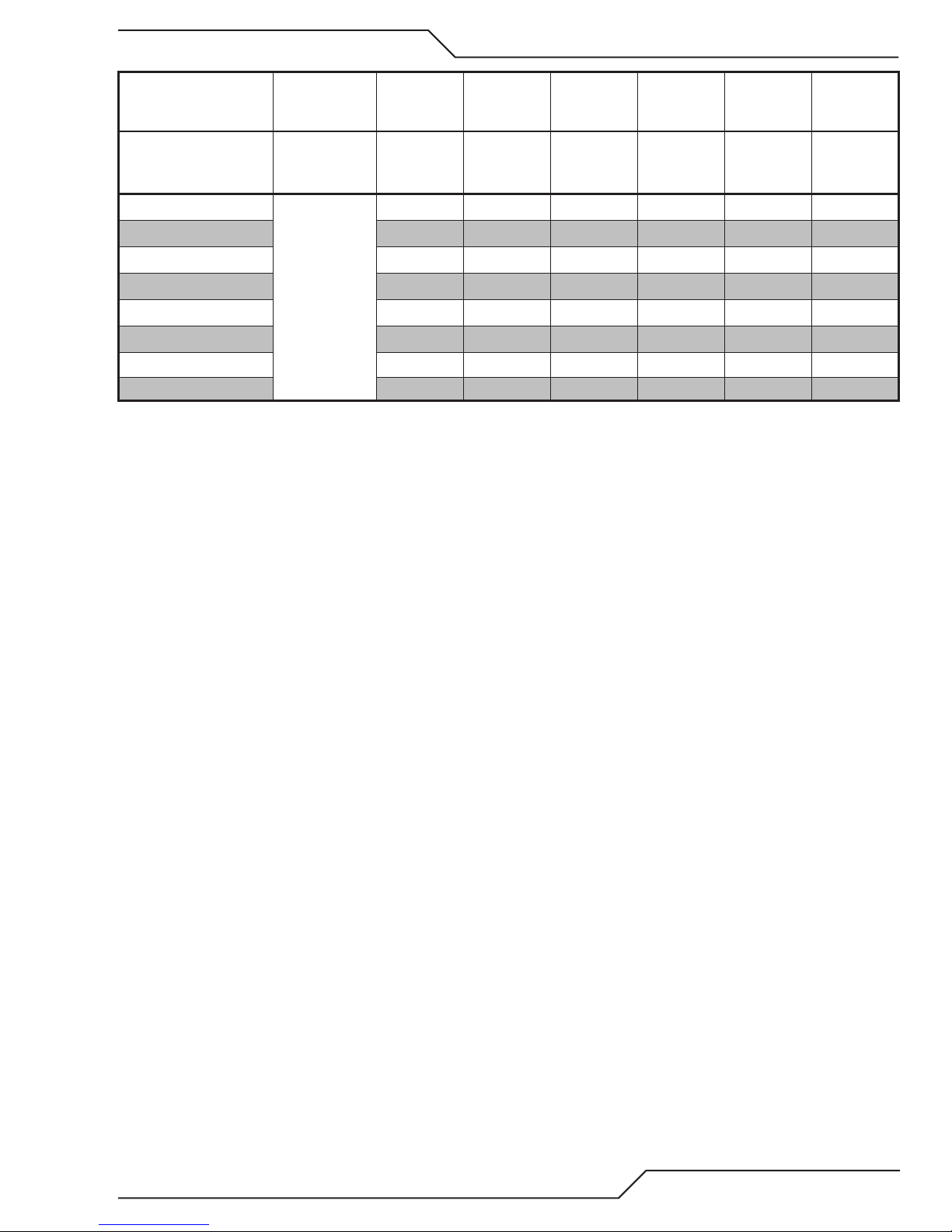
A40i, A60i
Material
Thickness
(mm)
1.0
2.0 116 4.8 3490 5.1 0.2
3.0 124 4.8 2350 5.1 0.3
4.0 126 4.8 2170 5.1 0.4
5.0 129 4.8 1630 5.1 0.6
6.0 135 4.8 990
8.0 141 4.8 500 5.1 1.6 2.0
Gas Pressure
(Air)
Bar
(torch lead
length)
5.2 (7.6)
5.5 (15.2)
Arc Voltage
Volts (mm) (mm/min) (mm) (sec) (mm)
110 4.8 7660 5.1 0.0
Torch
Working
Height
Travel Speed
Initial
Piercing
Height
5.1 1.0
Pierce Delay
10.0 146 4.8 180 5.1 2.1 2.3
BOLD TYPE indicates maximum piercing parameters.
Kerf Width
@ Rec.
Speed
1.6
1.8
1.8
1.8
1.8
1.9
Manual 0-5466 OPERATION
4T-27
Page 72

A40i, A60i
Mild Steel
60A
Air Plasma / Air Shield
Shield Cap Maximum Life Shield Cup Tip
Starter Cartridge
Heavy Duty Starter
Cartridge
Electrode
9-8238 9-8237 9-8210
Material
Thickness
(GA)
(in) inch
16
14
11
10
3/16 0.188 132 0.19 115 0.20 0.20 0.09
1/4 0.250 134 0.19 80 0.20 0.30 0.08
3/8 0.375 132 0.19 34 0.20 0.70 0.10
1/2 0.500 144 0.19 23 0.20 0.75 0.10
5/8 0.625 150 0.19 14 Edge Start 0.10
3/4 0.750 145 0.19 14 Edge Start 0.10
0.060
0.075 129 0.19 237 0.20 0.10 0.09
0.120 126 0.19 200 0.20 0.10 0.08
0.135 128 0.19 142 0.20 0.10 0.09
1 1.000
Gas Pressure
(Air)
PSI
(torch lead
length)
85 (25')
90 (50')
Arc V oltage
Volts
128 0.19 250 0.20 0.00 0.09
160 0.19 4 Edge Start 0.12
Torch
Working
Height
(in)
Travel Speed
9-8213
9-8277
Initial
Piercing
Height
(ipm) (in) (sec) (in)
Pierce Delay
9-8232
Kerf Width
@ Rec.
Speed
4T-28
OPERATION Manual 0-5466
Page 73

A40i, A60i
Material
Thickness
(mm)
1
2
3
4
5
6
8
10
12
15 148 4.8 419 Edge Start 2.6
20 147 4.8 318 Edge Start 2.7
25 159 4.8 118 Edge Start 3.0
BOLD TYPE indicates maximum piercing parameters. BOLD ITALIC indicates edge starts only.
Gas Pressure
(Air)
Bar
(torch lead
length)
5.9 (7.6m)
6.2 (15.2m)
Arc Voltage
Volts (mm) (mm/min) (mm) (sec) (mm)
127
129 4.8 5942 5.1 0.10 2.2
126 4.8 5080 5.1 0.10 0.1
130 4.8 3316 5.1 0.20 2.3
132 4.8 2794 5.1 0.20 2.2
134 4.8 2230 5.1 0.30 2.1
133 4.8 1425 5.1 0.40 2.3
134 4.8 822 5.1 0.60 2.5
141 4.8 646 5.1 0.75 2.5
Torch
Working
Height
4.8
Travel Speed
6804 5.1 0 2.2
Initial
Piercing
Height
Pierce Delay
Kerf Width
@ Rec.
Speed
Manual 0-5466 OPERATION
4T-29
Page 74
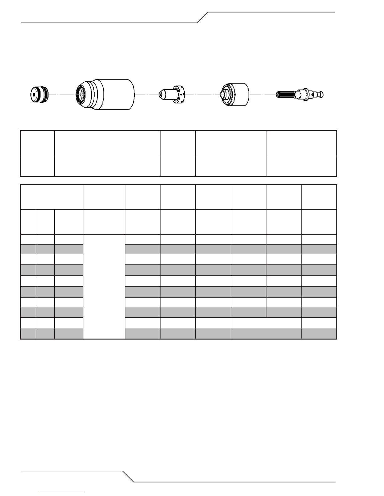
A40i, A60i
Stainless Steel
60A
Air Plasma / Air Shield
Shield Cap Maximum Life Shield Cup Tip
Starter Cartridge
Heavy Duty Starter
Cartridge
Electrode
9-8238 9-8237 9-8210
Material
Thickness
(GA)
(in) inch
16
14
11
10
3/16 0.188 125 0.13 75 0.20 0.20 0.09
1/4 0.250 127 0.13 60 0.20 0.30 0.08
3/8 0.375 134 0.13 28 0.20 0.50 0.08
1/2 0.500 136 0.19 17 0.25 0.75 0.09
5/8 0.625 131 0.13 14 Edge Start 0.08
3/4 0.750 142 0.19 10 Edge Start 0.11
0.063
0.078 116 0.13 155 0.20 0.10 0.07
0.125 118 0.13 125 0.20 0.10 0.07
0.141 126 0.13 80 0.20 0.10 0.09
Gas Pressure
(Air)
PSI
(torch lead
length)
85 (25')
90 (50')
Arc V oltage
Volts
110 0.13 165 0.20 0.00 0.06
Torch
Working
Height
(in)
Travel Speed
9-8213
9-8277
Initial
Piercing
Height
(ipm) (in) (sec) (in)
Pierce Delay
9-8232
Kerf Width
@ Rec.
Speed
4T-30
OPERATION Manual 0-5466
Page 75

A40i, A60i
Material
Thickness
(mm)
1
2
3
4
5
6
8
10
12
15 132 3.3 375 Edge Start 2.6
20
BOLD TYPE indicates maximum piercing parameters. BOLD ITALIC indicates edge starts only.
Gas Pressure
(Air)
Bar
(torch lead
length)
5.9 (7.6m)
6.2 (15.2m)
Arc Voltage
Volts (mm) (mm/min) (mm) (sec) (mm)
101
116 3.3 3925 5.1 0.10 1.7
118 3.3 3285 5.1 0.10 1.7
126 3.3 1985 5.1 0.20 2.2
125 3.3 1850 5.1 0.20 2.1
127 3.3 1605 5.1 0.30 2.1
131 3.3 1100 5.1 0.40 2.1
134 3.3 670 5.1 0.50 2.1
136 4.8 490 6.4 0.90 2.2
144 4.8 230 Edge Start 2.5
Torch
Working
Height
3.3
Travel Speed
4590 5.1 0.00 1.2
Initial
Piercing
Height
Pierce Delay
Kerf Width
@ Rec.
Speed
Manual 0-5466 OPERATION
4T-31
Page 76
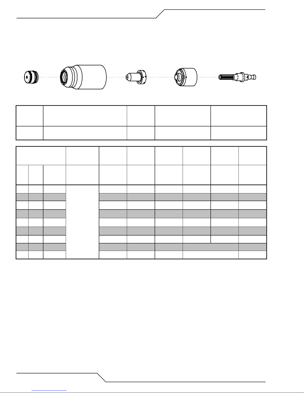
A40i, A60i
Aluminum
60A
Air Plasma / Air Shield
Shield Cap Maximum Life Shield Cup Tip
Starter Cartridge
Heavy Duty Starter
Cartridge
Electrode
9-8238 9-8237 9-8210
Material
Thickness
(GA)
(in) inch
16
14
11
3/16 0.188 125 0.13 140 0.25 0.20 0.08
1/4 0.250 132 0.13 80 0.25 0.30 0.08
3/8 0.375 135 0.13 45 0.25 0.50 0.08
1/2 0.500 140 0.13 26 0.25 0.80 0.08
5/8 0.625 148 0.19 18 Edge start 0.10
3/4 0.750 155 0.19 12 Edge start 0.11
0.064
0.079 118 0.13 350 0.25 0.10 0.08
0.120 123 0.13 275 0.25 0.10 0.08
Gas Pressure
(Air)
PSI
(torch lead
length)
85 (25')
90 (50')
Arc V oltage
Volts
118 0.13 350 0.25 0.00 0.07
Torch
Working
Height
(in)
Travel Speed
9-8213
9-8277
Initial
Piercing
Height
(ipm) (in) (sec) (in)
Pierce Delay
9-8232
Kerf Width
@ Rec.
Speed
4T-32
OPERATION Manual 0-5466
Page 77

A40i, A60i
Material
Thickness
(mm)
1
2 118 6.4 8890 6.4 0.10
3 123 6.4 7070 6.4 0.10
4 124 6.4 5095 6.4 0.20
5 126 6.4 3335 6.4 0.20
6 130 6.4 2370
8 134 6.4 1570 6.4 0.40 2.0
Gas Pressure
(Air)
Bar
(torch lead
length)
5.9 (7.6m)
6.2 (15.2m)
Arc Voltage
Volts (mm) (mm/min) (mm) (sec) (mm)
118 6.4 8890 6.4 0.00
Torch
Working
Height
Travel Speed
Initial
Piercing
Height
6.4 0.30
Pierce Delay
10 136 6.4 1070 6.4 0.60 2.0
12 139 6.4 765 6.4 0.70 2.0
15 146 4.8 515 Edge start 2.4
20 157 4.8 260 Edge start 2.7
BOLD TYPE indicates maximum piercing parameters. BOLD ITALIC indicates edge starts only.
Kerf Width
@ Rec.
Speed
2
2.0
2.1
2.0
2.0
2.0
Manual 0-5466 OPERATION
4T-33
Page 78

A40i, A60i
PATENT INFORMATION
Plasma Cuing Torch Patents
The following parts are covered under U.S. and Foreign Patents as follows:
Catalog # Description Patent(s)
9-8215 Electrode US Pat No(s) 6163008; 6987238
Other Pat(s) Pending
9-8232 Electrode US Pat No(s) 6163008; 6987238
Other Pat(s) Pending
9-8213 Cartridge US Pat No(s) 6903301; 6717096; 6936786;
6703581; D496842; D511280; D492709; D499620;
D504142 Other Pat(s) Pending
9-8205 Tip US Pat No(s) 6774336; 7145099; 6933461
Other Pat(s) Pending
9-8206 Tip US Pat No(s) 6774336; 7145099; 6933461
Other Pat(s) Pending
9-8207 Tip US Pat No(s) 6774336; 7145099; 6933461
Other Pat(s) Pending
9-8252 Tip US Pat No(s) 6774336; 7145099; 6933461
Other Pat(s) Pending
9-8208 Tip US Pat No(s) 6774336; 7145099; 6933461
Other Pat(s) Pending
9-8209 Tip US Pat No(s) 6774336; 7145099; 6933461
Other Pat(s) Pending
9-8210 Tip US Pat No(s) 6774336; 7145099; 6933461
Other Pat(s) Pending
9-8231 Tip US Pat No(s) 6774336; 7145099; 6933461
Other Pat(s) Pending
9-8211 Tip US Pat No(s) 6774336; 7145099; 6933461
Other Pat(s) Pending
9-8212 Tip US Pat No(s) 6774336; 7145099; 6933461
Other Pat(s) Pending
9-8253 Tip US Pat No(s) 6774336; 7145099; 6933461
Other Pat(s) Pending
9-8233 Tip US Pat No(s) 6774336; 7145099; 6933461
Other Pat(s) Pending
9-8225 Tip US Pat No(s) 6774336; 7145099; 6933461
Other Pat(s) Pending
9-8226 Tip US Pat No(s) 6774336; 7145099; 6933461
Other Pat(s) Pending
9-8227 Tip US Pat No(s) 6774336; 7145099; 6933461
Other Pat(s) Pending
9-8228 Tip US Pat No(s) 6774336; 7145099; 6933461
Other Pat(s) Pending
9-8241 Shield Cap US Pat No(s) 6914211; D505309
Other Pat(s) Pending
9-8243 Shield Cap US Pat No(s) 6914211; D493183
Other Pat(s) Pending
9-8235 Shield Cap US Pat No(s) 6914211; D505309
Other Pat(s) Pending
9-8236 Shield Cap US Pat No(s) 6914211; D505309
Other Pat(s) Pending
9-8237 Shield Cup US Pat No(s) 6914211; D501632; D511633
Other Pat(s) Pending
9-8238 Shield Cap US Pat No(s) 6914211; D496951
Other Pat(s) Pending
4T-34
OPERATION Manual 0-5466
Page 79

Catalog # Description Patent(s)
9-8239 Shield Cap US Pat No(s) 6914211; D496951
Other Pat(s) Pending
9-8244 Shield Cap US Pat No(s) 6914211; D505309
Other Pat(s) Pending
9-8245 Shield Cap US Pat No(s) 6914211; D496951
Other Pat(s) Pending
The following parts are also licensed under U.S. Patent No. 5,120,930 and 5,132,512:
Catalog # Description
9-8235 Shield Cap
9-8236 Shield Cap
9-8237 Shield Cup
9-8238 Shield Cap
9-8239 Shield Cap
9-8244 Shield Cap
9-8245 Shield Cap
A40i, A60i
Manual 0-5466 OPERATION
4T-35
Page 80

A40i, A60i
This Page Intentionally Blank
4T-36
OPERATION Manual 0-5466
Page 81

5.01 General Maintenance
A40i, A60i
SECTION 5 SYSTEM:
SERVICE
Warning!
Disconnect input power before maintaining.
Visually inspect the torch body,
consumables and Quick Connect
Maintain more often
if used under severe
conditions
Each Use
Visual check of
torch tip and electrode
Weekly
Visually inspect the
cables and leads.
Replace as needed
Art# A-13267
Replace all
broken parts
3 Months
Clean
exterior
of power supply
Manual 0-5466 SERVICE
5-1
Page 82

A40i, A60i
5.02 Maintenance Schedule
NOTE!
The actual frequency of maintenance may
need to be adjusted according to the operating environment.
Daily Operational Checks or Every Six Cutting Hours:
1. Check torch consumable parts, replace if damaged or worn.
2. Check plasma and secondary supply and pressure/flow.
3. Purge plasma gas line to remove any moisture build-up.
Weekly or Every 30 Cutting Hours:
1. Check fan for proper operation and adequate air flow.
2. Inspect torch for any cracks or exposed wires, replace if necessary.
3. Inspect input power cable for damage or exposed wires, replace if necessary.
Six Months or Every 720 Cutting Hours:
1. Check the in-line air filter(s), clean or replace as required.
2. Check cables and hoses for leaks or cracks, replace if necessary.
CAUTION
!
Do not blow air into the power supply during
cleaning. Blowing air into the unit can cause
metal particles to interfere with sensitive
electrical components and cause damage to
the unit.
SERVICE Manual 0-5466
5-2
Page 83

5.03 Common Faults
Problem - Symptom Common Cause
Insufficient
Penetration
A40i, A60i
1. Cutting speed too fast.
2. Torch tilted too much.
3. Metal too thick.
4. Worn torch parts
5. Cutting current too low.
6. Non - Genuine Thermal Dynamics parts used
7. Incorrect gas pressure
Main Arc
Extinguishes
Excessive Dross
Formation
Short Torch Parts Life1. Oil or moisture in air source.
1. Cutting speed too slow.
2. Torch standoff too high from workpiece.
3. Cutting current too high.
4. Work cable disconnected.
5. Worn torch parts.
6. Non - Genuine Thermal Dynamics parts used
1. Cutting speed too slow.
2. Torch standoff too high from workpiece.
3. Worn torch parts.
4. Improper cutting current.
5. Non - Genuine Thermal Dynamics parts used
6. Incorrect gas pressure
2. Exceeding system capability (material too thick).
3. Excessive pilot arc time
4. Gas pressure too low.
5. Improperly assembled torch.
6. Non - Genuine Thermal Dynamics parts used
Difficult Starting 1. Worn torch parts.
Manual 0-5466 SERVICE
2. Non - Genuine Thermal Dynamics parts used.
3. Incorrect gas pressure.
5-3
Page 84

A40i, A60i
5.04 Fault Indicator
At initial power up, the system goes through a series of self checks before it is ready for use. If during those checks
it detects something is not within proper operating parameters, a fault will occur. If that happens the Fault indicator
will light followed by the Error Code , and number in the digital display.
Error Code Indicator
Indicates when there is something that needs to be adjusted or repaired.
E001, E002, etc. Light up fault indicator also.
Error Code Description
E001 Over Temp Ambient too high, duty cycle exceeded, fan failure or other internal fault.
E002 Input Fault Input voltage outside the range of the unit or internal fault resulting in low bus
voltage.
1phase / 3phase jumpers J300 on Bias PCB set wrong.
E004 PIP Fault Parts in Place fault. Shield cup not in place or tight.
E005 PIC Fault Parts in Contact fault. Missing or worn tip/start cartridge or electrode.
Inlet pressure exceeds rating causing continuous gas flow.
E009 Fan Fault Fan failed or disconnected.
E012 Output Fault Tip to electrode voltage too low. Consumables fail to separate when gas flows,
start cartridge stuck, failed power supply, no output or shorted torch body.
E014 Trigger Fault Torch trigger (start signal) active at start up.
E016 Pressure Fault Low pressure. Output pressure too low for selected parameters.
SERVICE Manual 0-5466
5-4
Page 85

5.05 Basic Troubleshooting Guide
WARNING
There are extremely dangerous voltage and power levels present inside this unit. Do not
attempt to diagnose or repair unless you have had training in power electronics measurement and troubleshooting techniques.
Problem - Symptom Possible Cause Recommended Action
ON / OFF Switch
is ON but the A/C
Indicator does not
light
1. Primary power disconnect is in
OFF position.
2. Primary fuses / breakers are
blown or tripped.
3. Faulty components in unit.
1. Turn primary power disconnect switch to ON position.
2. a) Have qualified person check primary fuses / breakers.
b) Connect unit to known good primary power receptacle
3. Return to authorized service center for repair or replacement.
A40i, A60i
Fault indicator
flashing, Error Code
E002
TEMPERATURE
indicator ON.
FAULT indicator
flashing. Error Code
E001
GAS LED OFF,
FAULT and MIN
pressure indicators
flashing. Error Code
E016
FAULT and indicators
flashing. Error Code
E004
FAULT and indicators
flashing. Error Code
E014
1. Primary input voltage problem.
2. Faulty components in unit.
1. Air flow through or around the
unit is obstructed.
2. Duty cycle of the unit has been
exceeded.
3. Failed components in unit.
1. Gas supply not connected to
unit.
2. Gas supply not turned ON.
3. Gas supply pressure too low.
4. Failed components in unit.
1. Shield Cup loose.
2. Torch not properly connected to
power supply.
3. Problem in torch and leads PIP
circuit.
4. Failed components in unit.
1. Start signal is active when ON/
OFF SWITCH is turned to ON
position.
2. Problem in the torch and leads
switch circuit.
3. Failed components in unit.
1. Have qualified person check primary voltage to insure it
meets unit requirements see Section
Specifications" on page 2-3.
2. Return to authorized service center for repair or replacement.
1. Refer to clearance information – see Section "2.04 Power
Supply Specifications" on page 2-2
2. Allow unit to cool.
3. Return to authorized service center for repair or replacement.
1. Connect gas supply to unit.
2. Turn gas supply ON.
3. Set air supply inlet pressure to unit to 120 psi.
4. Return to authorized service center for repair or replacement.
1. Hand tighten the shield cup until it is snug.
2. Insure torch ATC is securely fastened to unit.
3. Replace torch and leads or return to authorized service center
for repair or replacement.
4. Return to authorized service center for repair or replacement.
1. Start can be active for one of the following:
• Hand torch switch held closed
• Hand pendant switch held closed
• CNC START signal is active low
Release the START signal source
2. Replace torch and leads or return to authorized service center
for repair or replacement.
3. Return to authorized service center for repair or replacement.
"2.05 Input Wiring
Manual 0-5466 SERVICE
5-5
Page 86

A40i, A60i
Problem - Symptom Possible Cause Recommended Action
FAULT indicators
flashing. Gas flow is
cycling ON and OFF.
Error code E005
1. Torch shield cup is loose.
2. Torch tip, electrode or starter
cartridge missing.
3. Torch start cartridge is stuck.
4. Unit inlet gas pressure is too
high causing continuous gas flow.
5. Open conductor in torch leads.
6. Problem in the torch and leads
switch circuit.
7. Failed components in unit.
1. Tighten shield cup by hand. Do not overtighten.
2. Turn OFF power supply. Remove shield cup. Install missing
parts.
3. Turn OFF power supply. Bleed down system pressure.
Remove shield cup, tip and start cartridge. Check start cartridge
lower end fitting for free movement. Replace if fitting does not
move freely.
4. Decrease gas supply pressure to 125 PSI or less.
5. Replace torch and leads or return to authorized service center
for repair or replacement.
6. Replace torch and leads or return to authorized service center
for repair or replacement.
7. Return to authorized service center for repair or replacement.
Nothing happens
when torch switch
or remote switch
is closed (Or CNC
START signal is
active) No gas flow,
DC LED OFF.
FAULT indicators
flashing. Error code
E012
No Fault lights ON, no
arc in torch.
FAULT indicators
flashing Error code
E024 or E031
Pilot arc is ON but
cutting arc will not
establish
1. Problem in the torch and leads
switch circuit (Remote pendant
switch circuit).
2. CNC Controller device not
providing Start signal.
3. Failed components in unit.
1. Upper O-ring on torch head is in
wrong position.
2. Torch starter cartridge is stuck.
3. Worn or faulty torch parts.
4. Shorted Torch.
1. Failed components in unit. 1. Return to an authorized service center for repair.
1. Internal Error 1. Turn the ON / OFF switch OFF then back ON again. If that does
1. Work cable not connected to
work piece.
2. Work cable/connector broken.
3. Failed components in unit.
1. Take Torch and Leads (Remote Pendant) to Authorized Repair
Facility.
2. Contact Controller manufacturer.
3. Return to authorized service center for repair or replacement.
1. Remove shield cup from torch; check upper O-ring position;
correct if necessary.
2. Turn OFF power supply. Bleed down system pressure.
Remove shield cup, tip and starter cartridge. Check starter
cartridge lower end fitting for free movement. Replace if fitting
does not move freely.
3. Inspect torch consumable parts. Replace if necessary.
4. Replace torch and leads or return to an authorized service
center for repair.
not clear the fault, return to an authorized service center for
repair.
1. Connect work cable.
2. Replace work cable.
3. Return to an authorized service center for repair.
Torch cutting is
diminished
SERVICE Manual 0-5466
5-6
1. Incorrect current setting.
2. Worn torch consumables.
3. Poor work cable connection to
work piece.
4. Torch being moved too fast.
5. Excessive oil or water in torch.
6. Failed components in unit.
1. Check and adjust to proper setting.
2. Check torch consumables and replace as needed.
3. Check the connection of the Work Lead to the work piece.
4. Reduce cutting speed.
5. Refer to "Check air quality" in Section 3 Torch.
6. Return to an authorized service center for repair.
Page 87

A40i, A60i
5.06 Power Supply Basic Parts Replacement
WARNING
Disconnect primary power to the system
before disassembling the torch, leads, or
power supply.
This section describes procedures for basic parts replacement. For more detailed parts replacement procedures,
refer to the Power Supply Service Manual.
A. Filter Element Assembly Replacement
The Filter Element Assembly is in the rear panel. For better system performance, the filter element should be checked
per the Maintenance Schedule (Section 5.02), and either cleaned or replaced.
Regulator/Filter
Assembly
Art # A-13255
1. Remove power from the power supply; turn OFF the gas supply and bleed down the system.
2. Remove the clear filter bowl with wrench provided with the system.
NOTE!
Filter replacement part numbers can be
found in Section 6 of this manual
Manual 0-5466 SERVICE
5-7
Page 88

A40i, A60i
Art # A-07990
3. Remove the filter element and clean or replace..
NOTE!
If replacing or cleaning just the filter element refer to the following illustration for
disassembly.
Filter Element
4. Install the new or cleaned assembly by reversing these procedures.
5. Turn ON the air supply and check for leaks before reinstalling the cover.
Optional Single-Stage Filter Element Replacement
These instructions apply to power supplies where the optional Single-Stage Filter has been installed.
The Power Supply shuts down automatically when the Filter Element becomes completely saturated. The Filter
Element can be removed from its housing, dried, and reused. Allow 24 hours for Element to dry. Refer to Section
6, Parts List, for replacement filter element catalog number.
1. Remove power from power supply.
2. Shut OFF air supply and bleed down system before disassembling Filter to change Filter Element.
3. Disconnect gas supply hose.
SERVICE Manual 0-5466
5-8
Page 89
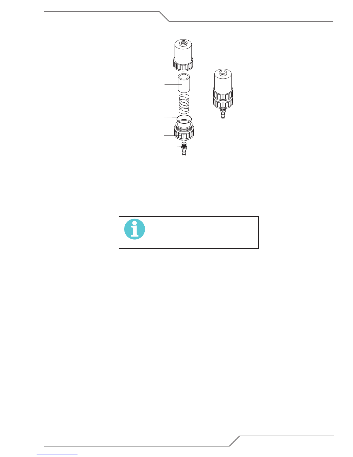
A40i, A60i
led Filter
(Cat.
4. Turn the Filter Housing Cover counter-clockwise and remove it. The Filter Element is located inside the
Housing.
Housing
Filter
Element
(Cat. No. 9-7741)
Spring
O-ring
No. 9-7743)
Cover
Barbed
Fitting
Optional Single-Stage Filter Element Replacement
5. Remove the Filter Element from the Housing and set Element aside to dry.
Assemb
Art # A-02476
6. Wipe inside of housing clean, then insert the replacement Filter Element open side first.
7. Replace Housing on Cover.
8. Reattach gas supply.
NOTE!
If unit leaks between housing and cover,
inspect the O-ring for cuts or other damage.
Manual 0-5466 SERVICE
5-9
Page 90

A40i, A60i
!
First & Second
Optional Two-Stage Filter Element Replacement
The Two-Stage Air Filter has two Filter Elements. When the Filter Elements become dirty the Power Supply will
continue to operate but cut quality may become unacceptable. Refer to Section 6, Parts List, for replacement filter
element catalog number.
1. Shut OFF primary input power.
2. Shut OFF air supply and bleed down system.
WARNING
Always turn OFF the air supply and bleed
the system before disassembling the Filter
Assembly as injury could result.
3. Loosen the two bolts on the top of the Filter Assembly enough to allow the Filter Elements to move freely.
4. Note the location and orientation of the old Filter Elements.
5. Slide out the old Filter Elements.
Stage
Cartridges
(as marked)
Art # A-02942
Optional Two-Stage Filter Replacement
6. Slide the replacement Filter Elements into the Filter Assembly, with the same orientation as noted in Step 4
above.
7. Hand tighten the two bolts evenly, then torque each bolt to 20 - 30 in-lbs (2.3 - 3.4 Nm). Improper torque
may damage the gasket.
8. Slowly apply air pressure to the assembly, checking for leaks.
NOTE!
A small amount of air leakage from the bottom fitting is normal.
NOTE!
Filter replacement part numbers can be
found in Section 6 of this manual
This completes the parts replacement procedures.
SERVICE Manual 0-5466
5-10
Page 91
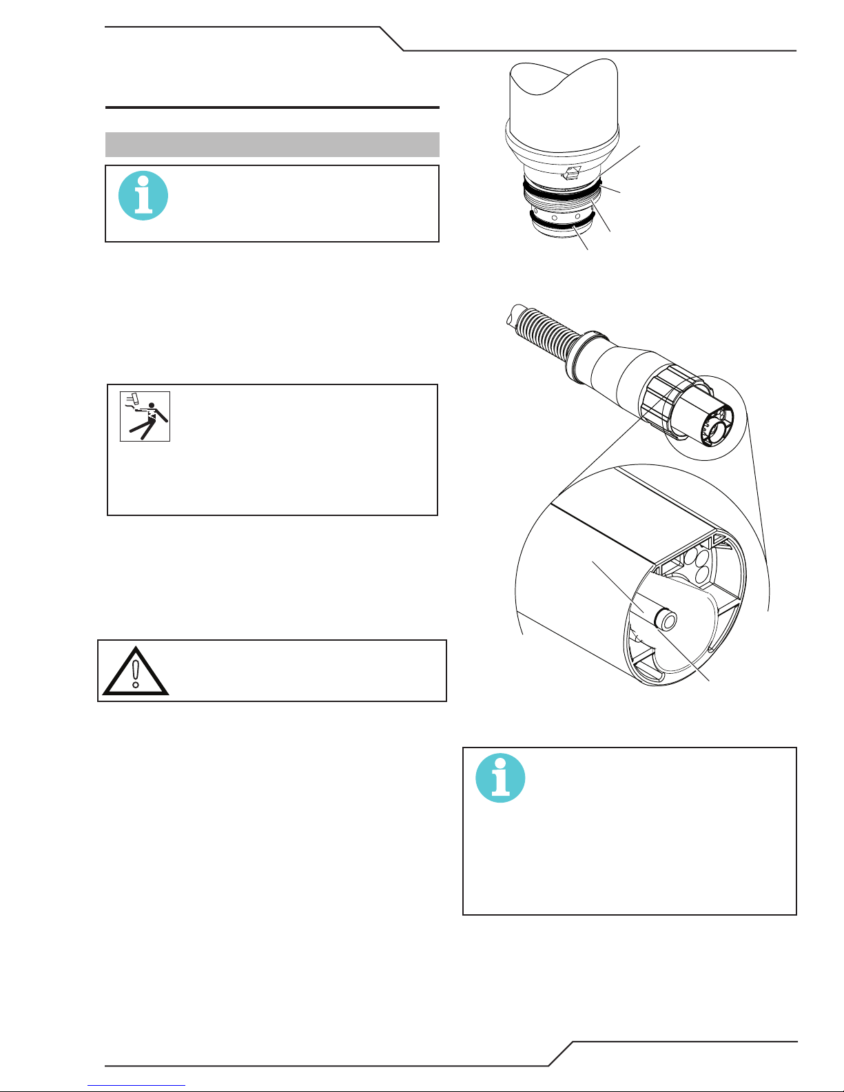
SECTION 5 TORCH:
!
Must Remain Open
Lower O-Ring
Art # A-03725
Art #A-03791_AB
SERVICE
A40i, A60i
5T.01 General Maintenance
NOTE!
Refer to Previous “Section 5: System” for
common and fault indicator descriptions.
Cleaning Torch
Even if precautions are taken to use only clean air
with a torch, eventually the inside of the torch becomes coated with residue. This buildup can affect
the pilot arc initiation and the overall cut quality of
the torch.
WARNING
Disconnect primary power to the system
before disassembling the torch or torch
leads.
DO NOT touch any internal torch parts
while the AC indicator light of the Power
Supply is ON.
Upper Groove
with Vent Holes
Upper O-Ring
in Correct Groove
Threads
Torch Head O-Ring
ATC Male Connector
The inside of the torch should be cleaned with electrical contact cleaner using a cotton swab or soft wet
rag. In severe cases, the torch can be removed from
the leads and cleaned more thoroughly by pouring
electrical contact cleaner into the torch and blowing
it through with compressed air.
CAUTION
Dry the torch thoroughly before reinstalling.
O-Ring Lubrication
An O-Ring on the Torch Head and ATC Male Connector requires lubrication on a scheduled basis.
This will allow the O-Rings to remain pliable and
provide a proper seal. The O-Rings will dry out,
becoming hard and cracked if the lubricant is not
used on a regular basis. This can lead to potential
performance problems.
It is recommended to apply a very light film of ORing lubricant (Catalog # 8-4025) to the O-Rings on
a weekly basis.
Gas Fitting
O-Ring
ATC O-Ring
NOTE!
DO NOT use other lubricants or grease,
they may not be designed to operate
within high temperatures or may contain
“unknown elements” that may react with
the atmosphere. This reaction can leave
contaminants inside the torch. Either of
these conditions can lead to inconsistent
performance or poor parts life.
Manual 0-5466 SERVICE
5T-1
Page 92
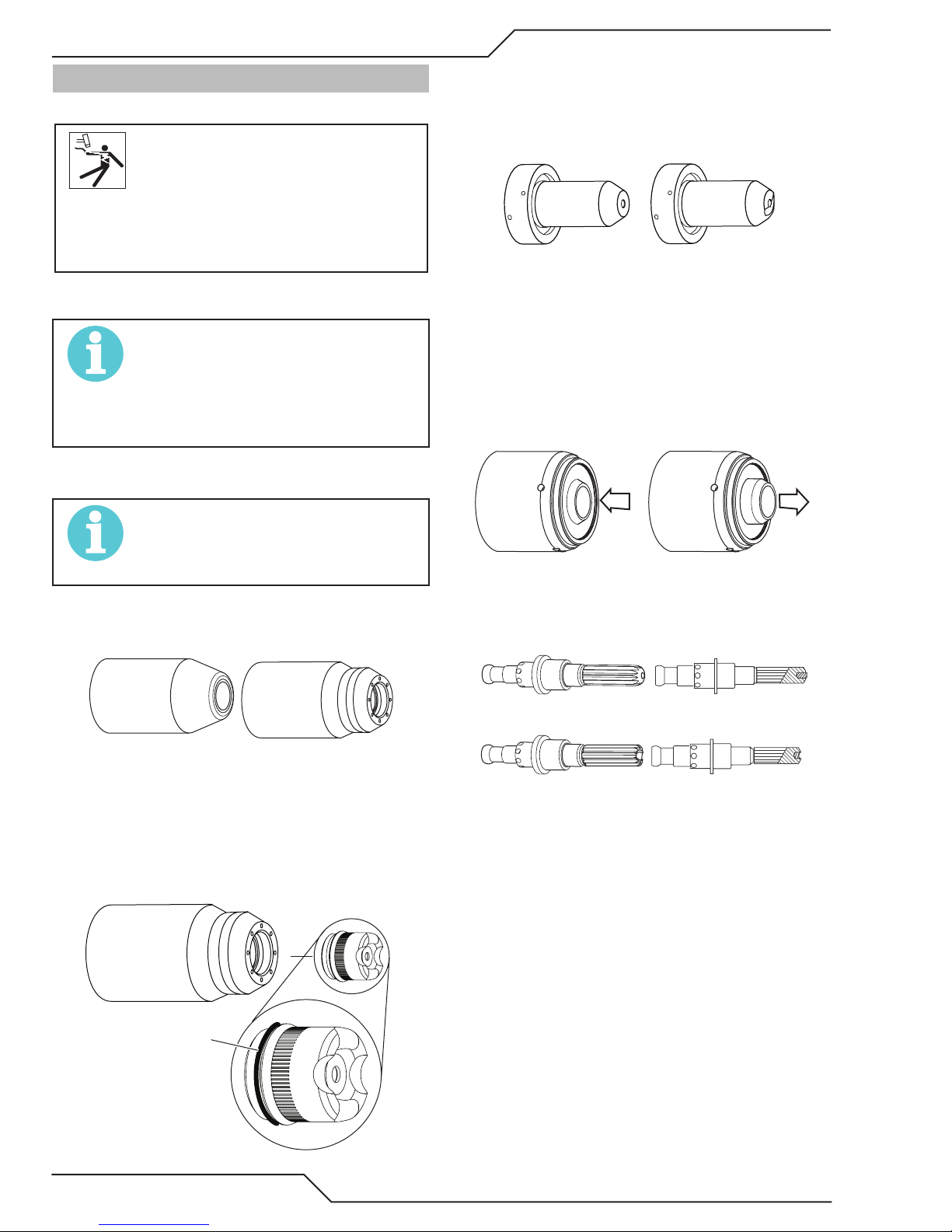
A40i, A60i
Art # A-08067
Drag Shield Cap
Good Tip
Worn Tip
A-03406
Art # A-08064_AC
Spring-Loaded
Spring-Loaded
Art # A-03284
5T.02 Inspection and Replacement of
Consumable Torch Parts
WARNING
Disconnect primary power to the system
before disassembling the torch or torch
leads.
DO NOT touch any internal torch parts
while the AC indicator light of the Power
Supply is ON.
Remove the consumable torch parts as follows:
NOTE!
The shield cup holds the tip and starter
cartridge in place. Position the torch with
the shield cup facing upward to prevent
these parts from falling out when the cup is
removed.
1. Unscrew and remove the shield cup from the
torch.
NOTE!
Slag built up on the shield cup that cannot
be removed may effect the performance of
the system.
2. Inspect the cup for damage. Wipe it clean or
replace if damaged.
4. Remove the tip. Check for excessive wear (indicated by an elongated or oversized orifice). Clean
or replace the tip if necessary.
Example of Tip Wear
5. Remove the starter cartridge. Check for excessive
wear, plugged gas holes, or discoloration. Check
the lower end fitting for free motion. Replace if
necessary.
Lower End Fitting
Full Compression
Lower End Fitting at Reset /
Full Extension
6. Pull the Electrode straight out of the Torch Head.
Check the face of the electrode for excessive wear.
Refer to the following figure.
3. On torches with a shield cup body and a shield
Shield Cups
cap or deflector, ensure that the cap or deflector
is threaded snugly against the shield cup body.
In shielded drag cutting operations (only), there
may be an O-Ring between the shield cup body
and drag shield cap. Do not lubricate the O-Ring.
Shield
Cup Body
O-Ring No. 8-3488
Art # A-03878
New Electrode
Worn Electrode
Electrode Wear
7. Reinstall the Electrode by pushing it straight into
the torch head until it clicks.
8. Reinstall the desired starter cartridge and tip into
the torch head.
9. Hand tighten the shield cup until it is seated on
the torch head. If resistance is felt when installing
the cup, check the threads before proceeding.
This completes the parts replacement procedures.
SERVICE Manual 0-5466
5T-2
Page 93

A40i, A60i
SECTION 6:
PARTS LISTS
6.01 Introduction
A. Parts List Breakdown
The parts list provide a breakdown of all replaceable components. The parts lists are arranged as follows:
6.03 Power Supply Replacement
6.04 Replacement Power Supply Parts
6.05 Options and Accessories
6.06 Replacement Parts for SL100SLV Torch with Solenoid on Tube
6.07 Replacement Parts - for Machine Torches with Unshielded Leads
6.08 Torch Consumable Parts Automation / Machine (SL100)Torch
NOTE
Parts listed without item numbers are not shown, but may be ordered by the catalog number shown.
B. Returns
If a product must be returned for service, contact your distributor. Materials returned without proper authorization
will not be accepted.
6.02 Ordering Information
Order replacement parts by catalog number and complete description of the part or assembly, as listed in the parts
list for each type item. Also include the model and serial number of the power supply. Address all inquiries to
your authorized distributor.
6.03 Power Supply Replacement
The following items are included with the replacement power supply: work cable & clamp, input power cable, gas
pressure regulator / filter, and operating manual.
Qty Description Catalog #
1 A40i Power Supply
208-480V, Single Phase 3-5634-1
1 A40i Power Supply
208-480V Three Phase 3-5634-2
1 A40i Power Supply
400V Three Phase 3-5634-3
1 A40i Power Supply
400V, Three Phase, CE, 3-5634-4
1 A40i Power Supply
400V, Three Phase, CCC, 3-5634-3C
1 A60i Power Supply
400V Three Phase 3-6634-3
1 A60i Power Supply
400V, Three Phase, CE, 3-6634-4
1 A60i Power Supply
400V, Three Phase, CCC, 3-6634-3C
Manual 0-5466 PARTS LIST
6-1
Page 94

A40i, A60i
led Filter
(Cat.
First & Second
6.04 Replacement Power Supply Parts
Qty Description Catalog #
1 Filter Assembly Replacement Element 9-0116
1 Input Power Cord for 208/480 V Power Supply
6.05 Options and Accessories
Qty Description Catalog #
1 Single - Stage Filter Kit (includes Filter & Hose) 7-7507
1 Replacement Filter Body 9-7740
1 Replacement Filter Hose (not shown) 9-7742
2 Replacement Filter Element 9-7741
1 Two - Stage Filter Kit (includes Hose & Mounting Screws) 9-9387
1 Two - Stage Air Filter Assembly 9-7527
1 First Stage Cartridge 9-1021
1 Second Stage Cartridge 9-1022
1 Work Cable #8 with 50mm Dinse plug 9-9692
1 Multi - Purpose Cart 7-8888
1 Filter Wrench (Factory Filter) 9-9675
Housing
Filter
Element
(Cat. No. 9-7741)
Spring
O-ring
No. 9-7743)
Cover
Barbed
Fitting
Optional Single - Stage Filter Kit Optional Two - Stage Filter Kit
Assemb
Art # A-02476
Stage
Cartridges
(as marked)
Art # A-02942
PARTS LIST Manual 0-5466
6-2
Page 95

This Page Intentionally Blank
A40i, A60i
Manual 0-5466 PARTS LIST
6-3
Page 96

A40i, A60i
6.06 Torch Replacement Parts SL100SV Torch (with Solenoid on Mounting Tube)
Item No. Qty Description Catalog No.
1 1 Torch Head Assembly without leads (includes items 2, 3, and 14) 9-8220
2 1 Large O-Ring 8-3487
3 1 Small O-Ring 8-3486
4 1 PIP Switch Kit 9-7036
5 1 PIP Plunger and Return Spring Kit 9-7045
6 Automated Leads Assemblies with ATC connectors
1 25 - foot / 7.6 m Leads Assembly with ATC connector 4-3058
1 35 - foot / 10.6 m Leads Assembly with ATC connector 4-3059
1 50 - foot / 15.2 m Leads Assembly with ATC connector 4-3060
7 1 Rack 9-9448
8 1 Mounting Tube 9-9445
9 1 End Cap Assembly 9-7044
10 2 Body, Mounting, Pinch Block 9-4513
11 1 Pin, Mounting, Pinch Block 9-4521
12 1 Torch Holder Sleeve 7-2896
13 1 Pinion Assembly (does not include positioning tube) 7-2827
14 1 Torch Holder Sleeve 7-2896
15 1 Pinion Gear-Short 8-6074
16 1 Handwheel (Torch Holder) 9-4514
17 1 Low Profile Torch Holder (1 3/8 Dia) w/o Hardware 9-4515
18 1 Calibrated Torch Holder Bushing 9-4366
19 1 5/32 Dia x 5/8 Lg Slotted Spring Pin See Note 1
20 1 3/8-24 x 3/8 Soc Hd Set Screw, Cup Point See Note 1
21 2 1/4-20 x 5/8 Hex Socket Head Screw See Note 1
22 1 #10-24 x 3/8 Hex Socket Set Screw, Cup Point See Note 1
23 1 Solenoid Assembly 9-9447
24 1 Solenoid Cover 9-9446
Purchase these parts locally.
NOTE
PARTS LIST Manual 0-5466
6-4
Page 97
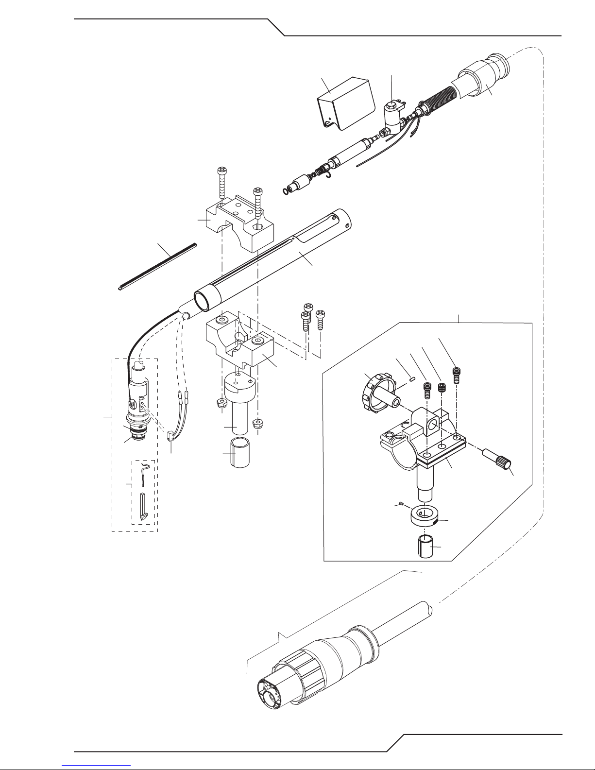
A40i, A60i
1
24
10
7
8
10
16
23
19
21
20
9
13
21
12
11
17
22
18
14
6
Art # A-07113
15
2
3
4
5
Manual 0-5466 PARTS LIST
6-5
Page 98

A40i, A60i
6.07 Replacement Parts - for Machine Torches with Unshielded Leads
Item No. Qty Description Catalog No.
1 1 Torch Head Assembly without leads (includes items 2, 3, and 14) 9-8220
2 1 Large O-Ring 8-3487
3 1 Small O-Ring 8-3486
4 1 PIP Switch Kit 9-7036
5 Unshielded Automated Leads Assemblies with ATC connectors
1 5 - foot / 1.5 m Leads Assembly with ATC connector 4-7850
1 10 - foot / 3.05 m Leads Assembly with ATC connector 4-7851
1 25 - foot / 7.6 m Leads Assembly with ATC connector 4-7852
1 50 - foot / 15.2 m Leads Assembly with ATC connector 4-7853
6 Unshielded Mechanized Leads Assemblies with ATC connectors
1 5 - foot / 1.5 m Le-ads Assembly with ATC connector 4-7842
1 10 - foot / 3.05 m Leads Assembly with ATC connector 4-7843
1 25 - foot / 7.6 m Leads Assembly with ATC connector 4-7844
1 50 - foot / 15.2 m Leads Assembly with ATC connector 4-7845
7 1 11” / 279 mm Rack 9-7041
8 1 11” / 279 mm Mounting Tube 9-7043
9 1 End Cap Assembly 9-7044
10 2 Body, Mounting, Pinch Block 9-4513
11 1 Pin, Mounting, Pinch Block 9-4521
12 1 Torch Holder Sleeve 7-2896
13 1 PIP Plunger and Return Spring Kit 9-7045
1 Pinion Assembly (Not shown) 7-2827
1 5” / 126 mm Positioning Tube (Not shown) 9-7042
PARTS LIST Manual 0-5466
6-6
Page 99

1
10
A40i, A60i
9
7
8
10
2
3
4
13
11
12
5 & 6
A-07994_AB
Manual 0-5466 PARTS LIST
6-7
Page 100

A40i, A60i
6.08 Torch Consumable Parts Automation / Machine (SL100)Torch
Ohmic Clip
Ohmic Clip
Manual Torch
9-8259
Automation Torch
9-8224
Electrode
Auto 9-8232
Manual 9-8215
Starter
Cartridge
9-8213
20-40A
STANDOFF
CUTTING
50-60A
STANDOFF
CUTTING
Heavy Duty
Starter Cartridge
Non HF Only 9-8277
40-120A
GOUGING
Tip:
20A 9-8205
30A 9-8206
40A 9-8208
Tips:
50-55A 9-8209
60A 9-8210
Tips:
Tip A 9-8225 (40 Amps Max.)
Tip B 9-8226 (50 - 120 Amps)
Cup Body,
Shield Cup
Cup Body,
Shield Cup
Shield
9-8237
9-8218
Shield
9-8237
9-8218
Shield
Cup Body,
9-8237
Shield Cap, Machine
40A 9-8245
Shield Cap, Deector
9-8243
Drag Shield Cup
9-8235
Shield Cap, Machine
50-60A 9-8238
Shield Cap, Deector
9-8243
Shield Cup, Gouging
9-8241
Tip C 9-8227 (60 - 120 Amps)
Tip D 9-8228 (60 - 120 Amps)
Art # A-13695
PARTS LIST Manual 0-5466
6-8
Tip E 9-8254 (60 - 120 Amps)
 Loading...