

Page 1
200
™
ULTRA-CUT
PLASMA CUTTING SYSTEM
Art # A-04816
Operating Manual
Rev. AD Date: February 5, 2008 Manual # 0-5056
Operating Features:
Page 2

WE APPRECIATE YOUR BUSINESS!
Congratulations on your new Thermal Dynamics product. We are
proud to have you as our customer and will strive to provide you
with the best service and reliability in the industry. This product is
backed by our extensive warranty and world-wide service network.
To locate your nearest distributor or service agency call 1-800426-1888, or visit us on the web at www.thermal-dynamics.com.
This Operating Manual has been designed to instruct you on the
correct use and operation of your Thermal Dynamics product.
Your satisfaction with this product and its safe operation is our
ultimate concern. Therefore please take the time to read the entire
manual, especially the Safety Precautions. They will help you to
avoid potential hazards that may exist when working with this
product.
YOU ARE IN GOOD COMPANY!
The Brand of Choice for Contractors and Fabricators Worldwide.
Thermal Dynamics is a Global Brand of manual and automation
Plasma Cutting Products for Thermadyne Industries Inc.
We distinguish ourselves from our competition through marketleading, dependable products that have stood the test of time.
We pride ourselves on technical innovation, competitive prices,
excellent delivery, superior customer service and technical
support, together with excellence in sales and marketing expertise.
Above all, we are committed to developing technologically
advanced products to achieve a safer working environment within
the welding industry.
Page 3

!
WARNINGS
Read and understand this entire Manual and your employer’s safety practices before
installing, operating, or servicing the equipment.
While the information contained in this Manual represents the Manufacturer's best judgement, the Manufacturer assumes no liability for its use.
Plasma Cutting Power Supply, Ultra-Cut® 200
Operting Manual No. 0-5056
Published by:
Thermadyne Corporation
82 Benning Street
West Lebanon, New Hampshire, USA 03784
(603) 298-5711
www.thermal-dynamics.com
© Copyright 2007, 2008 by
Thermadyne Corporation
All rights reserved.
Reproduction of this work, in whole or in part, without written permission of the publisher is prohibited.
The publisher does not assume and hereby disclaims any liability to
any party for any loss or damage caused by any error or omission
in this Manual, whether such error results from negligence, accident, or any other cause.
Printed in the United States of America
Licensed under U. S. Patent No. 5,070,227
Publication Date: February 5, 2008
Record the following information for Warranty purposes:
Where Purchased: ___________________________________
Purchase Date:______________________________________
Power Supply Serial #:_______________________________
Torch Serial #:_____________________________________
Page 4

This page intentionally blank
Page 5

TABLE OF CONTENTS
SECTION 1:
GENERAL INFORMATION ................................................................................................ 1-1
1.01 Notes, Cautions and Warnings ...................................................................... 1-1
1.02 Important Safety Precautions ....................................................................... 1-1
1.03 Publications .................................................................................................. 1-3
1.04 Declaration of Conformity ............................................................................. 1-5
1.05 Statement of Warranty .................................................................................. 1-6
SECTION 2: SPECIFICATIONS ................................................................................................. 2-1
2.01 General Description Of The System.............................................................. 2-1
2.02 Plasma Power Supply ................................................................................... 2-1
2.03 Remote Arc Starter ...................................................................................... 2-1
2.04 Gas Control Module ...................................................................................... 2-1
2.05 Precision Plasma Cutting Torch .................................................................... 2-1
2.06 Specifications & Electrical Requirements ..................................................... 2-2
2.07 System Component Layout .......................................................................... 2-2
2.08 Power Supply Dimensions ............................................................................ 2-3
2.09 Power Supply Rear Panel Features ............................................................... 2-4
2.10 Gas Requirements ........................................................................................ 2-5
2.11 Gas Applications .......................................................................................... 2-5
2.12 XTTM-300 Torch Specifications .................................................................... 2-6
SECTION 3: INSTALLATION ...................................................................................................... 3-1
3.01 Installation Requirements ............................................................................. 3-1
3.02 System Layout ............................................................................................. 3-2
3.03 Cables & Leads Identification ....................................................................... 3-3
3.04 Lift the Power Supply .................................................................................... 3-4
3.05 Remove the Connections Cover ................................................................... 3-5
3.06 Ground Connections ....................................................................................3-10
3.07 Connect Work Cable and Pilot and Negative Leads ...................................... 3-12
3.08 Connect Coolant Leads ................................................................................ 3-13
3.09 Connect Control Cables for CNC, Remote Arc Starter, and GCM ................. 3-14
3.10 Connect Fiber Optic Cable (Type 2 internal control module) ........................3-15
3.11 Set Switches on the Command - Control Module (Type 2 Module) ............... 3-16
3.12 Height Control Connections ......................................................................... 3-18
3.13 Gas Control Module Installation ................................................................... 3-19
3.14 Fiber Optic Cable Installation .......................................................................3-21
3.15 Gas Control Module: Control, Input, and Output Connections....................... 3-23
3.16 Install Remote Arc Starter ........................................................................... 3-24
3.17 Original & XTL Torch Valve Installation......................................................... 3-33
3.18 Connecting Torch ......................................................................................... 3-35
3.19 Install Consumable Torch Parts ....................................................................3-37
3.20 Complete the Installation .............................................................................3-41
Page 6

TABLE OF CONTENTS (continued)
SECTION 4: OPERATION .......................................................................................................... 4-1
4.01 Power Supply Control Panel .......................................................................... 4-1
4.02 Start-Up Sequence ....................................................................................... 4-2
4.03 Gas Control Module Operation ...................................................................... 4-3
4.04 Sequence Of Operation ................................................................................ 4-7
4.05 Gas Selection ............................................................................................... 4-9
4.06 Power Supply Status Codes ........................................................................ 4-10
4.07 Remote Arc Starter: Service Chart ............................................................. 4-14
4.08 Remote Arc Starter: Spark Gap Adjustment ...............................................4-15
SECTION 5: MAINTENANCE .................................................................................................... 5-1
5.01 Periodic Checks ............................................................................................ 5-1
5.02External Coolant Filter Cleaning Procedure .................................................... 5-1
5.03 Internal Coolant Filter Cleaning Procedure .................................................... 5-2
5.04 Coolant Replacement Procedure ................................................................... 5-2
SECTION 6: REPLACEMENT ASSEMBLIES & PARTS ........................................................... 6-1
6.01 Main Component / System Replacement ...................................................... 6-1
6.02 System Layout ............................................................................................. 6-2
6.03 Leads and Cables ......................................................................................... 6-3
6.04 Recommended Gas Supply Hose ................................................................. 6-3
6.05 Power Supply External Replacement Parts ................................................... 6-8
6.06 Power Supply Replacement Parts - Right Side ............................................. 6-9
6.07 Power Supply Replacement Parts - Right Side ............................................ 6-10
6.08 Power Supply Replacement Parts - Right Side ............................................ 6-11
6.09 Power Supply Replacement Parts - Front Panel ...........................................6-12
6.10 Power Supply Replacement Parts - Front Panel ...........................................6-13
6.11 Power Supply Replacement Parts - Right Side ............................................ 6-14
6.12 Power Supply Replacement Parts - Rear Panel ............................................6-15
6.13 Power Supply Replacement Parts - Right Side ............................................ 6-16
6.14 Power Supply Replacement Parts ................................................................6-17
6.15 Power Supply Replacement Parts - Right Side ............................................ 6-18
6.16 Power Supply Replacement Parts ................................................................6-19
6.17 Power Supply Replacement Parts - Right Side ............................................ 6-20
6.18 Gas Control Module (GCM-2010) Replacement Parts .................................. 6-21
6.19 Gas Control Module (GCM-2010) Replacement Parts .................................. 6-22
6.20 Remote Arc Starter (RAS-1000) Replacement Parts .................................... 6-23
6.21 Remote Arc Starter (RAS-1000) Replacement Parts .................................... 6-24
6.22 Command & Control Module Type 2 - Replacement Parts .........................6-25
6.23 XTL Torch Valve Assembly External Replacement Parts ............................. 6-26
6.24 XTL Torch Valve Assembly Internal Replacement Parts ............................... 6-27
SECTION 7: TORCH MAINTENANCE .................................................................................... 7-1
7.01 Consumable Removal ................................................................................... 7-1
7.02 O-Ring Lubrication ........................................................................................ 7-2
7.03 Parts Wear .................................................................................................... 7-2
7.04 Torch Consumables Installation .................................................................... 7-3
7.05 Coolant Leak Trouble-Shooting ...................................................................... 7-5
Page 7

TABLE OF CONTENTS (continued)
APPENDIX 1: Remote Arc Starter Schematic .......................................................................... A-1
APPENDIX 2: Gas Control and Torch Valve Schematic ............................................................. A-2
APPENDIX 3: Gas Control Module............................................................................................ A-4
APPENDIX 4: Gas Control Module PCB Layout ....................................................................... A-5
APPENDIX 5: Gas Control Display Interface PCB Layout ........................................................ A-6
APPENDIX 6: CCM CPU PCB Layout ..................................................................................... A-7
APPENDIX 7: CCM Input / Output PCB Layout ........................................................................ A-8
APPENDIX 8: CNC - Control Module PCB Connections ............................................................ A-9
CNC functions. ................................................................................................... A-10
CNC Input / Output Descriptions ......................................................................... A-11
Simplified CNC Circuit. ....................................................................................... A-12
APPENDIX 9: Schematic: 230/460V Unit w/ Chopper Pilot w/ Diode ........................................ A-14
APPENDIX 9: Schematic: 230/460V Unit w/ Chopper Pilot w/ Diode Continued ....................... A-16
APPENDIX 10: Schematic: 230/460V Unit w/ Resistor Pilot ..................................................... A-18
APPENDIX 10: Schematic: 230/460V Unit w/ Resistor Pilot Continued .................................... A-20
APPENDIX 11: Schematic: CCC 400V Unit w/ Chopper Pilot ................................................... A-22
APPENDIX 11: Schematic: CCC 400V Unit w/ Chopper Pilot Continued .................................. A-24
APPENDIX 12: Schematic: CE 400V Unit w/ Chopper Pilot ..................................................... A-26
APPENDIX 12: Schematic: CE 400V Unit w/ Chopper Pilot Continued ..................................... A-28
APPENDIX 13: Schematic: CE 400V Unit w/ Resistor Pilot ..................................................... A-30
APPENDIX 13: Schematic: CE 400V Unit w/ Resistor Pilot Continued ..................................... A-32
APPENDIX 14: Schematic: CSA 600V Unit w/ Chopper Pilot ................................................... A-34
APPENDIX 14: Schematic: CSA 600V Unit w/ Chopper Pilot Continued .................................. A-36
APPENDIX 15: PUBLICATION HISTORY ................................................................................ A-38
Global Customer Service Contact Information ............................... Inside Rear Cover
NOTE
Section 8, Torch operation, is provided separately.
Page 8

Page 9
SECTION 1:
GENERAL INFORMATION
1.01 Notes, Cautions and Warnings
Throughout this manual, notes, cautions, and warnings are used to highlight important information. These highlights
are categorized as follows:
NOTE
An operation, procedure, or background information which requires additional emphasis or is helpful in
efficient operation of the system.
CAUTION
A procedure which, if not properly followed, may cause damage to the equipment.
WARNING
A procedure which, if not properly followed, may cause injury to the operator or others in the operating area.
1.02 Important Safety Precautions
WARNINGS
OPERA TION AND MAINTENANCE OF PLASMA ARC EQUIPMENT CAN BE DANGEROUS AND HAZARDOUS TO YOUR HEAL TH.
Plasma arc cutting produces intense electric and magnetic emissions that may interfere with the proper
function of cardiac pacemakers, hearing aids, or other electronic health equipment. Persons who work near
plasma arc cutting applications should consult their medical health professional and the manufacturer of
the health equipment to determine whether a hazard exists.
To prevent possible injury, read, understand and follow all warnings, safety precautions and instructions
before using the equipment. Call 1-603-298-571 1 or your local distributor if you have any questions.
GASES AND FUMES
Gases and fumes produced during the plasma cutting process can be dangerous and hazardous to your health.
• Keep all fumes and gases from the breathing area. Keep your head out of the welding fume plume.
• Use an air-supplied respirator if ventilation is not adequate to remove all fumes and gases.
• The kinds of fumes and gases from the plasma arc depend on the kind of metal being used, coatings on the metal,
and the different processes. Y ou must be very careful when cutting or welding any met als which may contain one
or more of the following:
Antimony Chromium Mercury Beryllium
Arsenic Cobalt Nickel Lead
Barium Copper Selenium Silver
Cadmium Manganese V anadium
Manual 0-5056 1-1 GENERAL INFORMATION
Page 10

• Always read the Material Safety Data Sheets (MSDS) that should be supplied with the material you are using.
These MSDSs will give you the information regarding the kind and amount of fumes and gases that may be
dangerous to your health.
• For information on how to test for fumes and gases in your workplace, refer to item 1 in Subsection 1.03,
Publications in this manual.
• Use special equipment, such as water or down draft cutting tables, to capture fumes and gases.
• Do not use the plasma torch in an area where combustible or explosive gases or materials are located.
• Phosgene, a toxic gas, is generated from the vapors of chlorinated solvents and cleansers. Remove all sources
of these vapors.
• This product, when used for welding or cutting, produces fumes or gases which contain chemicals known to the
St ate of California to cause birth defects and, in some cases, cancer. (California Health & Safety Code Sec.
25249.5 et seq.)
ELECTRIC SHOCK
Electric Shock can injure or kill. The plasma arc process uses and produces high voltage electrical energy. This
electric energy can cause severe or fatal shock to the operator or others in the workplace.
• Never touch any parts that are electrically “live” or “hot.”
• Wear dry gloves and clothing. Insulate yourself from the work piece or other parts of the welding circuit.
• Repair or replace all worn or damaged parts.
• Extra care must be taken when the workplace is moist or damp.
• Install and maintain equipment according to NEC code, refer to item 9 in Subsection 1.03, Publications.
• Disconnect power source before performing any service or repairs.
• Read and follow all the instructions in the Operating Manual.
FIRE AND EXPLOSION
Fire and explosion can be caused by hot slag, sparks, or the plasma arc.
• Be sure there is no combustible or flammable material in the workplace. Any material that cannot be removed
must be protected.
• Ventilate all flammable or explosive vapors from the workplace.
• Do not cut or weld on containers that may have held combustibles.
• Provide a fire watch when working in an area where fire hazards may exist.
• Hydrogen gas may be formed and trapped under metal work pieces when they are cut underwater or while
using a water table. DO NOT cut underwater or on a water table unless the hydrogen gas can be eliminated or
dissipated. Trapped hydrogen gas that is ignited will cause an explosion.
• Aluminum fumes (made of ultra fine aluminum solid particles) maybe formed and trapped under aluminum
work pieces when they are cut underwater or while using a water table. DO NOT cut aluminum alloys underwater or on a water table unless the aluminum fumes can be eliminated or dissipated. Trapped aluminum fume that
readily and violently reacts with water will cause an explosion.
GENERAL INFORMATION 1-2 Manual 0-5056
Page 11

NOISE
Noise can cause permanent hearing loss. Plasma arc processes can cause noise levels to exceed safe limits. You
must protect your ears from loud noise to prevent permanent loss of hearing.
• T o protect your hearing from loud noise, wear protective ear plugs and/or ear muf fs. Protect others in the workplace.
• Noise levels should be measured to be sure the decibels (sound) do not exceed safe levels.
• For information on how to test for noise, see item 1 in Subsection 1.03, Publications, in this manual.
PLASMA ARC RAYS
Plasma Arc Rays can injure your eyes and burn your skin. The plasma arc process produces very bright ultra violet and
infra red light. These arc rays will damage your eyes and burn your skin if you are not properly protected.
• T o protect your eyes, always wear a welding helmet or shield. Also always wear safety glasses with side shields,
goggles or other protective eye wear.
• Wear welding gloves and suitable clothing to protect your skin from the arc rays and sparks.
• Keep helmet and safety glasses in good condition. Replace lenses when cracked, chipped or dirty .
• Protect others in the work area from the arc rays. Use protective booths, screens or shields.
• Use the shade of lens as suggested in the following per ANSI/ASC Z49.1:
Arc Current Shade No. Shade No.
Less Than 300* 8 9
300 - 400* 9 12
400 - 800* 10 14
Minimum Protective Suggested
* These values apply where the actual arc is clearly seen. Experience has shown that lighter filters may be
used when the arc is hidden by the workpiece.
1.03 Publications
Refer to the following standards or their latest revisions for more information:
1. OSHA, SAFETY AND HEALTH STANDARDS, 29CFR 1910, obtainable from the Superintendent of Documents,
U.S. Government Printing Office, Washington, D.C. 20402
2. ANSI Standard Z49.1, SAFETY IN WELDING AND CUTTING, obtainable from the American Welding Society, 550
N.W. LeJeune Rd, Miami, FL 33126
3. NIOSH, SAFETY AND HEALTH IN ARC WELDING AND GAS WELDING AND CUTTING, obtainable from the Superintendent of Documents, U.S. Government Printing Office, Washington, D.C. 20402
4. ANSI Standard Z87.1, SAFE PRACTICES FOR OCCUPATION AND EDUCATIONAL EYE AND FACE PROTECTION, obtainable from American National Standards Institute, 1430 Broadway, New York, NY 10018
5. ANSI St andard Z41.1, STANDARD FOR MEN’S SAFETY-T OE FOOTWEAR, obt ainable from the American National
Standards Institute, 1430 Broadway, New York, NY 10018
6. ANSI Standard Z49.2, FIRE PREVENTION IN THE USE OF CUTTING AND WELDING PROCESSES, obtainable
from American National Standards Institute, 1430 Broadway, New York, NY 10018
7. AWS Standard A6.0, WELDING AND CUTTING CONTAINERS WHICH HAVE HELD COMBUSTIBLES, obtainable
from American Welding Society, 550 N.W. LeJeune Rd, Miami, FL 33126
Manual 0-5056 1-3 GENERAL INFORMATION
Page 12

8. NFPA Standard 51, OXYGEN-FUEL GAS SYSTEMS FOR WELDING, CUTTING AND ALLIED PROCESSES, obtainable from the National Fire Protection Association, Batterymarch Park, Quincy, MA 02269
9. NFPA Standard 70, NATIONAL ELECTRICAL CODE, obtainable from the National Fire Protection Association,
Batterymarch Park, Quincy, MA 02269
10.NFPA Standard 51B, CUTTING AND WELDING PROCESSES, obtainable from the National Fire Protection Association, Batterymarch Park, Quincy, MA 02269
11. CGA Pamphlet P-1, SAFE HANDLING OF COMPRESSED GASES IN CYLINDERS, obtainable from the Compressed Gas Association, 1235 Jefferson Davis Highway, Suite 501, Arlington, VA 22202
12.CSA St andard W1 17.2, CODE FOR SAFETY IN WELDING AND CUTTING , obtainable from the Canadian S t andards
Association, Standards Sales, 178 Rexdale Boulevard, Rexdale, Ontario, Canada M9W 1R3
13. NWSA booklet, WELDING SAFETY BIBLIOGRAPHY obtainable from the National Welding Supply Association,
1900 Arch Street, Philadelphia, PA 19103
14. American Welding Society Standard AWSF4.1, RECOMMENDED SAFE PRACTICES FOR THE PREPARATION
FOR WELDING AND CUTTING OF CONTAINERS AND PIPING THAT HAVE HELD HAZARDOUS SUBSTANCES,
obtainable from the American Welding Society, 550 N.W. LeJeune Rd, Miami, FL 33126
15.ANSI Standard Z88.2, PRACTICE FOR RESPIRATORY PROTECTION, obtainable from American National Standards Institute, 1430 Broadway, New York, NY 10018
GENERAL INFORMATION 1-4 Manual 0-5056
Page 13

1.04 Declaration of Conformity
Manufacturer: Thermal Dynamics Corporation
Address: 82 Benning Street
West Lebanon, New Hampshire 03784
USA
The equipment described in this manual conforms to all applicable aspects and regulations of the ‘Low Voltage
Directive’ (European Council Directive 73/23/EEC as amended by Council Directive 93/68/EEC) and to the National
legislation for the enforcement of this Directive.
The equipment described in this manual conforms to all applicable aspects and regulations of the "EMC Directive"
(European Council Directive 89/336/EEC) and to the National legislation for the enforcement of this Directive.
Serial numbers are unique with each individual piece of equipment and details description, parts used to manufacture
a unit and date of manufacture.
National Standard and Technical Specifications
The product is designed and manufactured to a number of standards and technical requirements. Among them are:
* CSA (Canadian Standards Association) standard C22.2 number 60 for Arc welding equipment.
* UL (Underwriters Laboratory) rating 94VO flammability testing for all printed-circuit boards used.
* ISO/IEC 60974-1 (BS 638-PT10) (EN 60 974-1) (EN50192) (EN50078) applicable to plasma cutting equipment and
associated accessories.
* CENELEC EN50199 EMC Product Standard for Arc Welding Equipment
* For environments with increased hazard of electrical shock, Power Supplies bearing the S mark conform to
EN50192 when used in conjunction with hand torches with exposed tips, if equipped with properly installed standoff guides.
* Extensive product design verification is conducted at the manufacturing facility as part of the routine design and
manufacturing process. This is to ensure the product is safe, when used according to instructions in this manual and
related industry standards, and performs as specified. Rigorous testing is incorporated into the manufacturing
process to ensure the manufactured product meets or exceeds all design specifications.
Thermal Dynamics has been manufacturing products for more than 30 years, and will continue to achieve excellence
in our area of manufacture.
Manufacturers responsible representative: Steve Ward
Operations Director
Thermadyne Europe
Europa Building
Chorley N Industrial Park
Chorley, Lancashire,
England PR6 7BX
Manual 0-5056 1-5 GENERAL INFORMATION
Page 14

1.05 Statement of Warranty
LIMITED WARRANTY : Thermal Dynamics® Corporation (hereinafter “Thermal”) warrants that its products will be free of defects in workmanship
or material. Should any failure to conform to this warranty appear within the time period applicable to the Thermal products as stated below ,
Thermal shall, upon notification thereof and substantiation that the product has been stored, installed, operated, and maintained in accordance
with Thermal’s specifications, instructions, recommendations and recognized standard industry practice, and not subject to misuse, repair ,
neglect, alteration, or accident, correct such defects by suitable repair or replacement, at Thermal’s sole option, of any components or parts
of the product determined by Thermal to be defective.
THIS WARRANTY IS EXCLUSIVE AND IS IN LIEU OF ANY W ARRANTY OF MERCHANTABILITY OR FITNESS FOR A P ARTICULAR PURPOSE.
LIMITA TION OF LIABILITY : Thermal shall not under any circumstances be liable for special or consequential damages, such as, but not limited
to, damage or loss of purchased or replacement goods, or claims of customers of distributor (hereinafter “Purchaser”) for service interruption.
The remedies of the Purchaser set forth herein are exclusive and the liability of Thermal with respect to any contract, or anything done in
connection therewith such as the performance or breach thereof, or from the manufacture, sale, delivery , resale, or use of any goods covered
by or furnished by Thermal whether arising out of contract, negligence, strict tort, or under any warranty , or otherwise, shall not, except as
expressly provided herein, exceed the price of the goods upon which such liability is based.
THIS WARRANTY BECOMES INV ALID IF REPLACEMENT P ARTS OR ACCESSORIES ARE USED WHICH MA Y IMP AIR THE SAFETY OR
PERFORMANCE OF ANY THERMAL PRODUCT .
THIS WARRANTY IS INV ALID IF THE PRODUCT IS SOLD BY NON-AUTHORIZED PERSONS.
The limited warranty periods for this product shall be: A maximum of three (3) years from date of sale to an authorized distributor and a
maximum of two (2) years from date of sale by such distributor to the Purchaser, and with further limitations on such two (2) year period (see
chart below).
AutoCut
Parts
©
and UltraCut© Power Supplies and Components 2 Years 1 Y ear
Labor
Torch And Leads
TM
XT
-30O2 / XTTM-301 T orch (Excluding Consumable Parts) 1 Y ear 1 Year
Repair/Replacement Parts 90 Days 90 Days
Warranty repairs or replacement claims under this limited warranty must be submitted by an authorized Thermal Dynamics® repair facility within
thirty (30) days of the repair. No transport ation costs of any kind will be paid under this warranty . T ransportation charges to send products
to an authorized warranty repair facility shall be the responsibility of the customer. All returned goods shall be at the customer’s risk and
expense. This warranty supersedes all previous Thermal warranties.
Effective December 10, 2007
GENERAL INFORMATION 1-6 Manual 0-5056
Page 15

SECTION 2: SPECIFICATIONS
2.01 General Description Of The System
A typical Ultra-Cut® 200 system configuration includes:
• One Power Supply
• Remote Arc Starter
• Gas Control Module
• Torch Valve Assembly
• Precision Plasma Cutting Torch
• Set Of Connecting Leads
• Torch Spare Parts Kit
The components are connected at installation.
2.02 Plasma Power Supply
The power supply provides the necessary current for cutting operations. The power supply also monitors system
performance, and cools and circulates the liquid coolant for the torch and leads.
2.03 Remote Arc Starter
This unit produces a temporary HF pulse to start the pilot arc. The pilot arc creates a path for the main arc to
transfer to the work. When the main arc is established, the pilot arc shuts off.
2.04 Gas Control Module
This module allows remote setting of gas selection, pressures, and flows together with setting of cutting current.
2.05 Precision Plasma Cutting Torch
The torch delivers the controlled current to the work through the main arc, causing the metal to be cut.
Manual No. 0-5056 2-1 SPECIFICATIONS
Page 16
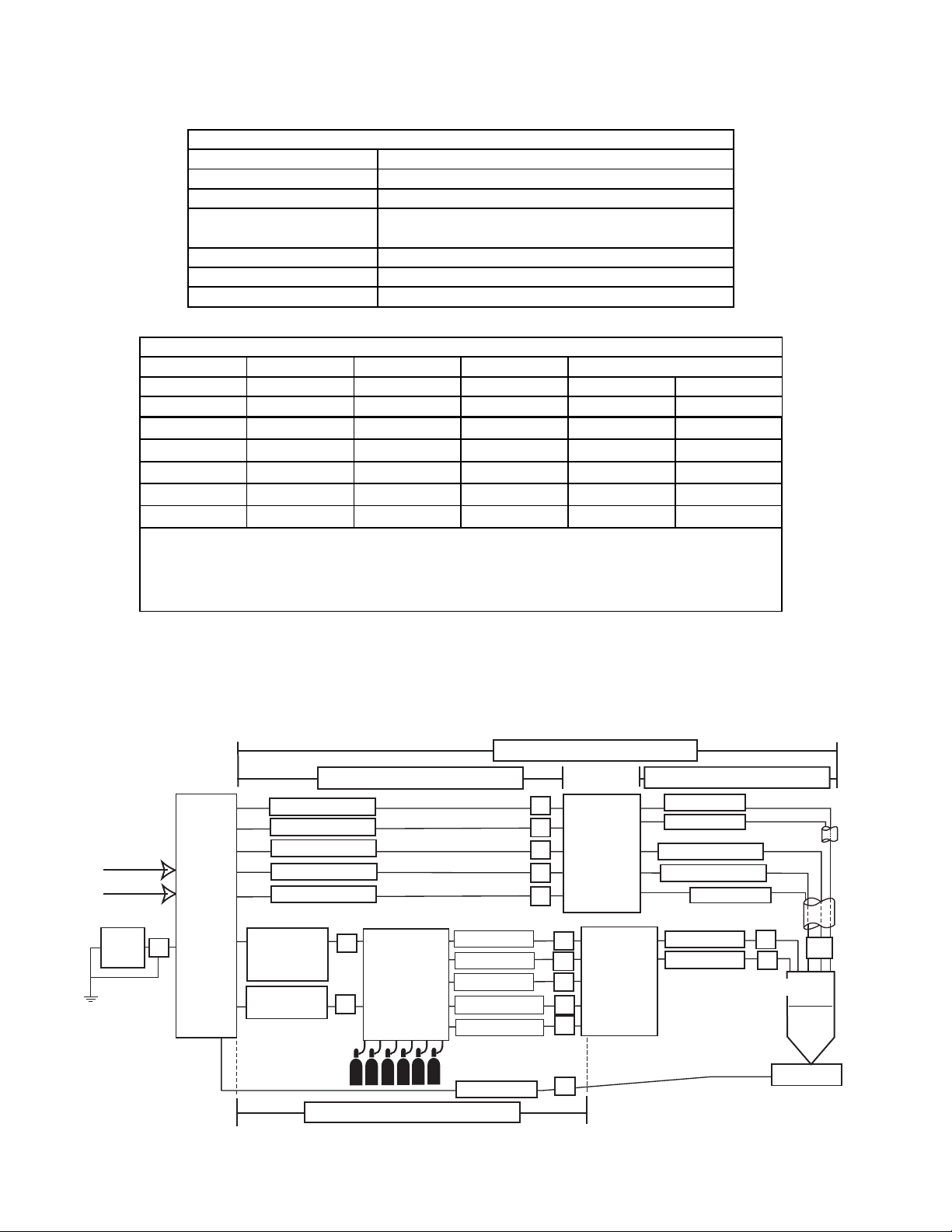
2.06 Specifications & Electrical Requirements
s
Ultra-Cut® 200 Powe r Supply Specifications
Maximum OCV (U0) 380 vdc
Maxim u m O ut p ut Current 200 Amps
Max im um Out put Volt age 230 vdc
Duty Cycle Ratin g
Operating range 14°F to 122°F (-10°C to + 50°C)
Power Factor 0.70 @ 100 ADC Output
Cooli ng Forced A i r (Clas s F )
Ultra-Cut 200 Pow e r S upply Ele ctrical I nput
Input Power Input Current
Volt age Freq. 3-Ph 3-Ph Fus e (Am ps) W ire (A WG)
(Volts ) (Hz ) (kVA) (Amps) 3-Ph 3-Ph
208 60 47 130 160
230 60 49 125 150
400505477100
400 (CE) 50 54 77 100
46060597590
Line Voltages wi t h S ugges ted Circui t P rot ecti on and Wire Si zes
Bas ed on Nati onal E l ectri c Code and Canadian Electri cal Code
1
Extra Hard Usage Type SO, SOW, SOO, SOOW, ST, STW, STO, STOW, STOO, STOOW
2
100% @ 200A, 180vdc (32 kW),
@ 104F° (40°C) Ambient Temperature
Extra Hard Usage Type G, G-GC, W
Sugges t ed S i z es (See Not e)
2
#2
2
#2
1
#2
1
#2
1
#2
2.07 System Component Layout
Refer to section 3.11 for ground connections and ground cables.
175’ / 53.3 m Maximum Length
125’ / 38.1 m Maximum Length
Pilot Return
Negative
Coolant Supply
Primary power
CNC
Art # A-07233_AB
Power
Supply
P
Coolant Return
Control Cable
Fiber
Optic
Cable
Control
Cable
175’ / 53.3 m Maximum Length
L
Gas Control
K
Module
Plasma Gas
Shield Gas
Preflow Gas
Control Cable
Water Shield
Work Cable
100’ / 30.5 m Maximum Length
A
B
C
D
E
H
Q
R
S
T
O
Pilot Return
Remote
Arc
Starter
Torch
Valve
Assembly
Shield
Coolant Supply
Coolant Return
Shield
Plasma Gas
Shield Gas
Positioning Tube
I
J
G
Torch
Work
Manual No. 0-5056 2-2 SPECIFICATIONS
Page 17
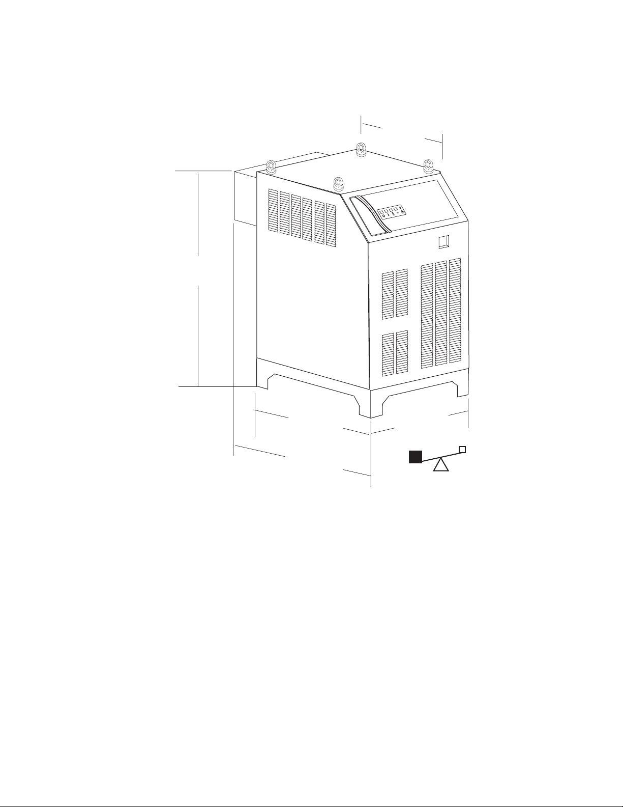
2.08 Power Supply Dimensions
41.25 inch
1050 mm
27 inch
680 mm
Art # A-07182
33 inch
840 mm
37.75 inch
960 mm
27.5 inch
700 mm
433 lb / 196 kg
Manual No. 0-5056 2-3 SPECIFICATIONS
Page 18
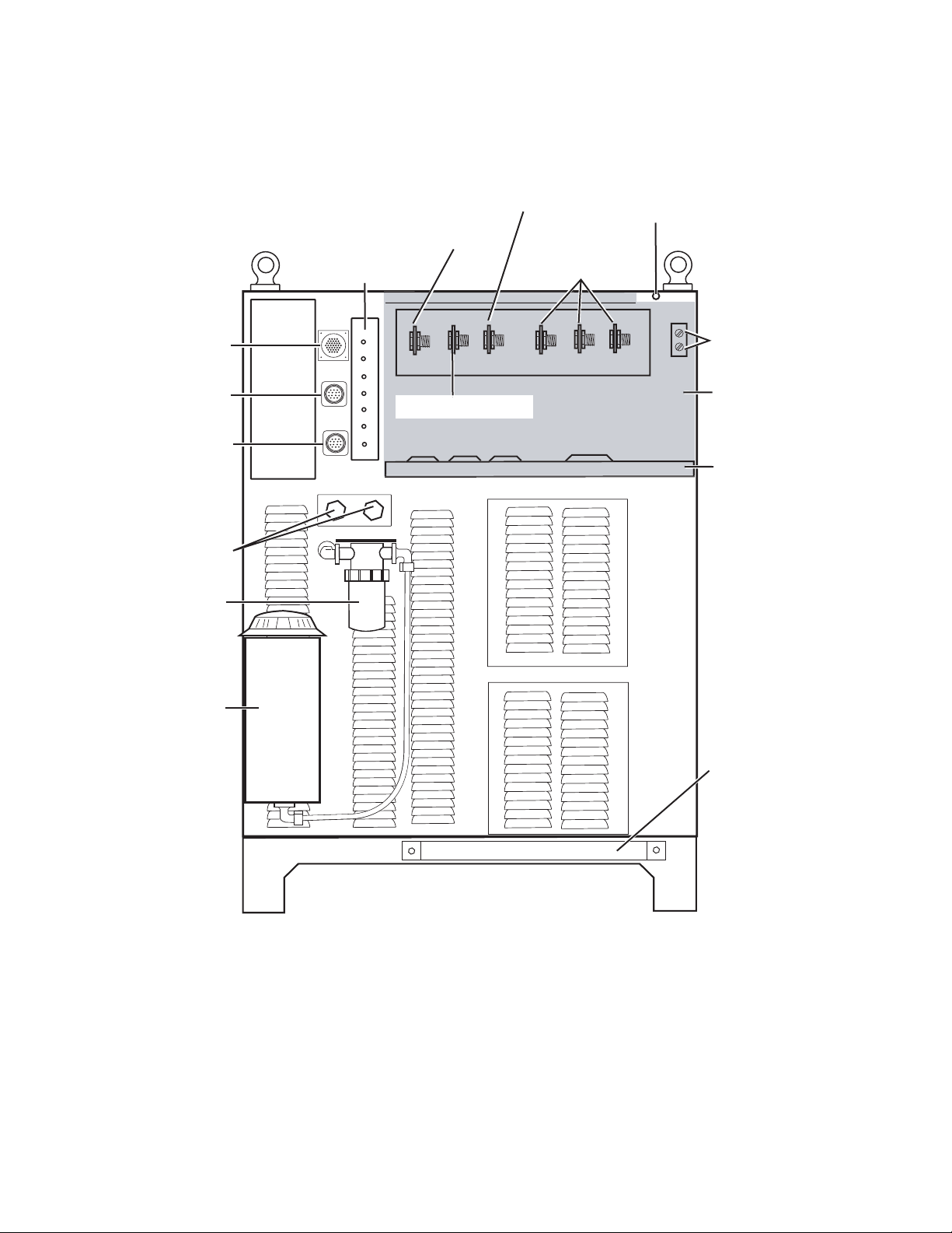
2.09 Power Supply Rear Panel Features
Gas Control
Console Connector
CNC Connector
Remote Arc Starter
Connector
Coolant Connections
Coolant Filter
Pilot (Pos) Terminal
Circuit Breaker
Panel
RETURN
SUPPLY
Torch (Neg) Terminal
AC Power Lamp
Input Power
Terminals
Ground Terminals
Terminal Cover
Work Cable Terminal
Terminal Cover
Support Panel
Coolant Tank
Leads
Bracket
Art # A-04794
Manual No. 0-5056 2-4 SPECIFICATIONS
Page 19

2.10 Gas Requirements
The customer will provide all gases and pressure regulators. Gases must be of high quality. Pressure regulators
shall be double stage.
Ultra-Cut 200 Pow er Supply: Gas Pressures, Fl ows, a nd Qua l i ty Require m ents
Gas Quality Minimum Pressure Flow
O2 (Oxygen)
99.5% P uri t y
(Liquid recom mended)
120 psi
8.3 bar / 827 k Pa
75 scfh (2123 l/h)
99.5% P uri t y
N2 (Nit rog en)
(Liquid recom mended)
<1000 ppm O2, <32
120 psi
8.3 bar / 827 k Pa
180 scfh (5097 l/h)
ppm H2O)
Compressed
or Bottled Air
H35 (Argon-Hydrogen)
H35 = 35% Hy drogen,
65% A rgon
H2O (Wat er) See Note 2
Clean, Dry,
Free of Oil (see Note 1)
99.9 95% P u rity
(gas li quid
recommended)
120 psi
8.3 bar / 827 k Pa
120 psi
8.3 bar / 827 k Pa
50 psi (3. 5 bar)
See Note 3
185 schf (5238 l/h)
85 scfh (2406 l/h)
10 gph (38 lph)
Max i m um Input P ress ure 135 psi (9.3 bar)
Note 1:
The air source must be adequatel y filt ered to rem ove all oi l or grease. Oi l or grease
cont am i nat ion from c om pres sed or bott l ed air c an c ause fires in conjunc t i on with oxygen.
For filtering, a coales cing filter able to filter to 0. 01 mi crons should be ins talled as c lose as
poss i bl e t o t he gas i nl et s on the Gas Control Modul e.
Note 2
: The tap water s ourc e does not need t o be deioni z ed, but i n wat er s ys t em s wit h
ext remel y high mi neral content a wat er s oftener is recom m ended. Tap water with high levels of
partic ul at e m at ter mus t be filtered.
Note 3:
Water Pressure Regulator No. 8-6118 is recommended to ensure
proper wat er pre ss ure .
2.11 Gas Applications
MATERIAL
CUTTING
OUTPUT
FLOW
55 A
100 A
200 A
Manual No. 0-5056 2-5 SPECIFICATIONS
MILD STEEL STAINLESS STEEL ALUMINUM
GAS TYPEGAS TYPE
PLASMA SHIELD
PRE-
PLASMA SHIELD
Air Air Air
Air O
2 Air
GAS TYPE
PRE-
FLOW
Air Air Air Air
PLASMA SHIELD
Air Air
PRE-
FLOW
Air Air Air Air Air Air Air Air Air
Air
O
2
Air
N2 N
N2 H
2 H20N2 N2 H20
35
N
2
N2 H
35
Air Air Air
Air O
2
Air
N
2
Page 20
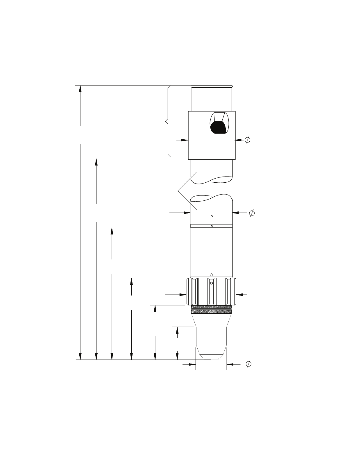
2.12 XTTM-300 Torch Specifications
A. Torch Dimensions
End Cap
Art # A-08301
19.00"
482.68 mm
393.78 mm
15.50"
160.10 mm
6.30"
3.98"
101.1 mm
2.25"
57.15 mm
Mounting Tube
2.0"
50.8 mm
2.39"
60.81 mm
2.63"
66.8 mm
1.57"
39.96 mm
1.49"
37.8 mm
Manual No. 0-5056 2-6 SPECIFICATIONS
Page 21
B. Torch Leads Lengths
Gas Lead Assemblies
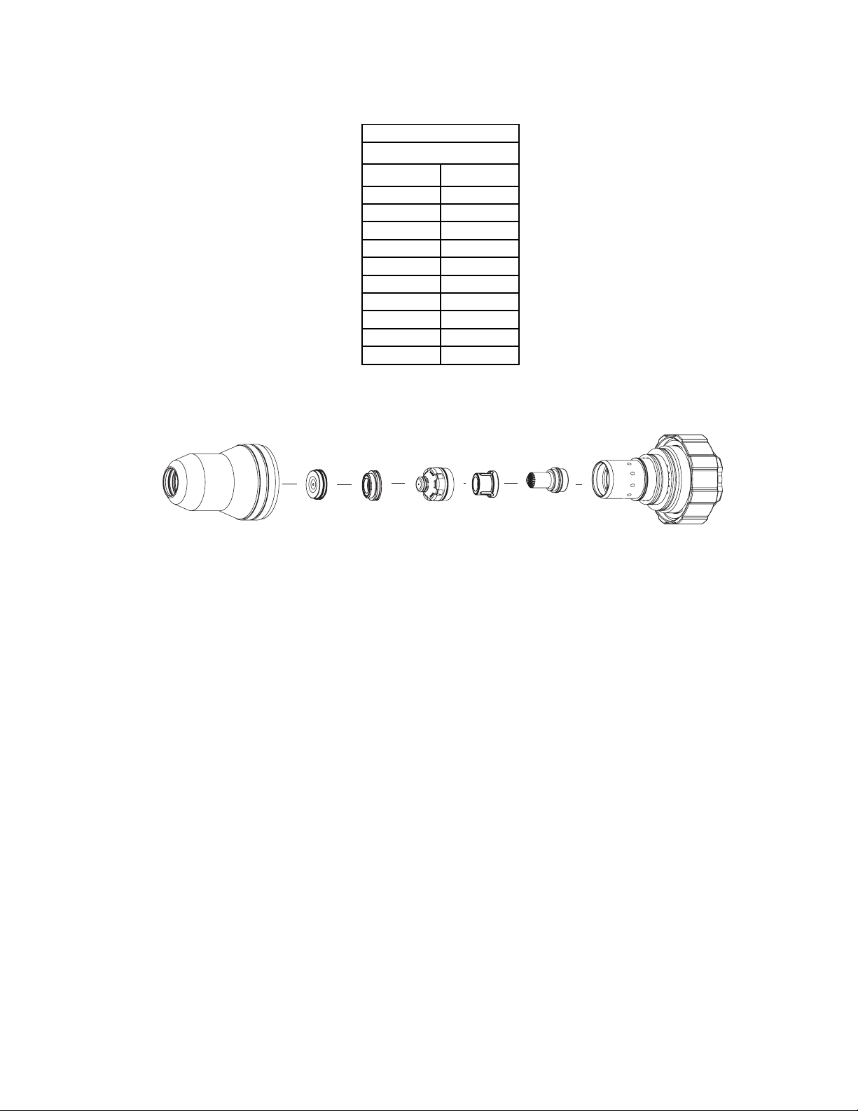
C. Torch Parts (Generic Parts Shown)
Length
Feet Meters
10 3.05
15 4.6
25 7.6
35 10.6
50 15.2
75 22.8
100 30.4
125 38.2
150 45.7
175 53.3
Art # A-04741
Shield Gas
Distributor
Shield Cap
Shield Cup
Tip
Plasma Gas
Distributor
Electrode
Cartridge
D. Parts - In - Place (PIP)
The torch is designed for use with a power supply which senses coolant return flow to confirm that torch
parts are in place. If coolant return flow to the power supply is absent or insufficient the power supply will
not provide power to the torch. Coolant leakage from the torch also indicates that torch parts are absent
or installed improperly.
E. Type of Cooling
Combination of gas stream through torch and liquid cooling.
Manual No. 0-5056 2-7 SPECIFICATIONS
Page 22

F. XTTM-300 Torch Data (with Ultra-CutTM 200 Power Supply)
TM
XT
-300 Torch Ratings
for use wi th Ul tra-Cut 20 0 P o wer Suppl y
Ambient
Tempera ture
Duty Cycl e 100% @ 200 Am ps
Maxi m um Current 150 Am ps
Volt age (V
)500V
peak
Arc Striking Voltage 10kV
Current
TM
XT
-300 Torch Gas Specifications
Plasma Gases:
Shield Gases:
Operating Pres sure
Maxi m um Input P ressure 135 ps i / 9. 3 bar
Gas flow 10 - 300 s cfh
104° F
40° C
Up to 200 Amps, DC,
Straight Polarity
Compress ed Ai r, Oxygen,
Nitrogen, H35
Compress ed Ai r, Oxygen,
Nitrogen, Wat er
125 ps i ± 10 psi
8.6 bar ± 0.7 bar
G. Plasma Power Supply Used With:
• Thermal Dynamics UltraCut® 200
Manual No. 0-5056 2-8 SPECIFICATIONS
Page 23

SECTION 3: INSTALLATION
3.01 Installation Requirements
Electric Supply
The electrical supply network, the gas and water supply system must meet local safety standards. This
conformity shall be checked by qualified personnel.
Ultr a-Cu t 200
Input Power Input Current
Power Supply
Sugges t ed S i z es (See Not e)
Volt age Freq. 3-Ph 3-Ph Fuse (A m ps) Wi re (A WG)
(Volts ) (Hz ) (kVA) (Amps ) 3-Ph 3-Ph
208 60 23 105 125
230602498110
40050285875
400 (CE) 50 28 58 75
46060265775
Line Voltages wi t h S ugges ted Circui t P rot ecti on and Wire Si zes
Bas ed on Nati onal E l ectri c Code and Canadian Electri c al Code
1
Extra Hard Usage Type SO, SOW, SOO, SOOW, ST, STW, STO, STOW, STOO, STOOW
2
Extra Hard Usage Type G, G-GC, W
CAUTION
Fuse and wire sizes are for reference only. The installation must conform to national and local codes for the type
and method of wire being used.
Gas Supply
The customer must supply all gases and pressure regulators. Gases must be of high quality. Pressure
regulators must be double-stage and installed as close as possible to the gas console. Contaminated gas
can cause one or more of the following problems:
#4
#4
#4
#4
#4
2
2
1
1
1
• Reduced cutting speed
• Poor cut quality
• Poor cutting precision
• Reduced consumables life.
• Oil or grease contamination from compressed or bottled air can cause fires in conjunction with oxygen.
Cooling System Requirements
Coolant must be added to the system on installation. The amount required varies with torch leads length.
Thermal Dynamics recommends the use of its coolants 7-3580 and 7-3581 (for low temperatures).
Coolant Capabilit i es
Cat. Number and Mixture Mixture Protects To
TM
7-3580 'Extra-Cool
7-3581 'Ultra-Cool
7-3582 'Ext reme Cool
* For mixing wit h D-I Cool
'
TM
'
TM
' Concent rate* -65° F / -51° C
TM
7-3583
Manual No. 0-5056 3-1 INSTALLATION
25 / 75 10° F / -12° C
50 / 50 -27° F / -3° C
Page 24
3.02 System Layout
Refer to section 3.05 for ground connections and ground cables.
175’ / 53.3 m Maximum Length
Primary power
CNC
Art # A-07233_AB
125’ / 38.1 m Maximum Length
Pilot Return
Negative
Coolant Supply
Power
Supply
P
Coolant Return
Control Cable
Fiber
Optic
Cable
Control
Cable
175’ / 53.3 m Maximum Length
L
Gas Control
K
Module
Plasma Gas
Shield Gas
Preflow Gas
Control Cable
Water Shield
Work Cable
A
B
Remote
C
D
E
H
Q
R
S
T
O
Arc
Starter
Torch
Assembly
100’ / 30.5 m Maximum Length
Pilot Return
Shield
Coolant Supply
Coolant Return
Shield
Plasma Gas
Shield Gas
Valve
Positioning Tube
I
J
G
Torch
Work
Manual No. 0-5056 3-2 INSTALLATION
Page 25
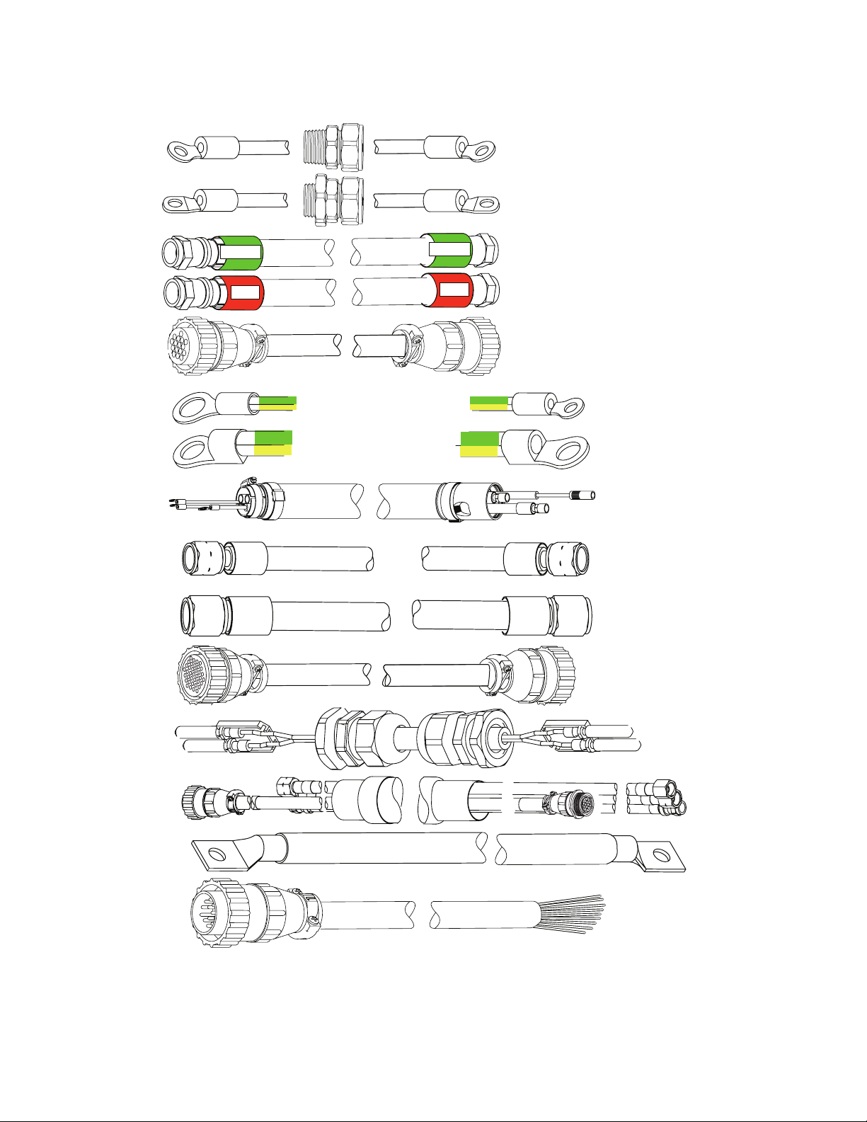
3.03 Cables & Leads Identification
B
D
E
F
F1
#8 AWG Cable
A
#1 AWG Cable
C
14
G
Green
Red
Green / Yellow # 4 AWG
Green / Yellow 1/0 (50 mm )
Green
Red
2
Pilot Return, Power Supply
to Arc Starter
Negative Lead, Power Supply
to Arc Starter
Coolant Supply Lead,
Power Supply to Arc Starter
Coolant Return Lead,
Power Supply to Arc Starter
Control Cable, Power Supply
to Arc Starter
Ground Cable
Ground Cable,
Remote Arc Starter
To Earth Ground
Shielded Torch Lead
Assembly, Remote
Arc Starter to Torch
Art # A-07473
I
J
K
L
H, Q,
R, S,T
O
P
37
14
1/0 Cable (1/0 (50 mm )
Plasma Gas Lead,
Torch Valve to Torch
Shield Gas Lead,
Torch Valve to Torch
Control Cable,
Power Supply to
Gas Control Module
Fiber Optic Cable,
Power Supply to
Gas Control Module
2
CNC Cable (14 Wire)
Work Cable
Manual No. 0-5056 3-3 INSTALLATION
Page 26

3.04 Lift the Power Supply
WARNINGS
Do not touch live electrical parts.
Disconnect input power conductors from de-energized supply line before moving unit.
FALLING EQUIPMENT can cause serious personal injury and equipment damage.
Use all four lifting eyes when using lifting straps to lift the power supply.
Use a forklift, crane, or hoist to lift the unit off the shipping pallet as shown. Keep the power supply steady and
vertical. Do not lift it any further than necessary to clear the shipping pallet.
Art # A-04796
Set the power supply on a solid, level surface. The installer may fasten the power supply to the floor or a
supporting fixture with hardware passing through the horizontal parts of the power supply feet.
Manual No. 0-5056 3-4 INSTALLATION
Page 27
3.05 Remove the Connections Cover
The primary power cable must be supplied by the end user and connected to the power supply.
Remove the connections cover on the rear of the Power Supply. Use caution when removing the panel; there is a
ground wire connected to the inside of the panel. Do not disconnect this wire.
Connections Cover
(Removed)
Connection Panel
Art # A-04797
Manual No. 0-5056 3-5 INSTALLATION
Page 28

Check / Adjust Input Voltage Configuration
1. The power supply includes a voltage configuration board which must be positioned to match the primary
input voltage. Remove the power supply left side panel and locate the voltage configuration board. The input
voltage configuration is shown at the top of the board.
2. If necessary, disconnect the jumper at the top right corner of the board, remove the board and re-install it with
the correct input voltage shown at the top of the board.
3. Re-connect the jumper. Re-install the power supply side panel.
Inverter Module
1. Disconnect jumper
208/230V / 460V
Input Voltage Board
(Shown in 460V Position)
2. Remove bolts.
3. Invert board.
4. Re-install board.
5. Connect jumper.
Art # A-04856
Manual No. 0-5056 3-6 INSTALLATION
Page 29

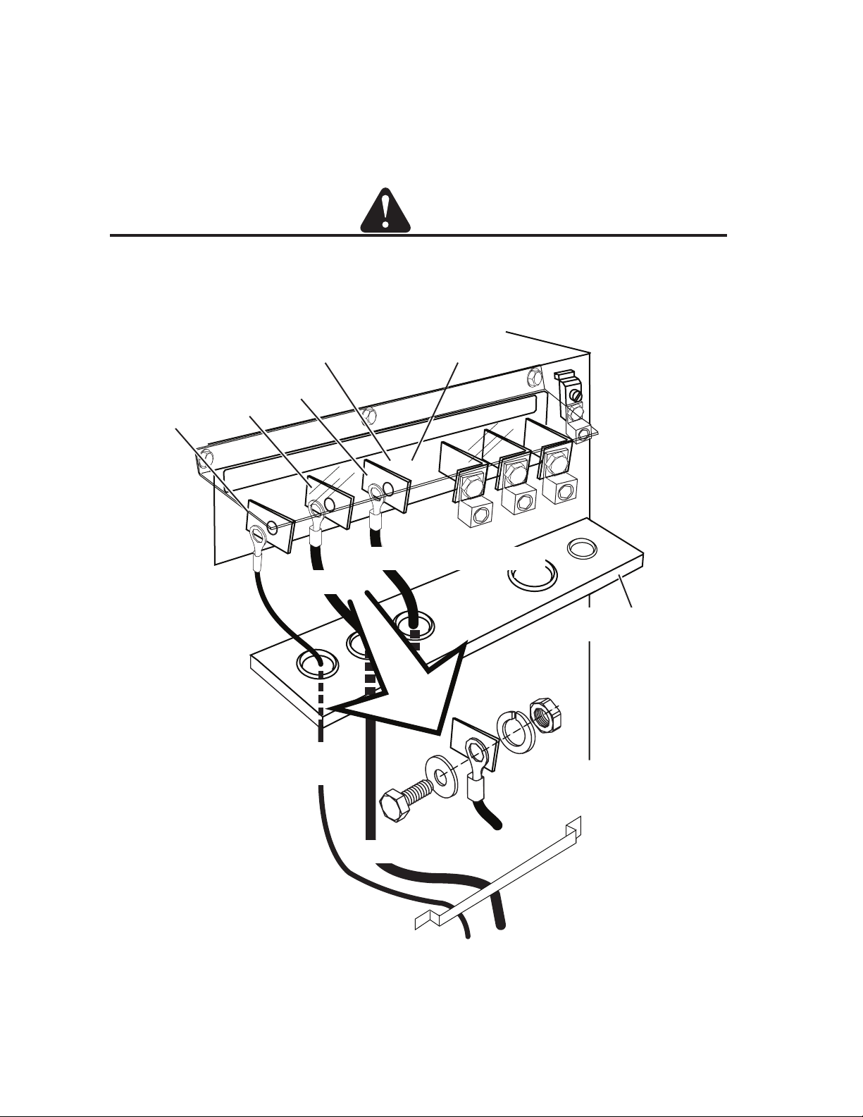
Connect Input Power and System Ground Cables
1. Carefully cut back the outer sheath on the primary input power cable to expose the individual cords. Cut back
the insulation on the individual cords. Route the cable upward through leads bracket at the bottom of the rear
panel, then through the connections cover support panel on the rear panel of the power supply.
2. Install ring tongue terminals on the individual cords. Fasten the terminals to the individual cords securely.
3. Connect the individual cords as shown. Connect the power cable ground cord to the ground terminal block.
CAUTION
The clear connections cover must remain in place.
4. If required pass a system ground cable (F1) through the last opening in the connections cover support panel
next to the input power cable. Connect the cable to the ground terminal block on the power supply rear panel.
Refer to the Ground Connections Section for full details and procedures on proper system grounding.
Ground Terminal Block
Connections Cover
Connection Panel
AC INPUT
to Remote Arc Starter
L1 L2 L3
PILOT
Art # A-07659_AB
WORK TORCH
to Remote Arc Starter
L2
L1
Input power cable
L3
System Ground Cable
Input power cable ground
Connections Cover
Support Panel
System Ground Cable
Leads Bracket
5. Re-install the connections cover on the power supply. Snug the hardware securely by hand. Do not overtighten.
Manual No. 0-5056 3-7 INSTALLATION
Page 30

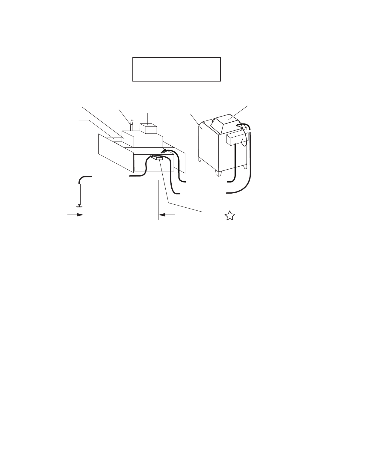
Star Ground on Cutting Table
Ultra-Cut
or
Auto-Cut O2
Remote Arc
Starter (RAS-1000)
Cutting Machine / Gantry
Cutting Table
1/0
Ground Cable
(F1)
Customer supplied
Earth Ground
Rod
Torch
1/0
Ground Cable
0 - 10 ft (0 - 3 m) Ideal
20 ft (6 m) Maximum
CNC
Device
Star Ground on Cutting Table
Gas Control Module
Primary location
#4 AWG
Ground
(F)
1/0 Work Cable
1/0 Ground Cable
Power Supply
‘Star’
Ground
Note: The gas control module can
be mounted on top of the power
supply.
If it is, it should be grounded
directly to the power supply with
#4 AWG ground, (F).
This alternate location requires
grounding the power supply to the
‘Star’ ground with the 1/0 Ground
Cable (F1).
Remote Arc
Starter (RAS-1000)
Cutting Machine / Gantry
Cutting Table
1/0
Ground Cable
(F1)
Ground Cable
Customer supplied
Earth Ground
Rod
Torch
1/0
0 - 10 ft (0 - 3 m) Ideal
20 ft (6 m) Maximum
CNC
Device
Gas Control Module
Power Supply
1/0 Work Cable
‘Star’
Ground
Auto-Cut W/RAS
#4 AWG Ground (F)
(Factory Installed)
Art # A-08253_AC
Manual No. 0-5056 3-8 INSTALLATION
Page 31
Auto-Cut Basic System
Without RAS
Cutting Machine / Gantry
Cutting Table
Ground Cable
Customer Supplied
Earth Ground
Rod
Torch
1/0
0 - 10 ft (0 - 3 m) Ideal
20 ft (6 m) Maximum
CNC
Device
Auto-Cut
Power Supply
1/0 Work Cable
1/0 Ground Cable
(F1)
‘Star’
Ground
GCM-1000
Gas Control Module
#4 AWG Ground (F)
(Factory Installed)
Art # A-08254_AC
Manual No. 0-5056 3-9 INSTALLATION
Page 32

3.06 Ground Connections
A. Electromagnetic Interference (EMI)
Pilot arc starting generates a certain amount of electromagnetic interference (EMI), commonly called RF noise.
This RF noise may interfere with other electronic equipment such as CNC controllers, remote controls, height
controllers, etc. To minimize RF interference, follow these grounding procedures when installing mechanized
systems:
B. Grounding
1. The preferred grounding arrangement is a single point or “Star” ground. The single point, usually on the cutting
table, is connected with 1/0 AWG (European 50 mm2) or larger wire to a good earth ground (measuring leass
than 3 ohms; an ideal ground measures 1 ohm or less. Refer to paragraph ‘C’, Creating An Earth Ground. The
ground rod must be placed as close as possible to the cutting table, ideally less than 10 ft (3.0 m), but no more
than 20 ft (6.1 m) from the cutting table.
NOTE
All ground wires should be as short as possible. Long wires will have increased resistance to RF
frequencies. Smaller diameter wire has increased resistance to RF frequencies, so using a larger
diameter wire is better.
2. Grounding for components mounted on the cutting table (CNC controllers, height controllers, plasma remote
controls, etc.) should follow the manufacturer’s recommendations for wire size, type, and connection point
locations.
For Thermal Dynamics components (except Remote Arc Starter and Gas Control Module) it is recommended
to use a minimum of 10 AWG (European 6 mm2) wire or flat copper braid with cross section equal to or greater
than 10 AWG connected to the cutting table frame. The Remote Arc Starter uses 1/0 earth ground wire and the
Gas Control Module should use minimum # 4 AWG wire. The connection point must be to clean bare metal; rust
and paint make poor connections. For all components, wires larger than the recommended minimum can be
used and may improve noise protection.
3. The cutting machine frame is then connected to the “Star” point using 1/0 AWG (European 50 mm2) or larger
wire.
4. The plasma power supply work cable (see NOTE) is connected to the cutting table at the single point “Star” ground.
NOTE
Do Not connect the work cable directly to the ground rod.
5. Make sure work cable and ground cables are properly connected. The work cable must have a solid connection
to the cutting table. The work and ground connections must be free from rust, dirt, grease, oil and paint. If
necessary grind or sand down to bare metal. Use lock washers to keep the connections tight. Using electrical
joint compound to prevent corrosion is also recommended.
6. The plasma power supply chassis is connected to the power distribution system ground as required by electrical codes. If the plasma supply is close to the cutting table (see NOTE) a second ground rod is not usually
needed, in fact it could be detrimental as it can set up ground loop currents that cause interference.
When the plasma power supply is far away from the ground rod and interference is experienced, it may help to
install a second earth ground rod next to the plasma power supply. The plasma power supply chassis would
then be connected to this ground rod.
NOTE
It is recommended that the Plasma Power Supply be within 20 - 30 ft (6.1 – 9.1 m) of the cutting table,
if possible.
7. The plasma control cable should be shielded with the shield connected only at the cutting machine end.
Connecting the shield at both ends will allow ground loop currents which may cause more interference than with
no shield at all.
Manual No. 0-5056 3-10 INSTALLATION
Page 33
Creating An Earth Ground
1. To create a solid, low resistance, earth ground, drive a 1/2 in (12 mm) or greater diameter copper clad ground
rod at least 6 - 8 ft (1.8 - 2.4 m) into the earth so that the rod contacts moist soil over most of its length.
Depending on location, a greater depth may be required to obtain a low resistance ground (see NOTE). Ground
rods, typically 10 ft (3.0 m) long, may be welded end to end for greater lengths. Locate the rod as close as
possible to the work table. Install a ground wire, 1/0 AWG (European 50 mm2) or greater, between the ground
rod and the star ground point on the cutting table.
NOTE
Ideally, a properly installed ground rod will have a resistance of three ohms or less.
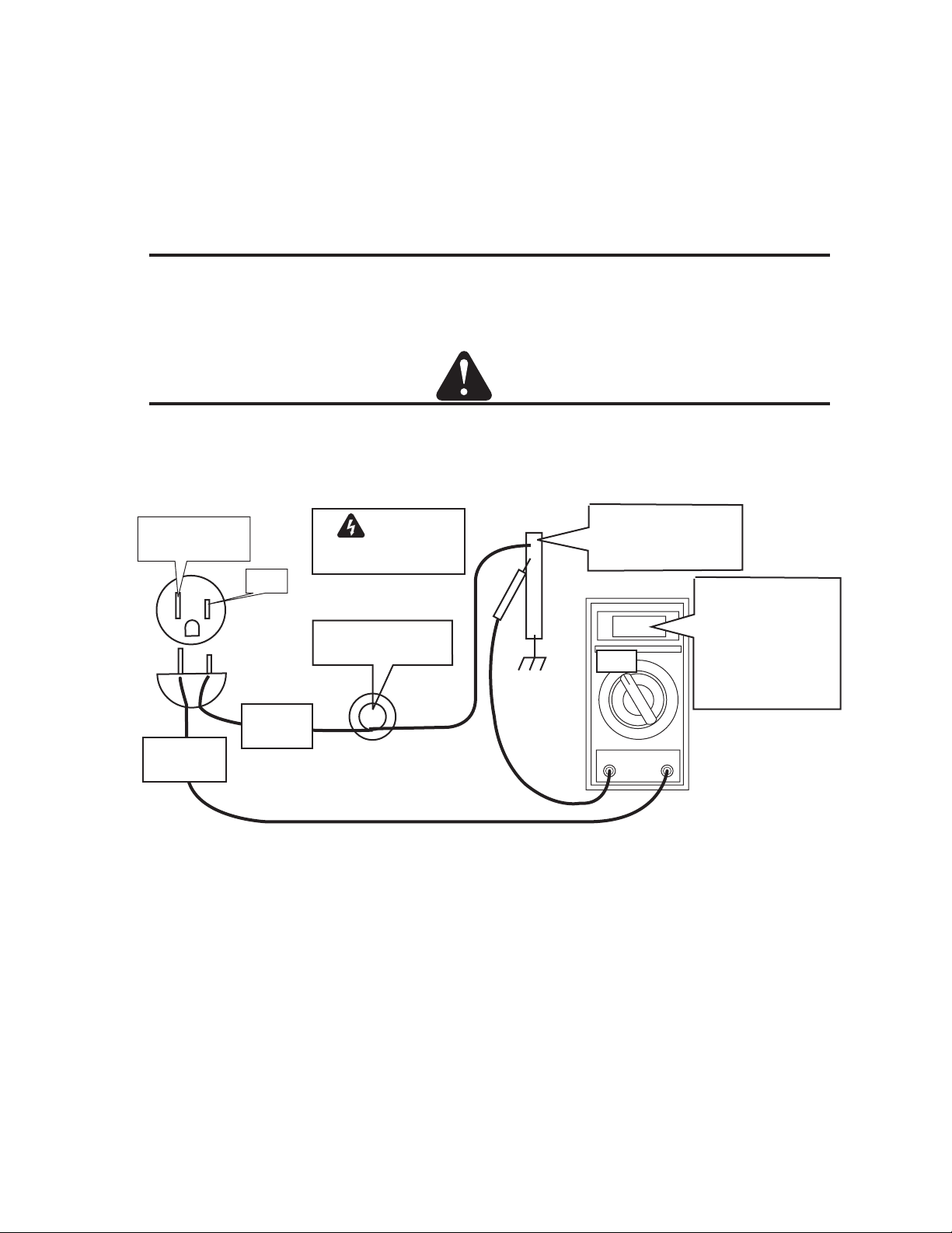
To test for a proper earth ground, refer to the following diagram. Ideally, the reading on the multimeter should be as
shown.
CAUTION
No other connections should be made at the ground rod being tested.
This test assumes the 115 or 230 VAC source neutral is connected to the utility earth ground.
NEUTRAL
Earth Grounded
NEUTRAL
PROBE
WARNING
Use extreme caution. This
test uses live voltage.
HOT
100W Incandescent
light bulb*
HOT
PROBE
* Can replace light bulb with
a 100w resistor.
Use 100 ohm for 115VAC.
Use 500 ohm for 230VAC
Ground Rod
with other
connections removed
On 115V AC Line:
3VAC = 3 ohms
1VAC = 1 ohm
VAC
On 230V AC Line:
1.5VAC = 3 ohms
0.5VAC = 1 ohm
Art # A-07252
Ground Testing
2. Increasing the ground rod length beyond 20 - 30 ft (6.1 – 9.1 m) does not generally increase the effectiveness
of the ground rod. A larger diameter rod which has more surface area may help. Sometimes keeping the soil
around the ground rod moist by continuously running a small amount of water into it will work. Adding salt to the
soil by soaking it in salt water may also reduce its resistance. When these methods are used, periodic
checking of the ground resistance is required to make sure the ground is still good.
D. Routing Of Torch Leads
1. To minimize RF interference, position torch leads as far as possible from any CNC components, drive motors,
control cables, or primary power lines. If cables have to pass over torch leads, do so at an angle. Do not run the
plasma control or other control cables in parallel with the torch leads in power tracts.
2. Keep torch leads clean. Dirt and metal particles bleed off energy, which causes difficult starting and increased
chance of RF interference.
Manual No. 0-5056 3-11 INSTALLATION
Page 34
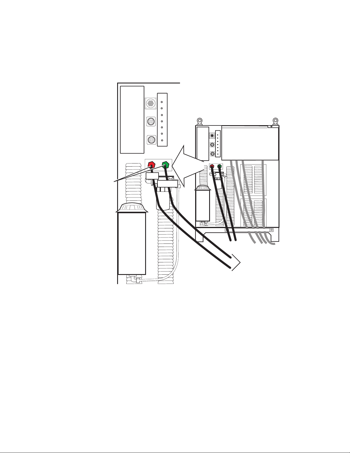
3.07 Connect Work Cable and Pilot and Negative Leads
1. Pass the ends of the work cable and pilot and negative leads upward through the leads bracket at the
bottom edge of the rear panel, then through the openings in the connections cover support panel.
2. Refer to the illustration. Connect the leads as shown. Tighten securely. Do not overtighten.
CAUTION
The clear connections cover must remain in place.
Pilot
Connections Cover
Torch
Work
PILOT WORK TORCH
Work Lead
Pilot Lead To Remote Arc Starter
Connection Panel
Torch Lead -
AC INPUT
L1 L2 L3
To Remote Arc Starter
Connections Cover
Support Panel
Lead Connection Detail
Art # A-07660_AB
To Cutting Table
Leads Bracket
Manual No. 0-5056 3-12 INSTALLATION
Page 35
3.08 Connect Coolant Leads
1. Connect the color-coded coolant hoses to the coolant connections on the power supply rear panel. The
supply line (out) is flagged green, the return line (in) is flagged red.
COOLANT
RETURN
SUPPLY
RETURN
SUPPLY
Coolant Connections
RED
GREEN
To Remote Arc Starter
Art # A-04800
Manual No. 0-5056 3-13 INSTALLATION
Page 36
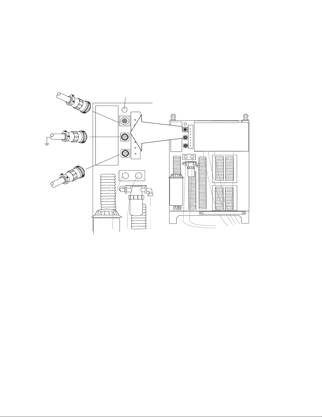
3.09 Connect Control Cables for CNC, Remote Arc Starter, and GCM
1. Connect one end of each cable to the power supply.
2. Connect the other end of the CNC cable to the CNC device.
3. The CNC cable shield must be attached to ground.
Customer Wiring
Access Hole
To Gas Control Module
To CNC
To Remote Arc Starter
RETURN
SUPPLY
Art # A-04802
Manual No. 0-5056 3-14 INSTALLATION
Page 37
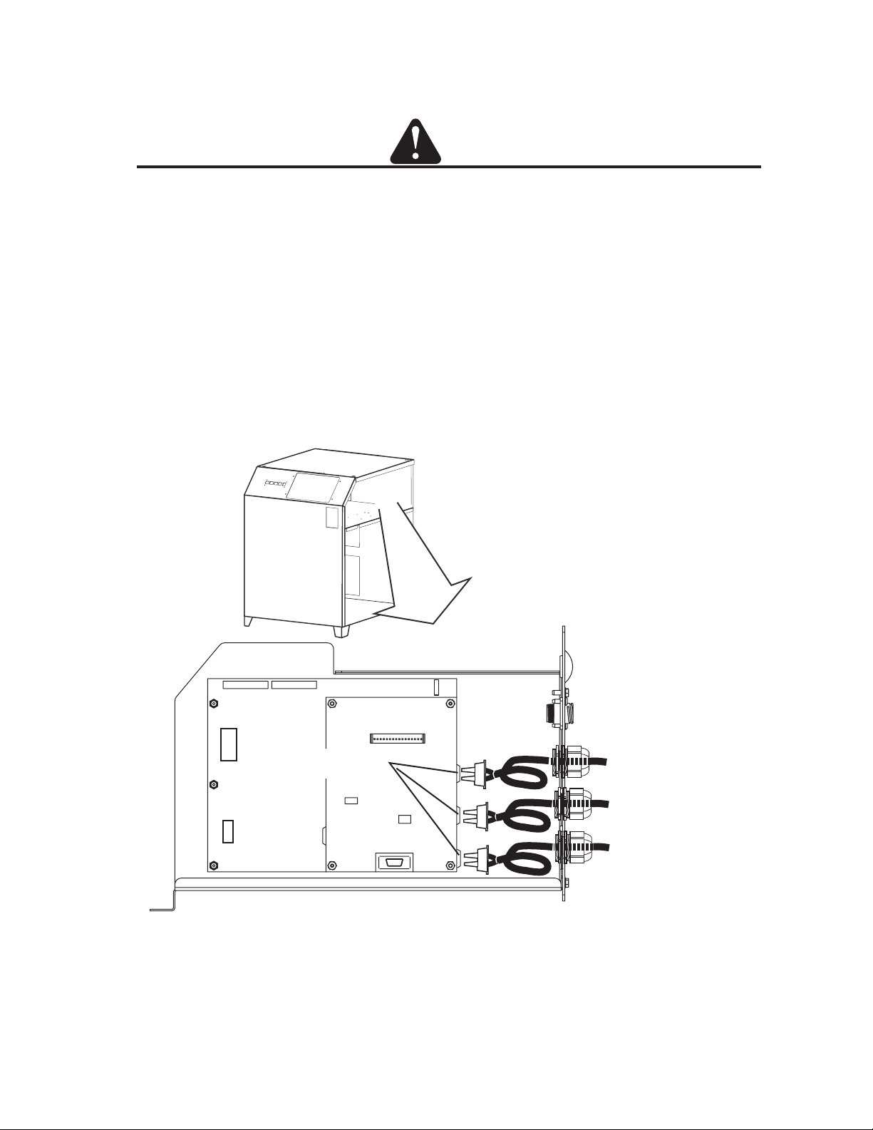
3.10 Connect Fiber Optic Cable (Type 2 internal control module)
CAUTION
Check the type of internal control module. Use this section for connections to an internal control module without
an external connections cover. Use the preceding section for connections to an internal module with an external
connections cover.
1. Connect one end of each cable to the power supply as shown.
a. Remove the strain relief securing nut from the strain relief on the fiber optic cable(s). Loosen the strain
relief dome nut from the strain relief.
b. Pass the cable connector through the appropriate opening. Slide the strain relief securing nut onto the
cable. Make a loop of the cable; carefully press the cable connector into the appropriate receptacle on the
internal control module.
c. Tighten the strain relief onto the cable(s). Do not overtighen.
Cable Receptacles
Profile Detail, Fiber Optic Cable Installation
To Gas Control Module
To Remote HMI
(if installed)
To Slave Power
Supply
(if installed)
Art # A-06793
Manual No. 0-5056 3-15 INSTALLATION
Page 38

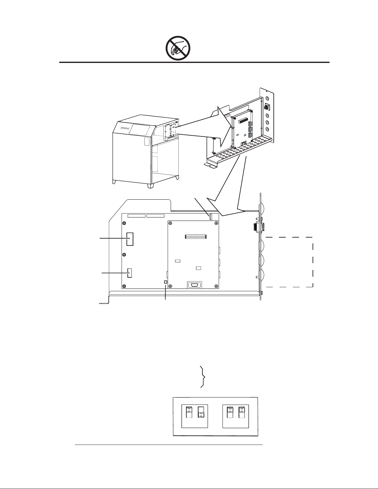
3.11 Set Switches on the Command - Control Module (Type 2 Module)
Compare the command - control module to the illustration. Follow instructions in this section for a module
without an external connection cover.
Remove the power supply right side. Set switches on the CCM (Command-Control Module) per the illustrations.
Switch settings and connection details are provided in the Appendix.
CAUTION
Printed circuit boards in the Command - Control Module are static - sensitive. Discharge any built-up static
charges in your body or surroundings before touching the printed circuit boards.
Future Use
O
N
SW-1-1: Auto Pilot Restart. 1 = ON = Auto Pilot Function enabled.
1 = OFF = Auto Pilot Function disabled (Factory default setting).
SW-1-2: Pilot Delay 2 = OFF, 3 = OFF, 4 = OFF: 0 Seconds (Factory default setting).
SW-1-3: Pilot Delay 2 = ON, 3 = OFF, 4 = OFF: 0.1 Seconds
SW-1-4: Pilot Delay 2 = OFF, 3 = ON, 4 = OFF: 0.2 Seconds
2 = ON, 3 = ON, 4 = OFF: 0.4 Seconds
2 = OFF, 3 = OFF, 4 = ON: 0.8 Seconds
2 = ON, 3 = OFF, 4 = ON: 1.0 Seconds
2 = OFF, 3 = ON, 4 = ON: 1.5 Seconds
2 = ON, 3 = ON, 4 = ON: 2.0 Seconds
SW-3: Gas Preflow Time 1 = Off, 2 = OFF: 2 seconds
1 = ON, 2 = OFF: 4 seconds
1 = OFF, 2 = ON: 6 seconds
1 = ON, 2 = ON: 8 seconds
SW-4: Postflow Time 1 = OFF, 2 = OFF: 10 Seconds (Factory default setting).
1 = ON, 2 = OFF: 20 Seconds
1 = OFF, 2 = ON: 5 Seconds
1 = ON, 2 = ON: 0 Seconds
SW-5-1: Tip Saver 1 = OFF = Disabled (Factory default setting).
1 = ON = Enabled
SW-5-2: Off Plate 2 = OFF = Disabled (Factory default setting).
2 = ON = Enabled
SW 8-1: Pilot Time 1 = OFF = Short (85 ms.) (Factory default setting).
1 = ON = Long (3 s.)
SW 8-2: Remote Current 1 = ON (Remote Analog Current Control)
SW 8-3, SW 8-4: Reserved for Factory use.
SW1
1
3
2
SW3
1
4
2
1
SW4
SW5
1
2
2
SW8
4
1
3
2
1
O
N
2
Active only when
SW-1-1 is set to O
Art # A-06791
N.
Manual No. 0-5056 3-16 INSTALLATION
Page 39
CAUTION
Printed circuit boards in the Command - Control Module are static - sensitive. Discharge any built-up static
charges in your body or surroundings before touching the printed circuit boards.
SW11
SW6
No external
connection cover
SW12
SW13
SW-6: OK-to-Move: Contact closure, 120VAC @ 1A (Factory default setting) or
DC Volts (16-18vdc@ up to 100 ma.)
SW-11: Analog Current Control. B = from Gas Control (Factory default setting) or A = from CNC.
Position A requires that SW-8-2 be ON.
SW-12-1/2/3/4: Divided Arc signal
1 = ON = 16.6:1
2 = ON = 30:1
3 = ON = 40:1
4 = Not used.
SW13: TVA and XTL Switch positions
All = OFF = 50:1 (Factory default setting)
Only 1 on at a time.
Art # A-06792
1
2
TVA XTL TVA
SW13
1
2
Manual No. 0-5056 3-17 INSTALLATION
Page 40

3.12 Height Control Connections
The terminal strip has Arc Volts (-) connection to power supply negative output TORCH terminal, Arc Volts (+)
connection to power supply positive output WORK terminal. These are for a height control that requires
connection to the full non-divided arc voltage. Also available on the terminal strip are 120VAC (120,0) and 24
VAC (24, 0). Note that the two 0’s are not common. The allowable current draw is 100ma @ 120VAC and 1Amp
@ 24 VAC.
There is also a hole added in the rear panel above the J55-GCM receptacle for customer wiring. This, rather
than the one in the CCM will be the preferred place for customer added wiring (and strain relief) for connections to height controls, etc..
Manual No. 0-5056 3-18 INSTALLATION
Page 41
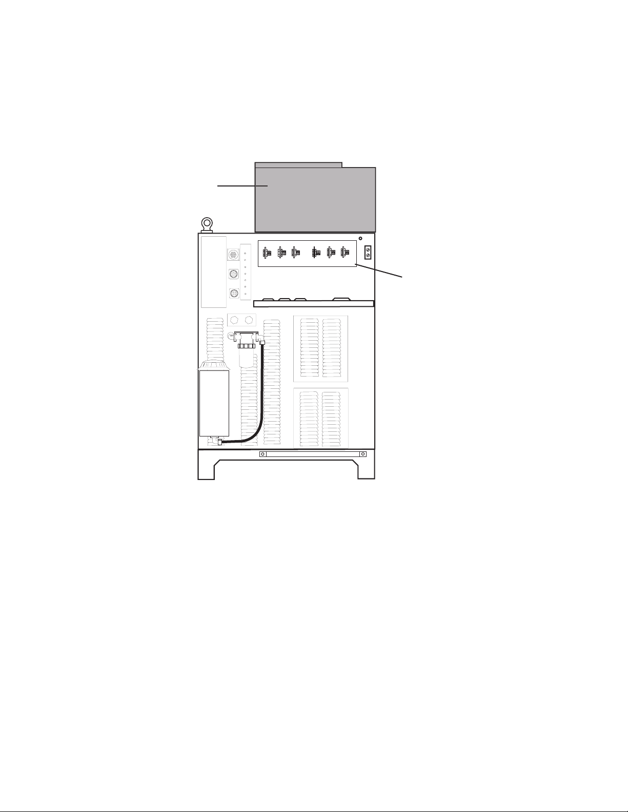
3.13 Gas Control Module Installation
The Gas Control Module must be installed in a suitable location where it is easily accessible to the system
operator. The unit must be mounted to a flat horizontal surface. If the Module is mounted to a gantry or to any other
support subject to vibration or motion, the installer must fasten the module to the support securely.
The Module should be located aas far away as possible from the Arc Starter due to electromagnetic interference.
It is acceptable to locate the control cable in the same track as the cables from the Arc Starter.
The Module includes feet which lift the bottom panel off the mounting surface. There are ventilation holes on the
bottom panel; the space between the bottom panel and the mounting surface must remain open for ventilating air
to enter the module. Louvers on the back panel of the module must also remain unblocked, for the free passage
of ventilating air.
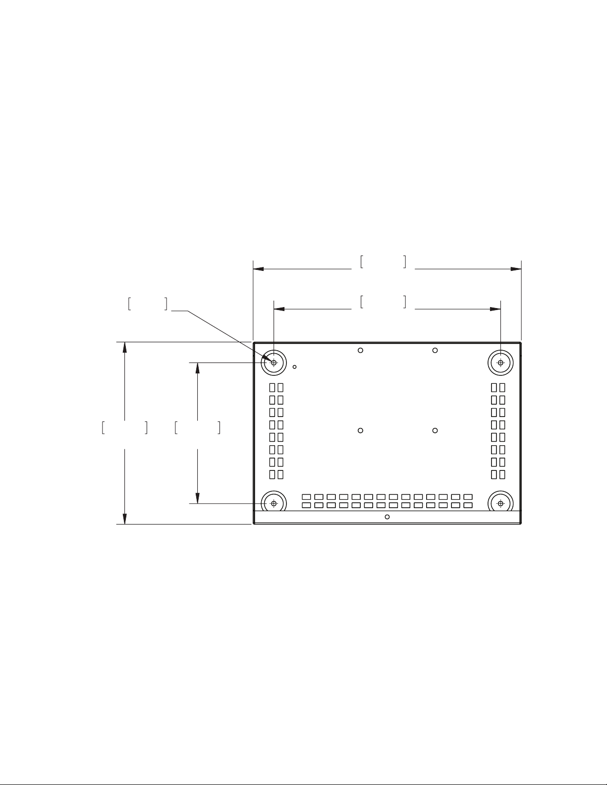
Mounting Dimensions
Gas Box
7.14mm
0.28”
279.40mm
11.00”
410.97mm
16.18”
347.47mm
13.68”
215.90mm
8.50”
Art # A-07962
Manual No. 0-5056 3-19 INSTALLATION
Page 42

NOTE
The unit must be mounted so that the Flowmeters are plumb. If the Flowmeters are not plumb, incorrect
flow indications may occur.
Preparation
1. Remove the screws securing the Cover Panel to the Module.
2. Carefully remove the cover from the module noting the attached ground wire. Remove the ground wire if
needed.
Gas Control Module Cover
Remove Ground
Wire
Do not remove
Art # A-06882
Cover Removal
Manual No. 0-5056 3-20 INSTALLATION
Page 43
3.14 Fiber Optic Cable Installation
1. Install the through-hole protector for the fiber-optic cable in the hole in connection panel on the back of the
Module.
2. Pass the fiber-optic cable connector through the hole in connection panel on the back of the Module. Pass
enough of the cable into the Module to allow the cable to loop upward as shown.
CAUTION
Avoid kinking, twisting, or bunching the fiber optic cable. The cable can be damaged by being forced
into tight-radius turns.
Circuit Board
2
3
Fiber Optic Cable
Art # A-04772
PLASMA
OUT
SHIELD
OUT
PREFLOW
OUT
2
H
COMM
J56
J57
POWER
SUPPLY
F5
TVA
H35
2
INPUTS
O
2
AIR N
O
LOW
PREF
SMA
PLA
2
INPUTS
SHIELD
O
2
H
SHIE
O
2
N
AIR
O
2
H
LD
1
COMM
J56
J57
POWER
Y
SUPPL
F5
A
TV
H35
Manual No. 0-5056 3-21 INSTALLATION
Page 44

3. Insert the fiber-optic cable connector into the receptacle on the vertically-mounted circuit board as shown.
Circuit Board
Fiber Optic Cable
Art # A-04773
4. Tighten the through-hole protector for the fiber-optic cable.
5. Reinstall the Cover Panel making sure the ground wire is attached.
Manual No. 0-5056 3-22 INSTALLATION
Page 45

3.15 Gas Control Module: Control, Input, and Output Connections
1. Make all other connections to the rear of the Module. The connections are labeled. The Module must be
grounded; the grounding terminal is marked Use #10 AWG (European 6 mm2) (or thicker) wire for
grounding. Keep the ground wire as short as possible.
2. Position the Module on a flat, horizontal, mounting surface.
3. Ensure that the Flowmeters are plumb.
4. Secure the Module to the mounting surface.
5. Connect all gas / water inputs to the rear panel of the module.
6. Connect the appropriate control cables to terminals marked ‘TVA’ (torch valve assembly) and ‘power sup-
ply’.
SHIELD PLASMA
H O
2
SHIELD
To Torch Valve Assembly
H O
2
PREFLOW
To Torch Valve Assembly
J57
When Cutting With O2 Plasma
Air MUST BE Connected
AIR
INPUTS
N2
O2
H35
Gas & Water Inputs (Check Valves)
TVA
To Power Supply
J56
POWER
SUPPLY
F5
Ground Stud
COMM
Gas Control Box
Rear Panel
J56
Connection Panel
SHIELD PLASMA
H O
2
SHIELD
H O
2
PREFLOW
When Cutting With O2 Plasma
Air MUST BE Connected
INPUTS
AIR
N2
J57
TVA
H35
O2
COMM
POWER
SUPPLY
F5
Art # A-06881
Manual No. 0-5056 3-23 INSTALLATION
Page 46

3.16 Install Remote Arc Starter
Site Location
Select a clean, dry location with good ventilation and adequate working space around all components.
Review the safety precautions in the front of this manual to be sure that the location meets all safety requirements.
Interconnecting cables and hoses attach to the Arc Starter. There must be adequate space around the Arc Starter
for these connections without crimping.
Mounting Dimensions
304.80mm
12.00”
12.70mm
.50”
Arc Starter Box
6.35mm
D.250”
3 PLACES
203.20mm
8.00”
50.80mm
2.00”
190.83mm
7.51”
37.77mm
1.49”
Art # A-07961
Manual No. 0-5056 3-24 INSTALLATION
266.70mm
10.50”
Page 47

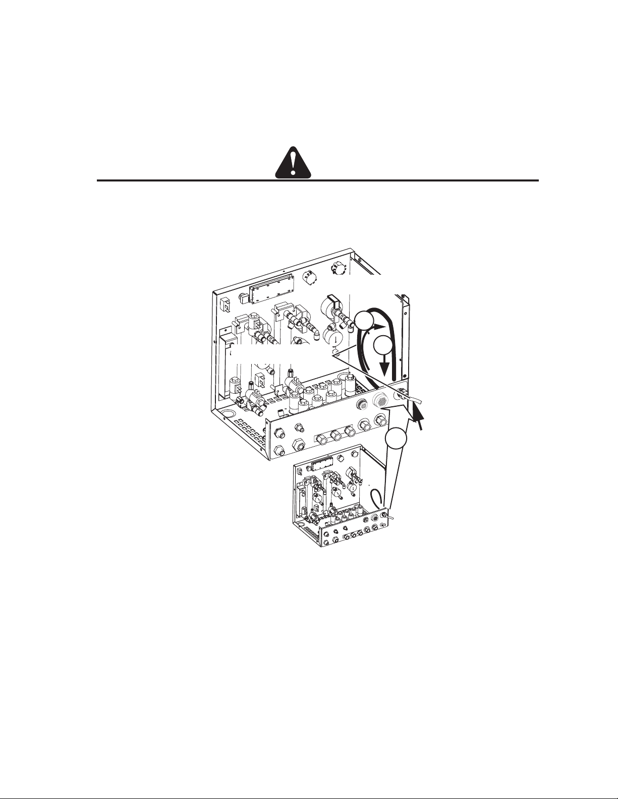
Installation
The Remote Arc Starter must be installed in a suitable location near the torch head. If the Arc Starter is mounted
to a gantry or to any other support subject to motion or vibration, fasten the Arc Starter to the support securely.
1. Loosen, but do not remove, the lower screws securing the cover to the Arc Starter. Remove the upper
screws securing the Cover Panel to the Arc Starter.
NOTE
A ground wire connects the cover to the Arc Starter base. This wire must remain in place.
2. Remove the Cover Panel from the Arc Starter.
Upper screws (4 per side)
Cover
Ground Wire
Lower screws
Art # A-07029
Cover Removal
3. Position the Arc Starter on a flat, horizontal mounting surface.
Manual No. 0-5056 3-25 INSTALLATION
Page 48
4. Use pre-drilled holes in at least two of the feet on the bottom of the Arc Starter to secure the Arc Starter to the
mounting surface.
Minimum 2
Art # A-04749
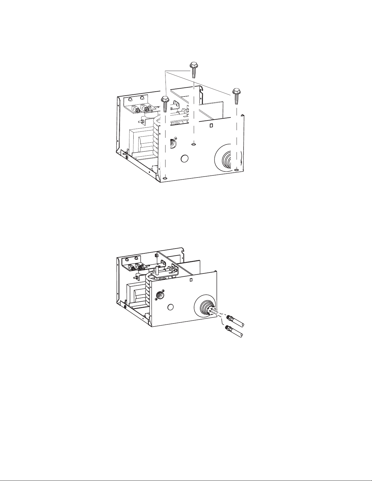
Input Connections
1. Refer to the illustrations. Make the following input connections to the Arc Starter.
• Coolant Supply and Return Hoses (from power supply). Hoses and connectors are color-coded; Red
for Return, Green for Supply.
Art # A-04750
Coolant Supply and Return Hoses
(from power supply)
Manual No. 0-5056 3-26 INSTALLATION
Page 49

Art # A-04751
Green
Coolant Supply (Green)
Coolant Return (Red)
Red
Coolant
Return
(Red)
Art # A-04752
Negative Cable
from power supply
Negative Cable (from Power Supply rear panel)
Manual No. 0-5056 3-27 INSTALLATION
Page 50
Art # A-04753
Pilot Return Cable
from Power supply
PILOT Return Cable (from Power Supply rear panel)
Art # A-04755
Control Cable from Power Supply rear panel
Manual No. 0-5056 3-28 INSTALLATION
Page 51

Output Connections
1. Refer to the illustrations. Make the following output connections to the Arc Starter.
Inner Shield Lead
Pilot Lead
Inner Shield
Connection Detail
Art # A-04933
Pilot Lead
Connection Detail
Pilot Return Cable and Inner Shield Lead (from Torch Leads)
Manual No. 0-5056 3-29 INSTALLATION
Page 52
Art # A-04757
Some items are removed
for clarity.
Coolant Return Fitting
(Tagged with Red)
Coolant Supply Fitting
(Tagged with Green)
Coolant Supply
(Green) to Torch
Coolant Return (Red)
from Torch
Coolant Supply and Return Hoses (from Torch)
Reinstall the Arc Starter Cover. Ensure that the ground wire is not crimped between the cover and the base.
Upper screws (4 per side)
Cover
Ground Wire
Lower screws
Art # A-07029
The Arc Starter must be grounded; the grounding terminal is marked . Refer to the previous section for
grounding details.
Manual No. 0-5056 3-30 INSTALLATION
Page 53

Art # A-04758
Torch Leads
1 Nut and 1 Washer
Remain in Place
Ground Cable
• Use a clamp to secure the Torch Lead Shield braid to the port on the Remote Arc Starter as shown.
Art # A-04759
Torch Leads Shield
Shield Clamp
Coolant and Pilot Leads
to Torch Valve Assembly
Manual No. 0-5056 3-31 INSTALLATION
Page 54
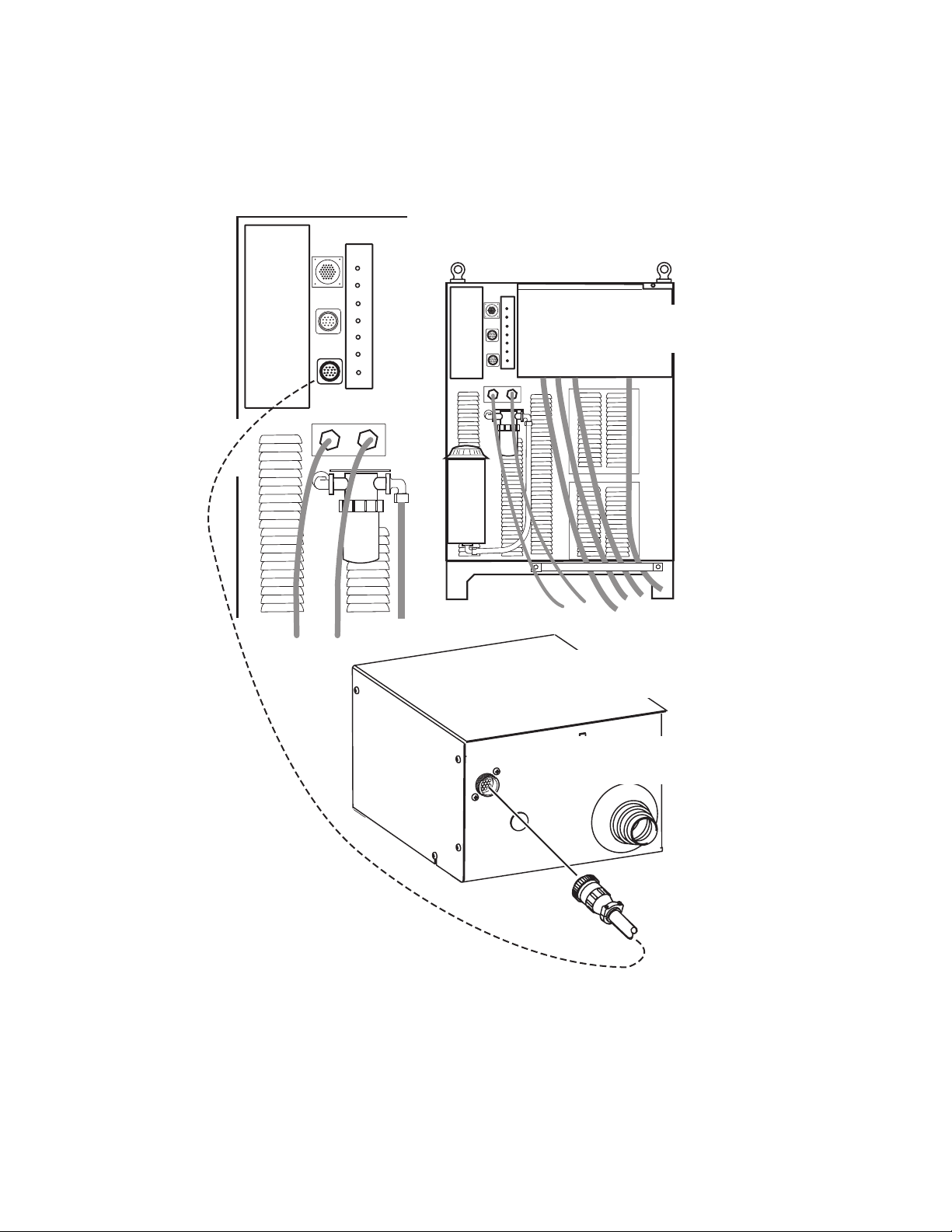
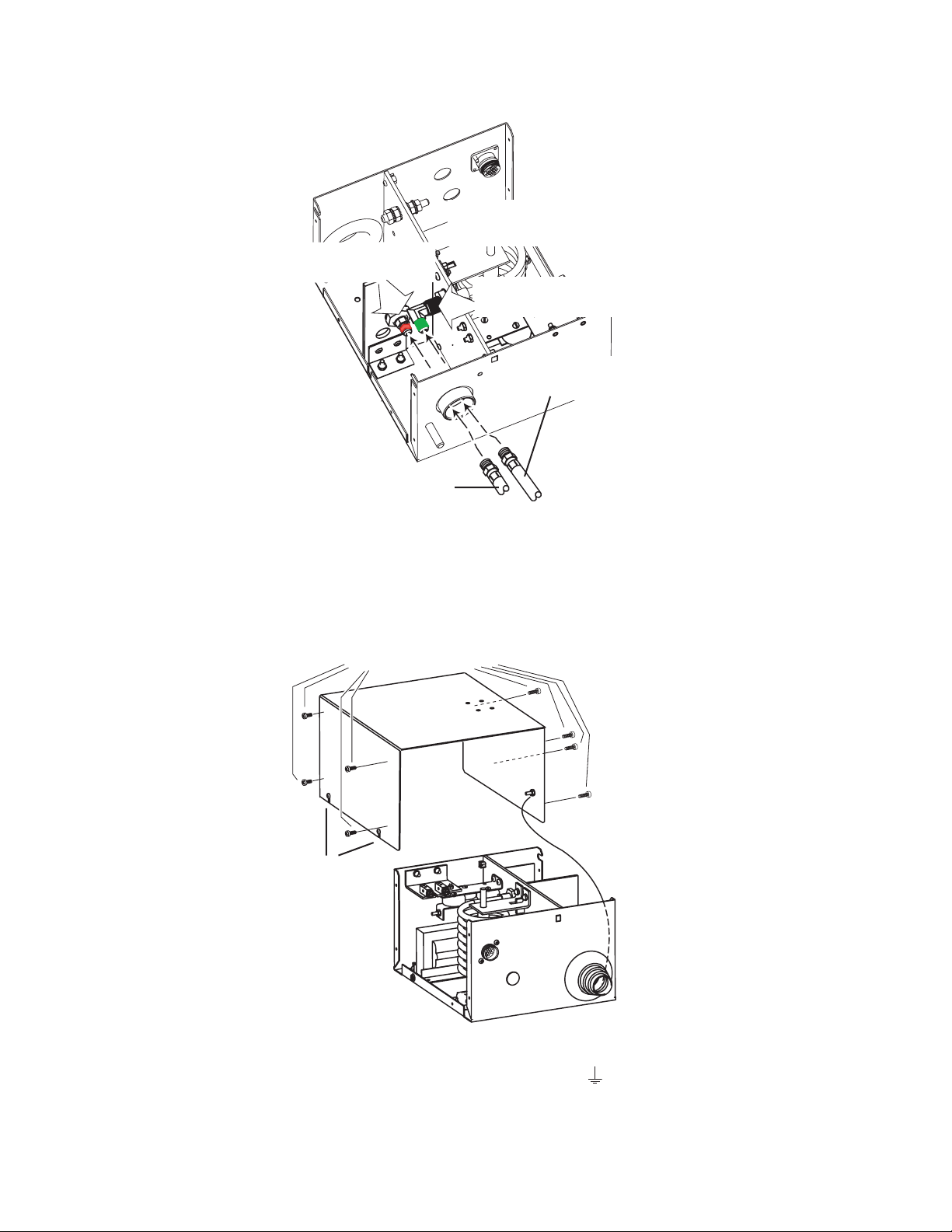
Connect Control Cable
1. Connect the Remote Arc Starter cable to the Remote Arc Starter receptacle.
Power Supply Rear Panel
RETURN
SUPPLY
COOLANT
RETURN
SUPPLY
Art # A-04801
Remote Arc Starter
Remote Arc Starter Input Connection Panel
Manual No. 0-5056 3-32 INSTALLATION
Page 55
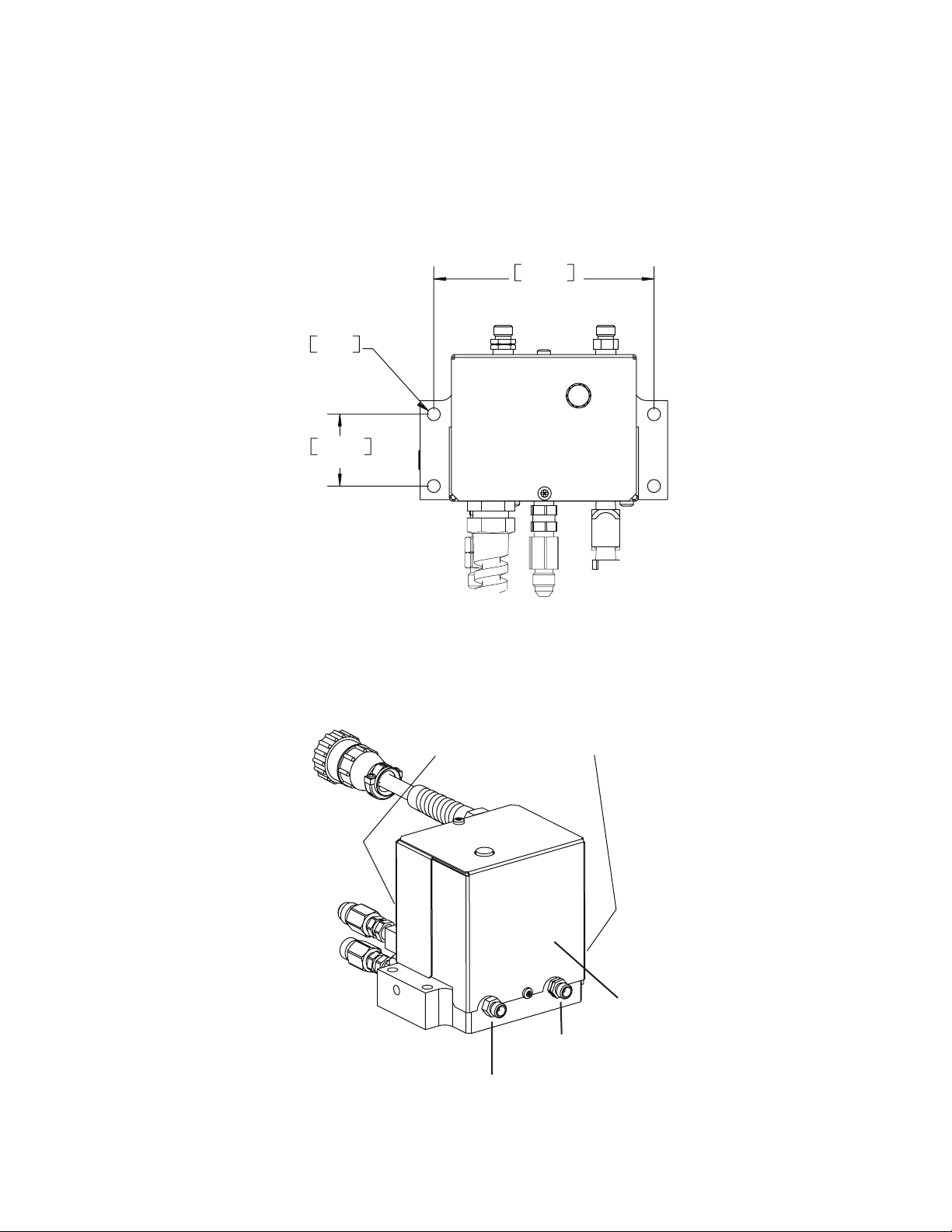
3.17 Original & XTL Torch Valve Installation
General Information
This assembly mounts as close as possible to the torch head. It accepts preflow, plasma, and shield gases from
the Gas Control Module and supplies these gases to the Torch.
Mounting
113.03 mm
4.450”
6.63 mm
.261” Dia.
36.83 mm
1.450”
Art # A-07648
1. Mount the Valve Kit as close as possible to the Torch. The valve kit can be mounted in any convenient
position, provided the outlet side (with two fittings) is closer to the torch than the inlet side (with three fittings
and a control cable connector).
2. Connect the Valve Kit outlets to the torch leads as shown. (XTL shown)
Do not remove brass plugs
Front and side
Outlet Side
Art # A-07645
Left-hand Thread:
To Torch Plasma Gas fitting
Right-hand Thread:
To Torch Shield Gas fitting
Manual No. 0-5056 3-33 INSTALLATION
Page 56
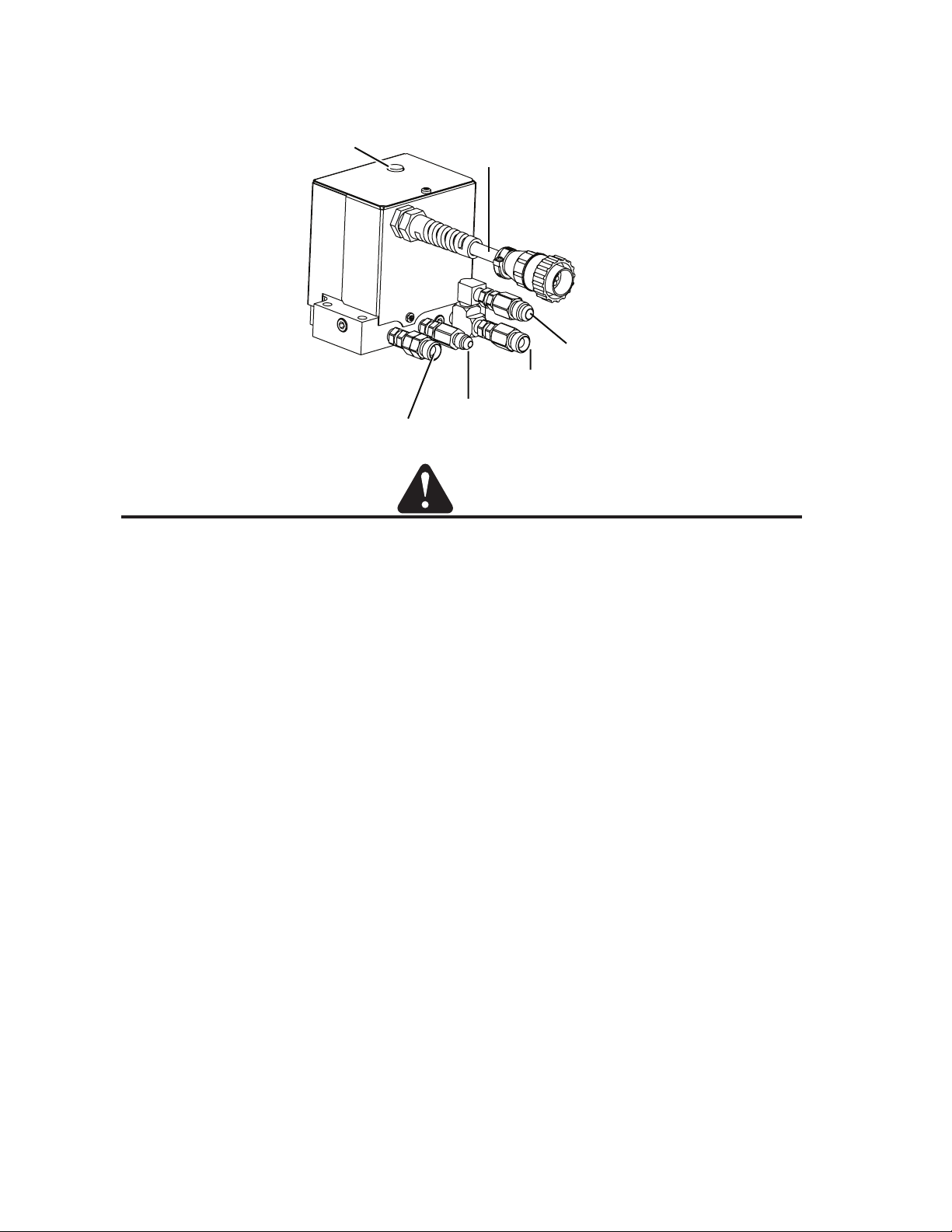
3. Connect the gas supply lines and the control cable connector from the Gas Control Module to the Valve Kit as
shown. Hold the check valves stationary while attaching the gas lines. (XTL shown)
Exhaust Muffler
Plasma Gas Inlet
Control Cable
Water Inlet
Shield Gas Inlet
Preflow Gas Inlet
Art # A-07646
CAUTION
Hold all fittings stationary while attaching hoses or leaks can be created. Side pressure can break the check valves
or weaken their connection to the torch valve assembly. All fittings must be checked for leaks after assembly.
Manual No. 0-5056 3-34 INSTALLATION
Page 57

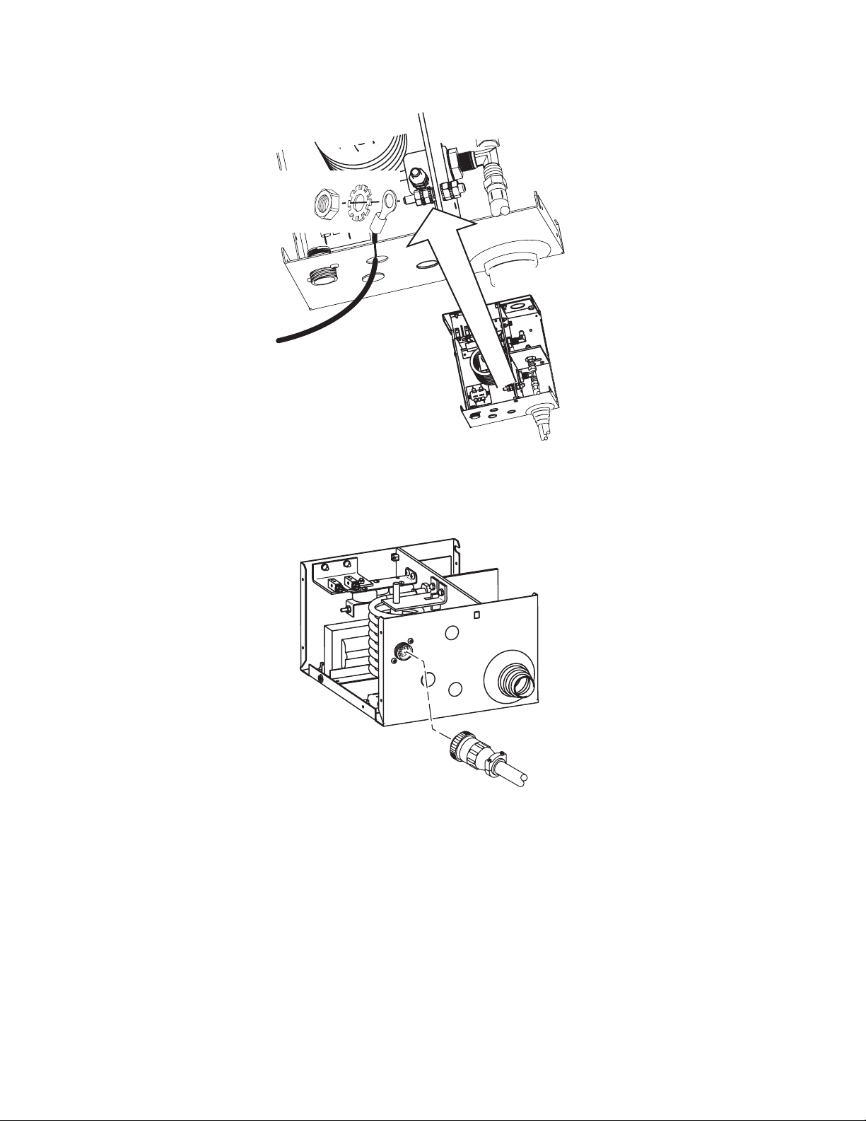
3.18 Connecting Torch
Connect the Torch as follows:
Leads Cover
Torch Leads End Cap
Groove for O-Ring
Coolant Supply,
Coolant Return,
and Pilot Leads
Shield Gas
(Right Hand Thread)
O-Ring
Mounting Tube
Torch Head Assembly
Pilot Lead
Coolant Supply
&
Power Lead (-)
Pilot Lead Connector
Plasma Gas
(Left Hand Thread)
Art # A-04746
To Torch Valve
1. Lay out the torch leads on a clean, dry working surface.
2. Hold the Torch Leads End Cap stationary. Pull approximately 18" (0.5 m) of leads through the End Cap.
3. Remove and discard the protective end caps from the Mounting Tube.
4. Install the O-ring in the groove at the upper end of the Mounting Tube.
5. Install the Mounting Tube as follows:
a. Position the Mounting Tube at the end of the leads assemblies as shown.
b. Slide the Mounting Tube upward onto the leads assemblies.
c. Press the upper end of the Mounting Tube into the lower end of the Torch Leads End Cap. Ensure that
the O-Ring on the Tube engages the mating groove inside the Torch Leads End Cap.
d. Ensure that the Mounting Tube is free to rotate within the Torch Leads End Cap.
Manual No. 0-5056 3-35 INSTALLATION
Page 58
6. Connect the gas and coolant leads to the Torch Head.
a. Coolant supply and return connections to the Torch Head are of different lengths.
b. Plasma and secondary gas connections to the Torch Head are threaded differently; the plasma gas
connection is left-hand thread, the shield gas connection is right-hand thread.
c. Hold the Torch Head leads connectors stationary; turn the leads fittings with a wrench to secure the
leads to the Torch Head. Do not overtighten.
CAUTION
The gas and coolant leads include compression fittings. Do not use sealant on these connections.
Slowly apply pressure to the gas lines. Check for leaks at all connections before continuing. If there
are no leaks, shut off the gas supplies and continue with installation.
7. Connect the pilot lead to the Torch Head. Press the two ends of the connector firmly together. Thread the
plastic lead cover/connector onto the mating Torch Head connector.
8. Press the Torch Head Assembly upward to connect to the Mounting Tube. Pull the leads back as needed
to ensure a proper fit through the Mounting Tube and Torch Leads End Cap. Hold the Torch Head Assembly
stationary; rotate the Mounting Tube to thread it onto the Torch Head.
CAUTION
Ensure that the leads do not twist within the mounting tube. Leads must lie as shown in the installation sketch.
9. The lower end of the Mounting Tube includes four threaded holes. Install an Allen set screw in any of the
threaded holes to secure the Torch Head Assembly to the Mounting Tube.
10.Install the appropriate consumable parts as shown on the following pages. The torch manual includes
diagrams showing the correct parts to install, depending on the metal to be cut and the gases in use.
Manual No. 0-5056 3-36 INSTALLATION
Page 59
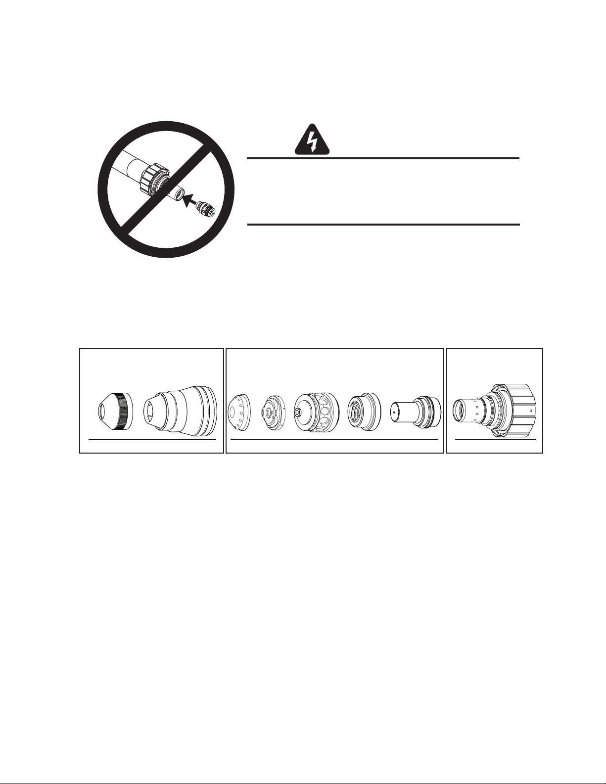
3.19 Install Consumable Torch Parts
Install the consumable parts as follows to ensure proper operation. These steps will help ensure that parts are
seated correctly.
WARNINGS
Do not install consumables into the Cartridge
while the Cartridge is attached to the Torch Head.
Keep foreign materials out of the consumables and Cartridge.
Handle all parts carefully to avoid damage,
which may affect torch performance.
Art # A-03887
1. Check the appropriate cut chart for the right combination of parts for the cutting application.
2. For 200 Amp parts only, thread the Shield Retainer onto the Shield Cup.
3. Stack the consumable parts together.
Art # A-08303
Shield
Retainer
Shield Cup
A
1 - Assemble “A” 200 A only.
Shield Cap
2 - Assemble “B”.
Shield Gas
Distributor
Tip
Plasma Gas
Distributor
Electrode
BC
3 - Assemble “B” to “C”. 4 - Assemble “A” to “B-C” assembly.
Cartridge
4. Insert the stack of consumable parts into the cartridge. Ensure that the large O-ring on the torch tip fits
completely into the cartridge. If any part of the O-ring protrudes from the cartridge, the parts are not
seated properly.
5. Use the cartridge tool to hold the cartridge assembly, while turning the shield cup (and shield retainer
for 200 Amp parts) onto the cartridge assembly. For 300 Amp parts turn the shield retainer onto the
shield cup now. When this group is fully assembled, the shield should protrude from the front of the
shield cup or shield retainer. Without this protrusion the shield cup is not properly tightened onto the
cartridge assembly.
6. Take the cartridge tool off the cartridge. Fit the cartridge assembly onto the torch head. The Speed Lok
ring should clidk into place and the cartridge assembly should touch the large O-ring on the torch body.
Manual No. 0-5056 3-37 INSTALLATION
Page 60

Torch Head
0.063 - 0.083"
(1.6 - 2.1 mm)
Protrusion
Installing Assembled Cartridge Onto Torch Head
6. Slide the ohmic clip over the shield cup if using ohmic torch height sensing.
Torch Head O-Ring
Art # A-08300_AB
Manual No. 0-5056 3-38 INSTALLATION
Page 61

55 - 100 Amp Parts Assembly
Electrode
Plasma Gas
Distributor
Tip
Shield Gas
Distributor
Shield Cap
3: Thread Shield Cup onto Cartridge
1: Stack Parts
O-Ring
on Tip
2: Press Cartridge onto Stacked Parts
No Gaps
Between Parts
Cartridge Covers
O-Ring
on Torch Tip
4: Check Shield Cap Protrusion
Shield Cup
Shield Cap Protrudes
0.063-0.083" (1.6 - 2.1 mm)
Installing Assembled Cartridge Onto Torch Head
Shield Cap
Art # A-04873
Manual No. 0-5056 3-39 INSTALLATION
Page 62

7. Connect the wire lead from the height finder to the ohmic clip if using ohmic torch height
Ohmic Clip
sensing.
A-03393
NOTE
Ohmic height sensing is not recommended with water shield. Water on the plate interferes electrically with the
ohmic sensing circuit.
Manual No. 0-5056 3-40 INSTALLATION
Page 63

3.20 Complete the Installation
1. Remove the cap from the coolant tank. Fill the coolant tank to the level shown, with Thermal Dynamics
coolant. The coolant level is visible through the translucent coolant tank. The amount of coolant required
varies with torch leads length.
Coolant Capabilit i es
Cat. Number and Mixture Mixture Protects To
7-3580 'Extra-Cool
7-3581 'Ultra-Cool
7-3582 'Ext reme Cool
* For mixing wit h D-I Cool
TM
'
TM
'
TM
' Concent rate* -65° F / -51° C
TM
7-3583
25 / 75 10° F / -12° C
50 / 50 27° F / -33° C
COOLANT
RETURN
SUPPLY
RETURN
SUPPLY
Fill Range
Coolant Tank
Art # A-04803
2. After the complete system has been installed, check that the coolant has been pumped through the
system as follows (see NOTE):
Manual No. 0-5056 3-41 INSTALLATION
Page 64

NOTE
Depending on the length of the torch leads, the system may require more coolant after turning the
system ON for the first time.
a. Place the ON/OFF Switch to ON.
b. After about 30 seconds the system may shut down if the leads are not full of coolant.
c. Place the ON/OFF switch to OFF.
d. After 10 seconds place the ON/OFF switch to ON again.
e. Repeat steps ‘b’ through ‘d’ until the system no longer shuts down. Depending on the length of the torch
leads this sequence may need to be done three to five times.
f. After the system stays operational allow the pump to operate for ten minutes to properly purge any air
from the coolant lines before using the system.
3. Re-fill the reservoir and re-install the filler cap.
4. Purge coolant from the torch before firing the torch. Ensure there are no leaks before use. If leaks are
evident, consult the coolant leak trouble-shooting guide in the maintenance section of this manual.
Page 65

SECTION 4: OPERATION
4.01 Power Supply Control Panel
AC Indicator
Temp Indicator
Art # A-04862
AC Power Indicator
Indicates AC power is being supplied to the system when the ON/OFF switch is in ON position. When switch
is first set to ON, the indicator will blink, indicating gas purge at power on.
TEMP Indicator: Normally OFF. Indicator will come ON when the internal temperature sensors detect
temperatures above normal limits. Let the unit cool before continuing operation.
Gas Indicator
DC Indicator
Status Indicator
GAS Indicator: Normally ON. Indicates adequate gas pressure for operation in the system.
DC Indicator: Indicates the power supply is generating output DC voltage.
Status Indicator: Show system status. The number of flashes indicates the status. Refer to the Status
Code Section for details. On power supply start-up, the indicator flashes to show the revision level of the
operating software installed in the system.
Manual No. 0-5056 4-1 OPERATION
Page 66
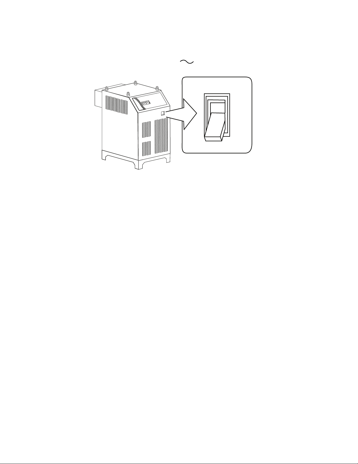
4.02 Start-Up Sequence
1. Connect system to primary input power.
2. Turn ON/OFF switch to ON (up) position. AC Indicator turns ON.
POWER
I
OFF
O
O
Art # A-04812
3. Check the AC indicator. If indicator does not light, reverse two phases of primary input power cable. If indicator
is ON, system is ready to operate (pending fault checks by internal circuitry).
ON
OFF
Manual No. 0-5056 4-2 OPERATION
Page 67
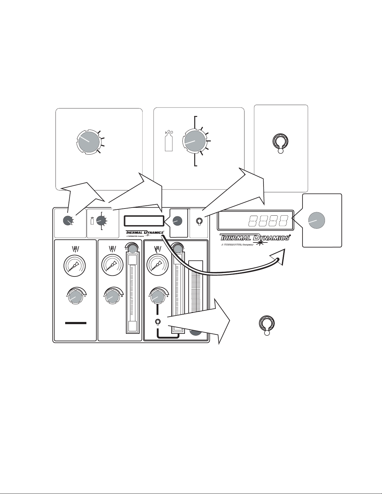
4.03 Gas Control Module Operation
Functional Overview
The Gas Control Module provides all Plasma and Secondary gas selection and control instrumentation. There are
various controls and indicators used to set gas pressures and flows.
O2 - AIR
MODE
MODE
RUN
SET PREFLOW
SET PLASMA
& SHIELD
TEST
PREFLOW
GAS
RUN
SET PREFLOW
SET PLASMA
& SHIELD
TEST
O2 - AIR
O2 - O2
H35 - N2
F5 - N2
AIR - AIR
N2 - H20
N2 - N2
PLASMA
O2 - O2
H35 - N2
F5 - N2
AIR - AIR
N2 - H20
N2 - N2
GAS
ENABLE
DISABLE
H20
MIST
PLASMA
POWER
SUPPLY
AMPERAGE
SET-UP
9
SHIELD
9
ENABLE
DISABLE
PLASMA
POWER SUPPLY
AMPERAGE
SET-UP
PRESSURE
GAS
FLOW
GCM
2010
PRESSURE
GAS
FLOW
Art # A-04771
Manual No. 0-5056 4-3 OPERATION
Page 68
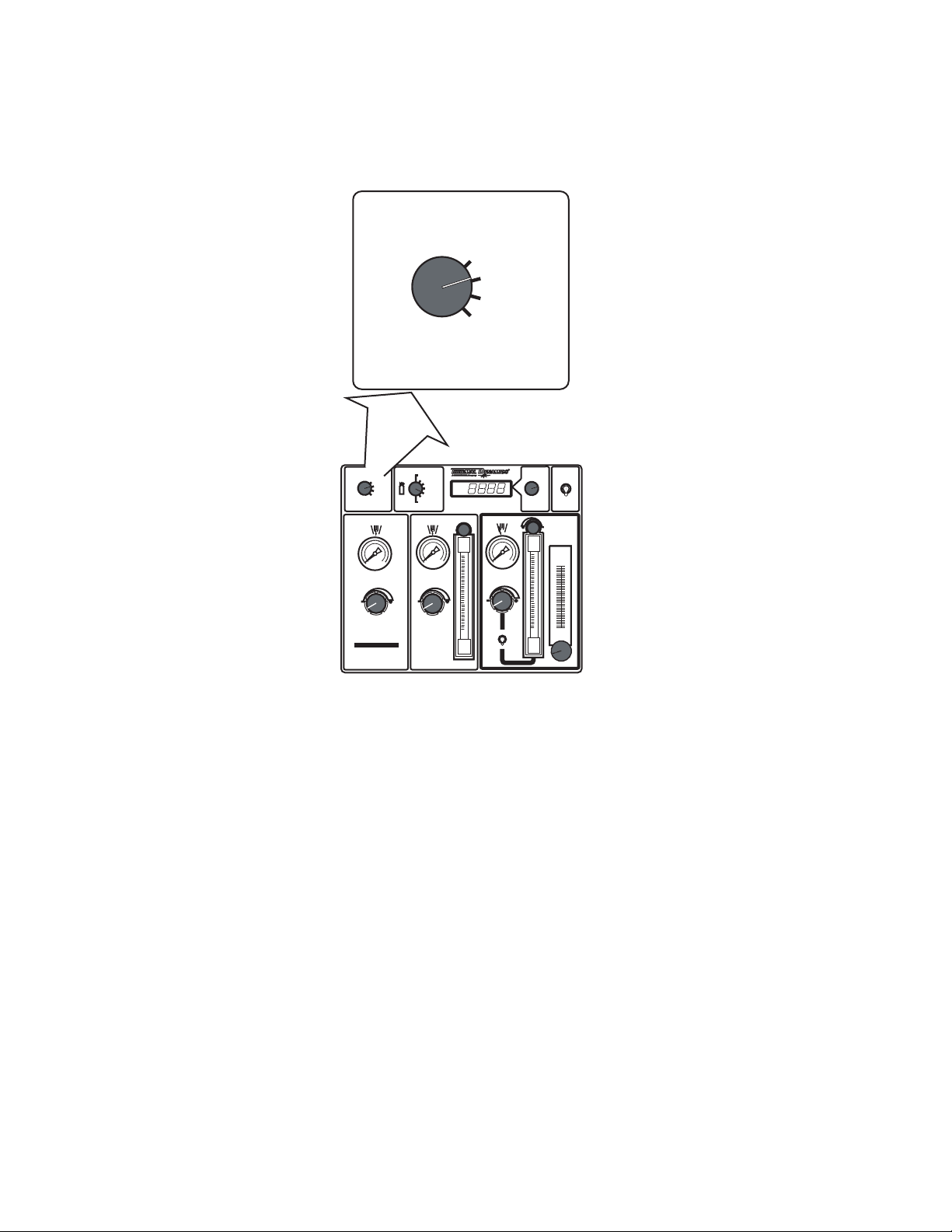
Gas Control Module: Controls & Indicators
1. MODE Selection Switch
MODE
O2 - AIR
SET PREFLOW
SET PLASMA
& SHIELD
O2 - O2
2 - H2O
N
2 - N2
N
GAS
PLASMA
RUN
TEST
MODE
PREFLOW
H35 -N
F5 - N2
AIR - AIR
2
Plasma Cutting System
RUN
SET PREFLOW
SET PLASMA
& SHIELD
TEST
High Precision
SHIELD
9
AMPERAGE
SET-UP
9
ENABLE
DISABLE
PLASMA
POWER SUPPLY
H
2
O
MIST
GCM
2010
GAS
PRESSURE
FLOW
Art # A-04765
• Normally in the RUN position during torch operation.
• In the SET PREFLOW position, Air or N2 travels to the torch. The Preflow valve remains open for 2 minutes
to allow the operator to adjust flow pressure.
• In the SET PLASMA & SHIELD position, gases travel to the torch. The Preflow valve at the torch remains open
for 2 minutes to allow the operator to adjust flow pressures and rates.
• In the TEST position, gases fill the torch leads. The display shows the pressure of the plasma gas while
flowing. After 1 minute the Module shuts off the valves at the torch.
Manual No. 0-5056 4-4 OPERATION
Page 69
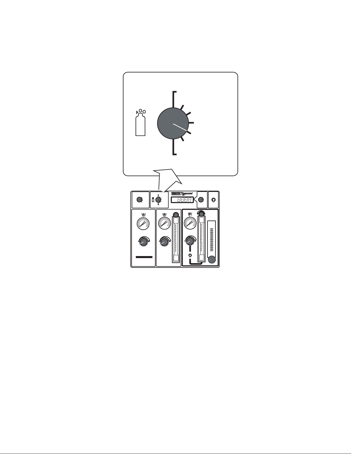
2. GAS Selection Switch
Selects combinations of plasma and shield gases.
O2 - AIR
O2 - O2
GAS
RUN
SET PREFLOW
SET PLASMA
& SHIELD
TEST
MODE
PREFLOW
GCM
2010
H35 -N
2
F5 - N2
AIR - AIR
N
2 - H2O
2 - N2
N
O2 - AIR
O2 - O2
2
H35 -N
F5 - N2
AIR - AIR
N
2 - H2O
N
2 - N2
PLASMA
High Precision
Plasma Cutting System
9
GAS
SHIELD
PRESSURE
FLOW
GAS
Art # A-04766
AMPERAGE
SET-UP
9
ENABLE
DISABLE
PLASMA
POWER SUPPLY
H
2
O
MIST
Manual No. 0-5056 4-5 OPERATION
Page 70
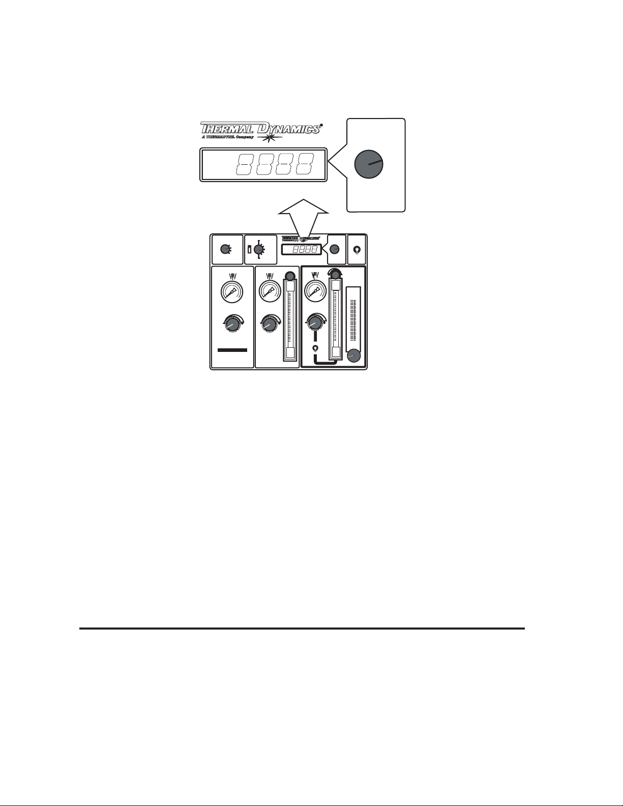
3. Amperage / Set-Up Knob
Adjusts the output amperage of the torch.
High Precision
Plasma Cutting System
O2 - AIR
SET PREFLOW
SET PLASMA
& SHIELD
O2 - O2
H35 -N
2
F5 - N
2
AIR - AIR
N
2 - H2
O
N
2 - N2
PLASMA
High Precision
Plasma Cutting System
9
GAS
MODE
RUN
TEST
PREFLOW
GCM
2010
GAS
SHIELD
PRESSURE
FLOW
AMPERAGE
SET-UP
9
AMPERAGE
SET-UP
ENABLE
DISABLE
PLASMA
POWER SUPPLY
2
O
H
MIST
Art # A-04767
4. Plasma Power Supply Enable / Disable Switch
In the DISABLE position, stops the system from starting a pilot arc at the torch, while the operator selects and
adjusts gases, or changes torch parts. The DISABLE position also stops coolant and gas flow. In the ENABLE
position, allows normal operation (under control of the CNC device).
5. PREFLOW Control Knob and Pressure Gauge
Used to set preflow gas pressure. MODE switch must be in PREFLOW position.
6. PLASMA and SHIELD Control Knobs, Pressure Gauges, and Flow Meters
Used to set plasma and shield gas pressures and flows. MODE switch must be in SET PLASMA & SHIELD
position.
7. H2O Mist Control Knob and Flow Meter
Used to set water flow rate. MODE switch must be in SET PLASMA & SHIELD position. GAS selection
switch must be in N2-H2O position.
NOTE
Water mist is not used in all applications.
Manual No. 0-5056 4-6 OPERATION
Page 71

4.04 Sequence Of Operation
1. Set the Plasma Power Supply Enable / Disable switch to Disable.
DANGER
Alway shut off input power to the system before changing or inspecting torch parts.
a. Change the torch parts if necessary.
b. Set the Plasma Power Supply Enable / Disable switch (on the Gas Control Module) to Enable. The
Module performs purges of 15 seconds, 11 seconds, and another 11 seconds. This removes water from
the torch parts.
2. Select the desired plasma and shield gas by setting the Gas Selection switch to the desired position. 2
seconds after gas selection, the module purges the new gas(es) through the leads.
3. Set the preflow gas pressure.
a. Set the MODE switch to SET PREFLOW.
b. Use the PREFLOW control knob to set preflow gas pressure. Refer to the torch manual for pressure
settings.
c . Use the AMPERAGE SET-UP control knob to set the desired pre-charge pressure set point.
Press the control knob for 2 seconds without rotating. Then rotate the knob to adjust pressure.
4. Set the plasma and shield gas pressures and flows.
a. Set the MODE switch to SET PLASMA & SHIELD.
b. Use the PLASMA and SHIELD control knobs, pressure gauges, and flow meters to set plasma and
shield gas pressures and flows. Refer to the torch manual for pressure settings.
c . In installations using water shield, use the H2O MIST control knob and flow meter to set water flow rate.
Refer to the torch manual for flow rates.
5. Use the AMPERAGE SET-UP control knob to set the desired amperage output. The module will update
the amperage every 2 seconds after the last adjustment to the knob. The module keeps the set point in
memory.
6. Place the MODE switch to the RUN position.
7. Set the Plasma Power Supply Enable / Disable sswitch (on the Gas Control Module) to Enable. The
Module performs purges of 15 seconds, 11 seconds, and another 11 seconds. This removes water from the
torch parts.
NOTE
When switching gases between operations, allow enough purge time to clear the prior gas from the torch leads.
CAUTION
While nothing prevents the operator from switching gases during piloting or cutting it is not recommended to do
so. If the operator switches gases during piloting or cutting, the power supply will finish the cut with the first gas
chosen. Then the gas control will switch to the new gas. Switching gases during piloting or cutting may damage
torch parts, torch leads, the control module, or the piece being cut.
Manual No. 0-5056 4-7 OPERATION
Page 72

Cut Quality
Cut quality requirements differ depending on application. For instance, nitride build-up and bevel angle may be
major factors when the surface will be welded after cutting. Dross-free cutting is important when finish cut quality
is desired to avoid a secondary cleaning operation. Cut quality will vary on different materials and thicknesses.
Kerf Width
Cut Surface
Left Side
Cut Angle
Right Side
Cut Angle
A-00512
Top
Spatter
Build-Up
Dross
Cut Surface
Drag Lines
Bevel Angle
Top Edge
Rounding
A-00007
Cut Surface
The condition (smooth or rough) of the face of the cut.
Bevel Angle
The angle between the surface of the cut edge and a plane perpendicular to the surface of the plate. A perfectly
perpendicular cut would result in a 0° bevel angle.
Top-Edge Rounding
Rounding on the top edge of a cut due to wearing from the initial contact of the plasma arc on the workpiece.
Dross Build-up and Top Spatter
Dross is molten material which is not blown out of the cut area and re-solidifies on the plate. Top spatter is
dross which accumulates on the top surface of the workpiece. Excessive dross may require secondary cleanup operations after cutting.
Kerf Width
The width of material removed during the cut.
Nitride Build-up
Nitride deposits which may remain on the cut edge of the carbon steel when nitrogen is present in the plasma
gas stream. Nitride buildups may create difficulties if the steel is welded after the cutting process.
Marking
Marking requires adjusting the pre-charge pressures. Refer to the torch data section for details.
Manual No. 0-5056 4-8 OPERATION
Page 73

Direction of Cut
The plasma gas stream swirls as it leaves the torch to maintain a smooth column of gas. This swirl effect results
in one side of a cut being more square than the other. Viewed along the direction of travel, the right side of the
cut is more square than the left.
Left Side
Cut Angle
Right Side
Cut Angle
A-00512
Clockwise
Scrap
Counter-
Clockwise
Scrap
Workpiece
Art # A-04182
Swirl Effect on Side Characteristics Of Cut
To make a square - edged cut along an inside diameter of a circle, the torch should move counterclockwise
around the circle. To keep the square edge along an outside diameter cut, the torch should travel in a clockwise
direction.
Underwater Cutting
Cutting on a water table either underwater or with the water touching the plate or with a water muffler system
is not recommended. If a water table is used the water level must be a minimum of 4 inches from the bottom of
the plate. Failure to follow this recommendation could result in poor cut quality and short consumable parts
life.
Ohmic Sensing
Ohmic sensing is not recommended with water shield. Water on the plate interferes electrically with the ohmic
sensing circuit.
4.05 Gas Selection
A. Plasma Gases
1. Air Plasma
• Most often used on ferrous or carbon base materials for good quality at faster cutting speeds.
• Air plasma is normally used with air shield.
• Only clean, dry air is recommended for use as plasma gas. Any oil or moisture in the air supply will substantially reduce torch parts life.
• Provides satisfactory results on nonferrous materials.
2. Argon/Hydrogen (H35) Plasma
• Recommended for use on 3/4 in (19 mm) and thicker stainless steel. Recommended for 1/2 inch (12 mm) and
thicker nonferrous materials. Ar/H2 is not normally used for thinner nonferrous materials because less
expensive gases can achieve similar cut quality.
• Poor cut quality on ferrous materials.
• Provides faster cutting speeds and high cut quality on thicker materials to offset the higher cost.
• A 65% argon / 35% hydrogen mixture should be used.
Manual No. 0-5056 4-9 OPERATION
Page 74

3. Oxygen (O2) Plasma
• Oxygen is recommended for cutting ferrous materials.
• Provides faster cutting speeds.
• Provides very smooth finishes and minimizes nitride build-up on cut surface (nitride build-up can cause
difficulties in producing high quality welds if not removed).
4. Nitrogen (N2) Plasma
• Provides better cut quality on nonferrous materials such as stainless steel and aluminum.
• Can be used in place of air plasma with air shield or carbon dioxide (CO2).
• Provides much better parts life than air.
• A good clean welding grade nitrogen should be used.
B. Shield Gases
1. Compressed Air Shield
• Air shield is normally used when operating with air plasma.
• Improves cut quality on some ferrous materials.
• Inexpensive - reduces operating costs.
2. Nitrogen (N2) Shield
• Nitrogen shield is used with Ar/H2 (H35) plasma.
• Provides smooth finishes on nonferrous materials.
• May reduce smoke when used with Ar/H2 plasma.
3. Water Shield
• Normally used with nitrogen, Ar/H2, or air plasma.
• Provides very smooth cut surface.
• Reduces smoke and heat input to the workpiece.
• Effective up to 1/2 inch (12.7 mm) maximum material thickness.
• Tap water provides low operating expense.
4.06 Power Supply Status Codes
On start-up and during operation, the power supply control circuitry performs various tests. If the circuitry
detects a condition requiring operator attention, the status indicator on the control panel flashes a 2-part code
to indicate a code group and then a particular condition within the group. After 4 seconds, the sequence
repeats.
Example: Indicator flashes 4 times; the condition is in group 4. After a 1.2 second delay, the indicator blinks
3 times; the condition code is 4-3, indicating that the coolant is overheating. After a 4-second delay, the
indicator repeats the sequence until the condition is corrected.
Some conditions can be active indefinitely, while others are momentary. The power supply latches momentary
conditions; some momentary conditions can shut down the system. The indicator may show multiple conditions in sequence; it is important to recognize all possible conditions that may be displayed.
Note
These codes are for systems with Firmware versions 2.4 or later. If your system’s Firmware is a prior version,
contact your distributor for updates.
Manual No. 0-5056 4-10 OPERATION
Page 75

Status Code Key
Status
Code
1 -1 System not Enabl e d or Missi ng
AC Input Phase
1-2 Pilot Ig nition Failure
1-3 Lost P il ot Pil ot went out without shutoff si g nal; Preflow pressure
1 -4 Loss of T ransfer Arc transfer (>50 ms.) then arc l ost with STAR T sti ll on.
1-5 Of the Plate Function not currently enabled.
1-6 Pilot Timed out w / o Transf e r Must tra nsfer from Pil ot t o Cutting Arc in 8 5 ms. (SW8- 1
1-7 Tip Saver Func t ion not currently enabled.
1-8 Possible S horted Torch Detected ti p voltage too close to electrode voltage.
2-1 M issing Phase B lown fuse, Broken or loose connec t ion on power cabl e
2-2 Wrong in put voltage
2-3 Inver t e r or Pilot R egulato r Ove r
Temperature
2-4 Power S upply not Ready Defective i nverter
2 -5 DC Output Low Output less than 60 VDC ; Defective inverter, shorte d
2-6 Primary over current or
imbalance fault
2-7 Unexpect e d current Current >20A in work or pilot l eads before pil ot ignition;
2-8 Unexpect e d current in pilot
circuit
2-9 Unexpected current in work
lead
Mes sage Caus e/Remedy
Plasma Enabl e Off ; External E -Stop Acti vated or CCM
TB1-1&2 jum per missing; Missing AC Phase; No powe r
Pilot did not start within 1 5 seconds.
Preflow pressure too high; Defecti ve Arc S tar ter
Standoff too high; C urren t set t oo low.
OFF) or 3 sec. (S W8-1 ON). Standof f too high or void in
wo rk under torch ; c ut c urrent t oo low for consumables;
Preflow pressure too low.
Plasma flow/pressure too low; Plasma leak; cut current
too high; shorted torch body; co nsumable parts worn
out.
Inverter(s) not configured correctly for input voltage;
Poo r power quality (brownouts, dr opo ut s);
Inpu t po wer capac ity / wiring too small ca u sing vol ta ge
drop ; broke n o r lo ose power c able con ne ctions.
Fa il ed fan; Ambient above 40 deg C. ( 104 F); Blocked
airflow
output; Shorted pil o t regulator (chopper) ; CCM voltage
sense (J6) wire open or disco nnected.
Ov e r cur rent dete cted in in verter prim ar y circuit, remove
pow er to reset; defective i nvert e r; voltage surge;
Possible shorted torch; Defective cur rent sensor.
Current > 5A in pilot circuit; w rong or mismatche d
consumables; P ilot lead shorted to negative i n t orch tube;
Possible shorted torch
C urrent > 5A in work lead; Shor t to c hassis in R AS;
Nega tive le a d short to gnd.
Manual No. 0-5056 4-11 OPERATION
Page 76

p
y
N
Status Code Key (cond)
Status
Code
3-1 Gas Control Communication
fa u lt, Cannot establish
Communication with gas
control.
3-2 Gas Control Communication
reply fault, c onn e ction was
established but CCM did
recei ve a r epl y to a process
request.
3 -3 Gas Pressure Low
3-4 Ga s Control not ready Purging; not in R UN mode; Ga s Control fa u lty, repl ace PCB .
3-5 Gas Control Protocol Fault Application error or firmware compatibility fault
Message Cause/Remedy
I f GCM 1000: Contr o l cable not connected or Basi c ID signal o pe n .
GC M 2 01 0 & 2000: Dirt on fibe r ends or in connec to rs, blow out with clean
dr y air; fiber not lo c ked into connect or; sharp be n ds in fiber ; fi be r
defective; Gas Control P CB defective, replace. CCM defective, replace.
Gas Control did not re p ly to si gn a l from CCM i n allowed time. Dirt on fiber
ends or in conne ctor s, blow out with clean dr y air; fiber not locked into
connector; sharp bends in fiber; fiber defective. If problem persists Gas
Control PCB li k ely defective, replace board.
If GC M 1000, Plasma < 15 PSI; fa u lty or disconnect e d pressure SW.
If GC M2010_ AG, GCM2000_AC or later or Gas Control has been upda t ed
w ith 19X22 19_ AG or lat er PCB : Plasma or Shie ld input out of range 105-135
3-6 Invalid Current Control level
from G CM
3-7 Gas Control returns wrong
command sequence
3-8 CCM and Gas Control type
(Autocut-Ultracut) mismatch
3-9 Gas Control Communication
reply fault
3 -10 War n ing. -- Gas Control S yste m will function but control may not be opt imized for best
4-1 Coolant Level low fault Check coolant lev e l, a d d as needed.
4-2
Low coolant flow after power
on purge.
ot cutting: < 0.7 gal/min for 15
sec;
C utting: flow between 0.35 to
0.7 gal/min for 3 sec. or
4-3
Coolant overheated
deg. C, 158 deg F)
4-4
Coolant System not ready
D uring power on purge /
priming, flow did not rea c h 0.35
gal/min for at least 5 seconds
(>70
GC M sent output c urre nt level outside t h e range of the powe r supply,
Check firmware com
Check firmware compatibility
Install correct CCM or Gas Control for system
Reply no t compatible wit h request; Check firmwa re compatibili t y
Suction leak introducing air i nto coolant, suspect rear panel f ilter seal;
clogged filter; defe ctive p ump.
Coolant fan fa iled; radiator fins clogged w ith dirt; Ambient temper atur e >
4 0 deg C .
. If new installation recycle power to restar t pump, may take a few times to
fill hoses;
D amaged torch coolant tube; Suction leak intr odu c ing air into coolant,
suspect rear panel filter seal; clog ge d filter; defective pump.
atibilit
4-5 Low Coolant Level - Warning
While cut t ing detec t ed low coolant le ve l, does not stop cut.
Add coolant as r equired.
Manual No. 0-5056 4-12 OPERATION
Page 77

Status Code Key (cond)
p
Status
Cod e
5-1 CANBUS Failure to
Acknowledge f ault.
CANBUS Off due to
5-2 D irt on fiber ends or in connec t o rs, blow ou t wit h c lean dry ai r; fiber not
excessive data errors;
5-3 D irt on fiber ends or in connec t o rs, blow ou t wit h c lean dry ai r; fiber not
CA NBUS data error warning
Errors increasing, will soon
fault.
5-4 CCM Message not sent Dirt on fiber ends or in connec t o rs, blow out with c lean dry air ; fi ber not
6-1 CCM Analog Voltage Error Replace CCM
6-2 CCM ADC or DAC error Replace CCM
6-3
Coolant Flow too High error
flow > 2 .7 ga l/min
6-4 CCM Data Memory error Replace CCM
Message Cause/Remedy
I f GCM 1000, Ba sic ID signa l missi ng ; Other gas controls, Fiber
disconnec t ed or broken, Transceiver ( what fiber plugs into) fault, replace
Gas control PCB or CCM
locked into connector; shar
.
locked into connector; sharp bends in fiber; fiber defective;
locked into connector; sharp bends in fiber; fiber defective; CANBUS
hardware error (CCM or Gas Control PCB)
Torch coolant tube broken o r missing;
,
CCM fault, replace CCM
bends in fiber; fiber defective;
Manual No. 0-5056 4-13 OPERATION
Page 78

4.07 Remote Arc Starter: Service Chart
e
S
g
Arc Starter S e r vice Char t
Symptom Cause Check Remedy
Use conduct ivit y meter
Use capacit an c e met er Reconnec t or replac e.
Capacitance mete r Replace.
V isual inspect ion Reconn ec t .
V isual inspect ion Reconn ec t .
Visual inspection Replac e coolant line(s).
Visual Inspection of color -coded
connections
Loosen fit ting slight ly and chec k
for coolant flow
Visual inspection o f lead
attachment to Arc Starter
Visual inspection o f ground wire
to Arc Starter
Visual inspection / capacitor
me asurement
No Pilot ignition:
Spark in Arc Starter
but no ignition
No Pilot ignition:
No Spark
in Arc Starter
No cooling or
insufficient cooling:
Leaks coolant
No cooling or
insufficient cooling:
No Coolant Flow
Erratic System
Behavior
(EMI Interference)
Coolant ha s become conduc tiv
Pilot return wire not connected Visual inspection Connect Wire.
Spar k gap set too close Check with feeler gaug e Set to 0.063" ±0.002"
High Frequency cap (C4)
possibly open
Broken or missing fe r r ites Visual inspect io n Replac e.
Shor t across in inductor (L1) Visual inspection
Spar k gap bus caps
(C1, C2, C3)
broke n or defect ive
Negativ e supply not
connec t ed c or r ec t ly
Spar k gap set too large Check wi th feeler gaug e Set to 0.063" ±0. 002"
Faulty transformer Resistanc e measurement Replace.
No 120V supply Check i nput vol tage at EMI filter
No/ loo se connect i on
to spark gap
Faulty E MI filter Voltage/ Resistor measurement Rep lac e.
Loose fit t in g(s) V isual inspect ion T ighten fittings.
Failu r e to braze joints (L1) Visual inspectio n Replac e HF Coil.
Damaged or punctured
coolant lin e( s).
Supply & return hose rev ersed
Blockage in coil or
supply/return hoses
hield Drain / Torch lead inner
shield connector
missin
Missing or loose
ground c onne c tion
Cap C5 not connected,
open or loose
or loose.
Flush syst em,
replac e coo lant.
Remov e short;
incre ase coil gap s.
M ake connections;
replac e har ness.
Match co olan t connect ion colors
to arc starter fitting colors.
Flush syst em.
Reconnec t / t ighten
lead connec t o r s.
Make or t ighten
connec tions to
good ground.
Replace P CB.
Manual No. 0-5056 4-14 OPERATION
Page 79

4.08 Remote Arc Starter: Spark Gap Adjustment
0.063" ± 0.002"
1.6 ± 0.05 mm
Art # A-04857
Manual No. 0-5056 4-15 OPERATION
Page 80

This page intentionally blank
Manual No. 0-5056 4-16 OPERATION
Page 81
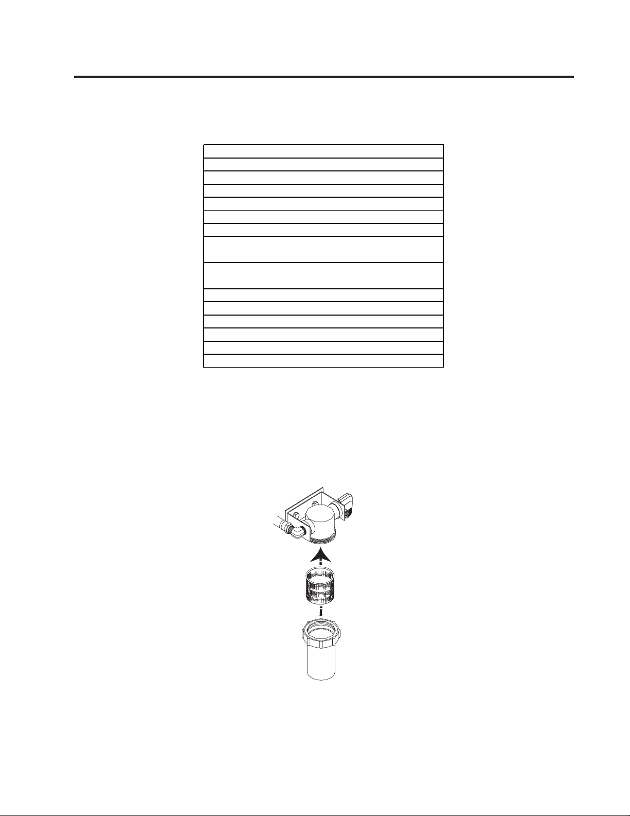
SECTION 5: MAINTENANCE
5.01 Periodic Checks
Perform the following checks periodically to ensure proper system performance.
Pow e r S upply Ma i nte na nce S che dule
Daily
Check c ool ant level; add coolant as needed.
Check gas hos e connections and pressures.
M onthly
Check c ool ing fan and radiator; clean as needed.
Check gas hos es for cracks , l eak s, or abrasi on.
Replace as needed.
Check all electri cal c onnec t i ons
for crack s or abrasion. Replac e as needed.
Six M onths
Clean or replace ext ernal coolant fil t er.
Clean coolant t ank .
Vac uum out any dus t bui l dup ins i de power supply.
Check int ernal coolant filt er
5.02External Coolant Filter Cleaning Procedure
Periodic cleaning of the coolant filter ensures maximum coolant flow efficiency. Poor coolant flow causes inefficient torch parts cooling with consequent faster consumable wear.
Clean the coolant filter as follows:
1. Disconnect the system from main input power.
Filter Screen
Filter Holder
Art # A-04811
2. Unscrew and remove the filter bowl by hand. Be sure to keep the O-ring.
3. Remove and clean the filter. Re-install the bowl, tightening it by hand. Be sure the O-ring is in place.
4. Turn the system on and check for leaks.
Manual No. 0-5056 5-1 MAINTENANCE
Page 82

5.03 Internal Coolant Filter Cleaning Procedure
The in-line filter screen should be cleaned periodically. To gain access to the In-Line Filter Assembly remove the
right side panel (viewed from the front of unit) of the Power Supply. Remove the filter screen by unscrewing the
filter holder from the In-Line Filter Assembly. Clean the filter screen by rinsing with hot soapy water. Remove soap
residue by rinsing with clean hot water. Be sure that all the soap has been removed and the screen is dry of water
before re-installing in the In-Line Filter Assembly.
5.04 Coolant Replacement Procedure
Replace coolant as follows:
1. Disconnect the system from main input power. At the bottom of the coolant tank, disconnect the coolant
line fitting and collect coolant in a disposable container.
2. Connect the system to main input power and turn it on to allow the pump to empty the tank. The pump will
run approximately for 20 seconds before the flow switch causes an interlock. This procedure may be
repeated a few times until the tank is completely empty.
3. Connect the coolant line fitting and fill the tank with fresh coolant until the right level is reached.
COOLANT
RETURN
Fill Range
Coolant Tank
SUPPLY
RETURN
SUPPLY
Art # A-04803
4. Turn system on, let it run for a few minutes and check coolant level, refill if necessary.
Manual No. 0-5056 5-2 MAINTENANCE
Page 83

SECTION 6: REPLACEMENT ASSEMBLIES & PARTS
6.01 Main Component / System Replacement
Complete Unit / Component Catalog Number
Ultra-Cut® 200 Power Supply, 208/230V 3-9119-1
Ultra-Cut® 200 Power Supply, 460V 3-9119-2
Ultra-Cut® 200 Power Supply, 400V 3-9119-3
Ultra-Cut® 200 Power Supply, 400V, (CE) 3-9119-4
Gas Control Module (GCM-2010) with Torch Valve Assembly 3-9131
Gas Control Module (GCM-2010) Only 7-4000
Original Torch Valve Assembly Only 4-3049
XTL Torch Valve Assembly Only 4-3054
Remote Arc Starter (RAS-1000) 3-9130
OPTIONAL EQUIPMENT:
Wheel Kit 9-9379
Manual No. 0-5056 6-1 Power Supply Parts List
Page 84

6.02 System Layout
Refer to section 3.05 for ground connections and ground cables.
175’ / 53.3 m Maximum Length
Primary power
CNC
Art # A-07233_AB
125’ / 38.1 m Maximum Length
Pilot Return
Negative
Coolant Supply
Power
Supply
P
Coolant Return
Control Cable
Fiber
Optic
Cable
Control
Cable
175’ / 53.3 m Maximum Length
L
Gas Control
K
Module
Plasma Gas
Shield Gas
Preflow Gas
Control Cable
Water Shield
Work Cable
A
B
Remote
C
D
E
H
Q
R
S
T
O
Arc
Starter
Torch
Assembly
100’ / 30.5 m Maximum Length
Pilot Return
Shield
Coolant Supply
Coolant Return
Shield
Plasma Gas
Shield Gas
Valve
Positioning Tube
I
J
G
Torch
Work
Manual No. 0-5056 6-2 Power Supply Parts List
Page 85

6.03 Leads and Cables
B
D
E
F
F1
#8 AWG Cable
A
#1 AWG Cable
C
14
G
Green
Red
Green / Yellow # 4 AWG
Green / Yellow 1/0 (50 mm )
Green
Red
2
Pilot Return, Power Supply
to Arc Starter
Negative Lead, Power Supply
to Arc Starter
Coolant Supply Lead,
Power Supply to Arc Starter
Coolant Return Lead,
Power Supply to Arc Starter
Control Cable, Power Supply
to Arc Starter
Ground Cable
Ground Cable,
Remote Arc Starter
To Earth Ground
Shielded Torch Lead
Assembly, Remote
Arc Starter to Torch
Art # A-07473
I
J
K
L
H, Q,
R, S,T
O
P
37
14
1/0 Cable (1/0 (50 mm )
Plasma Gas Lead,
Torch Valve to Torch
Shield Gas Lead,
Torch Valve to Torch
Control Cable,
Power Supply to
Gas Control Module
Fiber Optic Cable,
Power Supply to
Gas Control Module
2
CNC Cable (14 Wire)
Work Cable
6.04 Recommended Gas Supply Hose
Item # Qty Description Catalog #
1 3/8”Gray Synflex Hose. No fittings included. Catalog number per foot 9-3616
Manual No. 0-5056 6-3 Power Supply Parts List
Page 86

Key Description Catalog #
A,B,C,D,E Supply Lead Set, 4’ / 1.3 m (See Note 1) 4-3027
A,B,C,D,E Supply Lead Set, 10’ / 3.05 m (See Note 1) 4-3028
A,B,C,D,E Supply Lead Set, 15’ / 4.5 m (See Note 1) 4-3029
A,B,C,D,E Supply Lead Set, 25’ / 7.6 m (See Note 1) 4-3030
A,B,C,D,E Supply Lead Set, 35’ / 10.6 m (See Note 1) 4-3050
A,B,C,D,E Supply Lead Set, 50’ / 15.2 m (See Note 1) 4-3031
A,B,C,D,E Supply Lead Set, 75’ / 22.9 m (See Note 1) 4-3032
A,B,C,D,E Supply Lead Set, 100’ / 30.5 m (See Note 1) 4-3033
A,B,C,D,E Supply Lead Set, 125' / 38.1 m (See Note 1) 4-3034
A Pilot Return Cable (only), 4' / 1.2 m 9-4890
A Pilot Return Cable (only), 10’ / 3.05 m 9-4891
A Pilot Return Cable (only), 15’ / 4.5 m 9-4790
A Pilot Return Cable (only), 25’ / 7.6 m 9-4791
A Pilot Return Cable (only), 35’ / 10.6 m 9-9426
A Pilot Return Cable (only), 50’ / 15.2 m 9-4792
A Pilot Return Cable (only), 75’ /22.8 m 9-4793
A Pilot Return Cable (only), 100’ /30.5 m 9-4794
A Pilot Return Cable (only), 125’ /38.1m 9-4796
B Negative Cable (only), 3’ / 1 m 9-4892
B Negative Cable (only), 10’ / 3.05 m 9-4897
B Negative Cable (only), 15’ / 4.5 m 9-4798
B Negative Cable (only), 25’ / 7.6 m 9-4799
B Negative Cable (only), 35’ / 10.6 m 9-9427
B Negative Cable (only), 50’ / 15.2 m 9-4800
B Negative Cable (only), 75’ / 22.8 m 9-4801
B Negative Cable (only), 100’ / 30.5 m 9-4802
B Negative Cable (only), 125’ / 38.1 m 9-4804
C Hose, Coolant Supply, (only), 3’ / 1 m 9-4886
C Hose, Coolant Supply, (only), 10’ / 3.05 m 9-4887
C Hose, Coolant Supply, (only), 15’ / 4.6 m 9-4780 C
Hose, Coolant Supply, (only), 20’ / 6 m 9-4781 C
Hose, Coolant Supply, (only), 25’ / 7.6 m 9-4782 C
Hose, Coolant Supply, (only), 30’ / 9.1 m 9-4783 C
Hose, Coolant Supply, (only), 35’ / 10.6 m 9-4784 C
Hose, Coolant Supply, (only), 40’ / 12 m 9-4785
NOTE 1:
Supply lead sets include Pilot Return Cable, Negative Cable, Coolant Supply & Return Hoses, and
Control Cable.
Manual No. 0-5056 6-4 Power Supply Parts List
Page 87

Key Description Catalog #
C Hose, Coolant Supply, (only), 50’ / 15.2 m 9-4786 C
Hose, Coolant Supply, (only), 75’ / 23 m 9-4787 C
Hose, Coolant Supply, (only), 100’ / 30.5 m 9-4788
D Hose, Coolant Return, (only), 3’ / 1 m 9-4888
D Hose, Coolant Return, (only), 10’ / 3.05 m 9-4889
D Hose, Coolant Return, (only), 15’ / 4.6 m 9-4762 D
Hose, Coolant Return, (only), 20’ / 6 m 9-4763 D
Hose, Coolant Return, (only), 25’ / 7.6 m 9-4764 D
Hose, Coolant Return, (only), 30’ / 9.1 m 9-4765 D
Hose, Coolant Return, (only), 35’ / 10.6 m 9-4766 D
Hose, Coolant Return, (only), 40’ / 12 m 9-4767 D
Hose, Coolant Return, (only), 50’ / 15.2 m 9-4768 D
Hose, Coolant Return, (only), 75’ / 23 m 9-4769 D
Hose, Coolant Return, (only), 100’ / 30.5 m 9-4770
E Control Cable (only), Power Supply to Arc Starter 3’ / 1 m 9-4941
E Control Cable (only), Power Supply to Arc Starter 10’ / 3.05 m 9-4916
E Control Cable (only), Power Supply to Arc Starter 15’ / 4.5 m 9-4917
E Control Cable (only), Power Supply to Arc Starter 25’ / 7.6 m 9-4918
E Control Cable (only), Power Supply to Arc Starter 50’ / 15.2 m 9-4942
E Control Cable (only), Power Supply to Arc Starter 75’ / 22.9 m 9-4943
E Control Cable (only), Power Supply to Arc Starter 100’ / 30.5 m 9-4944
E Control Cable (only), Power Supply to Arc Starter 125' / 38.1 m 9-4922
F Ground Wire, Power Supply to Gas Control Module, 3' / 1 m 9-4923
F Ground Wire, Power Supply to Gas Control Module, 15’ / 4.5 m 9-4924
F Ground Wire, Power Supply to Gas Control Module, 25’ / 7.6 m 9-4925
F Ground Wire, Power Supply to Gas Control Module, 50’ / 15.2 m 9-4926
F Ground Wire, Power Supply to Gas Control Module, 75’ / 22.9 m 9-4927
F Ground Wire, Power Supply to Gas Control Module, 100’ / 30.5 m 9-4928
F Ground Wire, Power Supply to Gas Control Module, 125' / 38.1 m 9-4929
F Ground Wire, Power Supply to Gas Control Module, 150’ / 45.7 m 9-4930
F1 Ground Wire, Remote Arc Starter to Earth, 3' / 1 m 9-4931
F1 Ground Wire, Remote Arc Starter to Earth, 15’ / 4.5 m 9-4932
F1 Ground Wire, Remote Arc Starter to Earth, 25’ / 7.6 m 9-4933
F1 Ground Wire, Remote Arc Starter to Earth, 50’ / 15.2 m 9-4934
F1 Ground Wire, Remote Arc Starter to Earth, 75’ / 22.9 m 9-4935
F1 Ground Wire, Remote Arc Starter to Earth, 100’ / 30.5 m 9-4936
F1 Ground Wire, Remote Arc Starter to Earth, 125' / 38.1 m 9-4937
F1 Ground Wire, Remote Arc Starter to Earth, 150’ / 45.7 m 9-4938
Manual No. 0-5056 6-5 Power Supply Parts List
Page 88

Key Description Catalog #
G Assembly, Coolant Return Hose, 10’ / 3.05 m 9-4882
G Assembly, Pilot Return, 3’ / 1 m 9-4945
G Assembly, Pilot Return, 10’ / 3.05 m 9-4883
G Assembly, Negative/Coolant Supply, 10’ / 3.05 m 9-4939
G Assembly, Torch Lead, 3’ / 1 m 9-4884
G Assembly, Torch Lead, 10’ / 3.05 m 9-4885
H,Q,R,S,T Gas Lead Set, 10’ / 3.05 m (See Note 2) 4-3035
H,Q,R,S,T Gas Lead Set, 15’ / 4.5 m (See Note 2) 4-3036
H,Q,R,S,T Gas Lead Set, 25’ / 7.6 m (See Note 2) 4-3037
H,Q,R,S,T Gas Lead Set, 35’ / 10.6 m (See Note 2) 4-3051
H,Q,R,S,T Gas Lead Set, 50’ / 15.2 m (See Note 2) 4-3038
H,Q,R,S,T Gas Lead Set, 75’ / 22.9 m (See Note 2) 4-3039
H,Q,R,S,T Gas Lead Set, 100’ / 30.5 m (See Note 2) 4-3040
H,Q,R,S,T Gas Lead Set, 125' / 38.1 m (See Note 2) 4-3041
H,Q,R,S,T Gas Lead Set, 150’ / 45.7 m (See Note 2) 4-3042
H,Q,R,S,T Gas Lead Set, 175’ / 53.3 m (See Note 2) 4-3043
I Plasma Lead 4’ / 1.22 m (Torch Valve Assembly to Torch) 9-3333
J Shield Lead 4’/ 1.22 m (Torch Valve Assembly to Torch) 9-3334
L Control Cable, Fiber Optic, 3’ / 1 m 9-4898
L Control Cable, Fiber Optic, 15’ / 4.5 m 9-4899
L Control Cable, Fiber Optic, 25’ / 7.6 m 9-4900
L Control Cable, Fiber Optic, 35’ / 10.6 m 9-9335
L Control Cable, Fiber Optic, 50’ / 15.2 m 9-4901
L Control Cable, Fiber Optic, 75’ / 22.9 m 9-4902
L Control Cable, Fiber Optic, 100’ / 30.5 m 9-4903
L Control Cable, Fiber Optic, 125' / 38.1 m 9-4904
L Control Cable, Fiber Optic, 150’ / 45.7 m 9-4905
L Control Cable, Fiber Optic, 175’ / 53.3 m 9-4906
K Control Cable, Power Supply to Gas Control Module, 3’ / 1 m 9-4907
K Control Cable, Power Supply to Gas Control Module, 15’ / 4.5 m 9-4908
K Control Cable, Power Supply to Gas Control Module, 25’ / 7.6 m 9-4909
K Control Cable, Power Supply to Gas Control Module, 35’ / 10.6 m 9-9332
K Control Cable, Power Supply to Gas Control Module, 50’ / 15.2 m 9-4910
NOTE 2:
Gas lead sets include Plasma Gas Hose, Shield Gas
Hose, Preflow Gas Hose, and Control Cable.
Manual No. 0-5056 6-6 Power Supply Parts List
Page 89

Key Description Catalog #
K Control Cable, Power Supply to Gas Control Module, 75’ / 22.9 m 9-4911
K Control Cable, Power Supply to Gas Control Module, 100’ / 30.5 m 9-4912
K Control Cable, Power Supply to Gas Control Module, 125' / 38.1 m 9-4913
K Control Cable, Power Supply to Gas Control Module, 150’ / 45.7 m 9-4914
O Work Cable, 10’ / 3.05 m 9-9300
O Work Cable, 15’ / 4.5 m 9-9301
O Work Cable, 25’ / 7.6 m 9-9302
O Work Cable, 35' / 10.6 m 9-9303
O Work Cable, 50’ / 15.2 m 9-9304
O Work Cable, 75’ / 22.9 m 9-9305
O Work Cable, 100’ /30.5 m 9-9306
O Work Cable, 125' / 38.1 m 9-9307
P Control Cable, CNC to Power Supply, 25’ / 7.6 m 9-8312
P Control Cable, CNC to Power Supply, 50’ / 15.2 m 9-8313
P Control Cable, CNC to Power Supply, 75’ / 22.9 m 9-8315
P Control Cable, CNC to Power Supply, 100’ / 30.5 m 9-8316
P Control Cable, CNC to Power Supply, 125' / 38.1 m 9-8317
Manual No. 0-5056 6-7 Power Supply Parts List
Page 90

6.05 Power Supply External Replacement Parts
Item # Qty Description Catalog #
1 Power Supply Front Panel 9-9380
1 Power Supply Rear Panel 9-9381
1 Power Supply Top Panel 9-9382
1 Power Supply Right Side Panel 9-9383
1 Power Supply Left Side Panel 9-9384
1 Louver Panel 9-9385
1 Power Supply Connections Cover 9-9386
1 Lifting Eye 9-9373
1 Touch-Up Paint (Not Shown) 9-9388
9-9386
9-9384
9-9373
9-9382
9-9380
9-9381
9-9385
9-9385
9-9385
9-9383
Art # A-04931
Manual No. 0-5056 6-8 Power Supply Parts List
Page 91
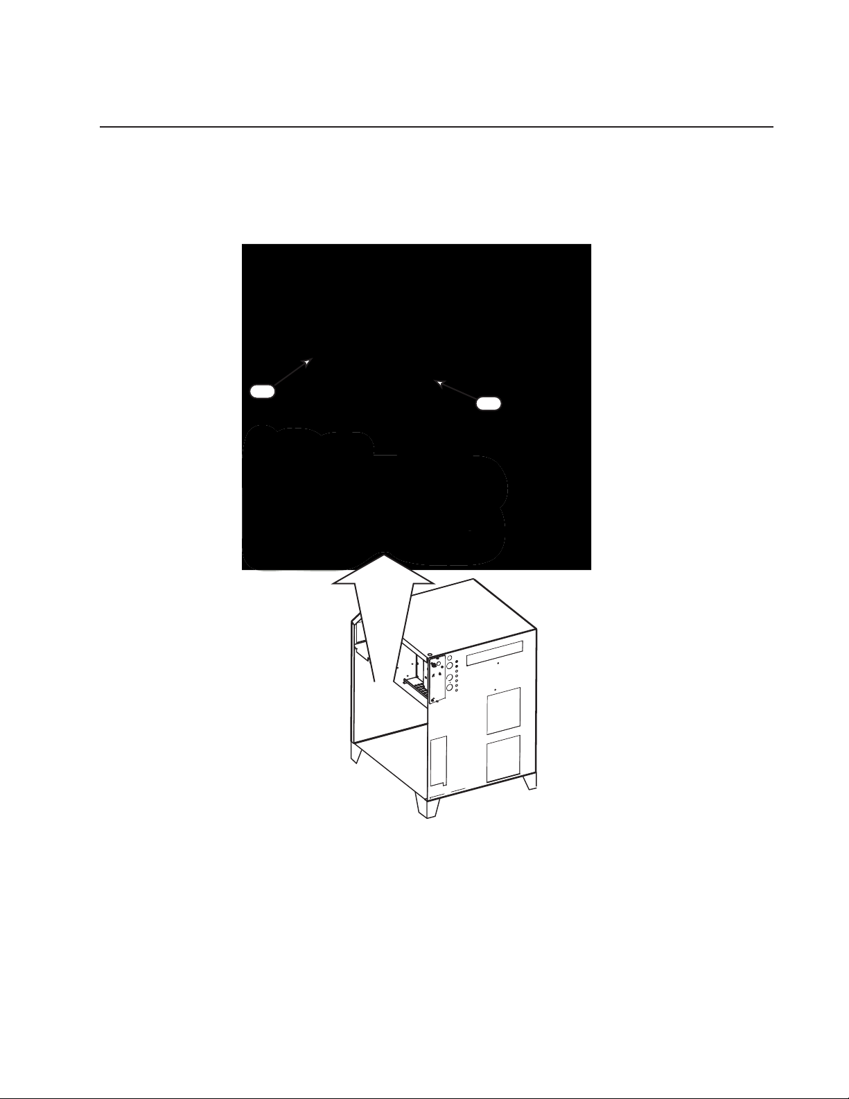
6.06 Power Supply Replacement Parts - Right Side
Item # Qty Description Ref. Des. Catalog #
1 1 Heat Exchanger Fan FAN1 9-9338
2 1 Radiator 9-9339
2
1
Art # A-08308
Manual No. 0-5056 6-9 Power Supply Parts List
Page 92

6.07 Power Supply Replacement Parts - Right Side
Item # Qty Description Ref. Des. Catalog #
1 1 Output Filter PC PCB8 9-9341
2 1 Sensor HCT2 9-9368
3 1 Magnetic Contactor, pilot MC2 9-9343
4 1 Resistor R6 9-9340
5 1 Resistor R9
6 1 Capacitor C2
1
2
3
Art # A-08309
4
5
6
Manual No. 0-5056 6-10 Power Supply Parts List
Page 93

6.08 Power Supply Replacement Parts - Right Side
Item # Qty Description Ref. Des. Catalog #
1 Chopper Module 9-9389
1 Sensor HCT1 9-9342
Chopper Module
HCT1
Art # A-08311
Manual No. 0-5056 6-11 Power Supply Parts List
Page 94
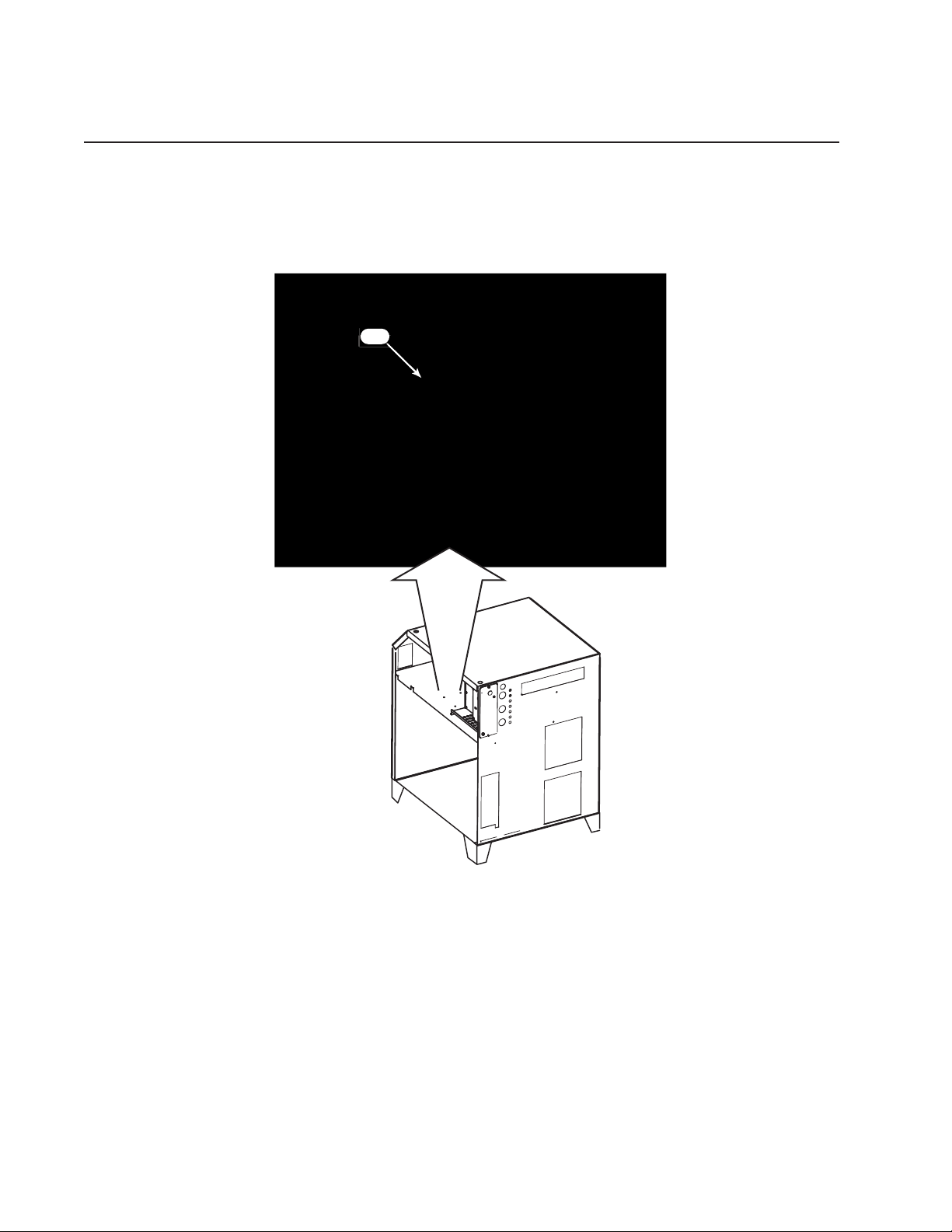
6.09 Power Supply Replacement Parts - Front Panel
Item # Qty Description Ref. Des. Catalog #
7 1 Main Power Switch (‘Circuit Protector’) CP1 9-9344
for 230-400-460 VAC units
7
Art # A-08312
Manual No. 0-5056 6-12 Power Supply Parts List
Page 95
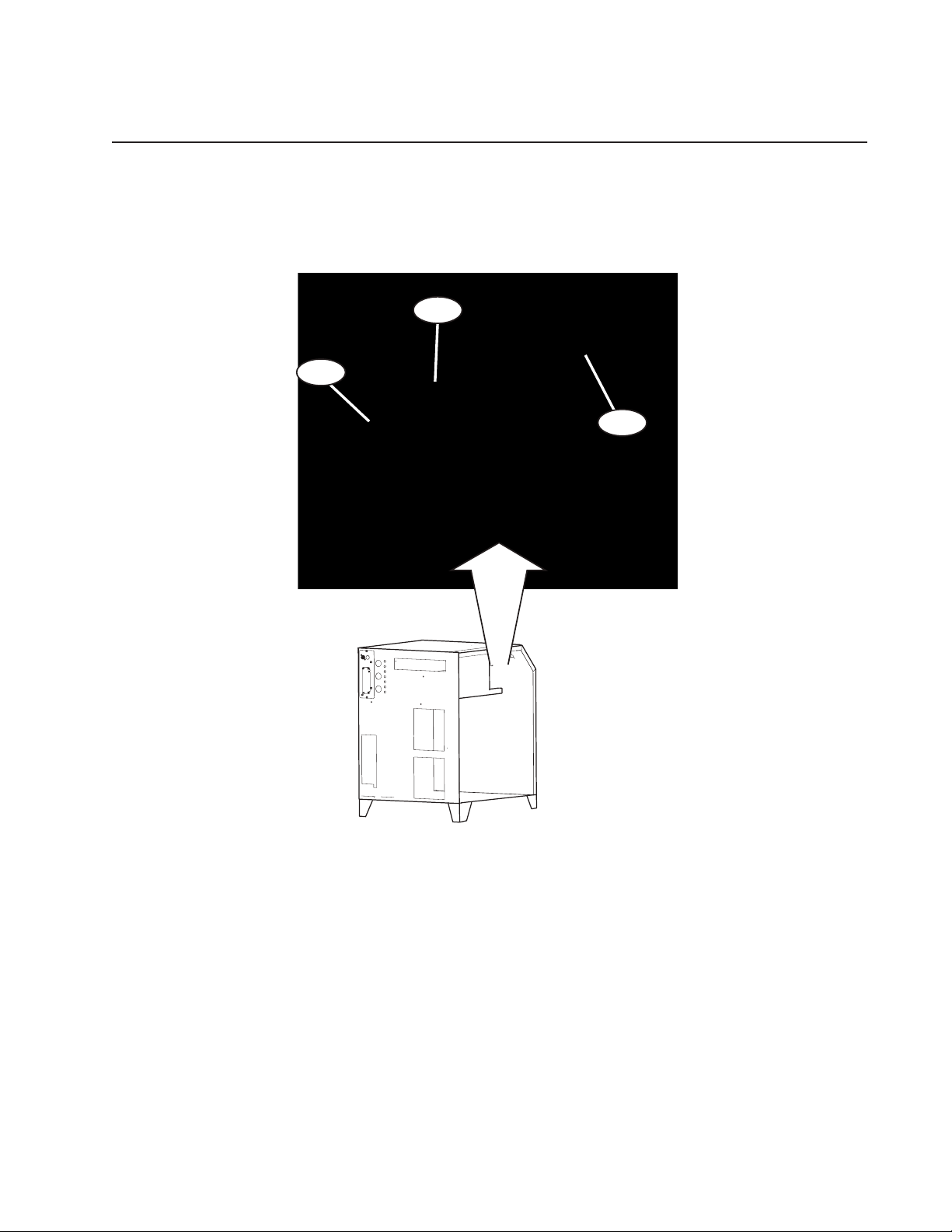
6.10 Power Supply Replacement Parts - Front Panel
Item # Qty Description Ref. Des. Catalog #
1 PC Board PCB3 9-9365
1 PC Board 230/460VAC PCB4 9-9370
1 PC Board 600VAC PCB4 9-9492
1 Display PC Board PCB6 9-9347
PCB3
PCB4
PCB6
Art # A-08313
Manual No. 0-5056 6-13 Power Supply Parts List
Page 96
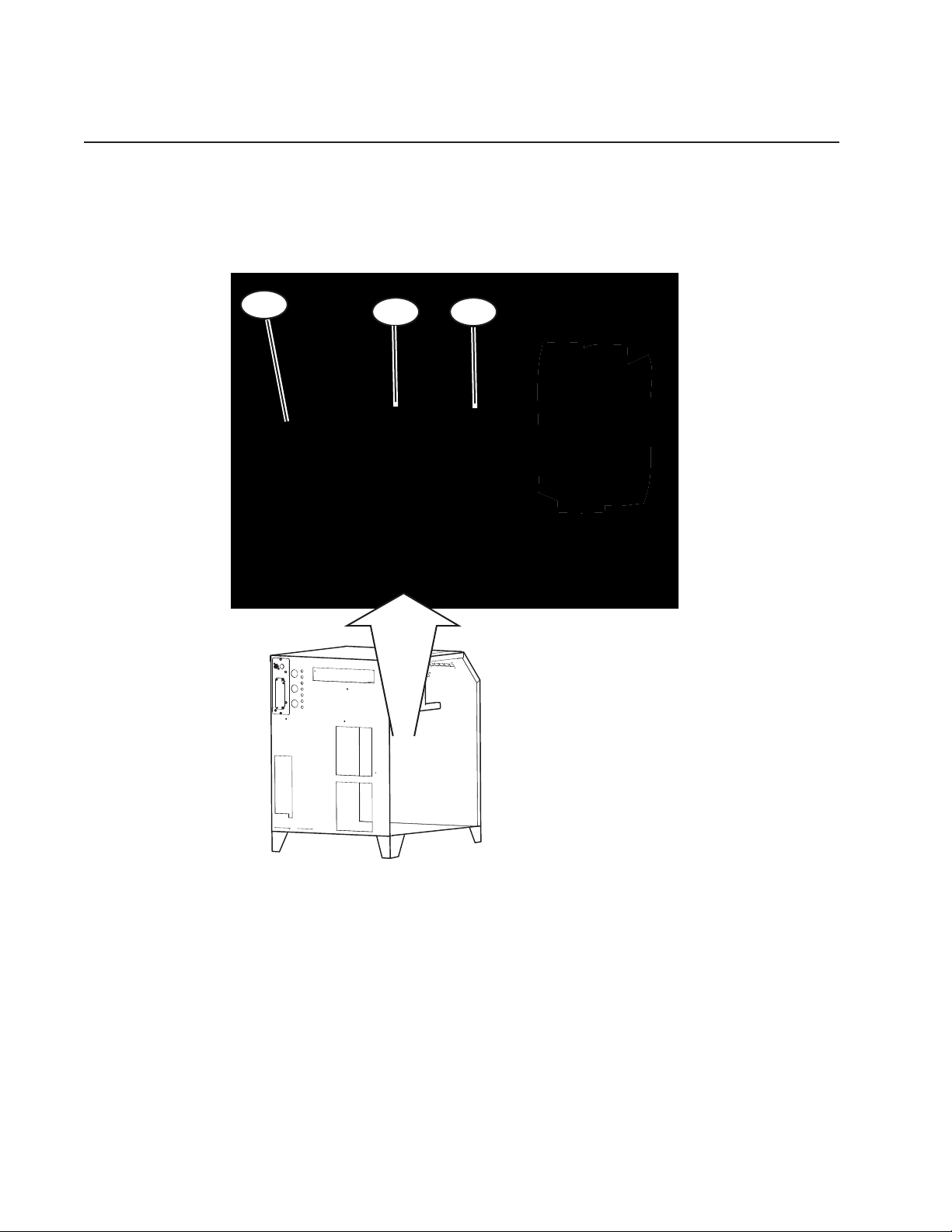
6.11 Power Supply Replacement Parts - Right Side
Item # Qty Description Ref. Des. Catalog #
1 1 PCBoard 230-400-460VAC PCB1 9-9362
1 1 PCBoard 600VAC PCB1 9-9491
2 1 Magnetic Contactor MC1,MC3 9-9364
1
2
2
Art # A-08314
Manual No. 0-5056 6-14 Power Supply Parts List
Page 97

6.12 Power Supply Replacement Parts - Rear Panel
RAS
125V 2.5A
CCM
125V3.15A
GCM
125V 10A
GCM
125V2.5A
GCM
125V2.5A
PUMP
250V 10A
FAN
125V 3.15A
CIRCUIT
BREAKERS
J55
J59
J15
G
C
M
C
N
C
R
A
S
CP2
CP3
CP4
CP5
CP6
CP7
CP8
12
13
14
15
16
17
18
Art # A-06017_AC
Item # Qty Description Breaker Rating Cicuit Rating Ref. Des. Catalog #
12 1 Circuit Breaker (RAS) 125V, 2.5 A 120VAC @ 1A CP2 9-9348
13 1 Circuit Breaker (’TDC’) 125V, 3.15A 24VAC @ 1A CP3 9-9349
14 1 Circuit Breaker (AGC) 125V, 10A 24VAC @ 5A CP4 9-9350
15 1 Circuit Breaker (AGC) 125V, 2.5A 120VAC @ 1A CP5 9-9348
16 1 Circuit Breaker (AGC) 125V, 2.5A 15VDC @ 1A CP6 9-9348
17 1 Circuit Breaker (Pump) 250V, 10A 200VAC @ 3A CP7 9-9351
18 1 Circuit Breaker (Fan) 125V, 3.15A 24VDC @ 1A CP8 9-9349
1 Coolant Tank 9-5948
1 Tank Cap 8-5142
1 Filter, Coolant 8-4276
COOLANT
RETURN
SUPPLY
Tank Cap
Filter
Coolant Tank
Art # A-04932_AB
Manual No. 0-5056 6-15 Power Supply Parts List
Page 98
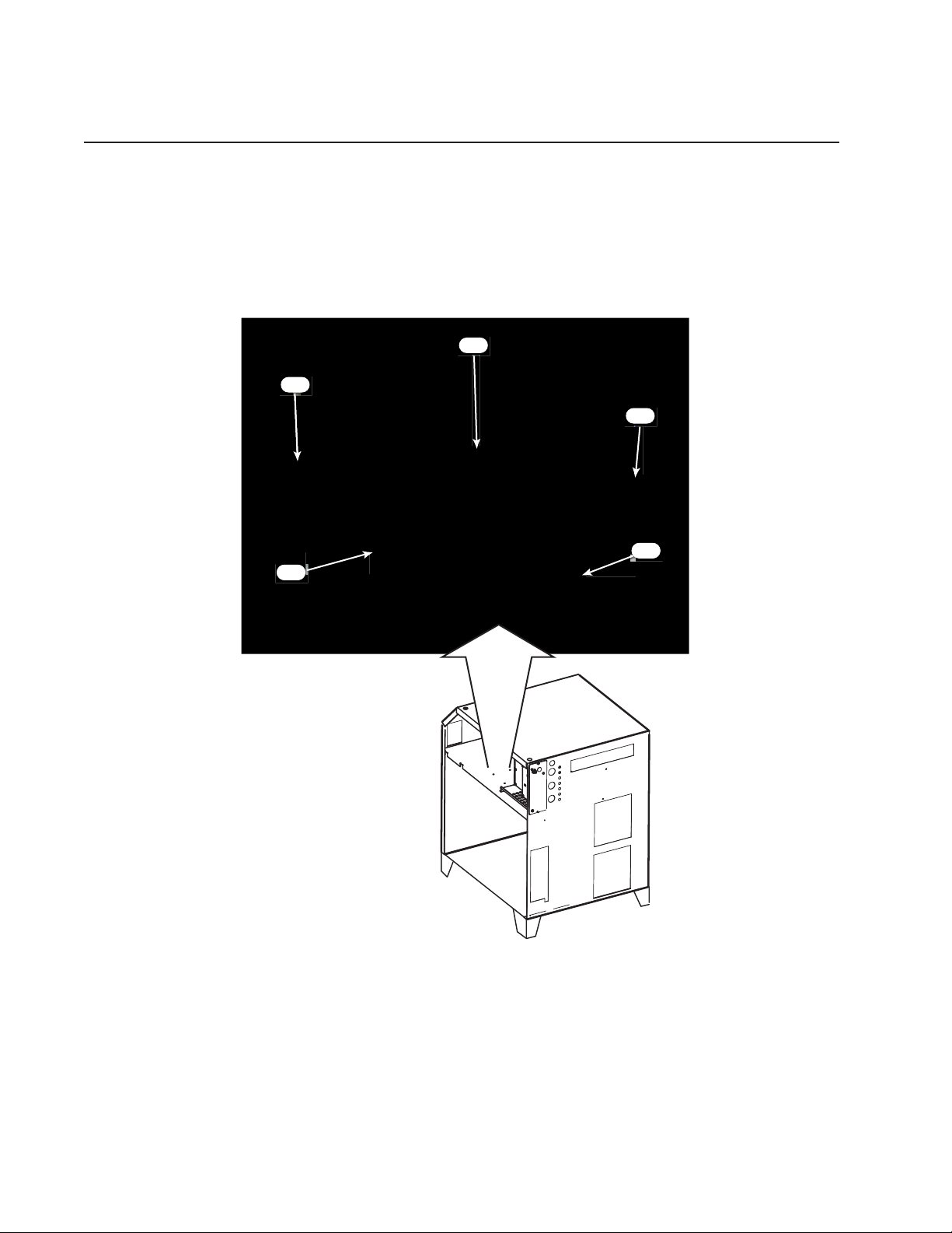
6.13 Power Supply Replacement Parts - Right Side
Item # Qty Description Ref. Des. Catalog #
1 1 Resistor R7 9-9363
2 1 Rectifier (Diode) D1 9-9345
3 1 Transformer T1 9-9355
for 230/460 VAC units
4 1 Diode D2 9-9486
5 1 Terminal Strip TB3 N/A
3
2
4
1
5
Art # A-08310
Manual No. 0-5056 6-16 Power Supply Parts List
Page 99
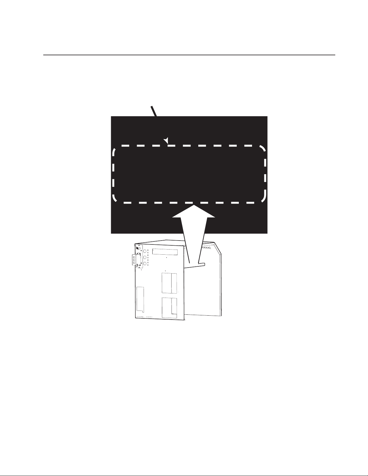
6.14 Power Supply Replacement Parts
Item # Qty Description Catalog #
29 2 Inverter Module 208/230V 9-9360D
2 Inverter Module 400V CE and 400V Non CE9-9482D
2 Inverter Module 600V 9-9485D
Art # A-04786
Manual No. 0-5056 6-17 Power Supply Parts List
Page 100

6.15 Power Supply Replacement Parts - Right Side
Item # Qty Description Ref. Des. Catalog #
30 1 Sensor (Thermistor) TH1 9-9361
Manual No. 0-5056 6-18 Power Supply Parts List
 Loading...