

Page 1

400 MST
®
ARCMASTER
INVERTER ARC WELDER
Operating Manual
Art # A-07368
Version No: 1 Issue Date: April 26, 2006 Manual No.: 0-4905
INVERTER
Operating Features:
GMAW
FCAW
50
3
GTAWCAGSMAW
PHASE
60
Hz
DC
CC
CV
400
V
Page 2

WE APPRECIA TE YOUR BUSINESS!
Congratulations on your new Thermal Arc product. We are proud
to have you as our customer and will strive to provide you with
the best service and reliability in the industry. This product is backed
by our extensive warranty and world-wide service network. To
locate your nearest distributor or service agency call
1-800-752-7621, or visit us on the web at www.thermalarc.com.
This Operating Manual has been designed to instruct you on the
correct use and operation of your Thermal Arc product. Your
satisfaction with this product and its safe operation is our ultimate
concern. Therefore please take the time to read the entire manual,
especially the Safety Precautions. They will help you to avoid
potential hazards that may exist when working with this product.
YOU ARE IN GOOD COMPANY!
The Brand of Choice for Contractors and Fabricators Worldwide.
Thermal Arc is a Global Brand of Arc Welding Products for
Thermadyne Industries Inc. We manufacture and supply to major
welding industry sectors worldwide including; Manufacturing,
Construction, Mining, Automotive, Aerospace, Engineering, Rural
and DIY/Hobbyist.
We distinguish ourselves from our competition through marketleading, dependable products that have stood the test of time. We
pride ourselves on technical innovation, competitive prices,
excellent delivery, superior customer service and technical support,
together with excellence in sales and marketing expertise.
Above all, we are committed to develop technologically advanced
products to achieve a safer working environment within the welding
industry.
Page 3

WARNINGS
Read and understand this entire Manual and your employer’s safety practices before installing,
operating, or servicing the equipment.
While the information contained in this Manual represents the Manufacturer's best judgement,
the Manufacturer assumes no liability for its use.
ArcMaster 400 MST Inverter Arc Welder
Instruction Manual Number 0-4905 for:
Part Number 10-3089
Published by:
Thermadyne Industries Inc.
82 Benning Street
West Lebanon, New Hampshire, USA 03784
(603) 298-5711
www.thermalarc.com
Copyright 2006 by
Thermadyne Industries Inc.
All rights reserved.
Reproduction of this work, in whole or in part, without written permission of the publisher
is prohibited.
The publisher does not assume and hereby disclaims any liability to any party for any
loss or damage caused by any error or omission in this Manual, whether such error
results from negligence, accident, or any other cause.
Publication Date: April 26, 2006
Record the following information for Warranty purposes:
Where Purchased: ___________________________________
Purchase Date: ___________________________________
Equipment Serial #: ___________________________________
Page 4

TABLE OF CONTENTS
SECTION 1: SAFETY INSTRUCTIONS AND WARNINGS ................................................................. 1
SYMBOL LEGEND................................................................................................................. 11
SECTION 2: INTRODUCTION AND DESCRIPTION .......................................................................12
2.01 How to Use This Manual.............................................................................................................................12
2.02 Equipment Identification .............................................................................................................................12
2.03 Receipt of Equipment..................................................................................................................................12
2.04 Description .................................................................................................................................................13
2.05 Functional Block Diagram ...........................................................................................................................14
2.06 Transporting Methods.................................................................................................................................14
SECTION 3: INSTALLATION RECOMMENDATIONS..................................................................... 15
3.01 Environment ...............................................................................................................................................15
3.02 Location......................................................................................................................................................15
3.03 Electrical Input Connections........................................................................................................................15
3.04 Electrical Input Requirements ..................................................................................................................... 16
3.05 Input Power ................................................................................................................................................ 17
3.06 High Frequency Introduction.......................................................................................................................17
3.07 High Frequency Interference.......................................................................................................................18
3.08 Duty Cycle...................................................................................................................................................18
3.09 Specifications .............................................................................................................................................19
SECTION 4: OPERATOR CONTROLS ...................................................................................... 20
4.01 ARC MASTER 400 MST Controls................................................................................................................20
4.02 Weld Parameter Descriptions for ARC MASTER 400 MST ..........................................................................23
4.03 Weld Process Selection for the ARC MASTER 400 MST .............................................................................24
4.04 Weld Parameter Descriptions......................................................................................................................24
4.05 Weld Parameters.........................................................................................................................................26
4.06 Power Source Features...............................................................................................................................26
SECTION 5: SEQUENCE OF OPERATION ................................................................................. 28
5.01 Stick Welding.............................................................................................................................................. 29
5.02 LIFT TIG Welding ........................................................................................................................................ 29
5.03 MIG Welding...............................................................................................................................................30
5.04 Save-Load Operation...................................................................................................................................30
SECTION 6: BASIC TIG WELDING GUIDE................................................................................. 31
6.01 Electrode Polarity........................................................................................................................................ 31
6.02 Tungsten Electrode Current Ranges............................................................................................................31
6.03 Tungsten Electrode Types...........................................................................................................................31
6.04 Guide for Selecting Filler Wire Diameter......................................................................................................32
6.05 Shielding Gas Selection...............................................................................................................................32
6.06 TIG Welding Parameters for Low Carbon & Low Alloy Steel Pipe ...............................................................32
6.07 Welding Parameters for Steel......................................................................................................................33
Page 5

TABLE OF CONTENTS
SECTION 7: BASIC STICK WELDING GUIDE............................................................................. 34
7.01 Electrode Polarity........................................................................................................................................ 34
7.02 Effects of Stick Welding Various Materials..................................................................................................34
SECTION 8.0 BASIC MIG WELDING GUIDE ............................................................................... 36
8.01 Setting of the Power Source .......................................................................................................................36
8.02 Position of MIG Torch................................................................................................................................. 36
8.03 Distance from the MIG Torch Nozzle to the Work Piece.............................................................................. 36
8.04 Travel Speed............................................................................................................................................... 37
8.05 Electrode Wire Size Selection......................................................................................................................37
8.06 Deposition Rate Comparison.......................................................................................................................37
SECTION 9: ROUTINE MAINTENANCE.................................................................................... 38
SECTION 10: BASIC TROUBLESHOOTING................................................................................. 39
10.01 Solving MIG Problems beyond the Welding Terminals..............................................................................39
10.02 MIG Welding Problems.............................................................................................................................41
10.03 TIG Welding Problems..............................................................................................................................43
10.04 Stick Welding Problems............................................................................................................................45
10.05 Power Source Problems ...........................................................................................................................47
SECTION 11: VOLTAGE REDUCTION DEVICE (VRD)..................................................................... 49
11.01 VRD Specification ..................................................................................................................................... 49
11.02 VRD Maintenance .....................................................................................................................................49
11.03 Switching VRD On/Off...............................................................................................................................50
SECTION 12: POWER SOURCE ERROR CODES .......................................................................... 52
APPENDIX A - INTERCONNECT DIAGRAM .................................................................................... 55
APPENDIX B - ARCMASTER 400 MST ACCESSORIES....................................................................... 57
LIMITED WARRANTY AND SCHEDULE
GLOBAL CUSTOMER SERVICE CONTACT INFORMATION.................................................Inside Rear Cover
Page 6

Page 7

ARCMASTER 400 MST
SECTION 1:
SAFETY INSTRUCTIONS AND WARNINGS
WARNING
!
PROTECT YOURSELF AND OTHERS FROM POSSIBLE SERIOUS INJURY OR DEATH. KEEP CHILDREN AWAY. PACEMAKER WEARERS KEEP
AWAY UNTIL CONSULTING YOUR DOCTOR. DO NOT LOSE THESE INSTRUCTIONS. READ OPERATING/INSTRUCTION MANUAL BEFORE
INSTALLING, OPERATING OR SERVICING THIS EQUIPMENT.
Welding products and welding processes can cause serious injury or death, or damage to other equipment or property, if the operator does not
strictly observe all safety rules and take precautionary actions.
Safe practices have developed from past experience in the use of welding and cutting. These practices must be learned through study and
training before using this equipment. Some of these practices apply to equipment connected to power lines; other practices apply to engine
driven equipment. Anyone not having extensive training in welding and cutting practices should not attempt to weld.
Safe practices are outlined in the American National Standard Z49.1 entitled:
guides to what you should learn before operating this equipment are listed at the end of these safety precautions. HAVE ALL INSTALLATION,
OPERATION, MAINTENANCE, AND REPAIR WORK PERFORMED ONLY BY QUALIFIED PEOPLE.
1.01 Arc Welding Hazards
WARNING
ELECTRIC SHOCK can kill.
Touching live electrical parts can cause fatal shocks or
severe burns. The electrode and work circuit is electrically
live whenever the output is on. The input power circuit
and machine internal circuits are also live when power
is on. In semiautomatic or automatic wire welding, the
wire, wire reel, drive roll housing, and all metal parts
touching the welding wire are electrically live. Incorrectly
installed or improperly grounded equipment is a hazard.
SAFETY IN WELDING AND CUTTING. This publication and other
7. Use fully insulated electrode holders. Never dip holder in water to
cool it or lay it down on the ground or the work surface. Do not
touch holders connected to two welding machines at the same
time or touch other people with the holder or electrode.
8. Do not use worn, damaged, undersized, or poorly spliced cables.
9. Do not wrap cables around your body.
10. Ground the workpiece to a good electrical (earth) ground.
11. Do not touch electrode while in contact with the work (ground)
circuit.
12. Use only well-maintained equipment. Repair or replace damaged
parts at once.
13. In confined spaces or damp locations, do not use a welder with
AC output unless it is equipped with a voltage reducer. Use
equipment with DC output.
14. Wear a safety harness to prevent falling if working above floor
level.
1. Do not touch live electrical parts.
2. Wear dry, hole-free insulating gloves and body protection.
3. Insulate yourself from work and ground using dry insulating mats
or covers.
4. Disconnect input power or stop engine before installing or
servicing this equipment. Lock input power disconnect switch
open, or remove line fuses so power cannot be turned on
accidentally.
5. Properly install and ground this equipment according to its Owner’s
Manual and national, state, and local codes.
6. Turn off all equipment when not in use. Disconnect power to
equipment if it will be left unattended or out of service.
15. Keep all panels and covers securely in place.
WARNING
ARC RAYS can burn eyes and skin; NOISE can damage
hearing. Arc rays from the welding process produce
intense heat and strong ultraviolet rays that can burn
eyes and skin. Noise from some processes can damage
hearing.
1. Wear a welding helmet fitted with a proper shade of filter (see
ANSI Z49.1 listed in Safety Standards) to protect your face and
eyes when welding or watching.
2. Wear approved safety glasses. Side shields recommended.
1
Page 8

ARCMASTER 400 MST
3. Use protective screens or barriers to protect others from flash
and glare; warn others not to watch the arc.
4. Wear protective clothing made from durable, flame-resistant
material (wool and leather) and foot protection.
5. Use approved ear plugs or ear muffs if noise level is high.
WARNING
WARNING
WELDING can cause fire or explosion.
Sparks and spatter fly off from the welding arc. The flying
sparks and hot metal, weld spatter, hot workpiece, and
hot equipment can cause fires and burns. Accidental
contact of electrode or welding wire to metal objects
can cause sparks, overheating, or fire.
FUMES AND GASES can be hazardous to your health.
Welding produces fumes and gases. Breathing these
fumes and gases can be hazardous to your health.
1. Keep your head out of the fumes. Do not breath the fumes.
2. If inside, ventilate the area and/or use exhaust at the arc to remove
welding fumes and gases.
3. If ventilation is poor, use an approved air-supplied respirator.
4. Read the Material Safety Data Sheets (MSDSs) and the
manufacturer’s instruction for metals, consumables, coatings, and
cleaners.
5. Work in a confined space only if it is well ventilated, or while
wearing an air-supplied respirator. Shielding gases used for
welding can displace air causing injury or death. Be sure the
breathing air is safe.
6. Do not weld in locations near degreasing, cleaning, or spraying
operations. The heat and rays of the arc can react with vapors to
form highly toxic and irritating gases.
7. Do not weld on coated metals, such as galvanized, lead, or
cadmium plated steel, unless the coating is removed from the
weld area, the area is well ventilated, and if necessary, while
wearing an air-supplied respirator. The coatings and any metals
containing these elements can give off toxic fumes if welded.
1. Protect yourself and others from flying sparks and hot metal.
2. Do not weld where flying sparks can strike flammable material.
3. Remove all flammables within 35 ft (10.7 m) of the welding arc.
If this is not possible, tightly cover them with approved covers.
4. Be alert that welding sparks and hot materials from welding can
easily go through small cracks and openings to adjacent areas.
5. Watch for fire, and keep a fire extinguisher nearby.
6. Be aware that welding on a ceiling, floor, bulkhead, or partition
can cause fire on the hidden side.
7. Do not weld on closed containers such as tanks or drums.
8. Connect work cable to the work as close to the welding area as
practical to prevent welding current from traveling long, possibly
unknown paths and causing electric shock and fire hazards.
9. Do not use welder to thaw frozen pipes.
10. Remove stick electrode from holder or cut off welding wire at
contact tip when not in use.
Eye protection filter shade selector for welding or cutting
Welding or cutting Electrode Size Filter Welding or cutting Electrode Size Filter
Torch soldering 2 Gas metal-arc
Torch brazing 3 or 4 Non-ferrous base metal All 11
Oxygen C utting Ferrous base metal All 12
Light Under 1 in., 25 mm 3 or 4 Gas tungsten arc welding All 12
Medium 1 to 6 in., 25-150 mm 4 or 5 (TIG) All 12
Heavy Over 6 in., 150 mm 5 or 6 Atomic hydrogen welding All 12
Gas welding Carbon arc welding All 12
Light Under 1/8 in., 3 mm 4 or 5 Plasma arc welding
Medium 1/8 to 1/2 in., 3-12 mm 5 or 6 Carbon arc air gouging
Heavy Over 1/2 in., 12 mm 6 or 8 Light 12
Shielded metal-arc Under 5/32 in., 4 mm 10 Heavy 14
5/32 to 1/4 in., 12 Plasma arc cutting
Over 1/4 in., 6.4 mm 14 Light Under 300 Amp 9
(goggles or helmet), from AWS A6.2-73.
Medium 300 to 400 Amp 12
Heavy Over 400 Amp 14
2
Page 9

WARNING
ARCMASTER 400 MST
2. If used in a closed area, vent engine exhaust outside and away
from any building air intakes.
FLYING SPARKS AND HOT METAL can cause injury.
Chipping and grinding cause flying metal. As welds cool,
they can throw off slag.
1. Wear approved face shield or safety goggles. Side shields
recommended.
2. Wear proper body protection to protect skin.
WARNING
CYLINDERS can explode if damaged.
Shielding gas cylinders contain gas under high pressure.
If damaged, a cylinder can explode. Since gas cylinders
are normally part of the welding process, be sure to treat
them carefully.
1. Protect compressed gas cylinders from excessive heat, mechanical
shocks, and arcs.
2. Install and secure cylinders in an upright position by chaining
them to a stationary support or equipment cylinder rack to prevent
falling or tipping.
3. Keep cylinders away from any welding or other electrical circuits.
4. Never allow a welding electrode to touch any cylinder.
5. Use only correct shielding gas cylinders, regulators, hoses, and
fittings designed for the specific application; maintain them and
associated parts in good condition.
6. Turn face away from valve outlet when opening cylinder valve.
7. Keep protective cap in place over valve except when cylinder is in
use or connected for use.
8. Read and follow instructions on compressed gas cylinders,
associated equipment, and CGA publication P-1 listed in Safety
Standards.
WARNING
ENGINE FUEL can cause fire or explosion.
Engine fuel is highly flammable.
1. Stop engine before checking or adding fuel.
2. Do not add fuel while smoking or if unit is near any sparks or
open flames.
3. Allow engine to cool before fueling. If possible, check and add
fuel to cold engine before beginning job.
4. Do not overfill tank — allow room for fuel to expand.
5. Do not spill fuel. If fuel is spilled, clean up before starting engine.
WARNING
MOVING PARTS can cause injury.
Moving parts, such as fans, rotors, and belts can cut fingers and hands
and catch loose clothing.
1. Keep all doors, panels, covers, and guards closed and
securely in place.
2. Stop engine before installing or connecting unit.
3. Have only qualified people remove guards or covers for
maintenance and troubleshooting as necessary.
4. To prevent accidental starting during servicing, disconnect
negative (-) battery cable from battery.
5. Keep hands, hair, loose clothing, and tools away from moving
parts.
6. Reinstall panels or guards and close doors when servicing
is finished and before starting engine.
WARNING
!
Engines can be dangerous.
WARNING
ENGINE EXHAUST GASES can kill.
Engines produce harmful exhaust gases.
1. Use equipment outside in open, well-ventilated areas.
WARNING
SPARKS can cause BATTERY GASES TO EXPLODE;
BATTERY ACID can burn eyes and skin.
Batteries contain acid and generate explosive gases.
1. Always wear a face shield when working on a battery.
2. Stop engine before disconnecting or connecting battery cables.
3. Do not allow tools to cause sparks when working on a battery.
4. Do not use welder to charge batteries or jump start vehicles.
5. Observe correct polarity (+ and –) on batteries.
3
Page 10

ARCMASTER 400 MST
1.02 Principal Safety Standards
WARNING
STEAM AND PRESSURIZED HOT COOLANT can burn
face, eyes, and skin.
The coolant in the radiator can be very hot and under
pressure.
1. Do not remove radiator cap when engine is hot. Allow engine to cool.
2. Wear gloves and put a rag over cap area when removing cap.
3. Allow pressure to escape before completely removing cap.
WARNING
!
This product, when used for welding or cutting, produces
fumes or gases which contain chemicals know to the
State of California to cause birth defects and, in some
cases, cancer. (California Health & Safety code Sec.
25249.5 et seq.)
NOTE
Considerations About Welding And The Effects of Low
Frequency Electric and Magnetic Fields
Safety in Welding and Cutting, ANSI Standard Z49.1, from American
Welding Society, 550 N.W. LeJeune Rd., Miami, FL 33126.
Safety and Health Standards, OSHA 29 CFR 1910, from Superintendent
of Documents, U.S. Government Printing Office, Washington, D.C.
20402.
Recommended Safe Practices for the Preparation for Welding and
Cutting of Containers That Have Held Hazardous Substances, American Welding Society Standard AWS F4.1, from American Welding
Society, 550 N.W. LeJeune Rd., Miami, FL 33126.
National Electrical Code, NFPA Standard 70, from National Fire
Protection Association, Batterymarch Park, Quincy, MA 02269.
Safe Handling of Compressed Gases in Cylinders, CGA Pamphlet P1, from Compressed Gas Association, 1235 Jefferson Davis Highway,
Suite 501, Arlington, VA 22202.
Code for Safety in Welding and Cutting, CSA Standard W117.2, from
Canadian Standards Association, Standards Sales, 178 Rexdale
Boulevard, Rexdale, Ontario, Canada M9W 1R3.
Safe Practices for Occupation and Educational Eye and Face Protection, ANSI Standard Z87.1, from American National Standards Institute, 1430 Broadway, New York, NY 10018.
Cutting and Welding Processes, NFPA Standard 51B, from National
Fire Protection Association, Batterymarch Park, Quincy, MA 02269.
The following is a quotation from the General Conclusions Section of
the U.S. Congress, Office of Technology Assessment, Biological Effects
of Power Frequency Electric & Magnetic Fields - Background Paper,
OTA-BP-E-63 (Washington, DC: U.S. Government Printing Office, May
1989): “...there is now a very large volume of scientific findings based
on experiments at the cellular level and from studies with animals and
people which clearly establish that low frequency magnetic fields
interact with, and produce changes in, biological systems. While most
of this work is of very high quality, the results are complex. Current
scientific understanding does not yet allow us to interpret the evidence
in a single coherent framework. Even more frustrating, it does not yet
allow us to draw definite conclusions about questions of possible risk
or to offer clear science-based advice on strategies to minimize or
avoid potential risks.”
To reduce magnetic fields in the workplace, use the following
procedures:
1. Keep cables close together by twisting or taping them.
2. Arrange cables to one side and away from the operator.
3. Do not coil or drape cable around the body.
4. Keep welding power source and cables as far away from
body as practical.
ABOUT PACEMAKERS:
The above procedures are among those also normally
recommended for pacemaker wearers. Consult your
doctor for complete information.
4
Page 11

ARCMASTER 400 MST
1.03 Precautions de Securite en Soudage à l’Arc
MISE EN GARDE
!
LE SOUDAGE A L’ARC EST DANGEREUX
PROTEGEZ-VOUS, AINSI QUE LES AUTRES, CONTRE LES BLESSURES GRAVES POSSIBLES OU LA MORT. NE LAISSEZ PAS LES ENFANTS
S’APPROCHER, NI LES PORTEURS DE STIMULATEUR CARDIAQUE (A MOINS QU’ILS N’AIENT CONSULTE UN MEDECIN). CONSERVEZ CES
INSTRUCTIONS. LISEZ LE MANUEL D’OPERATION OU LES INSTRUCTIONS AVANT D’INSTALLER, UTILISER OU ENTRETENIR CET EQUIPEMENT.
Les produits et procédés de soudage peuvent sauser des blessures graves ou la mort, de même que des dommages au reste du matériel et à la
propriété, si l’utilisateur n’adhère pas strictement à toutes les règles de sécurité et ne prend pas les précautions nécessaires.
En soudage et coupage, des pratiques sécuritaires se sont développées suite à l’expérience passée. Ces pratiques doivent être apprises par
étude ou entraînement avant d’utiliser l’equipement. Toute personne n’ayant pas suivi un entraînement intensif en soudage et coupage ne devrait
pas tenter de souder. Certaines pratiques concernent les équipements raccordés aux lignes d’alimentation alors que d’autres s’adressent aux
groupes électrogènes.
La norme Z49.1 de l’American National Standard, intitulée “SAFETY IN WELDING AND CUTTING” présente les pratiques sécuritaires à suivre.
Ce document ainsi que d’autres guides que vous devriez connaître avant d’utiliser cet équipement sont présentés à la fin de ces instructions de
sécurité.
SEULES DES PERSONNES QUALIFIEES DOIVENT FAIRE DES TRAVAUX D’INSTALLATION, DE REPARATION, D’ENTRETIEN ET D’ESSAI.
1.04 Dangers Relatifs au Soudage à l’Arc
AVERTISSEMENT
L’ELECTROCUTION PEUT ETRE MORTELLE.
Une décharge électrique peut tuer ou brûler gravement.
L’électrode et le circuit de soudage sont sous tension
dès la mise en circuit. Le circuit d’alimentation et les
circuits internes de l’équipement sont aussi sous tension dès la mise en marche. En soudage automatique
ou semi-automatique avec fil, ce dernier, le rouleau ou
la bobine de fil, le logement des galets d’entrainement
et toutes les pièces métalliques en contact avec le fil de
soudage sont sous tension. Un équipement
inadéquatement installé ou inadéquatement mis à la terre
est dangereux.
1. Ne touchez pas à des pièces sous tension.
2. Portez des gants et des vêtements isolants, secs et non troués.
6. Arrêtez tout équipement après usage. Coupez l’alimentation de
l’équipement s’il est hors d’usage ou inutilisé.
7. N’utilisez que des porte-électrodes bien isolés. Ne jamais plonger
les porte-électrodes dans l’eau pour les refroidir. Ne jamais les
laisser traîner par terre ou sur les pièces à souder. Ne touchez
pas aux porte-électrodes raccordés à deux sources de courant en
même temps. Ne jamais toucher quelqu’un d’autre avec l’électrode
ou le porte-électrode.
8. N’utilisez pas de câbles électriques usés, endommagés, mal
épissés ou de section trop petite.
9. N’enroulez pas de câbles électriques autour de votre corps.
10. N’utilisez qu’une bonne prise de masse pour la mise à la terre de
la pièce à souder.
11. Ne touchez pas à l’électrode lorsqu’en contact avec le circuit de
soudage (terre).
12. N’utilisez que des équipements en bon état. Réparez ou remplacez
aussitôt les pièces endommagées.
13. Dans des espaces confinés ou mouillés, n’utilisez pas de source
de courant alternatif, à moins qu’il soit muni d’un réducteur de
tension. Utilisez plutôt une source de courant continu.
14. Portez un harnais de sécurité si vous travaillez en hauteur.
15. Fermez solidement tous les panneaux et les capots.
3 Isolez-vous de la pièce à souder et de la mise à la terre au moyen
de tapis isolants ou autres.
4. Déconnectez la prise d’alimentation de l’équipement ou arrêtez le
moteur avant de l’installer ou d’en faire l’entretien. Bloquez le
commutateur en circuit ouvert ou enlevez les fusibles de
l’alimentation afin d’éviter une mise en marche accidentelle.
5. Veuillez à installer cet équipement et à le mettre à la terre selon le
manuel d’utilisation et les codes nationaux, provinciaux et locaux
applicables.
5
Page 12

ARCMASTER 400 MST
AVERTISSEMENT
LE RAYONNEMENT DE L’ARC PEUT BRÛLER LES YEUX
ET LA PEAU; LE BRUIT PEUT ENDOMMAGER L’OUIE.
L’arc de soudage produit une chaleur et des rayons
ultraviolets intenses, susceptibles de brûler les yeux et
la peau. Le bruit causé par certains procédés peut
endommager l’ouïe.
1. Portez une casque de soudeur avec filtre oculaire de nuance
appropriée (consultez la norme ANSI Z49 indiquée ci-après) pour
vous protéger le visage et les yeux lorsque vous soudez ou que
vous observez l’exécution d’une soudure.
2. Portez des lunettes de sécurité approuvées. Des écrans latéraux
sont recommandés.
3. Entourez l’aire de soudage de rideaux ou de cloisons pour protéger
les autres des coups d’arc ou de l’éblouissement; avertissez les
observateurs de ne pas regarder l’arc.
4. Portez des vêtements en matériaux ignifuges et durables (laine et
cuir) et des chaussures de sécurité.
5. Portez un casque antibruit ou des bouchons d’oreille approuvés
lorsque le niveau de bruit est élevé.
AVERTISSEMENT
LES VAPEURS ET LES FUMEES SONT DANGEREUSES
POUR LA SANTE.
Le soudage dégage des vapeurs et des fumées
dangereuses à respirer.
1. Eloignez la tête des fumées pour éviter de les respirer.
2. A l’intérieur, assurez-vous que l’aire de soudage est bien ventilée
ou que les fumées et les vapeurs sont aspirées à l’arc.
3. Si la ventilation est inadequate, portez un respirateur à adduction
d’air approuvé.
4. Lisez les fiches signalétiques et les consignes du fabricant relatives aux métaux, aux produits consummables, aux revêtements
et aux produits nettoyants.
5. Ne travaillez dans un espace confiné que s’il est bien ventilé; sinon,
portez un respirateur à adduction d’air. Les gaz protecteurs de
soudage peuvent déplacer l’oxygène de l’air et ainsi causer des
malaises ou la mort. Assurez-vous que l’air est propre à la respiration.
6. Ne soudez pas à proximité d’opérations de dégraissage, de
nettoyage ou de pulvérisation. La chaleur et les rayons de l’arc
peuvent réagir avec des vapeurs et former des gaz hautement
toxiques et irritants.
SELECTION DES NUANCES DE FILTRES OCULAIRS POUR LA PROTECTION
DES YEUX EN COUPAGE ET SOUDAGE (selon AWS á 8.2-73)
Opération de coupage
ou soudage
Brassage tendre
au chalumeau
Brassage fort
au chalumeau
Oxycoupage métaux ferreux toutes conditions 12
mince moins de 1 po. (25 mm) 2 ou 3
moyen de 1 á 6 po. (25 á 150 mm) 4 ou 5
Soudage aux gaz Soudage á l'arc Plasma (PAW) toutes dimensions 12
mince moins de 1/8 po. (3 mm) 4 ou 5
moyen de 1/8 á 1/2 po. (3 á 12 mm) 5 ou 6 mince 12
Soudage á l'arc avec
électrode enrobees
(SMAW)
Dimension d'électrode ou
Epiasseur de métal ou
Intensité de courant
toutes conditions 2
toutes conditions 3 ou 4 métaux non-ferreux toutes conditions 11
épais plus de 6 po. (150 mm) 5 ou 6
épais plus de 1/2 po. (12 mm) 6 ou 8 épais 14
moins de 5/32 po. (4 mm) 10 Cou page á l'arc Plasma (PAC)
5/32 á 1/4 po. (4 á 6.4 mm) 12 mince moins de 300 amperès 9
plus de 1/4 po. (6.4 mm) 14 moyen de 300 á 400 amperès 12
Nuance de
filtre oculaire
Opération de coupage
ou soudage
Soudage á l'arc sous gaz
avec fil plein (GMAW)
Soudage á l'arc sous gaz avec
électrode de tungstène (GTAW)
Soudage á l'hydrogène
atomique (AHW)
Soudage á l'arc avec
électrode de carbone (CAW)
Gougeage Air-Arc avec
électrode de carbone
Dimension d'électrode ou
Epiasseur de métal ou
Intensité de courant
toutes conditions 12
toutes conditions 12
toutes conditions 12
épais plus de 400 amperès 14
Nuance de
filtre oculaire
6
Page 13

7. Ne soudez des tôles galvanisées ou plaquées au plomb ou au
cadmium que si les zones à souder ont été grattées à fond, que si
l’espace est bien ventilé; si nécessaire portez un respirateur à adduction d’air. Car ces revêtements et tout métal qui contient ces
éléments peuvent dégager des fumées toxiques au moment du
soudage.
AVERTISSEMENT
ARCMASTER 400 MST
AVERTISSEMENT
LES ETINCELLES ET LES PROJECTIONS BRULANTES
PEUVENT CAUSER DES BLESSURES.
Le piquage et le meulage produisent des particules
métalliques volantes. En refroidissant, la soudure peut
projeter du éclats de laitier.
LE SOUDAGE PEUT CAUSER UN INCENDIE OU UNE
EXPLOSION
L’arc produit des étincellies et des projections. Les
particules volantes, le métal chaud, les projections de
soudure et l’équipement surchauffé peuvent causer un
incendie et des brûlures. Le contact accidentel de
l’électrode ou du fil-électrode avec un objet métallique
peut provoquer des étincelles, un échauffement ou un
incendie.
1. Protégez-vous, ainsi que les autres, contre les étincelles et du
métal chaud.
2. Ne soudez pas dans un endroit où des particules volantes ou des
projections peuvent atteindre des matériaux inflammables.
3. Enlevez toutes matières inflammables dans un rayon de 10, 7
mètres autour de l’arc, ou couvrez-les soigneusement avec des
bâches approuvées.
4. Méfiez-vous des projections brulantes de soudage susceptibles
de pénétrer dans des aires adjacentes par de petites ouvertures
ou fissures.
5. Méfiez-vous des incendies et gardez un extincteur à portée de la
main.
6. N’oubliez pas qu’une soudure réalisée sur un plafond, un plancher,
une cloison ou une paroi peut enflammer l’autre côté.
7. Ne soudez pas un récipient fermé, tel un réservoir ou un baril.
8. Connectez le câble de soudage le plus près possible de la zone
de soudage pour empêcher le courant de suivre un long parcours
inconnu, et prévenir ainsi les risques d’électrocution et d’incendie.
9. Ne dégelez pas les tuyaux avec un source de courant.
10. Otez l’électrode du porte-électrode ou coupez le fil au tube-contact lorsqu’inutilisé après le soudage.
11. Portez des vêtements protecteurs non huileux, tels des gants en
cuir, une chemise épaisse, un pantalon revers, des bottines de
sécurité et un casque.
1. Portez un écran facial ou des lunettes protectrices
approuvées. Des écrans latéraux sont recommandés.
2. Portez des vêtements appropriés pour protéger la peau.
AVERTISSEMENT
LES BOUTEILLES ENDOMMAGEES PEUVENT
EXPLOSER
Les bouteilles contiennent des gaz protecteurs sous
haute pression. Des bouteilles endommagées peuvent
exploser. Comme les bouteilles font normalement partie
du procédé de soudage, traitez-les avec soin.
1. Protégez les bouteilles de gaz comprimé contre les sources de
chaleur intense, les chocs et les arcs de soudage.
2. Enchainez verticalement les bouteilles à un support ou à un cadre
fixe pour les empêcher de tomber ou d’être renversées.
3. Eloignez les bouteilles de tout circuit électrique ou de tout soudage.
4. Empêchez tout contact entre une bouteille et une électrode de
soudage.
5. N’utilisez que des bouteilles de gaz protecteur, des détendeurs,
des boyauxs et des raccords conçus pour chaque application
spécifique; ces équipements et les pièces connexes doivent être
maintenus en bon état.
6. Ne placez pas le visage face à l’ouverture du robinet de la bouteille
lors de son ouverture.
7. Laissez en place le chapeau de bouteille sauf si en utilisation ou
lorsque raccordé pour utilisation.
8. Lisez et respectez les consignes relatives aux bouteilles de gaz
comprimé et aux équipements connexes, ainsi que la publication
P-1 de la CGA, identifiée dans la liste de documents ci-dessous.
AVERTISSEMENT
LES MOTEURS PEUVENT ETRE DANGEREUX
LES GAZ D’ECHAPPEMENT DES MOTEURS PEUVENT
ETRE MORTELS.
Les moteurs produisent des gaz d’échappement nocifs.
7
Page 14

ARCMASTER 400 MST
1. Utilisez l’équipement à l’extérieur dans des aires ouvertes et bien
ventilées.
Les accumulateurs contiennent de l’électrolyte acide et
dégagent des vapeurs explosives.
2. Si vous utilisez ces équipements dans un endroit confiné, les
fumées d’échappement doivent être envoyées à l’extérieur, loin
des prises d’air du bâtiment.
AVERTISSEMENT
LE CARBURANT PEUR CAUSER UN INCENDIE OU UNE
EXPLOSION.
Le carburant est hautement inflammable.
1. Arrêtez le moteur avant de vérifier le niveau e carburant ou de
faire le plein.
2. Ne faites pas le plein en fumant ou proche d’une source d’étincelles
ou d’une flamme nue.
3. Si c’est possible, laissez le moteur refroidir avant de faire le plein
de carburant ou d’en vérifier le niveau au début du soudage.
4. Ne faites pas le plein de carburant à ras bord: prévoyez de l’espace
pour son expansion.
5. Faites attention de ne pas renverser de carburant. Nettoyez tout
carburant renversé avant de faire démarrer le moteur.
AVERTISSEMENT
1. Portez toujours un écran facial en travaillant sur un accumu-lateur.
2. Arrêtez le moteur avant de connecter ou de déconnecter des câbles
d’accumulateur.
3. N’utilisez que des outils anti-étincelles pour travailler sur un
accumulateur.
4. N’utilisez pas une source de courant de soudage pour charger
un accumulateur ou survolter momentanément un véhicule.
5. Utilisez la polarité correcte (+ et –) de l’accumulateur.
AVERTISSEMENT
LA VAPEUR ET LE LIQUIDE DE REFROIDISSEMENT
BRULANT SOUS PRESSION PEUVENT BRULER LA
PEAU ET LES YEUX.
Le liquide de refroidissement d’un radiateur peut être
brûlant et sous pression.
1. N’ôtez pas le bouchon de radiateur tant que le moteur n’est pas
refroidi.
2. Mettez des gants et posez un torchon sur le bouchon pour l’ôter.
DES PIECES EN MOUVEMENT PEUVENT CAUSER DES
BLESSURES.
Des pièces en mouvement, tels des ventilateurs, des
rotors et des courroies peuvent couper doigts et mains,
ou accrocher des vêtements amples.
1. Assurez-vous que les portes, les panneaux, les capots et les
protecteurs soient bien fermés.
2. Avant d’installer ou de connecter un système, arrêtez le moteur.
3. Seules des personnes qualifiées doivent démonter des protecteurs
ou des capots pour faire l’entretien ou le dépannage nécessaire.
4. Pour empêcher un démarrage accidentel pendant l’entretien,
débranchez le câble d’accumulateur à la borne négative.
5. N’approchez pas les mains ou les cheveux de pièces en
mouvement; elles peuvent aussi accrocher des vêtements amples
et des outils.
6. Réinstallez les capots ou les protecteurs et fermez les portes après
des travaux d’entretien et avant de faire démarrer le moteur.
AVERTISSEMENT
3. Laissez la pression s’échapper avant d’ôter complètement le
bouchon.
1.05 Principales Normes de Securite
Safety in Welding and Cutting, norme ANSI Z49.1, American Welding Society, 550 N.W. LeJeune Rd., Miami, FL 33128.
Safety and Health Standards, OSHA 29 CFR 1910, Superintendent of
Documents, U.S. Government Printing Office, Washington, D.C.
20402.
Recommended Safe Practices for the Preparation for Welding and
Cutting of Containers That Have Held Hazardous Substances, norme
AWS F4.1, American Welding Society, 550 N.W. LeJeune Rd., Miami,
FL 33128.
National Electrical Code, norme 70 NFPA, National Fire Protection
Association, Batterymarch Park, Quincy, MA 02269.
Safe Handling of Compressed Gases in Cylinders, document P-1,
Compressed Gas Association, 1235 Jefferson Davis Highway, Suite
501, Arlington, VA 22202.
Code for Safety in Welding and Cutting, norme CSA W117.2 Association canadienne de normalisation, Standards Sales, 276 Rexdale
Boulevard, Rexdale, Ontario, Canada M9W 1R3.
Safe Practices for Occupation and Educational Eye and Face Protection, norme ANSI Z87.1, American National Standards Institute, 1430
Broadway, New York, NY 10018.
DES ETINCELLES PEUVENT FAIRE EXPLOSER UN
ACCUMULATEUR; L’ELECTROLYTE D’UN ACCUMULATEUR PEUT BRULER LA PEAU ET LES YEUX.
Cutting and Welding Processes, norme 51B NFPA, National Fire Protection Association, Batterymarch Park, Quincy, MA 02269.
8
Page 15

ARCMASTER 400 MST
1.06 Declaration Of Conformity
Manufacturer: Thermadyne Corporation
Address: 82 Benning Street
West Lebanon, New Hampshire 03784
USA
The equipment described in this manual conforms to all applicable aspects and regulations of the ‘Low Voltage Directive’ (European Council
Directive 73/23/EEC as amended by Council Directive 93/68/EEC) and to the National legislation for the enforcement of this Directive.
The equipment described in this manual conforms to all applicable aspects and regulations of the “EMC Directive” (European Council Directive
89/336/EEC) and to the National legislation for the enforcement of this Directive.
Serial numbers are unique with each individual piece of equipment and details description, parts used to manufacture a unit and date of
manufacture.
National Standard and Technical Specifications
The product is designed and manufactured to a number of standards and technical requirements. Among them are:
• CSA (Canadian Standards Association) standard C22.2 number 60 for Arc welding equipment.
• UL (Underwriters Laboratory) rating 94VO flammability testing for all printed-circuit boards used.
• CENELEC EN50199 EMC Product Standard for Arc Welding Equipment.
• ISO/IEC 60974-1 (BS 638-PT10) (EN 60 974-1) (EN50192) (EN50078) applicable to plasma cutting
equipment and associated accessories.
• For environments with increased hazard of electrical shock, Power Supplies bearing the S mark conform to EN50192 when used in
conjunction with hand torches with exposed cutting tips, if equipped with properly installed standoff guides.
• Extensive product design verification is conducted at the manufacturing facility as part of the routine design and manufacturing process.
This is to ensure the product is safe, when used according to instructions in this manual and related industry standards, and performs as
specified. Rigorous testing is incorporated into the manufacturing process to ensure the manufactured product meets or exceeds all
design specifications.
Thermadyne has been manufacturing products for more than 30 years, and will continue to achieve excellence in our area of manufacture.
Manufacturers responsible representative:
Steve Ward
Operations Director
Thermadyne Europe
Europa Building
Chorley N Industrial Park
Chorley, Lancashire,
England PR6 7BX
9
Page 16

ARCMASTER 400 MST
10
Page 17

SYMBOL LEGEND
Amperage
Voltage
STICK (Shielded Metal Arc SMAW)
Pulse Current Function
SEC
%
Hertz (frequency)
Seconds
Percent
DC (Direct Current)
AC (Alternating Current
Standard Function
Slope Function
Spot Time (GTAW)
Remote Control (Panel/Remote)
Remote Function
Arc Control (SMAW)
Gas Post-Flow
Gas Pre-Flow
Voltage Reduction Device Circuit
VRD
Slope W/Repeat Function
Spot Function
Impulse Starting (High Frequency
GTAW)
Touch Start (Lift Start TIG circuit
GTAW)
11
Negative
Positive
Gas Input
Gas Output
Page 18

SECTION 2: INTRODUCTION AND DESCRIPTION
2.01 How to Use This Manual
This Owner’s Manual applies to Part Number:
10-3089
To ensure safe operation, read the entire manual,
including the chapter on safety instructions and
warnings.
Throughout this manual, the words WARNING,
CAUTION, and NOTE may appear. Pay particular
attention to the information provided under these
headings. These special annotations are easily
recognized as follows:
WARNING
A WARNING gives information regarding
possible personal injury.
CAUTION
A CAUTION refers to possible equipment
damage.
NOTE
A NOTE offers helpful information
concerning certain operating procedures.
Additional copies of this manual may be purchased
by contacting Thermal Arc at the address and
phone number given in the next section. Include the
Owner’s Manual number and equipment
identification numbers.
Electronic copies of this manual can also be
downloaded at no charge in Acrobat PDF format by
going to the Thermal Arc web site listed below and
clicking on the Literature Library link:
http://www.thermalarc.com
2.02 Equipment Identification
The unit’s identification number (specification or
part number), model, and serial number usually
appear on a nameplate attached to the control
panel. In some cases, the nameplate may be
attached to the rear panel. Equipment which does
not have a control panel such as gun and cable
assemblies is identified only by the specification or
part number printed on the shipping container.
Record the number for future reference.
2.03 Receipt of Equipment
When you receive the equipment, check it against
the invoice to make sure it is complete and inspect
the equipment for possible damage due to
shipping. If there is any damage, notify the carrier
immediately to file a claim. Furnish complete
information concerning damage claims or shipping
errors to the location in your area listed in the
inside back cover of this manual.
Include all equipment identification numbers as
described above along with a full description of the
parts in error.
Move the equipment to the installation site before
uncrating the unit. Use care to avoid damaging the
equipment when using bars, hammers, etc., to uncrate the unit.
12
Page 19

2.04 Description
The Thermal Arc™ ARC MASTER 400 MST is a single & three-phase DC arc welding power source with Constant
Current (CC) and Constant Voltage (CV) output characteristics. This unit is equipped with a Digital
Volt/Amperage, lift arc starter for use with Gas Tungsten Arc Welding (GTAW), Arc Control and Hot Start for
Shielded Metal Arc Welding (SMAW), Inductance Control for Gas Metal Arc Welding (GMAW) processes. The
power source is totally enclosed in an impact resistant, flame resistant and non-conductive plastic case.
(V)
OCV
18V
160A
400A5A (A)
420A
STICK Process
(V)
OCV
(V)
OCV
36V
10V
10V
400A25A (A)
5A (A)
LIFT-TIG Process MIG Process
Figure 1. Model 400 MST Volt-Ampere Curve
Note
Volt-Ampere curves show the maximum Voltage and Amperage output capabilities of the welding
power source. Curves of other settings will fall between the curves shown.
400A
480A
13
Page 20

2.05 Functional Block Diagram
Figure 2 illustrates the Functional Block Diagram of the 400 MST-power supply.
Input
Power
Main
Circuit
Switch
Filter
Input
Diode
Capacitor
DC Power
Primary
Voltage
Sensor
IGBT
Inverter
Themal
Detector
Main
Transformers
(T1)
Output
Diodes
Themal
Detector
Inductor
Output
Hall Current
Transformer
(HCT1)
Down
Transformers
AC115V,AC24V
(T3)
Over
Current
Protect
14PIN
Receptacle
(CON1)
19PIN
Receptacle
(CON2)
To each control circuit
+/-15VDC +18VDC
+24VDC +5VDC
Trouble
Sensing
Circuit
Drive
Circuit
Primary
Circuit
Sensor
Figure 2. 400 MST Model Functional Block Diagram
2.06 Transporting Methods
This unit is equipped with a handle for carrying purposes.
Thermal
Sensor
Circuit
Current
Adjus tment
Circuit
Panel Circuit Boad
Stick Mode
VRD
Sensing
Circuit
Sequenc e
Control
Reference
Adjustment &
Mode select S witch
Lift Tig Mode
Out put Short
Sensing
Circuit
Fan Control
14PIN-19PIN
Select Swit ch
(S3)
Circuit
Fan
WARNING 1
ELECTRIC SHOCK can kill. DO NOT TOUCH live electrical parts. Disconnect input power conductors
from de-energized supply line before moving the welding power source.
WARNING 2
FALLING EQUIPMENT can cause serious personal injury and equipment damage.
Lift unit with handle on top of case.
Use handcart or similar device of adequate capacity.
If using a fork lift vehicle, place and secure unit on a proper skid before transporting.
14
Page 21

SECTION 3: INSTALLATION RECOMMENDATIONS
3.01 Environment
The ARC MASTER 400 MST is designed for use in hazardous environments.
Examples of environments with increased hazardous environments are:-
a. In locations in which freedom of movement is restricted, so that the operator is forced to perform the
work in a cramped (kneeling, sitting or lying) position with physical contact with conductive parts.
b. In locations which are fully or partially limited by conductive elements, and in which there is a high
risk of unavoidable or accidental contact by the operator.
c. In wet or damp hot locations where humidity or perspiration considerably reduces the skin
resistance of the human body and the insulation properties of accessories.
Environments with hazardous environments do not include places where electrically conductive parts in the
near vicinity of the operator, which can cause increased hazard, have been insulated.
3.02 Location
Be sure to locate the welder according to the following guidelines:
In areas, free from moisture and dust.
•
•
In areas, free from oil, steam and
corrosive gases.
•
In areas, not exposed to direct sunlight
or rain.
•
Ambient temperature between 0 degrees C
to 40 degrees C.
•
In areas, not subjected to abnormal
vibration or shock.
•
Place at a distance of 12” (304.79mm) or
more from walls or similar that could
restrict natural airflow for cooling.
Thermal Arc advises that this equipment be electrically connected by a qualified electrician.
3.03 Electrical Input Connections
ELECTRIC SHOCK can kill; SIGNIFICANT DC VOLTAGE is present after removal of input power.
DO NOT TOUCH live electrical parts.
SHUT DOWN welding power source, disconnect input power employing lockout/tagging procedures.
Lockout/tagging procedures consist of padlocking line disconnect switch in open position, removing fuses
from fuse box, or shutting off and red-tagging circuit breaker or other disconnecting device.
WARNING 3
WARNING 4
15
Page 22
3.04 Electrical Input Requirements
Operate the welding power source from a single or three-phase 50/60 Hz, AC power supply. The input
voltage must match one of the electrical input voltages shown on the input data label on the unit nameplate.
Contact the local electric utility for information about the type of electrical service available, how proper
connections should be made, and inspection required.
The line disconnect switch provides a safe and convenient means to completely remove all electrical power
from the welding power supply whenever necessary to inspect or service the unit.
Note
This unit is equipped with a three-conductor with earth power cable that is connected at the welding
power source end for three-phase electrical input power.
Do not connect an input (BROWN, BLUE or RED) conductor to the ground terminal.
Do not connect the ground (YELLOW/GREEN) conductor to an input line terminal.
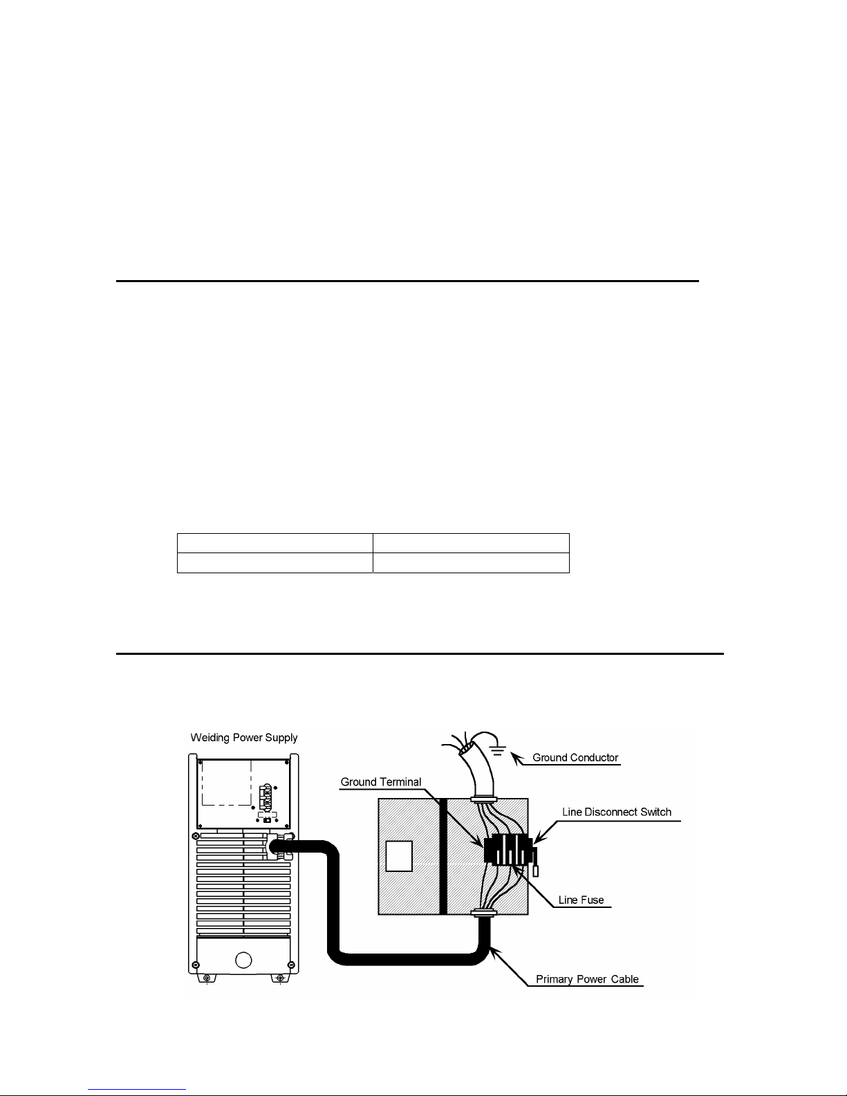
Refer to Figure 3:
1. Connect end of ground (YELLOW/GREEN) conductor to a suitable ground. Use a grounding method that
complies with all applicable electrical codes.
2. Connect ends of line 1 (BROWN) and line 2 (BLUE) and line 3 (RED) input conductors to a de-energized line
disconnect switch.
3. Use Table 1 and Table 2 as a guide to select line fuses for the disconnect switch.
Input Voltage Fuse Size
400 VAC 50 Amps
Table 1 – Electrical Input Connections
Note
Fuse size is based on not more than 200 percent of the rated input amperage of the welding power
source (Based on Article 630, National Electrical Code).
Figure 3. Electrical Input Connections
16
Page 23
3.05 Input Power
Each unit incorporates an INRUSH circuit and input voltage sensing circuit. When the MAIN SWITCH is turned
ON, the inrush circuit provides a pre-charging of the input capacitors. SCR’s in the Power Control Assembly
(PCA) will turn ON after the input capacitors have charged to full operating voltage (after approximately 5
seconds).
Note
Note the available input power. Damage to the PCA could occur if 460VAC or higher is applied.
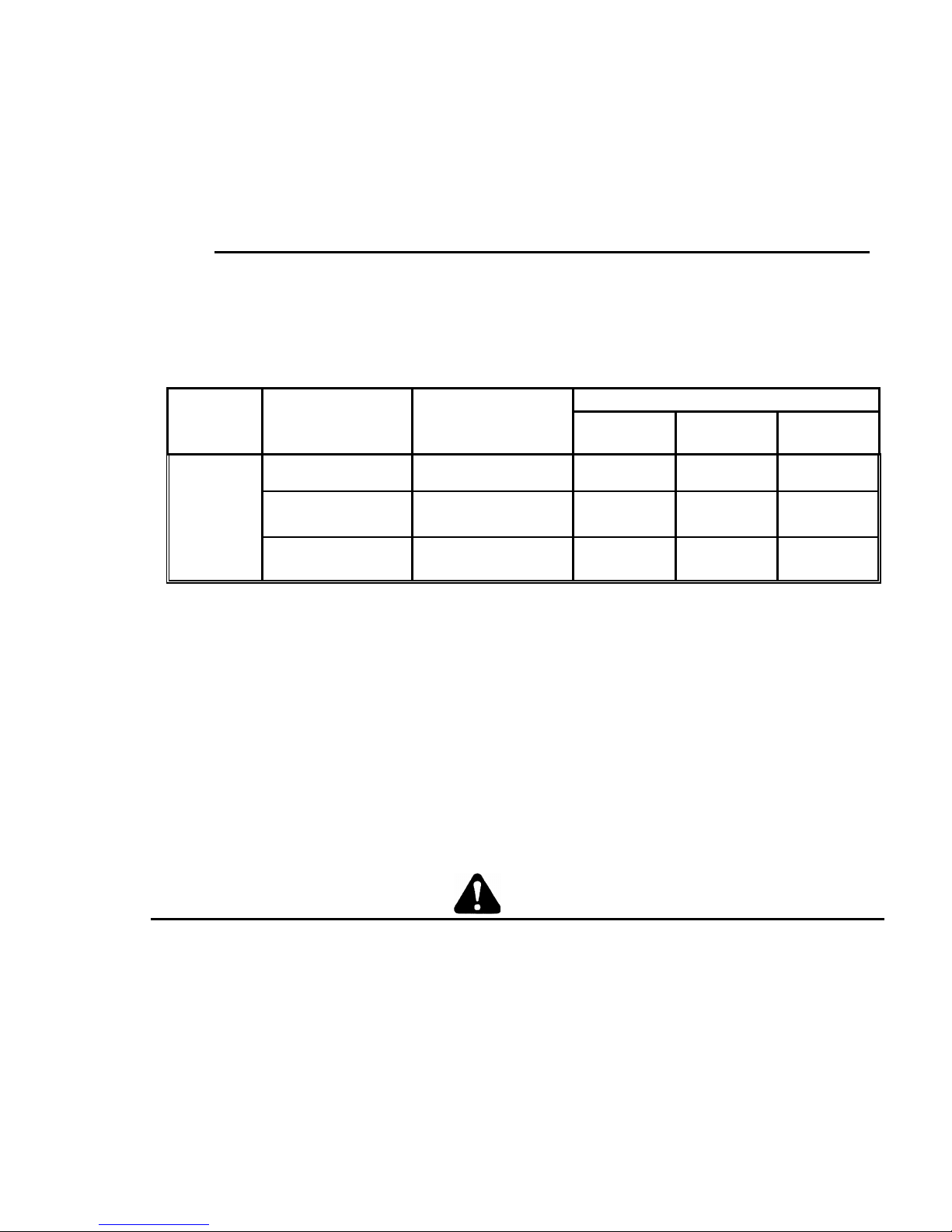
The following 208-230/460V Primary Current recommendations are required to obtain the maximum
welding current and duty cycle from this welding equipment:
Current & Duty Cycle
MIG TIG STICK
Model
Primary Supply
Lead Size
(Factory Fitted)
Minimum Primary
Current Circuit Size
(Vin/Amps)
400/33 400A @ 25% - -
ArcMaster
400 MST
4 mm sq / 4
minimum
Table 2 – Primary Current Circuit sizes to achieve maximum current
400/26 - 400A @ 25% -
400/35 - - 400A @ 25%
The ARC MASTER 400MST is designed for use with a generator as an input power source. Contact an
accredited Thermal Arc service agent for the proper sizing and set-up recommendations of a generator power
source system. As a general rule, depending on the type of generator used, the generator capacity should be
twice the maximum rating of the welder.
3.06 High Frequency Introduction
The importance of correct installation of high frequency welding equipment cannot be over-emphasized.
Interference due to high frequency initiated or stabilized arc is almost invariably traced to improper installation.
The following information is intended as a guide for personnel installing high frequency welding machines.
WARNING
Explosives
The high frequency section of this machine has an output similar to a radio transmitter. The machine
should NOT be used in the vicinity of blasting operations due to the danger of premature firing.
Computers
It is also possible that operation close to computer installations may cause computer malfunction.
17
Page 24

3.07 High Frequency Interference
Interference may be transmitted by a high frequency initiated or stabilized arc-welding machine in the following
ways:
Direct Radiation
Radiation from the machine can occur if the case is metal and is not properly grounded. It can occur
through apertures such as open access panels. The shielding of the high frequency unit in the Power
Source will prevent direct radiation if the equipment is properly grounded.
Transmission via the Supply Lead
Without adequate shielding and filtering, high frequency energy may be fed to the wiring within the
installation (mains) by direct coupling. The energy is then transmitted by both radiation and conduction.
Adequate shielding and filtering is provided in the Power Source.
Radiation from Welding Leads
Radiated interference from welding leads, although pronounced in the vicinity of the leads, diminishes
rapidly with distance. Keeping leads as short as possible will minimize this type of interference.
Looping and suspending of leads should be avoided where possible.
Re-radiation from Unearthed Metallic Objects
A major factor contributing to interference is re-radiation from unearthed metallic objects close to the
welding leads. Effective grounding of such objects will prevent re-radiation in most cases.
3.08 Duty Cycle
The duty cycle of a welding power source is the percentage of a ten (10) minute period that it can be operated at
a given output without causing overheating and damage to the unit. If the welding amperes decrease, the duty
cycle increases. If the welding amperes are increased beyond the rated output, the duty cycle will decrease.
WARNING
Exceeding the duty cycle ratings will cause the thermal overload protection circuit to become
energized and shut down the output until the unit has cooled to normal operating temperature.
CAUTION
Continually exceeding the duty cycle ratings can cause damage to the welding power source and
will void the manufactures warranty.
NOTE
Due to variations that can occur in manufactured products, claimed performance, voltages, ratings,
all capacities, measurements, dimensions and weights quoted are approximate only. Achievable
capacities and ratings in use and operation will depend upon correct installation, use, applications,
maintenance and service.
18
Page 25

3.09 Specifications
Parameter 400 MST
Rated Output
Amperes
Volts
Duty Cycle
Duty Cycle TIG
STICK
MIG
400
36
25%
400A/ 26V@ 25%
300A/ 22V @ 60%
200A/ 18V @ 100%
400A / 36V @ 25%
300A / 32V @ 60%
200A / 28V @ 100%
400A / 34V @ 25%
300A / 29V @ 60%
200A / 24V @ 100%
Output Current
Range
Output Voltage
Range
Open Circuit Voltage 65V
Dimensions
Width
Height
Length
Weight 55.1lb. 25kg
Output @ Rated Load
Output Amperes
Output Volts
Duty Cycle
KVA
KW
Output @ No Load
KVA
KW
Input Volts Three Phase
400V
Thermal Arc continuously strives to produce the best product possible and therefore reserves the right to
change, improve or revise the specifications or design of this or any product without prior notice. Such updates
or changes do not entitle the buyer of equipment previously sold or shipped to the corresponding changes,
updates, improvements or replacement of such items.
TIG
STICK
MIG 5 – 36V
5 – 400A
8.27” (210mm)
16.89” (420mm)
17.72” (450mm)
Three Phase
400A
36V
25%
24.0
18.0
0.5
0.13
Amperage Draw @ Rated Load
35
No Load
0.7
19
Page 26
SECTION 4: OPERATOR CONTROLS
4.01 ARC MASTER 400 MST Controls
6
1
8
7
9
2
10
3
4
5
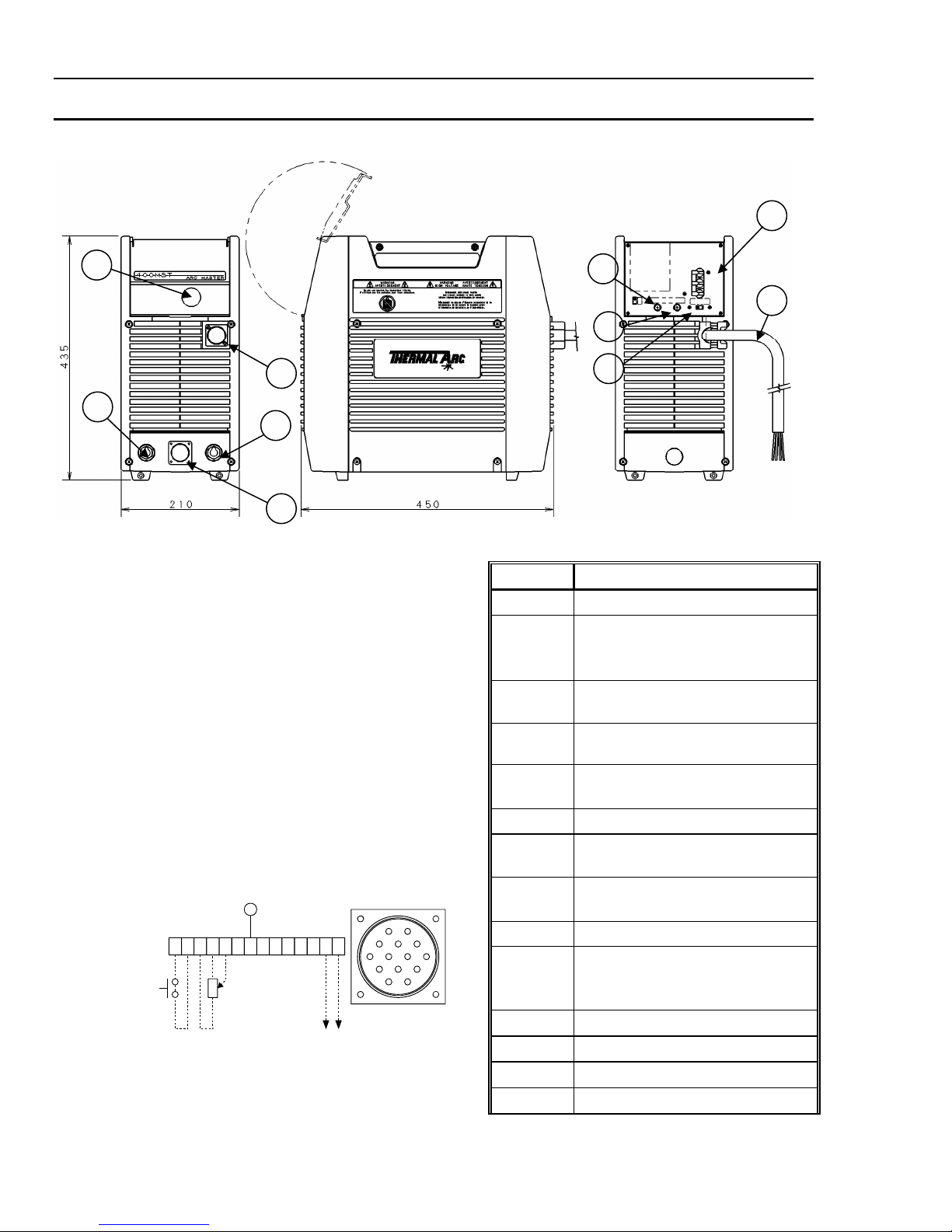
Figure 4. ARC MASTER 400 MST Power Source
1.
Control Knob
This control sets the selected weld
parameter, rotating it clockwise increases
the parameter and is indicated on the digital
meter. Pushing the knob in previews the
actual welding voltage while welding.
2. Remote Control Socket
The 14 pin Remote Control Socket is used
to connect remote current control devices to
the welding Power Source. To make
connections, align keyway, insert plug, and
rotate threaded collar fully clockwise.
E
ABCDEFGHIJKLMN
5k ohms
AJ
BKI
CLNH
DMG
FE
Front view of 14
Socket Receptacle
Socket Pin Function
A
B Input to energize solid state contactor
C 5k ohm (maximum) connection to 5k
D
E Wiper arm connection to 5k ohm
F Current feedback Ifb = 100Amps/Volt
G 24/115 VAC circuit common, also
H Voltage Feedback Vfb = 10 Arc
I 115 VAC auxiliary high side
J 115 VAC input to energize solid state
K Chassis ground
L Not Used
M Current Detect
N Current Detect
24VAC auxiliary high side.
(Contact closure between pin A and
pin B)
ohm remote control potentiometer
Zero ohm (minimum) connection to
5k ohm remote control potentiometer
remote control potentiometer
connected to chassis
Volts/Volt
contactor (Contact closure between
pin 1 and pin J)
20
Page 27

3.
Positive Terminal
Welding current flows from the Power Source via heavy duty Dinse type terminal. It is essential, however, that the
male plug is inserted and turned securely to achieve a sound electrical connection.
4.
Negative Terminal
Welding current flows from the Power Source via heavy duty Dinse type terminal. It is essential, however, that the
male plug is inserted and turned securely to achieve a sound electrical connection.
CAUTION
Loose welding terminal connections can cause overheating and result in the male plug being fused in the
bayonet terminal and /or melting of the housing (case).
5.
Remote Control Socket
The 19 pin Remote Control Socket is used to connect remote current control devices to the welding Power Source.
To make connections, align keyway, insert plug, and rotate threaded collar fully clockwise.
Socket Pin Function
A
B Contactor circuit in, (closure between pin A and Pin B will energize output.)
C Scaled output voltage signal: Vfb = 10 Arc Volts/Volt
D
E 115 VAC auxiliary power high side
G Chassis ground
H Remote control maximum
J Remote control wiper (0 – 10 Volts)
K Remote Control minimum
J Remote control wiper (0 – 10 Volts)
L Control circuit common
M Arc Establish = +12 Volts
N Control Circuit common
P 24 VAC auxiliary power high side
R 24/115 VAC neutral
S N/C
T N/C
U Scaled output signal: Ifb = 100 Amps/Volt
V N/C
Contactor circuit (+15 Volts)
24 VAC auxiliary power high side
21
Page 28

6. ON/OFF Switch
This switch connects the Primary supply voltage to the inverter when in the ON position. This enables
the Power Supply.
WARNING 5
When the welder is connected to the Primary supply voltage, the internal electrical components
may be at 500V potential with respect to earth.
7.
Input Cable
The input cable connects the Primary supply voltage to the equipment.
14/19 Pin Remote Control Select Switch
8.
User selectable switch.
Position this switch for the remote control device socket to be utilized. The unselected Remote Control
Socket is disabled at this time and cannot be utilized. Do not alter the position of this switch while one
of the Remote Control Sockets is being utilized.
9.
24VAC Remote Device C/B
Push to reset. Controls the 24VAC power source for the wire feeders controlled through the Remote
Control Sockets.
115VAC Remote Device C/B
10.
Push to reset. Controls the 115VAC power source for the wire feeders controlled through the Remote
Control Sockets.
22
Page 29
4.02 Weld Parameter Descriptions for ARC MASTER 400 MST
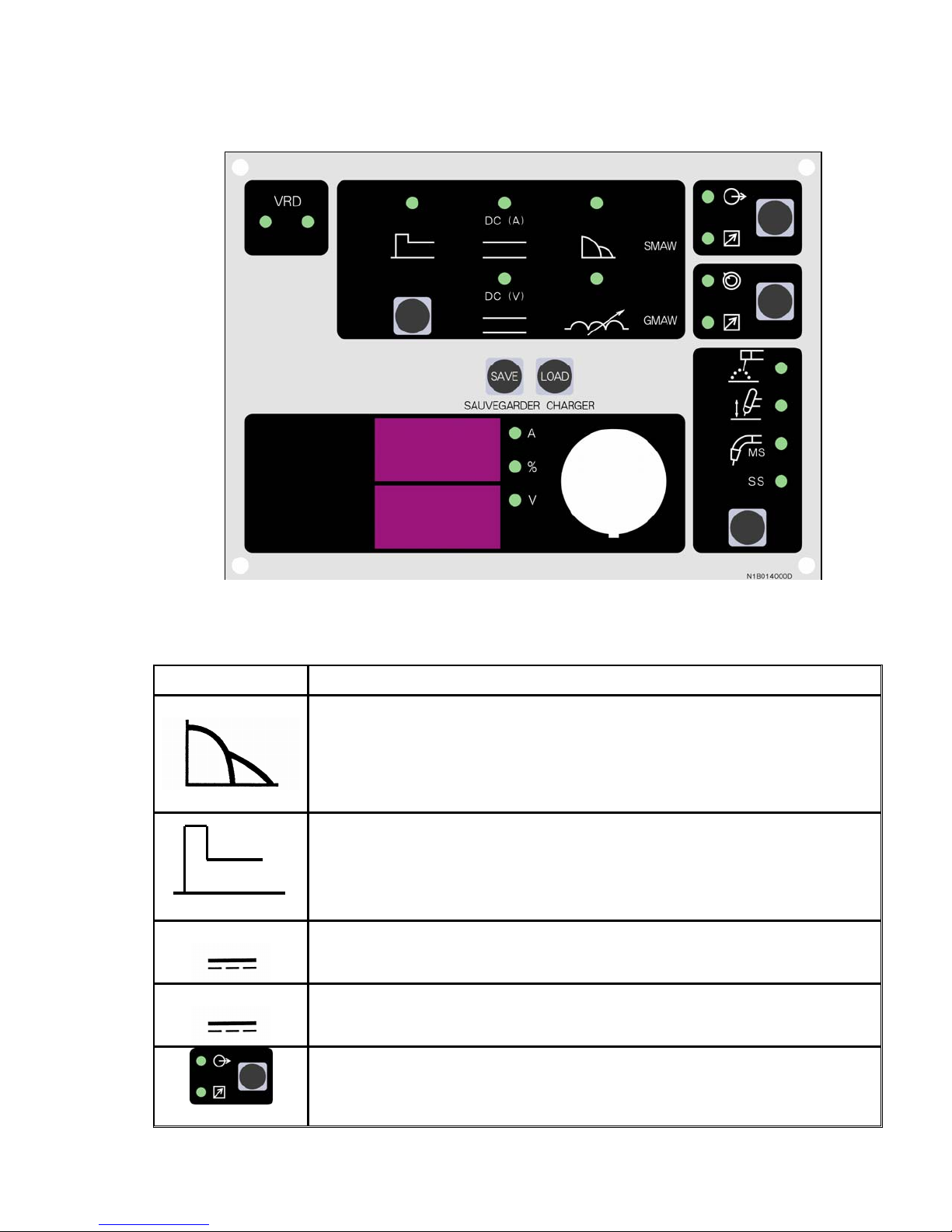
Figure 5. ARC MASTER 400 MST Front Panel with Parameter Description
Parameter Description
This parameter provides a suitable short circuit current in STICK welding to
improve electrode sticking and arc stability.
ARC CONTROL
This parameter operates in STICK weld mode and is used to improve the start
characteristics for stick electrodes. e.g. low hydrogen electrodes. It sets the peak
start current on top of the
(WELD)
current.
HOT START
DC (A)
Weld Current (Amperage) - when lit parameter knob sets the STICK and TIG
WELD current.
DC (V)
Weld Voltage (Volt) – when lit parameter knob sets the MIG voltage.
Contactor operation in Stick Mode.
Contactor ON/OFF
23
Page 30
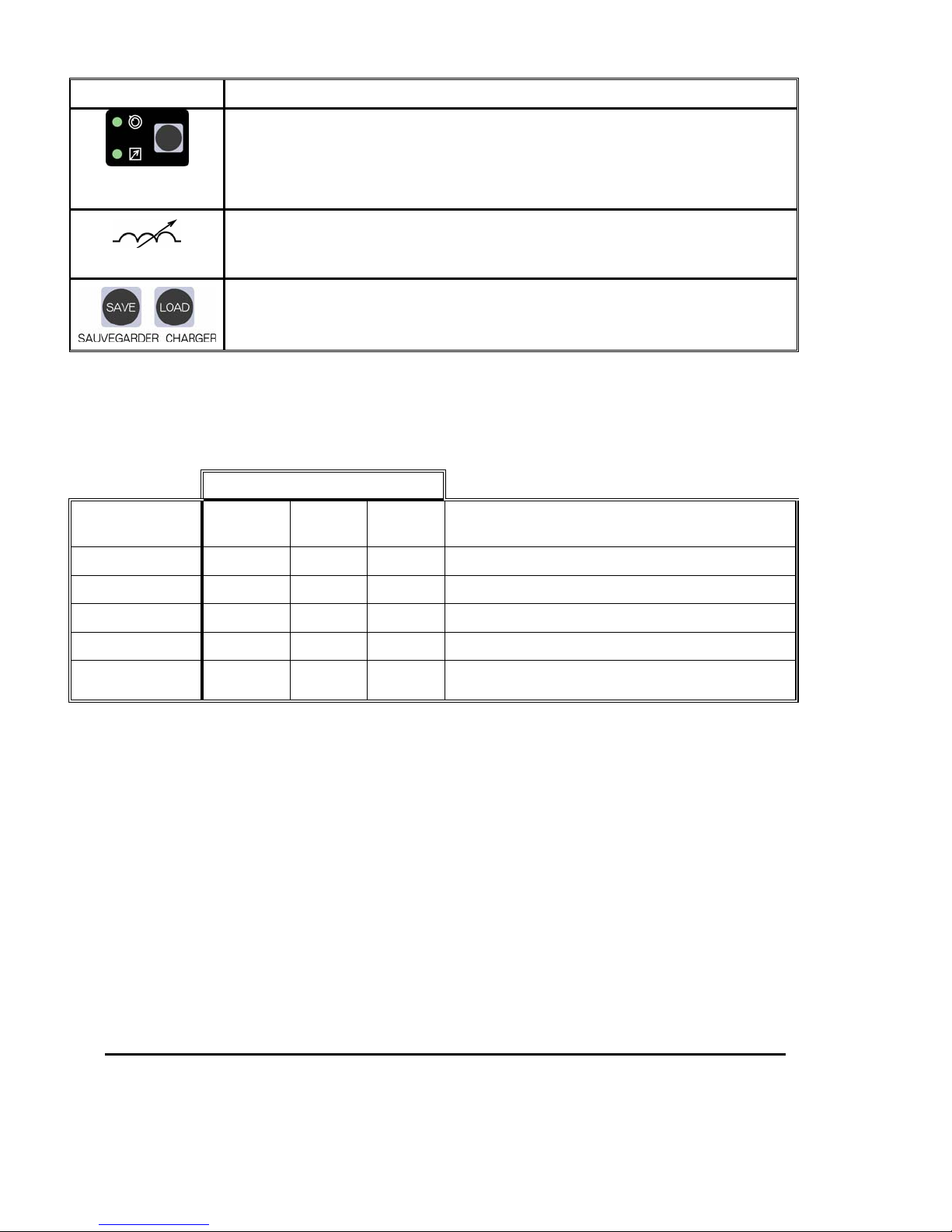
Parameter Description
Selects in operation Panel board or Remote.
Operation
PANEL/REMOTE
This parameter, similar to the ARC CONTROL in STICK mode, allows for the
INDUCTANCE
adjustment of the dynamic property of the arc. As the inductance is increased the
output voltage may need to be adjusted to achieve the desired weld characteristics.
The SAVE/LOAD buttons are used to save and retrieve a total number of 5 programs
into the 400 MST memory.
Table 3 – Weld Parameter Descriptions for ARC MASTER 400 MST
4.03 Weld Process Selection for the ARC MASTER 400 MST
Weld Mode
Weld Parameter
STICK
WELD (V)
INDUCTANCE
HOT START
WELD (A)
ARC CONTROL
Table 4 – Weld Process Selection for the ARC MASTER 400 MST
4.04 Weld Parameter Descriptions
WELD (V)
This parameter sets the MIG weld arc voltage in MIG mode.
INDUCTANCE
This parameter sets the INDUCTANCE when MIG welding. It controls the dynamic properties of the arc
in dip transfer welding mode. When this parameter is set to 0%, i.e. minimum inductance, the arc has
a fast response with a resulting crisp arc noise and coarse spatter. When this parameter is set to
100%, i.e. maximum inductance, the arc has a slow response with a resulting soft arc and fine spatter.
MIG
LIFT
TIG
Description
Weld voltage MIG Mode.
Inductance control in MIG Mode.
Start current in amps is added to the WELD (A).
WELD (A) current for STICK or LIFT TIG.
Adjusts percentage increase in welding current and is
proportional to arc length (arc voltage).
As the INDUCTANCE is increased, the WELD (V) may need to be adjusted to achieve the desired
weld characteristic.
NOTE
24
Page 31

HOT START
This parameter operates in STICK mode and improves the start characteristics for stick electrodes. e.g.
low hydrogen electrodes. It sets the peak start current on top of the WELD current.
e.g. HOT START current = 150 amps when Weld Current = 100 amps & HOT START = 50A
WELD (A)
This parameter sets the STICK & Lift TIG weld current.
ARC CONTROL
This parameter operates in STICK mode only and is used to adjust percentage increase in welding
current and is proportional to arc length (arc voltage). This control provides an adjustable amount of
arc control (or dig). This feature can be particularly beneficial in providing the operator with the ability
to compensate for variability in joint fit up in certain situations with particular electrodes, e.g. cellulose
and hydrogen controlled electrodes. In all welding processes, the amount of penetration obtained is
dependent on the welding current; i.e. the greater the penetration, the greater the current.
Arc Force Position
Current Increase when Arc
Effect on Welding Performance
Voltage is less than 18V
Minimum (0) 0A Soft arc, Low spatter, Low
penetration
Medium (20%) 32A Normal arc, Improved fusion
characteristics,
Normal penetration
Maximum (100%) 160A Hard arc, Deep penetration
Table 5 – Weld Parameter Descriptions
In general, having the ARC CONTROL set at 100% (maximum) allows greater penetration control to
be achieved. With the ARC CONTROL set at 0% (minimum) the Power Source has a constant current
characteristic. In other words, varying the arc length does not significantly affect the welding current.
When the ARC CONTROL set to 100%, it is possible to control the welding current by varying the arc
length. This is very useful for controlling penetration on root runs and side wall wash on vertical up
fillet welds.
Root runs
During root runs the weld pool forms a “keyhole” shape. If too much weld current is
used, the hole blows out and the weld collapses. If too little weld current is used, the
hole closes up and penetration is lost. The size of the hole also determines the arc
length; i.e. as the hole gets bigger, the arc gets longer.
If arc force is used, the increase in the arc length causes the weld current to decrease
until the hole starts to close up but if the hole closes up to much then the arc length
decreases which causes the weld current to increase. Too little or too much arc force
makes this process unstable. The operator must adjust the arc force until a happy
medium is reached.
25
Page 32
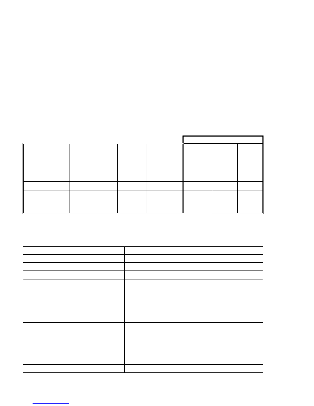
Vertical up welding
The arc force allows the weld pool to freeze during the “flick” phase without decreasing the amount of
weld current available during the “dig” phase thus maximizing penetration.
4.05 Weld Parameters
Weld Mode
Weld
Parameter
WELD (V)
MIG
INDUCTANCE
HOT START
WELD (A)
TIG or STICK
ARC CONTROL
When welding vertical up with arc force on, the operator can control the amount of
current by changing arc length, i.e. voltage. Weld metal is deposited by “digging” the
electrode into the side of the base metal joint and then increasing the arc length with a
flicking motion, to allow the weld pool to freeze, before digging the electrode into the
other side of the base metal joint.
Without arc force, increasing the arc length does not decrease the weld current
sufficiently and the operator has to manually decrease the current via a remote current
control to freeze the weld pool. This welding current reduction also reduces
the penetration.
Parameter Range Factory
Setting
10.0 to 36.0V DC 17.0V 0.1V
0 to 100% 10% 1%
0 to 70A 20A 1A
5 to 400A DC 80A 1A
0 to 100% 10% 1%
Incremental
Unit
STICK
MIG
LIFT
TIG
Table 6 – Weld Parameters
4.06 Power Source Features
Feature Description
New Digital Control
Touch Panel Switches
Front Control Cover
Digital Meter Volt & Ammeter
Intelligent Fan Control
ON/OFF Switch
• All welding parameters are adjustable
• Touch switches eliminate mechanical damage
• Protects front panel controls
• Displays selected weld parameter value
• Displays average weld current when welding
• Displays average weld current for 20 seconds after weld has
been completed
• A selected weld parameter value can be adjusted at any time
even while welding
• The intelligent cooling system is designed to reduce dust and
foreign material build-up, while providing optimum cooling.
• Fan speed reduces approximately 30 seconds after machine is
turned on
• Fan speed increases when internal components reaches
operating temperature
• Primary voltage Supply ON/OFF switch located on rear panel
26
Page 33

Feature Description
Voltage Reduction Device (VRD)
(shipped activated, field-capable)
See Section 11 for de-activation
instructions.
Control Knob
Self Diagnosis Using Error Codes
Reduces the OCV when the power supply is not in use.
Eliminates the need for add on voltage reducers and has
no effect on arc starting.
• VRD fully complies to IEC 60974-1
• When Stick mode is selected the green VRD light is
ON when not welding and red when welding.
• When in TIG modes VRD is OFF.
• For the selected weld parameter, rotating the knob
clockwise increases the parameter.
• Rotating the knob counter-clockwise decreases the
parameter.
• A selected weld parameter value can be adjusted at any
time even while welding.
• Pushing the knob in sets the selected parameter then
displays the next parameter.
• An error code is displayed on the Digital Meter when a
problem occurs with Mains supply voltage or internal
component problems.
Save/Load Function
• A total number of 5 programs can be saved into the
200AC/DC memory.
SAVE
the Current Weld Parameters into Memory
SAVE
• Press and HOLD the
button. Beep will sound
and Digital Meter display will show a number 1.
• Select a memory location by rotating the control knob,
1 to 5 is displayed on the meter.
After selecting the desired memory location (i.e. 1 to 5),
press the right scroll button and the machine will give a
beep to confirm the weld parameters are loaded onto the
control panel.
LOAD
(retrieve) a Program to Control Panel
• Press and HOLD the
LOAD
button. Beep will sound and
Digital Meter display will show a number 1.
• Select a memory location by rotating the control knob,
1 to 5 is displayed on the meter.
After selecting the desired memory location (i.e. 1 to 5),
press the right scroll button and the machine will give a
beep to confirm the weld parameters are loaded onto the
control panel.
27
Page 34
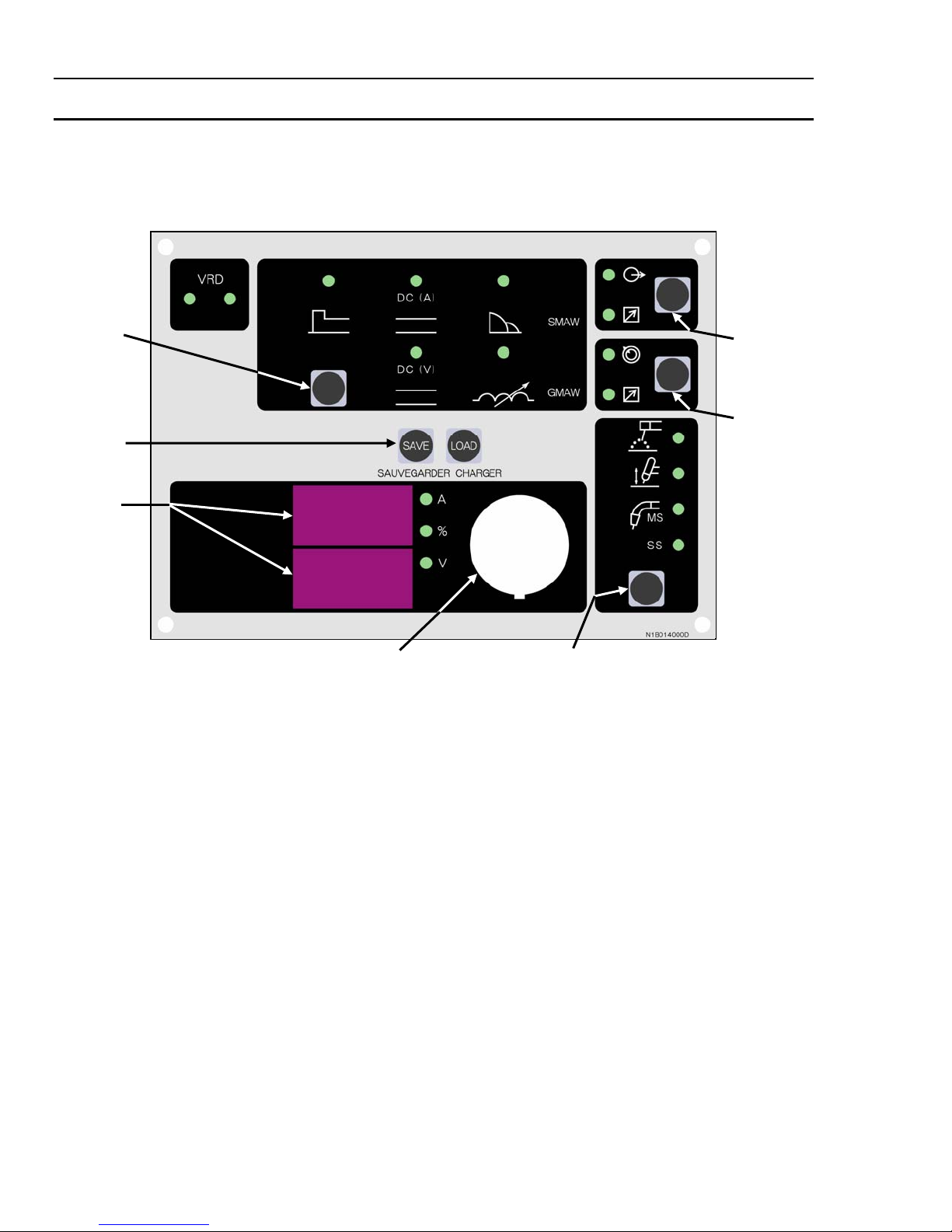
SECTION 5: SEQUENCE OF OPERATION
NOTE: Parameter Buttons are used to select the parameters to be set. The LED’s
show which function is being adjusted on the weld sequence graph. Refer to
Symbols Table located in the front of the manual for Symbol descriptions.
7
1
2
4
3
Figure 6. 400 MST Front Panel
1. Contactor Function: Pressing this buttons enables Contactor functions.
2. Remote Functions: Pressing this buttons enables remote current functions.
3. Digital LED Displays: Welding amperage, Voltage and parameter values are displayed in this window.
Internal warnings such as over temperature, low or high input voltage applied are signaled to the operator
by a warning sound and error message on the screen.
4. Save/Load Buttons: By using the Save & Load buttons the operator can easily save up to 5 welding
parameter programs.
5. Control Knob: Allows the operator to adjust the output amperage/voltage within the entire range of the
power source, also used to set each parameter value.
6. Process Button: This button selects between STICK, Lift TIG, and MIG modes. MIG modes include MS for
mild steel and SS for stainless steel.
7. Parameter Button: This button select between HOT START, WELD CURRENT, and ARC CONTROL while in
STICK and Lift TIG modes and selects between WELD VOLTAGE and INDUCTANCE CONTROL while in MIG
mode. This button is also used in conjunction with the Save/Load buttons to save and load welding
programs.
5
6
28
Page 35

5.01 Stick Welding
• Connect work lead to negative terminal
• Connect electrode lead to positive terminal
• Switch machine on
• Set weld current
• Set Contactor
• Connect remote control device if required
Use the Scroll Buttons to move to the parameter to be set. The LED will show which function is being
adjusted on the weld sequence graph. Use the control knob to adjust each parameter.
• Set
• Set
• Set
Commence welding
HOT START
ARC CONTROL
WELD
current
5.02 LIFT TIG Welding
• Connect work lead to positive terminal
• Connect TIG torch to negative terminal
• Switch machine on
• Set weld current
• Connect remote control device if required
Use the Scroll Buttons to move to the parameter to be set. The LED will show which function is being
adjusted on the weld sequence graph. Use the control knob to adjust each parameter.
Commence welding
29
Page 36

5.03 MIG Welding
• Connect work lead to negative terminal
• Connect electrode lead to positive terminal
• Switch machine on
• Set weld voltage
• Set Inductance
• Connect Wire feeder
• Set wire feed speed (IPM)
Use the Scroll Buttons to move to the parameter to be set. The LED will show which function is being
adjusted on the weld sequence graph. Use the control knob to adjust each parameter.
Commence welding
5.04 Save-Load Operation
A total number of 5 programs can be saved into the 400 MST memory.
SAVE
the Current Weld Parameters into Memory
• Press and HOLD the
• Select a memory location by rotating the control knob, 1 to 5 is displayed on the meter.
• After selecting the desired memory location (i.e. 1 to 5), press the right scroll button and the
machine will give a beep to confirm the weld parameters from the control panel are saved.
LOAD
(retrieve) a Program to Control Panel
• Press and HOLD the
• Select a memory location by rotating the control knob, 1 to 5 is displayed on the meter.
• After selecting the desired memory location (i.e. 1 to 5), press the right scroll button and the
machine will give a beep to confirm the weld parameters are loaded onto the control panel.
SAVE
button. Beep will sound and Digital Meter display will show a number 1.
LOAD
button. Beep will sound and Digital Meter display will show a number 1.
30
Page 37

SECTION 6: BASIC TIG WELDING GUIDE
6.01 Electrode Polarity
Connect the TIG torch to the - /
straight polarity. Direct current straight polarity is the most widely used polarity for DC TIG welding. It allows
limited wear of the electrode since 70% of the heat is concentrated at the work piece.
6.02 Tungsten Electrode Current Ranges
Electrode Diameter AC Current (Amps) DC Current (Amps)
0.040” (1.0mm) 30 – 70 30 – 60
1/16” (1.6mm) 60 – 95 60 – 115
3/32” (2.4mm) 125 – 150 100 – 165
1/8” (3.2mm) 130 – 225 135 – 200
5/32” (4.0mm) 190 – 280 190 – 280
TORCH
terminal and the work lead to the
+ / WORK
terminal for direct current
3/16” (4.8mm) 250 – 340 250 – 340
Table 7 – Current Ranges for Varies Tungsten Electrode Sizes
6.03 Tungsten Electrode Types
Electrode Type
(Ground Finish)
Thoriated 2%
Zirconated 1%
Ceriated 2%
Welding Application Features
DC welding of mild steel,
stainless steel and copper.
High quality AC welding of
aluminium, magnesium and
their alloys.
AC & DC welding of mild steel,
stainless steel, copper,
aluminium, magnesium and
their alloys
Excellent arc starting, Long life,
High current carrying capacity.
Self cleaning, Long life,
Maintains balled end, High
current carrying capacity.
Longer life, More stable arc,
Easier starting, Wider current
range, Narrower more
concentrated arc.
Color
Code
Red
White
Grey
Table 8 – Tungsten Electrode Types
31
Page 38
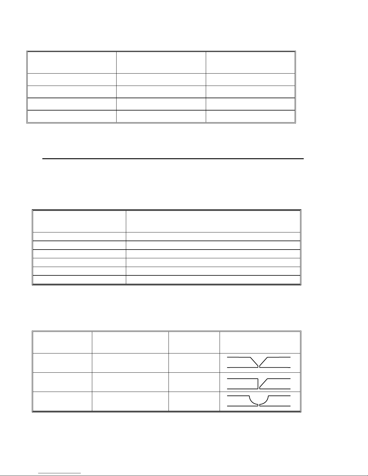
6.04 Guide for Selecting Filler Wire Diameter
Filler Wire Diameter
1/16” (1.6 mm) 30 - 95 20 - 90
3/32” (2.4 mm) 125 - 160 65 - 115
1/8” (3.2 mm) 180 - 240 100 - 165
3/16” (4.8 mm) 220 - 320 200 - 350
The filler wire diameter specified in the above table is a guide only, other diameter wires may be
used according to the welding application.
6.05 Shielding Gas Selection
Alloy
AC Current Range
(Amps)
Table 9 – Filler Wire Selection Guide
NOTE 1
Shielding Gas
Argoshield is a registered trademark of BOC Gases Limited.
DC Current Range
(Amps)
Aluminium & alloys Welding Argon, Argoshield 80T, 81T
Carbon Steel Welding Argon
Stainless Steel Welding Argon, Argoshield 71T, 80T, 81T
Nickel Alloy Welding Argon, Argoshield 71T
Copper Welding Argon, Argoshield 81T
Titanium Welding Argon, Argoshield 80T, 81T
Table 10 – Shielding Gas Selection
6.06 TIG Welding Parameters for Low Carbon & Low Alloy Steel Pipe
Electrode Type &
Diameter
Thoriated 2%
3/32” (2.4 mm)
Thoriated 2%
3/32” (2.4 mm)
Thoriated 2%
3/32” (2.4 mm)
Current Range DC
Amperes
120 - 170 Yes
100 - 160 Yes
90 - 130 No
Filler Rod for
Root Pass
Joint Preparation
Table 11 – TIG Welding Parameters for Low Carbon & Low Alloy Steel Pipe
32
Page 39

6.07 Welding Parameters for Steel
Base Metal
Thickness
0.040”
1.0mm
0.045”
1.2mm
1/16”
1.6mm
1/8”
3.2mm
3/16”
4.8mm
¼”
6.4mm
DC Current for
Mild Steel
35-45 20-30 Butt/Corner
40-50 25-35
45-55 30-45 Butt/Corner
50-60 35-50
60-70 40-60 Butt/Corner
70-90 50-70
80-100 65-85 Butt/Corner
90-115 90-110
115-135 100-125 Butt/Corner
140-165 125-150
160-175 135-160 Butt/Corner
170-200 160-180
DC Current for
Stainless
Steel
Tungsten
Electrode
Diameter
0.040”
1.0mm
0.040”
1.0mm
1/16”
1.6mm
1/16”
1.6mm
3/32”
2.4mm
1/8”
3.2mm
Filler Rod
Diameter
(if required)
1/16”
1.6mm
1/16”
1.6mm
1/16”
1.6mm
3/32”
2.4mm
1/8”
3.2mm
5/32”
4.0mm
Argon Gas
Flow Rate
Liters/min
5-7
5-7
7
7
10
10
Joint Type
Lap/ Fillet
Lap/ Fillet
Lap/ Fillet
Lap/ Fillet
Lap/ Fillet
Lap/ Fillet
Table 12 – DC TIG Welding Parameters
33
Page 40

SECTION 7: BASIC STICK WELDING GUIDE
7.01 Electrode Polarity
Stick electrodes are generally connected to the ‘+’ terminal and the work lead to the ‘−’ terminal but if in doubt
consult the electrode manufacturers literature.
7.02 Effects of Stick Welding Various Materials
High tensile and alloy steels
The two most prominent effects of welding these steels are the formation of a hardened zone in the weld area,
and, if suitable precautions are not taken, the occurrence in this zone of under-bead cracks. Hardened zone
and under-bead cracks in the weld area may be reduced by using the correct electrodes, preheating, using
higher current settings, using larger electrodes sizes, short runs for larger electrode deposits or tempering in
a furnace.
Manganese steels
The effect on manganese steel of slow cooling from high temperatures is to embrittle it. For this reason it is
absolutely essential to keep manganese steel cool during welding by quenching after each weld or skip
welding to distribute the heat.
Cast Iron
Most types of cast iron, except white iron, are weldable. White iron, because of its extreme brittleness,
generally cracks when attempts are made to weld it. Trouble may also be experienced when welding whiteheart malleable, due to the porosity caused by gas held in this type of iron.
Copper and alloys
The most important factor is the high rate of heat conductivity of copper, making preheating of heavy sections
necessary to give proper fusion of weld and base metal.
Types of Electrodes
Arc Welding electrodes are classified into a number of groups depending on their applications. There are a
great number of electrodes used for specialized industrial purposes which are not of particular interest for
everyday general work. These include some low hydrogen types for high tensile steel, cellulose types for
welding large diameter pipes, etc. The range of electrodes dealt with in this publication will cover the vast
majority of applications likely to be encountered; are all easy to use and all will work on even the most basic
of welding machines.
Metals being joined Electrode Comments
Mild steel 6013 Ideal electrodes for all general purpose
Mild steel 7014 All positional electrode for use on mild and
Cast iron 99% Nickel Suitable for joining all cast irons except
Stainless steel 318L-16 High corrosion resistance. Ideal for dairy
work. Features include out standing
operator appeal, easy arc starting and
low spatter.
galvanized steel furniture, plates, fences,
gates, pipes and tanks etc. Especially
suitable for vertical-down welding.
white cast iron.
work, etc. on stainless steels.
34
Page 41

Metals being joined Electrode Comments
Copper, Bronze, Brass, etc. Bronze
5.7 ERCUSI-A
High Alloy Steels,
Dissimilar Metals,
Crack Resistance.
All Hard-To-Weld Jobs.
312-16 It will weld most problematical jobs such
Easy to use electrode for marine fittings,
water taps and valves, water trough float
arms, etc. Also for joining copper to steel
and for bronze overlays on steel shafts.
as springs, shafts, broken joins mild steel
to stainless and alloy steels.
Not suitable for Aluminium.
Table 13 - Types of Electrodes
35
Page 42
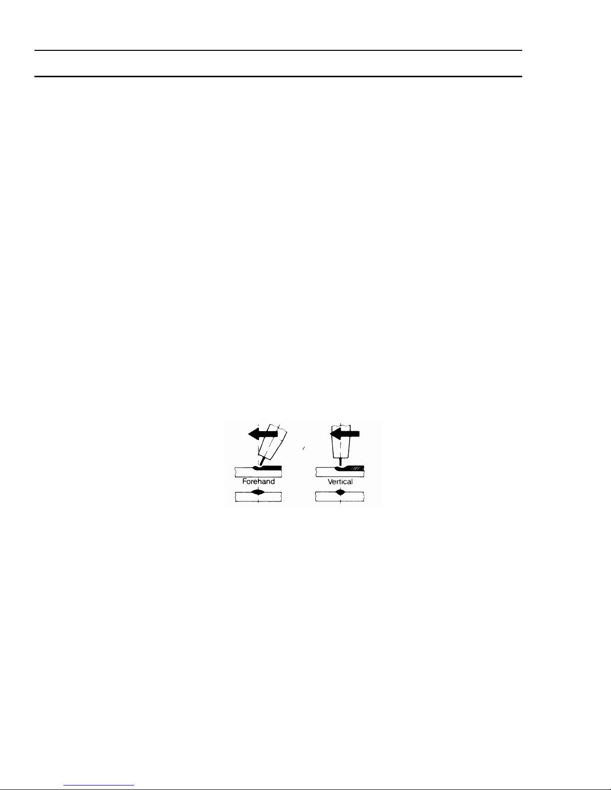
SECTION 8.0 BASIC MIG WELDING GUIDE
8.01 Setting of the Power Source
The setting of the ARC MASTER 400 MST requires some practice by the operator, the welding Power
Source/Wirefeeder having two control settings that have to balance. These are the Wirespeed control and the
Voltage Control. The welding current is determined by the Wirespeed control, the current will increase with
increased Wirespeed, resulting in a shorter arc. Less wire speed will reduce the current and lengthen the arc.
Increasing the welding voltage hardly alters the welding current level, but lengthens the arc. By decreasing
the voltage, a shorter arc is obtained with little change in welding current.
When changing to a different electrode wire diameter, different control settings are required. A thinner
electrode wire needs more Wirespeed to achieve the same current level.
A satisfactory weld cannot be obtained if the wirespeed and voltage switch settings are not adjusted to suit
the electrode wire diameter and dimensions of the workpiece.
If the Wirespeed is too high for the welding voltage, “stubbing” will occur as the wire dips into the molten
pool and does not melt. Welding in these conditions normally produces a poor weld due to lack of fusion. If,
however, the welding voltage is too high, large drops will form on the end of the electrode wire, causing
spatter. The correct setting of voltage and Wirespeed can be seen in the shape of the weld deposit and heard
by a smooth regular arc sound.
8.02 Position of MIG Torch
The angle of MIG torch to the weld has an effect on the width of the weld run.
Figure 7. MIG Torch Angle
8.03 Distance from the MIG Torch Nozzle to the Work Piece
The electrode stick out from the MIG Torch nozzle should be between ¼” to 3/8”. This distance may vary
depending on the type of joint that is being welded.
36
Page 43
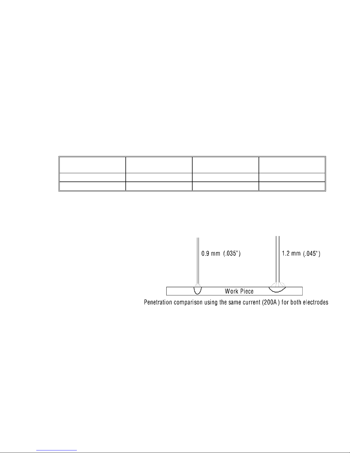
p
8.04 Travel Speed
Speed at which a weld travels influences the width of the weld and penetration of the welding run.
8.05 Electrode Wire Size Selection
The choice of electrode wire size in conjunction with shielding gas used depends on:
The position of welding Thickness of the metal to be welded
The deposition rate required Capacity of the wire feed unit and power source
The bead profile desired The amount of penetration required
Type of joint Cost of the electrode wire
Weld metal deposition rate is proportional to current density. Current density is defined as the current
per cross sectional area of the electrode wire and is normally expressed as amps per mm
is tabled below.
Electrode Wire Size
0.035” (0.9mm) 200 380 6.3
0.034” (1.2mm) 200 177 6.0
Current (Amps)
Current Density
(Amps/mm
2
)
Deposition Rate
2
. An example
(lb/hour)
8.06 Deposition Rate Comparison
This demonstrates that where the upper limit of current is limited by machine capacity and duty cycle, higher
deposition rates and therefore
greater productivity will be achieved
by using smaller electrode wire. The
ARC MASTER 400 MST is a
particularly efficient MIG welder
with the 0.9mm steel wire in spray
transfer mode. The savings from
decreased welding time will more
than cover the small cost penalty of
the smaller electrode wire sizes.
0.035” wire cost approximately 10%
more than 0.045”, but is deposited
approximately 15% faster.
Higher current density (or smaller diameter wire)
also gives deeper penetration as shown.
Wire Penetration Com
arison
37
Page 44

SECTION 9: ROUTINE MAINTENANCE
The only routine maintenance required for the power supply is a thorough cleaning and inspection, with the
frequency depending on the usage and the operating environment.
The unit should be wiped clean as necessary with solvents that are recommended for cleaning electrical
apparatus. Turn Power Switch to OFF before proceeding. Internal cleaning of the unit should be done every 6
months by an authorized Thermal Arc Service Center to remove any accumulated dirt and dust. This may need
to be done more frequently under exceptionally dirty conditions.
CAUTION
Do not blow air into the power supply during cleaning. Blowing air into the unit can cause metal
particles to interfere with sensitive electrical components and cause damage to the unit.
38
Page 45
SECTION 10: BASIC TROUBLESHOOTING
WARNING
There are extremely dangerous voltages and power levels present inside this product. Do not attempt
to open or repair unless you are an accredited Thermal Arc Service Agent and you have had training
in power measurements and troubleshooting techniques.
If major complex subassemblies are faulty, then the Welding Power Source must be returned to an accredited
Thermal Arc Service Agent for repair.
The basic level of troubleshooting is that which can be performed without special equipment or knowledge.
10.01 Solving MIG Problems beyond the Welding Terminals
The general approach to fix Gas Metal Arc Welding (GMAW) problems is to start at the wire spool then work
through to the MIG torch. There are two main areas where problems occur with GMAW:
Porosity
When there is a gas problem the result is usually porosity within the weld metal. Porosity always stems from
some contaminant within the molten weld pool which is in the process of escaping during solidification of the
molten metal.
Contaminants range from no gas around the welding arc to dirt on the work piece surface. Porosity can be
reduced by checking the following points:
1. Gas cylinder contents and flow meter.
2. Gas leaks.
3. Internal gas hose in the Wire Feeder.
4. Welding in a windy environment.
5. Welding dirty, oily, painted, oxidized or
greasy plate.
6. Distance between the MIG torch nozzle and
the work piece.
Ensure that the gas cylinder is not empty and the flow meter is
correctly adjusted to 25 cubic feet per hour.
Check for gas leaks between the regulator/cylinder connection
and in the gas hose to the Wire Feeder.
Ensure the hose from the solenoid valve to the MIG torch
adapter has not fractured and that it is connected to the MIG
torch adapter.
Shield the weld area from the wind or increase the gas flow.
Clean contaminates off the plate.
Keep the distance between the MIG torch nozzle and the work
piece to a minimum.
7. Maintain the MIG torch in good
working order.
Check that the MIG torch O-rings are not damaged.
Ensure that the gas holes are not blocked and gas is exiting out
of the torch nozzle.
Do not restrict gas flow by allowing spatter to build up inside
the MIG torch nozzle.
39
Page 46

WARNING
Disengage the drive roll when testing for gas flow by ear.
Inconsistent Wire Feed
Checking the following points can reduce wire-feeding problems:
1. Wire spool brake is too tight.
2. Wire spool brake is too loose.
3. Worn or incorrect feed roller size.
4. Misalignment of inlet/outlet guides.
5. Liner blocked with wire debris.
6. Incorrect or worn contact tip.
Feed roller driven by motor in the cabinet will slip.
Wire spool can unwind and tangle.
Use 'U' groove drive feed roller matched to the
aluminium wire size you are welding.
Use 'V' groove drive feed roller matched to the steel
wire size you are welding.
Use ‘knurled V’ groove drive feed roller matched to the
flux cored wire size you are welding.
Wire will rub against the misaligned guides and
reduces wire feedability.
Wire debris is produced by the wire passing through
the feed roller, if excessive pressure is applied to the
pressure roller adjuster.
Wire debris can also be produced by the wire passing
through an incorrect feed roller groove shape or size.
Wire debris is fed into the liner where it accumulates
thus reducing wire feedability.
The contact tip transfers the weld current to the
electrode wire. If the hole in the contact tip is to large
then arcing may occur inside the contact tip resulting
in the electrode wire jamming in the contact tip.
7. Poor work lead contact to work piece.
8. Bent liner.
When using soft electrode wire such as aluminium it
may become jammed in the contact tip due to
expansion of the wire when heated. A contact tip
designed for soft electrode wires should be used.
If the work lead has a poor electrical contact to the
work piece then the connection point will heat up and
result in a reduction of power at the arc.
This will cause friction between the wire and the liner
thus reducing wire feedability.
40
Page 47

10.02 MIG Welding Problems
Description
1 Undercut. A Welding arc voltage too high. A
B Incorrect torch angle. B Adjust angle.
C Excessive heat input. C
2 Lack of penetration. A Welding current too low. A
B
C Shielding gas incorrect. C
3 Lack of fusion. Voltage too low. Increase
4 Excessive spatter. A Voltage too high. A
B Voltage too low. B
5
Irregular weld
shape.
B Wire is wandering. B Replace contact tip.
C Incorrect shielding gas. C Check shielding gas.
D Insufficient or excessive heat input. D
6 Weld cracking. A Weld beads too small. A Decrease travel speed.
B Weld penetration narrow and deep. B
C Excessive weld stresses. C
D Excessive voltage. D
E Cooling rate too fast. E
7 Cold weld
Joint preparation too narrow or gap
too tight.
A
Incorrect voltage and current
settings. Convex, voltage too low.
Concave, voltage too high.
Faulty rectifier unit.
A
puddle.
B
C
Loose welding cable connection.
Low Primary Voltage.
Possible Cause
Remedy
Reduce
feed speed.
Increase the torch travel speed and/or reduce
welding current by reducing the
control or reducing the wire feed speed.
Increase welding current by increasing wire
feed speed and increasing
B Increase joint angle or gap.
Change to a gas which gives
higher penetration.
WELD (V)
WELD (V)
Lower the voltage by reducing the
control or increase wirespeed control.
Raise the voltage by increasing the
control or reduce wirespeed control.
A
Adjust voltage and current by adjusting the
WELD (V)
Adjust the wirespeed control or the voltage
selection switches.
Reduce current and voltage and increase MIG
torch travel speed or select a lower
penetration shielding gas.
Increase weld metal strength or
revise design.
Decrease voltage by reducing the
WELD (V)
Slow the cooling rate by preheating part to be
welded or cool slowly.
Have an accredited Thermal Arc Service Agent
A
to test then replace the faulty component.
Check all welding cable connections.
B
Contact supply authority.
C
control and the wirespeed control.
control.
control or increase the wire
WELD (V)
WELD (V)
control.
control.
WELD (V)
WELD (V)
41
Page 48

8 Arc does not
have
a crisp sound,
that short arc
exhibits, when
the wirefeed
speed
and voltage are
adjusted
correctly.
The MIG torch has been connected
to the wrong voltage polarity on the
front panel.
Connect the MIG torch to the positive (+)
welding terminal for solid wires and gas
shielded flux cored wires. Refer to the
electrode wire manufacturer for the
correct polarity.
42
Page 49

10.03 TIG Welding Problems
Weld quality is dependent on the selection of the correct consumables, maintenance of equipment and proper
welding technique.
Description
1 Excessive beard
build-up or poor
Possible Cause
Remedy
Welding current is too low. Increase weld current and/or
faulty joint preparation.
penetration or poor
fusion at edges
of weld.
2 Weld bead too wide
Welding current is too high. Decrease weld current.
and flat or undercut
at edges of weld or
excessive
burn through.
3 Weld bead too small
Travel speed too fast. Reduce travel speed.
or insufficient
penetration or
ripples in bead are
widely spaced apart.
4 Weld bead too wide
Travel speed too slow. Increase travel speed.
or excessive bead
build up or excessive
penetration in butt
joint.
5 Uneven leg length in
Wrong placement of filler rod. Re-position filler rod.
fillet joint.
6 Electrode melts
when arc is struck.
7 Dirty weld pool. A Electrode contaminated
Electrode is connected to the
‘+’ terminal.
through contact with work
Connect the electrode to the
‘−’ terminal.
A Clean the electrode by
grinding off the contaminates.
piece or filler
rod material.
B Gas contaminated with air. B Check gas lines for cuts and
loose fitting or change gas
cylinder.
43
Page 50

Description
Possible Cause
Remedy
8 Electrode melts or
oxidizes when an arc
is struck.
A No gas flowing to
welding region.
A Check the gas lines for kinks
or breaks and gas cylinder
contents.
B Torch is clogged with dust. B Clean torch.
C Gas hose is cut. C Replace gas hose.
D Gas passage contains
impurities.
D Disconnect gas hose from
torch then raise gas pressure
and blow out impurities.
E Gas regulator turned OFF. E Turn ON.
F Torch valve is turned OFF. F Turn ON.
G The electrode is too small for
the welding current.
H
WAVE BALANCE
is set above
50%.
G Increase electrode diameter or
reduce the welding current.
H Reduced
WAVE BALANCE
below 50% or increase the
electrode size.
9 Poor weld finish. Inadequate shielding gas. Increase gas flow or check
gas line for gas flow
problems.
10 Arc flutters during
TIG welding.
A Tungsten electrode is too
large for the welding current.
A Select the right size electrode.
Refer to Basic TIG Welding
guide.
B Absence of oxides in the
weld pool.
B Refer Basic TIG Welding
Guide for ways to reduce arc
flutter.
11 Welding arc cannot
be established.
A Work clamp is not connected
to the work piece or the
work/torch leads are not
connected to the right welding
A Connect the work clamp to the
work piece or connect the
work/torch leads to the right
welding terminals.
terminals.
B Torch lead is disconnected. B
C Gas flow incorrectly set,
cylinder empty or the torch
valve is OFF.
Connect it to the ‘−‘ terminal.
C Select the right flow rate,
change cylinders or turn torch
valve ON.
to
44
Page 51

Description
Possible Cause
Remedy
12 Arc start is not
smooth.
A Tungsten electrode is too
large for the welding current.
A Select the right size electrode.
Refer to Basic TIG Welding
Guide.
B The wrong electrode is being
used for the welding job.
B Select the right electrode type.
Refer to Basic TIG Welding
Guide.
C Gas flow rate is too high. C Select the correct rate for
the welding job.
Refer to Basic TIG Welding
Guide.
D Incorrect shielding gas is
being used.
D Select the right shielding gas.
Refer to Basic TIG Welding
Guide.
E Poor work clamp connection
to work piece.
E Improve connection to
work piece.
10.04 Stick Welding Problems
Description
Possible Cause
Remedy
1 Gas pockets or
voids in weld metal
(Porosity).
A
Electrodes are damp.
B
Welding current is too high.
C
Surface impurities such as oil,
A
Dry electrodes before use.
B
Reduce welding current.
C
Clean joint before welding.
grease, paint, etc.
2 Crack occurring in
weld metal soon
after solidification
commences.
3 A gap is left by
failure of the weld
metal to fill the root
of the weld.
D Incorrect sequence. D Use correct build-up sequence.
A
Rigidity of joint.
B
Insufficient throat thickness.
C
Cooling rate is too high.
A
Welding current is too low.
B
Electrode too large for joint.
C
Insufficient gap.
A
Redesign to relieve weld joint
of severe stresses or use crack
resistance electrodes.
B
Travel slightly slower to allow
greater build up in throat.
C
Preheat plate and cool slowly.
A
Increase welding current.
B
Use smaller diameter
electrode.
Allow wider gap.
C
Figure 8. Example of Insufficient Gap or Incorrect Sequence
45
Page 52
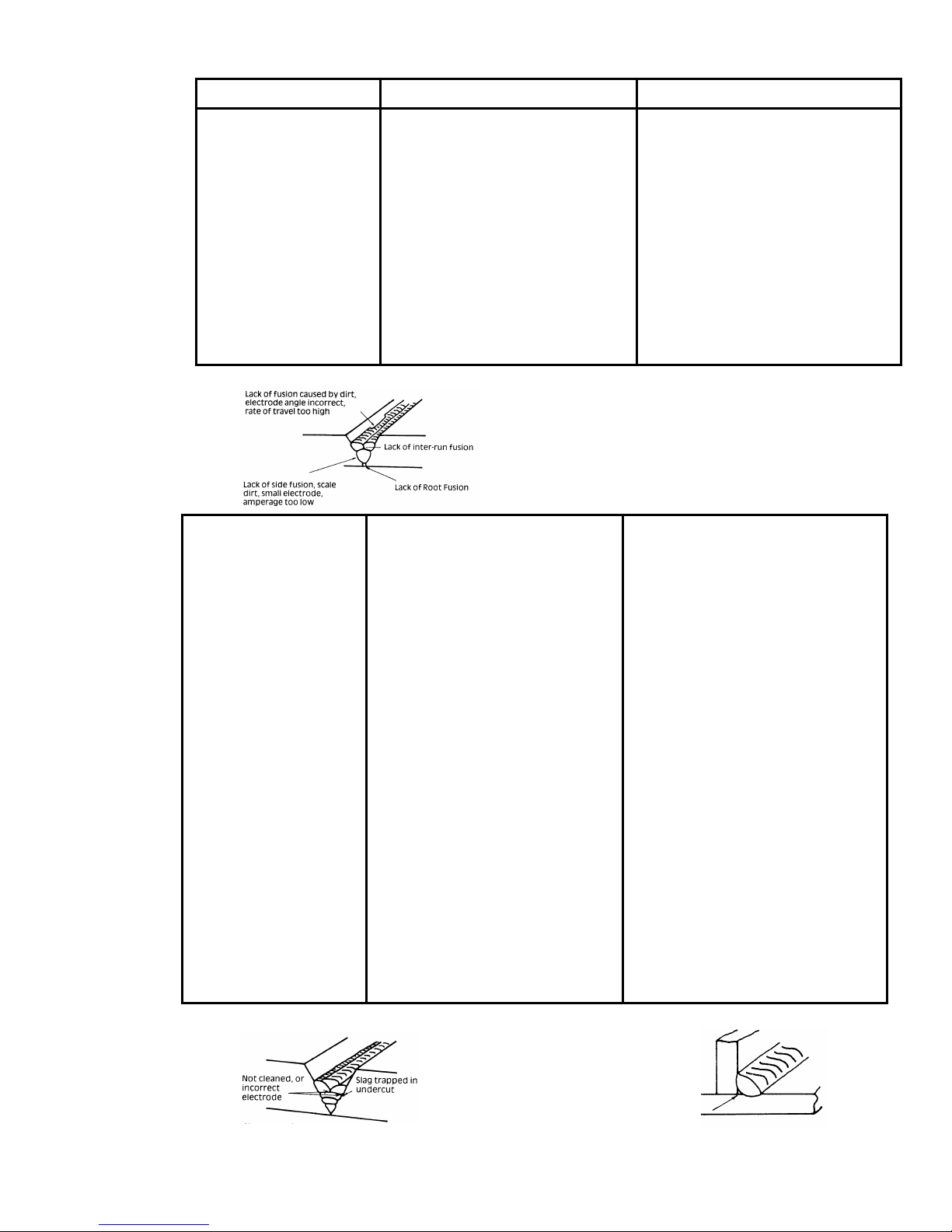
Description
Possible Cause
Remedy
4 Portions of the
weld run do not
fuse to the surface
A
Small electrodes used on
heavy cold plate.
B
Welding current is too low.
of the metal or
edge of the joint.
C Wrong electrode angle. C Adjust angle so the welding
D Travel speed of electrode is
too high.
E Scale or dirt on joint surface. E Clean surface before welding.
5 Non-metallic
particles are
trapped in the weld
A Non-metallic particles may be
trapped in undercut from
previous run.
metal (slag
inclusion).
B Joint preparation too
restricted.
C Irregular deposits allow slag
to be trapped.
D Lack of penetration with slag
trapped beneath weld bead.
E Rust or mill scale is
preventing full fusion.
F Wrong electrode for position
in which welding is done.
A
Use larger electrodes and
pre-heat the plate.
B
Increase welding current.
arc is directed more into the
base metal.
D Reduce travel speed of
electrode.
Figure 9. Example of Lack of Fusion
A If bad undercut is present,
clean slag out and cover with a
run from a smaller diameter
electrode.
B Allow for adequate penetration
and room for cleaning out the
slag.
C If very bad, chip or grind
out irregularities.
D Use smaller electrode with
sufficient current to give
adequate penetration. Use
suitable tools to remove all
slag from corners.
E Clean joint before welding.
F Use electrodes designed for
position in which welding is
done, otherwise proper control
of slag is difficult.
Figure 10. Examples of Slag Inclusion
46
Page 53

10.05 Power Source Problems
Description Possible Cause Remedy
1 The welding arc
cannot be
established.
A
The Primary supply voltage
has not been switched ON.
B
The Welding Power Source
switch
A
Switch ON the Primary
supply voltage.
B
Switch ON the Welding
Power Source.
is switched OFF.
C Loose connections internally. C Have an accredited Thermal
Arc Service Agent repair the
connection.
2 Maximum output
welding current
cannot be achieved
Defective control circuit. Have an accredited Thermal
Arc Service Agent inspect then
repair the welder.
with nominal Mains
supply voltage.
3 Welding current
reduces when
welding
4
No gas flow when
the torch trigger
switch is
depressed.
Poor work lead connection to
the work piece.
A B Gas hose is cut.
Gas passage contains
impurities.
Ensure that the work lead has a
positive electrical connection
to the work piece.
ABReplace gas hose.
Disconnect gas hose from the
rear of Power Source then raise
gas pressure and blow out
impurities.
C Gas regulator turned OFF. C Turn gas regulator ON.
D Torch trigger switch lead is
disconnected or switch/cable
Reconnect lead or repair faulty
switch/cable.
is faulty.
47
Page 54

Description Possible Cause Remedy
5
Gas flow won’t
shut OFF.
A Weld Mode (
REPEAT
STD, SLOPE
or
SPOT
changed before
gas time had finished.
,
) was
POST-FLOW
A Strike an arc to complete the
weld cycle.
OR
Switch machine OFF then ON
to
reset solenoid valve sequence.
B Gas valve is faulty. B Have an accredited Thermal
Arc Service Agent replace gas
valve.
C Gas valve jammed open. C Have an accredited Thermal
Arc Service Agent repair or
replace
gas valve.
D
POST-FLOW
control is set
D Reduce
POST-FLOW
to 60 sec.
6 The TIG electrode
has been
contaminated due
to the gas flow
shutting OFF before
The Weld Process Mode
(STICK, HF TIG or LIFT TIG)
was changed before
FLOW
gas time
had finished.
POST-
Do not change Weld Process
Mode before the
gas time had finished.
the programmed
POST-FLOW
time
has elapsed.
time.
POST-FLOW
48
Page 55

SECTION 11: VOLTAGE REDUCTION DEVICE (VRD)
11.01 VRD Specifications
Description
VRD Open Circuit Voltage 15.3 to 19.8V Open circuit voltage between welding terminals.
VRD Resistance 148 to 193 ohms The required resistance between welding terminals
VRD Turn OFF Time 0.2 to 0.3 seconds The time taken to turn OFF the welding power once
11.02 VRD Maintenance
Routine inspection and testing (power source)
An inspection of the power source, an insulation resistance test and an earth resistance test shall be
carried out.
a) For transportable equipment, at least once every 3 months.
b) For fixed equipment, at least once every 12 months.
ARC MASTER
400 MST
Notes
to turn ON the welding power.
the welding current has stopped.
The owners of the equipment shall keep a suitable record of the periodic tests.
Note
A transportable power source is any equipment that is not permanently connected and
fixed in the position in which it is operated.
In addition to the above tests and specifically in relation to the VRD fitted to this machine, the
following periodic tests should also be conducted by an accredited Thermal Arc service agent.
Description IEC 60974-1 Requirements
VRD Open Circuit Voltage Less than 20V; at Vin=400V
VRD Turn ON Resistance Less than 200 ohms
VRD Turn OFF Time Less than 0.3 seconds
If this equipment is used in a hazardous location or environments with a high risk of
electrocution then the above tests should be carried out prior to entering this location.
49
Page 56
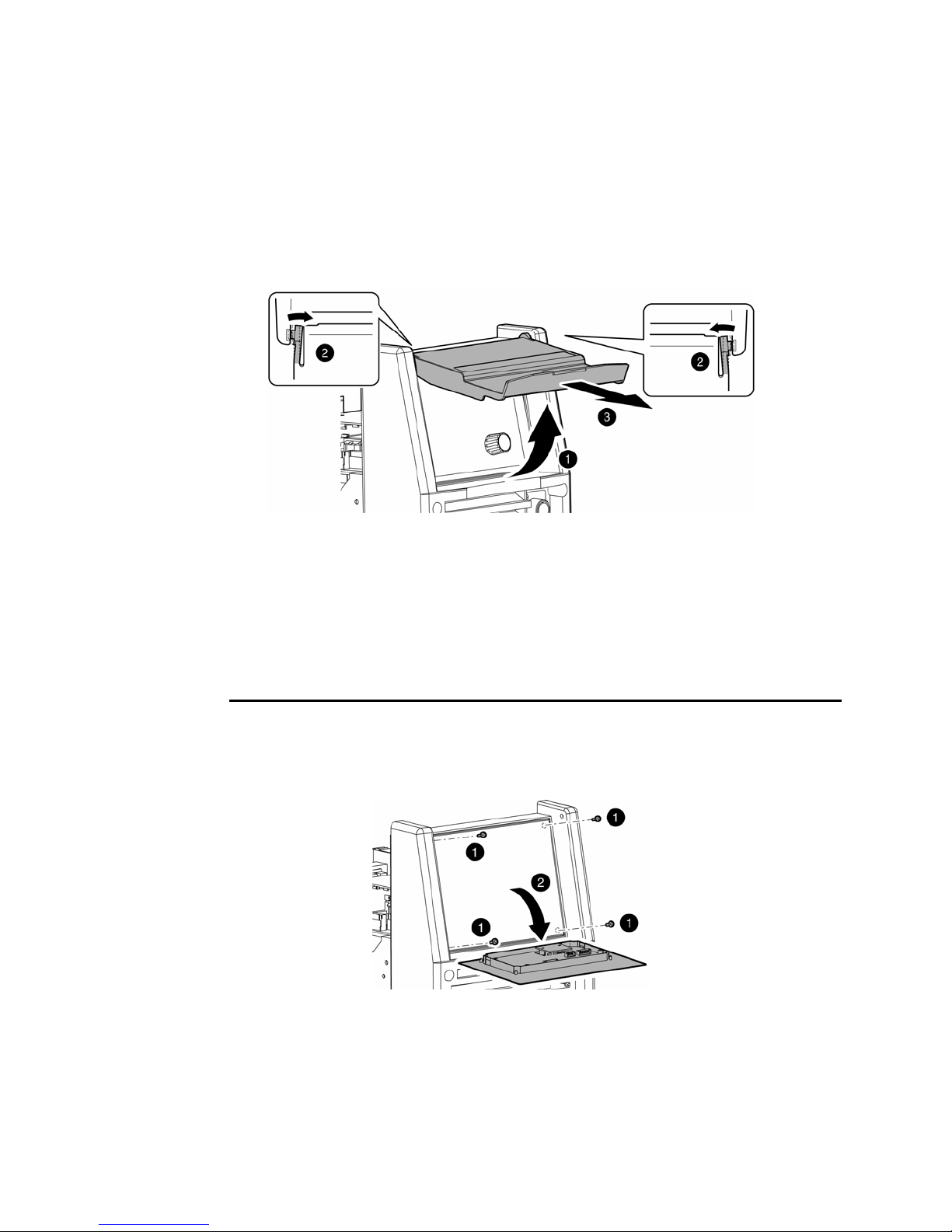
11.03 Switching VRD On/Off
Switch the machine OFF.
a) Remove the clear plastic cover from the control panel. (see Figure 11)
• Lift up the cover so it rests ON the top of the unit.
• Place a small flat bladed screw driver between the cover hinge on the front panel.
• Gently lift the cover hinge out of the front cover mounting hole.
• Remove the control’s clear plastic cover.
b) Remove four mounting screws from the control panel. (see Figure 12)
c) Access the VRD control by gently prying back the front panel controls to reveal the
VRD ON/OFF potentiometer. (see Figure 12)
Figure 11.
VRD ON/OFF Step A
CAUTION 1
Do not pull back the front panel with excessive force as this will unplug control PCB.
Plugging the control PCB back into the front panel controls can only be achieved by removing
the side covers.
Figure 12.
VRD ON/OFF Step B,C
50
Page 57
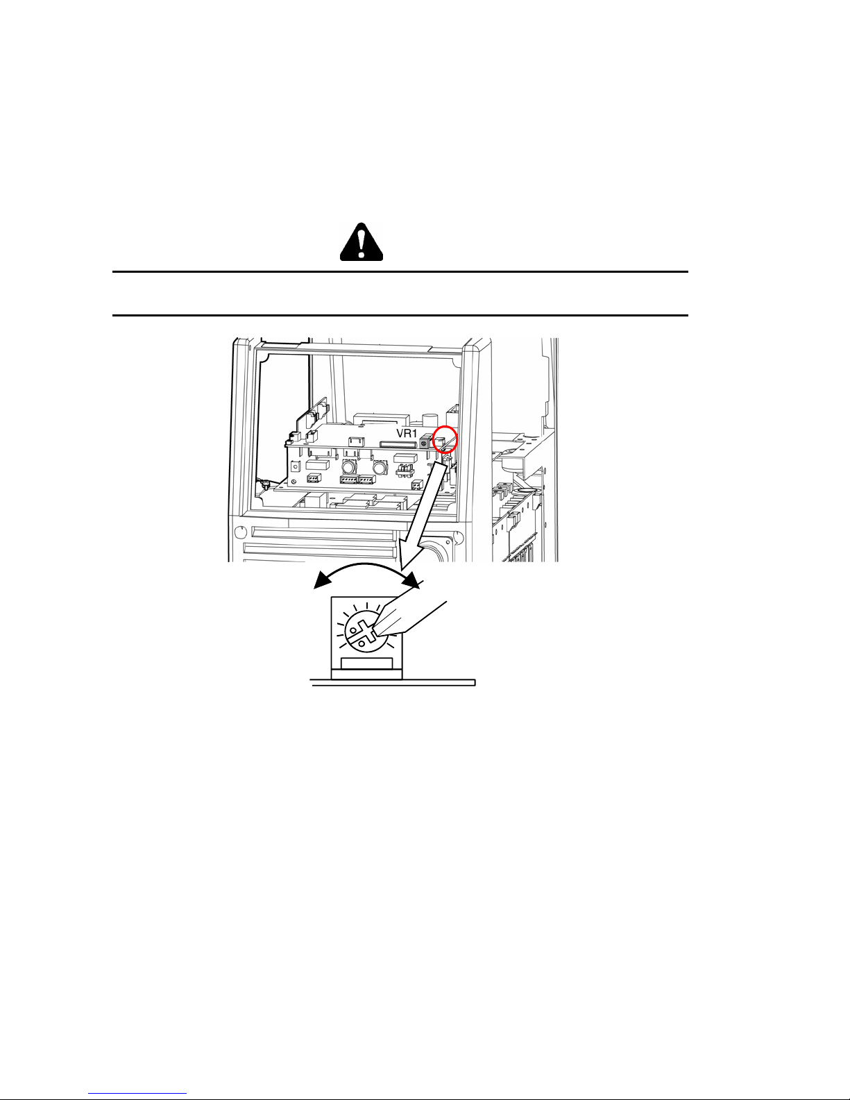
d) Turning the VRD ON/OFF (see Figure 13).
• To turn VRD ON: rotate the trim potentiometer (VR1) on the display PCB fully
clockwise. When VRD is turned ON check that it operates as per VRD Specifications
on page 49.
• To turn VRD OFF: rotate the trim potentiometer (VR1) on the display PCB fully
counter-clockwise.
WARNING 6
The VRD ON/OFF trim potentiometer MUST ONLY be positioned fully clockwise OR fully
counter clockwise as the VRD function will be unknown for every other position.
Figure 13.
VRD ON/OFF Step D
51
Page 58

SECTION 12: POWER SOURCE ERROR CODES
Description Possible Cause Remedy Remarks
1 E01 error code displayed
Temperature sensor TH1
(protects IGBTs) is greater
than 80ºC for about 1
second.
2 E02 error code displayed
Temperature sensor TH2
(protects secondary
diodes) is greater than
80ºC for about 1 second.
3 E03 error code displayed
Primary (input) current
too high.
4 E04 error code displayed
Output voltage exceeds
the secondary voltage
specification.
5 E11 error code displayed
Over Primary supply
(input) voltage at primary
capacitors is exceeded for
one second.
The Welding Power
A
Source’s duty cycle
has been exceeded.
Fan ceases to
B
operate.
C
Air flow is restricted
by vents being
blocked.
The Welding Power
A
Source’s duty cycle
has been exceeded.
Fan ceases to
B
operate.
C
Air flow is restricted
by vents being
blocked.
Primary current is
A
too high because
welding arc is too
long.
B
Mains supply
voltage is
more than 10%
below
nominal voltage.
TIG torch cable
and/or work lead are
too long or leads are
coiled.
Primary supply
voltage is greater
than the nominal
voltage plus 10%.
Let Power Source
A
cool down then keep
within its duty cycle.
Have an accredited
B
Thermal Arc Service
Agent investigate.
C
Unblock vents then
let Power Source
cool down.
Let Power Source
A
cool down then keep
within its duty cycle.
Have an accredited
B
Thermal Arc Service
Agent investigate.
Unblock vents then
C
let Power Source
cool down.
Reduce length of
A
welding arc.
Have an accredited
B
Thermal Arc Service
Agent or a qualified
electrician check for
low
Mains voltage.
Reduce the length of
the TIG torch cable
and/or work lead or
un-coiled leads.
Have an accredited
Thermal Arc Service
Agent or a qualified
electrician check the
Primary voltage.
Weld current ceases.
Buzzer sounds
constantly.
Fan operates at max
speed.
E01 resets when TH1
decreases
to 70ºC for about 30
seconds.
Weld current ceases.
Buzzer sounds
constantly.
Fan operates at max
speed.
E02 resets when TH1
decreases to 70ºC for
about 30 seconds.
Weld current ceases.
Buzzer sounds
constantly.
Switch machine OFF
then ON to reset E03
error.
Weld current ceases.
Buzzer sounds
constantly.
Switch machine off
then on to reset E04
error.
Weld current ceases.
Buzzer sounds
constantly.
Error code E11
automatically will reset
when the voltage
reduces.
52
Page 59

Description Possible Cause Remedy Remarks
6 E12 error code displayed
Under mains supply
(input) voltage primary
capacitors is reduced for
one second.
7 E14 error code displayed
Under mains supply
(input) voltage warning
primary capacitors is
reduced for one second.
8 E81 error code displayed
Wrong Primary supply
(input)
voltage connected.
9 E82 error code displayed
Link switch plug not
connected.
10 E83 error code displayed
CPU checks mains supply
(input) voltage when the
ON/OFF switch on rear
panel of machine is turned
ON.
Mains supply
voltage is down to a
dangerously low
level.
Mains supply
voltage is less than
the nominal
operating voltage
less 10%.
When 3 phase
machine is first
turned ON with the
wrong Primary
supply (input)
voltage connected.
Link switch plug not
connected.
The Primary supply
(input) voltage
fluctuates and
is not stable.
Have an accredited
Thermal Arc Service
Agent or a qualified
electrician check the
Mains voltage.
Have an accredited
Thermal Arc Service
Agent or a qualified
electrician check the
Mains voltage.
Have an accredited
Thermal Arc Service
Agent or a qualified
electrician check
the Mains voltage.
Have an accredited
Thermal Arc Service
Agent check
connector plug on
input PCB.
Have an accredited
Thermal Arc Service
Agent check
connector plug on
input PCB and the
Mains voltage.
Weld current ceases.
Buzzer sounds
constantly.
Error code E12
automatically will reset
when the voltage
increases.
Weld current available.
Buzzer sounds
intermittently. Error
code E14 automatically
will reset when the
voltage increases.
No weld current is
available. Buzzer
sounds constantly.
Switch machine OFF.
No weld current is
available. Buzzer
sounds constantly.
Switch machine OFF.
No weld current is
available.
Buzzer sounds
constantly.
Switch machine OFF
then ON to reset E83
error.
11 E85 error code
displayed
Pre-charge abnormality.
Due to malfunction
inside the Welding
Power Source,
primary capacitors
are not charging
correctly.
12 E93 error code displayed
Memory chip (EEPROM)
on control PCB can not
read/write weld
parameters.
Memory chip
(EEPROM) error.
Have an Accredited
Thermal Arc
Service Agent
service the
machine.
Have an accredited
Thermal Arc Service
Agent check the
control PCB.
53
No weld current is
available. Buzzer
sounds constantly.
Switch machine OFF
then ON to reset E85
error.
Weld current ceases.
Buzzer sounds
constantly.
Switch machine OFF.
Page 60

Description Possible Cause Remedy Remarks
13 E94 error code displayed
Temperature sensor TH1
for IGBTs or sensor TH2
for secondary diodes are
open circuit.
14 E99 error code displayed
Mains supply (input)
voltage has been turned
OFF but control circuit has
power from the primary
capacitors.
The Welding Power
Source’s
temperature sensors
have malfunctioned.
A
Main ON/OFF switch
on machine has
B
been turned OFF.
Mains supply (input)
voltage has been
turned OFF.
Have an accredited
Thermal Arc Service
Agent check or
replace the
temperature
sensors.
A
Turn ON/OFF Switch
ON.
B
Have an accredited
Thermal Arc Service
Agent or a qualified
electrician check the
Mains voltage and
fuses.
Weld current ceases.
Buzzer sounds
constantly.
Switch machine OFF.
Weld current ceases.
Buzzer sounds
constantly.
Must switch machine
OFF then ON to reset
E99 error.
54
Page 61

Page 62
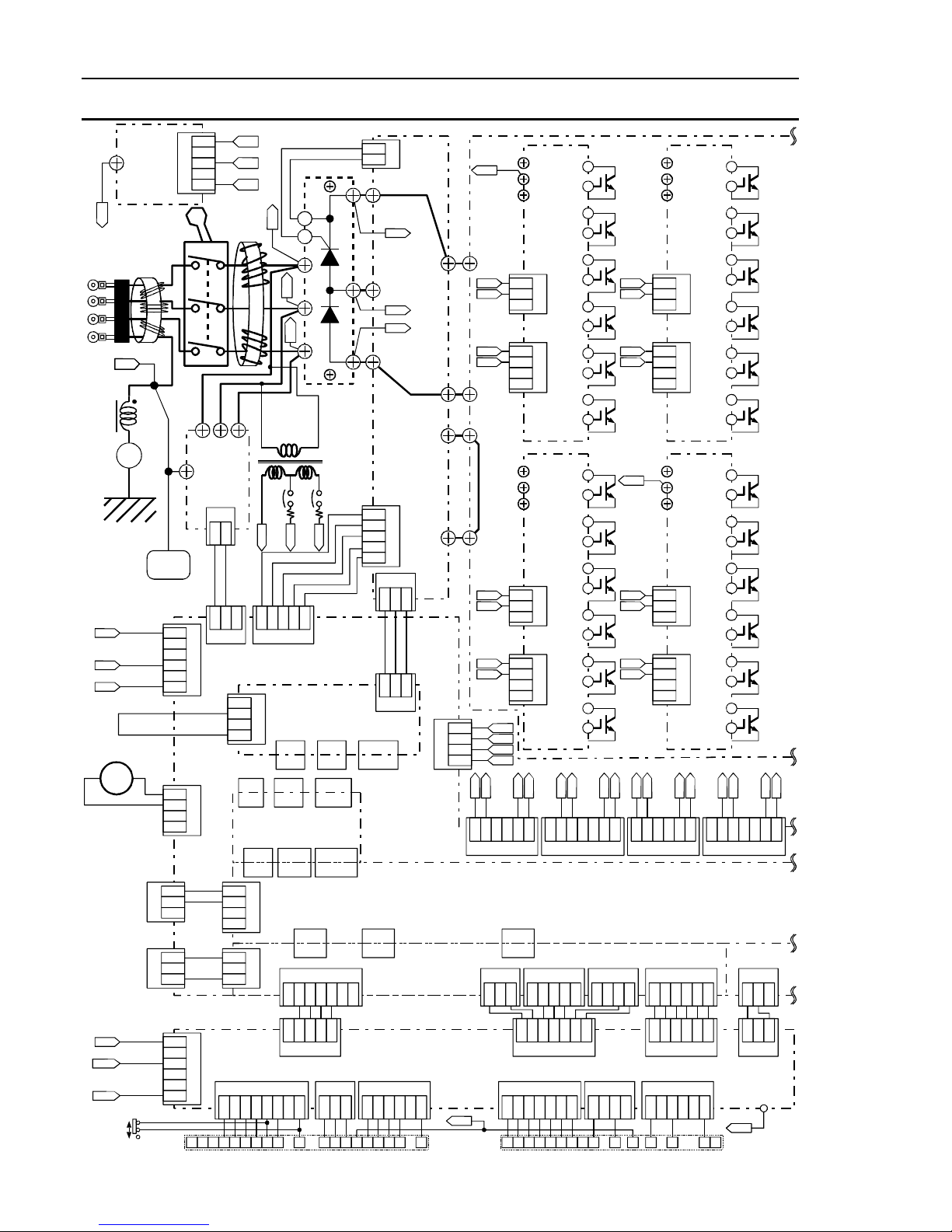
APPENDIX A - INTERCONNECT DIAGRAM
PCB22
CE
TB1
Filter
Circuit
Bord
[WK-5022]
GND
L101
GND
L103
Ground
+
SIDE CHASSIS 1
PANEL
N
P
R2
FAN1
+-
REAR
1
2
CN33
3
1
2
CN18
3
1
2
3
CN1
4
5
S1
PCB21
E
Filter
Circuit Bord
[WK-4917]
1
2
3
4
CN1
5
6
1
2
3
CN11
4
R
S
T
R
L102
0V
0V
CN1
1
2
0V
1 2 3
1 2 3 4 5
CN2
CN3
1
2
3
CN4
4
CN32
CN31 CN30
CN32
Conect Circuit Bord
[WK-5696]
CN131 CN130
1
2
3
CN20
4
1
2
CN20
3
1
2
D1
+
(1)
K(7)
G(6)
R(3)
(0)
S
S(4)
T
T(5)
-
(2)
400V
T1
24V
115V
MCB1
MCB2
24V
115V
PCB4
Detect
Circuit Bord
[WK-4819]
CN5 CN6 CN4
CN30CN31
PCB5
CN3
P
P
TB1
R2
R2
N
N
TB4
PCB2
Link
Circuit Bord
[WK-5597]
1
2
3
CN2
4
5
CN1
1
2 3
1
2 3
CN7
CN1CN6CN5
PCB3
Control Souce
Circuit Bord
TB2
TB3
CN7
1
2
3
4
[WK-5548]
CN130CN131
CN132
CN132
CN27
CN27
CN1
1
2 3 4 5 6 7 1 2 3
CN18
CN18
PCB7
Filter Circuit Bord
[WK-5689]
TB13
UB3
TB14
TB15
PCB1
Main
Circuit
Bord
[WK-5493]
TB1
G1
E1
G2
E2
TB4
TB2
TB18
TB19
TB20
TB3
G3
E3
G4
E4
CT1
CT2
CT3
CT4
E1
G1
2 3 4 5 6
1
CN20
CN3
CN3
CN13
C
CE
E
PCB8
IGBT
Gate
Circuit
Bord
[WK-5479]
1
2
CN1
3
1
2
3
CN2
4
C
CE
E
PCB9
IGBT
Gate
Circuit
Bord
[WK-5479]
1
2
CN1
3
1
2
3
CN2
4
E5
G5
1
CN15
1 2 3 4 5
Q1
C
G
E
Q2
C
G
E
Q3
C
G
E
Q4
C
G
E
Q5
C
G
E
Q6
C
G
E
C
Q7
G
E
C
Q8
G
E
C
Q9
G
E
C
Q10
G
E
C
Q11
G
E
C
Q12
G
E
E2
G2
2 3 4 5 6 7
CN21
CN16
1
2 3 4
TB10
TB11
TB12
G4
E4
G3
E3
TB5
UB1
TB6
TB7
G7
E7
G8
E8
E6
E7
G6
2 3 4 5 6
1
PCB6
Control
Circuit Bord
[WK-5688]
C
CE
E
[WK-5479]
1
2
3
1
2
3
4
C
CE
E
[WK-5479]
1
2
3
1
2
3
4
G7
CN22
CN2
1
2 3 4 5 6
PCB10
IGBT
Gate
Circuit
Bord
CN1
CN2
PCB11
IGBT
Gate
Circuit
Bord
CN1
CN2
E3
G3
C
Q13
G
E
C
Q14
G
E
C
Q15
G
E
C
Q16
G
E
C
Q17
G
E
C
Q18
G
E
C
Q19
G
E
C
Q20
G
E
C
Q21
G
E
C
Q22
G
E
C
Q23
G
E
C
Q24
G
E
E8
G8
2 3 4 5 6 7
1
CN23
1
CN19
2 3
E4
G4
0V
24V
115V
1
2
3
4
CN1
5
6
19P
S3
14P
CON2 CON1
1
2 3 4 5 6 7
C
U J H N KVAB MLRF D PG ETS
1 2 3 4 5 1 2 3 6 74 5
CN3
CN7
Socket Receptacle Circuit Bord
PCB17
[WK-5699]
1
CN6
2 38
CN5
1
2 3 4 5 6
55
EC
CN4 CN2
CN10
1
2 3 4 5 6 7
D E H F N JCKGBILANM
1
CN9
2 3 4
1 2 3 4 5 6
CN8
1
2 3 4 5 6
1 2 3
CN15
TB1
EC
Page 63
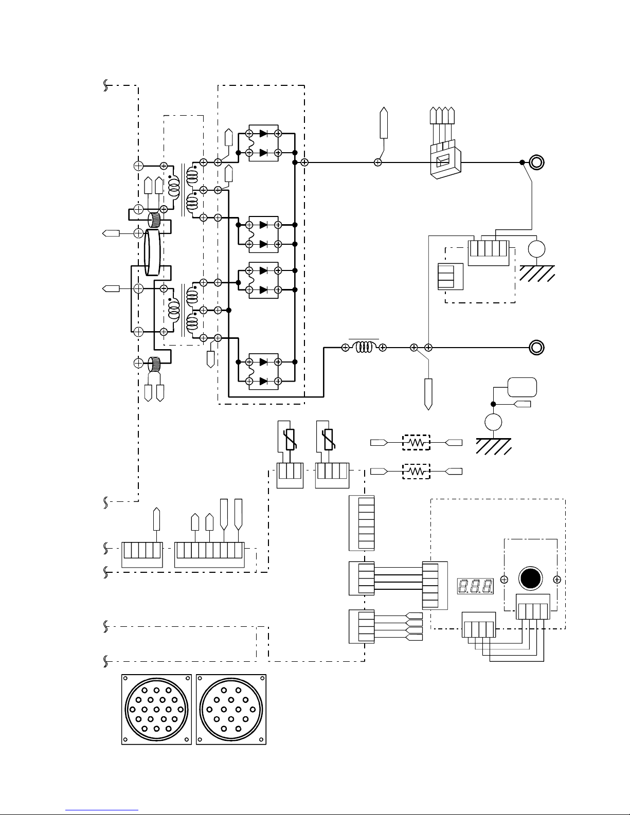
UB2
UB4
TB7
TB21
TB8
TB16
TRANS
[WK-5594]
CT2
CT1
CT2
L1
PCB14
Bord
TB35
TB33
TB34
TB30
TB32
PCB15
DIODE Snubber
Circuit Bord
[WK-5606]
AC2 AC1
D7
D2
D5
IS
-15
+15
GND
SH.DET+
4
3
2
1
TO1
+Output
Terminal
HCT1
1
2
3
2 3 4 5
1
CN1
PCB18
Filter Circuit
CN3
Bord
[WK-5499]
Ground
+
SIDE CHASSIS 3
TB17
1
TB22
CT3
2 3 4 5
CN8
TB31
D4
AC4
FCH1
TO2
-Output
Terminal
FRONT
+
PCB12
Panel
PANEL
EB
Ground
PCB13
Encorder
Board
[WK-5528]
CN1
1 2 3 4
CT4
CT3
SH.DET-
R2
EB
AC4
AC2
2 3 4 5 6 789
1
CN9
TH2 TH1
R3
1
2 3
CN9
SH.DET-
SH.DET+
1
2 3 4
CN8
CN17
CN21
CN1
1
2
3
4
5
6
7
1
2
3
4
1
2
3
4
+15
-15
IS
GND
UB2UB1
SIDE CHASSIS 2
UB4UB3
Circuit Board
[WK-5527]
1
2
3
4
CN2
5
6
CN1
1 2 3 4
A
L
M
B
NU
CV
RSHD
GFE
JKTP
CLNH
CON2 CON1
AJ
BK I
DMG
FE
56
Page 64

APPENDIX B - ARCMASTER 400 MST ACCESSORIES
PART NO. DESCRIPTION
10-2007 Remote Foot control 7.6m lead and plug
10-2005 Remote Hand Pendant 7.6m lead and plug
10-2096 14 Pin Plug for Remote or TIG Torch Button
10-2097 Cable Clamp for 14 Pin Plug
10-4035 Thermal Arc Inverter cart
57
Page 65

Page 66

LIMITED WARRANTY AND SCHEDULE
This information applies to Thermadyne products that were purchased in the United Kingdom
April 2006
Thermadyne guarantees the proposed product to be free from defects in material or workmanship when operated in
accordance with the written instructions as defined in the owner’s manual supplied with the machine. Thermadyne
welding products are manufactured for use by commercial and industrial users and trained personnel with experience
in the use and maintenance of electrical welding and cutting equipment.
Thermadyne warranty will not apply to:
1. Equipment that has been modified by any other party other than Thermadyne’s own service personnel or
with prior written consent obtained from Thermadyne service department (UK).
2. Equipment that has been used beyond the specifications established in the owners manual.
3. Installation not in accordance with the installation/service manual.
4. Failure to clean and maintain the machine as set forth in the owner, installation or service manual.
If warranty is being sought, please contact Thermadyne's UK warranty department for a warranty authorization returns
form.
Welding Equipment - Limited Warranty Period
Product Period
200S, 300S, 400S, 200TS, 300TS, 400TS, 400 MST, 200AC/DC, 300AC/DC,
PowerMaster 320SP, 400SP, 500SP,
Fabricator 200, Ultrafeed VA4000, Portafeed VS212 3 Years
150SE, 155SE, 250SE, 400SE, 250TE, 400TE, 180AC/DC, 250AC/DC, 400AC/DC
Fabricator 250, Fabricator 330, Fabricator 400, Fabricator 450, 220GMS 2 Years
Options and Accessories 6 Months
Repair and Replacement Parts 3 Months
Torch Consumables None
Cutting Equipment -Limited Warranty Period
Product Period
CutMaster 38, 51, 81,101, 151 3 Years
PakMaster 150XL, Drag-Gun Plus 2 Years
CutSkill C-35A, C-70A, C-100A, Drag-Gun 1 Year
1TorchTM, SureLokTM Torches and PCH 120 1 Year
Other Torches 6 Months
Repair Parts 3 Months
Arc Accessories - Limited Warranty Period
Product Period
All Products 1 Month
Consumables None
Torch Consumables None
Page 67

GLOBAL CUSTOMER SERVICE CONTACT INFORMATION
Thermadyne USA
2800 Airport Road
Denton, Tx 76207 USA
Telephone: (940) 566-2000
800-426-1888
Fax: 800-535-0557
Email: [email protected]
Thermadyne Canada
2070 Wyecroft Road
Oakville, Ontario
Canada, L6L5V6
Telephone: (905)-827-1111
Fax: 905-827-3648
Thermadyne Europe
Europe Building
Chorley North Industrial Park
Chorley, Lancashire
England, PR6 7Bx
Telephone: 44-1257-261755
Fax: 44-1257-224800
Thermadyne Asia Sdn Bhd
Lot 151, Jalan Industri 3/5A
Rawang Integrated Industrial Park - Jln Batu Arang
48000 Rawang Selangor Darul Ehsan
West Malaysia
Telephone: 603+ 6092 2988
Fax : 603+ 6092 1085
Cigweld, Australia
71 Gower Street
Preston, Victoria
Australia, 3072
Telephone: 61-3-9474-7400
Fax: 61-3-9474-7510
Thermadyne Italy
OCIM, S.r.L.
Via Benaco, 3
20098 S. Giuliano
Milan, Italy
Tel: (39) 02-98 80320
Fax: (39) 02-98 281773
Thermadyne, China
RM 102A
685 Ding Xi Rd
Chang Ning District
Shanghai, PR, 200052
Telephone: 86-21-69171135
Fax: 86-21-69171139
Thermadyne International
2070 Wyecroft Road
Oakville, Ontario
Canada, L6L5V6
Telephone: (905)-827-9777
Fax: 905-827-9797
Page 68

World Headquarters
Thermadyne Holdings Corporation
Suite 300, 16052 Swingley Ridge Road
St. Louis, MO 63017
Telephone: (636) 728-3000
Fascimile:
(636) 728-3010
Email: sales@thermalarc.com
www.thermalarc.com
 Loading...