

Page 1
INVERTER
ARC
WELDER
MODEL 250S DC CC
STICK
TIG - Lift Start
November 11, 2003 Manual No. 430429-506
OPERATING MANUAL
Page 2

Page 3

CONTENTS
SYMBOL LEGEND ............................................................................................................................................................5
STATEMENT OF WARRANTY........................................................................................................................................6
1.0 GENERAL INFORMATION.........................................................................................................................................7
1.01 Notes, Cautions and Warnings................................................................................................................................7
1.02 Important Safety Precautions....................................................................................................................................7
1.03 Publications.............................................................................................................................................................8
1.04 Note, Attention et Avertissement.............................................................................................................................9
1.05 Precautions De Securite Importantes.......................................................................................................................9
1.06 Documents De Reference......................................................................................................................................11
2.0 INTRODUCTION AND DESCRIPTION ...................................................................................................................13
2.01 Description .............................................................................................................................................................13
2.02 Functional Block Diagrams....................................................................................................................................14
2.03 Transporting Methods.............................................................................................................................................14
3.0 INSTALLATION RECOMMENDATIONS................................................................................................................15
3.01 Environment...........................................................................................................................................................15
3.02 Location..................................................................................................................................................................15
3.03 Electrical Input Connections...................................................................................................................................16
3.03.01 Electrical Input Requirements.......................................................................................................................16
3.03.02 Input Power ...................................................................................................................................................18
3.03.03 High Frequency Introduction.........................................................................................................................19
3.03.04 High Frequency Interference......................................................................................................................... 19
3.04 Specifications .........................................................................................................................................................20
3.05 Duty Cycle..............................................................................................................................................................21
4.0 OPERATOR CONTROLS...........................................................................................................................................23
4.01 Pro-Lite 250S Controls...........................................................................................................................................23
4.02 Weld Parameter Description...................................................................................................................................25
4.03 Weld Parameters for Pro-Lite 250S........................................................................................................................26
4.04 Power Source Features...........................................................................................................................................26
5.0 SET-UP FOR SMAW (STICK) AND GTAW (TIG) ..................................................................................................28
6.0 SEQUENCE OF OPERATION....................................................................................................................................29
6.01 Stick Welding.........................................................................................................................................................30
6.02 DC LIFT TIG Welding...........................................................................................................................................30
7.0 BASIC TIG WELDING GUIDE..................................................................................................................................31
7.01Electrode Polarity....................................................................................................................................................31
7.02 Tungsten Electrode Current Ranges .......................................................................................................................31
7.03 Tungsten Electrode Types ......................................................................................................................................31
7.04 Guide for Selecting Filler Wire Diameter...............................................................................................................32
7.05 Shielding Gas Selection..........................................................................................................................................32
7.06 TIG Welding Parameters for Low Carbon & Low Alloy Steel Pipe......................................................................32
7.07 Welding Parameters for Steel.................................................................................................................................33
8.0 BASIC ARC WELDING GUIDE................................................................................................................................34
8.01Electrode Polarity....................................................................................................................................................34
8.02 Effects of Stick Welding Various Materials...........................................................................................................34
9.0 BASIC TROUBLESHOOTING...................................................................................................................................37
9.01 TIG Welding Problems...........................................................................................................................................37
9.02 Stick Welding Problems.........................................................................................................................................39
9.03 Power Source Problems..........................................................................................................................................41
10.0 VOLTAGE REDUCTION DEVICE (VRD)..............................................................................................................42
10.01 VRD Specification................................................................................................................................................42
10.02 VRD Maintenance................................................................................................................................................42
11.0 POWER SOURCE ERROR CODES.........................................................................................................................43
12.0 PARTS LIST..............................................................................................................................................................46
APPENDIX A - INTERCONNECT DIAGRAM...............................................................................................................50
APPENDIX B - AUTOMATION ......................................................................................................................................52
3
Page 4

PAGE LEFT INTENTIONALLY BLANK
4
Page 5
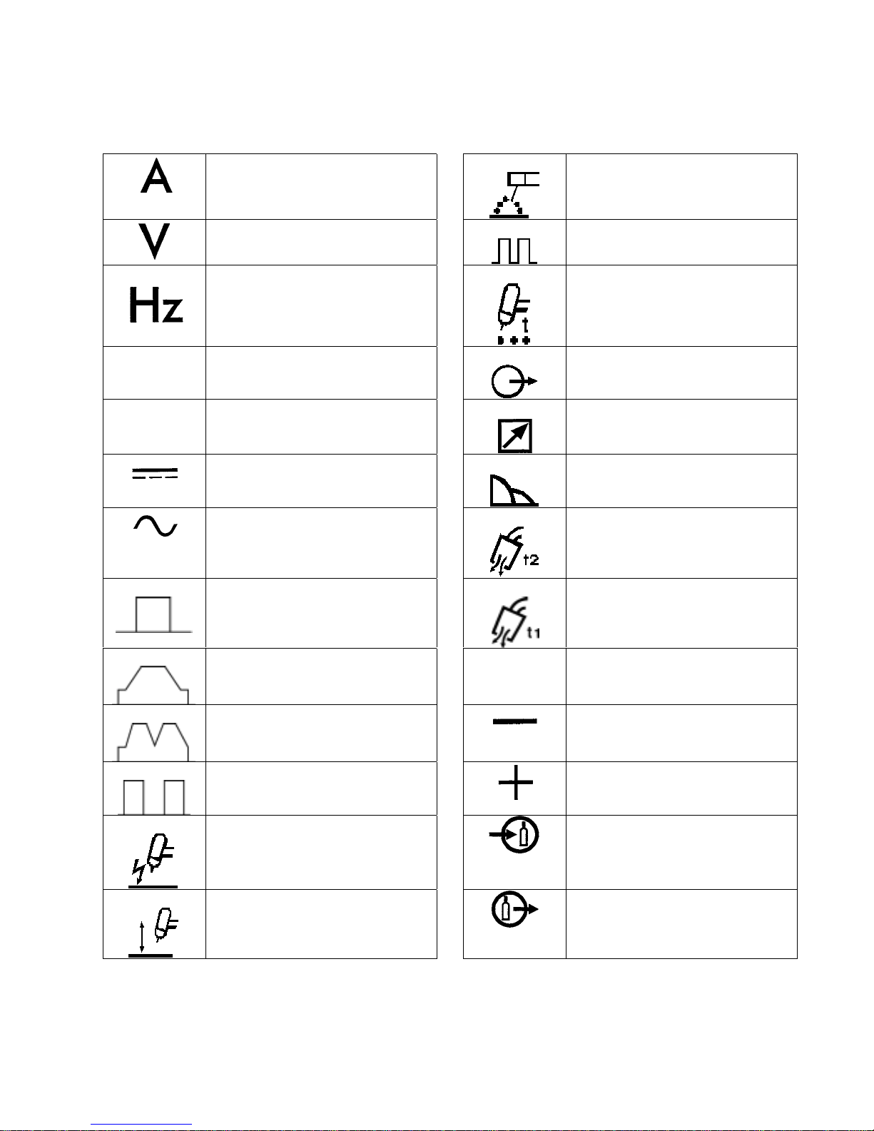
SYMBOL LEGEND
Amperage STICK (Shielded Metal Arc
Voltage Pulse Current Function
Hertz (frequency) Spot Time (GTAW)
SMAW)
SEC
%
Seconds Remote Control (Panel/Remote)
Percent Remote Function
DC (Direct Current) Arc Control (SMAW)
AC (Alternating Current Gas Post-Flow
Standard Function Gas Pre-Flow
Slope Function
VRD
Slope W/Repeat Function Negative
Voltage Reduction Device
Circuit
Spot Function Positive
Impulse Starting (High
Frequency GTAW)
Touch Start (Lift Start TIG
circuit GTAW)
Gas Input
Gas Output
5
Page 6

STATEMENT OF WARRANTY
LIMITED WARRANTY: Thermal Arc
authorized distributors hereafter “Thermal; Arc” that its products will be free of defects in workmans hip or material. Should any
failure to con form to thi s wa rr anty a ppear with i n th e time p er iod a ppl ica bl e to th e Th er mal Ar c pr od ucts as s tate d bel ow, Th ermal Arc
shall, upon notificati on the reof and s ubstan tiation that the pr oduct ha s been stored , ins talle d, opera ted, a nd ma intaine d in accordance
with Thermal Arc’s specifications, instructions, recommendations and recognized standard industry practice, and not subject to
misuse, repair, neglect, alteration, or accident, correct such defects by s uitable repair or replacement, at Thermal Ar c’s sole option, of
any components o r parts of the product determined by Thermal Arc to be defective.
THERMAL ARC MAKES NO OTHER WARRANTY, EXPRESS OR IMPLIED. THIS WARRANTY IS EXCLUSIVE AND IN LIEU
OF ALL OTHERS, INCLUDING, BUT NOT LIMITED TO ANY WARRANTY OF MERCHANTABILITY OR FITNESS FOR ANY
PARTICULAR PURPOSE.
LIMITATION OF LIABILITY: Thermal Arc shall not under any cir cumstan ces be liable for s pecial, ind ire ct or con sequentia l d amages,
such as, but not l imited to, lost profi ts and busi ness in terruption . The re medies of the Pur chaser set forth h erein ar e exclus ive and the
liability of Thermal Arc with respect to any contract, or anything done in connection therewith such as the performance or breach
thereof, or from the ma nufacture, sale, delivery, resale, or use of any goods covered by or furnished by Thermal Arc whether arising
out of contract, negligence, strict tort, or under any warranty, or otherwise, shall not, except as expressly provided herein, exceed the
price of the goods upon which such liability is based. No employee, agent, or representative of Thermal Arc is authorized to change
this warranty in any way or grant an y other warranty.
PURCHASER'S RIGHTS UNDER THIS WARRANTY ARE VOID IF REPLACEMENT PARTS OR ACCESSORIES ARE USED
WHICH IN THERMAL ARC’S SOLE JUDGEMENT MAY IMPAIR THE SAFETY OR PERFORMANCE OF ANY THERMAL ARC
PRODUCT.
PURCHASER'S RIGHTS UNDER THIS WARRANTY ARE VOID IF THE PRODUCT IS SOLD TO PURCHASER BY NONAUTHORIZED PERSONS.
®
, Inc., A Thermadyne Company, hereafter, “Thermal Arc” warrants to customers of its
The warran ty is effective fo r the time stated below beginnin g on the date that th e authoriz ed distributor delivers the products to the
Purchaser. Notw iths tan ding the for egoin g, in no even t shal l the wa rra nty per iod ex tend more tha n the time sta ted plus one year from
the date Thermal Arc delivered the prod uct to the authorized distr ibutor.
POWER SUPPLIES POWER SUPPLIES & WIRE FEEDERS LABOR
MAIN POWER MAGNETICS (STATIC & ROTATING) 3 YEAR 3 YEAR
ORIGINAL MAIN POWER RECTIFIER 3 YEAR 3 YEAR
POWER SWITCHING SEMI-CONDUCTORS & CONTROL PC BOARD 3 YEAR 3 YEAR
ALL OTHER CIRCUITS AND COMPONENTS INCLUDING 1 YEAR 1 YEAR
BUT NOT LIMITED TO, CONTACTORS, RELAYS,
SOLENOIDS, PUMPS, SWITCHES, MOTORS
ENGINES: ENIGINES ARE NOT WARRANTED BY THERMAL ARC, ALTHOUGH MOST ARE WARRANTED BY THE ENGINE
MANUFACTURER, SEE THE ENGINE MANUFACTUR ES WARRA NT Y FOR DE TAILS .
CONSOLES, CONTROL EQUIPMENT, HEAT 1 YEAR 1 YEAR
EXCHANGES, AND ACCESSORY EQUIPMENT
PLASMA TORCH AND LEADS, AND REMOTE CONTRO LS
180 DAYS 180 DAYS
REPAIR/REPLACEMENT PARTS 90 DAYS 90 DAYS
Warranty repair s or replace ment cla ims under this limi ted warr anty must be s ubmitted to Th ermal Arc by an a uthoriz ed Thermal Arc
repair facility within thirty (30) days of purchaser’s notice of any Warranty Claim. No transportation costs of any kind will be paid
under this warranty. Transportation charges to send products to an authorized warranty repair facility shall be the responsibility of the
Purchaser. All returned goods shall be at the Purchaser’s risk and expense. This warranty supersedes all previous Thermal Arc
warranties.
Thermal Arc® is a Registered Trademark of Thermadyne Industries Inc.
Effective April 1, 2002
6
Page 7
1.0 GENERAL INFORMATION
1.01 Notes, Cautions and Warnings
Throughout this manual, notes, cautions, and
warnings are used to highlight important
information. These highlights are categorized as
follows:
NOTE
An operation, procedure, or
background information which
requires additional emphasis or is
helpful in efficient operation of the
system.
CAUTION
A procedure which, if not properly
followed, may cause damage to the
equipment.
WARNING
A procedure which, if not properly
followed, may cause injury to the
operator or others in the operating
area.
1.02 Important Safety Prec autions
WARNING
OPERATION AND
MAINTENANCE OF ARC
WELDING EQUIPMENT CAN BE
DANGEROUS AND HAZARDOUS
TO YOUR HEALTH.
To prevent possible injury, read,
understand and follow all warnings,
safety precautions and instructions
before using the equipment. Call 1800-462-2782 or your local distributor
if you have any questions.
GASES AND FUMES
Gases and fumes produced during the Arc
welding/cutting process can be dangerous and
hazardous to your health.
• Keep all fumes and gases from the breathing
area. Keep your head out of the welding
fume plume.
• Use an air-supplied respirator if ventilation is
not adequate to remove all fumes and gases.
• The kinds of fumes and gases from the arc
welding/cutting depend on the kind of
metal being used, coatings on the metal, and
the different processes. You must be very
careful when cutting or welding any metals
which may contain one or more of the
following:
Antimony Chromium Mercury
Arsenic Cobalt Nickel
Barium Copper Selenium
Beryllium Lead Silver
Cadmium Manganese
Vanadium
• Always read the Material Safety Data Sheets
(MSDS) that should be supplied with the
material you are using. These MSDSs will
give you the information regarding the kind
and amount of fumes and gases that may be
dangerous to your health.
• For information on how to test for fume s and
gases in your workplace, refer to item 1 in
Subsection 1.03, Publications in this manual.
• Use special equipment, such as water or
down draft welding/cutting tables, to
capture fumes and gases.
• Do not use the welding torch in an area
where combustible or explosive gases or
materials are located.
• Phosgene, a toxic gas, is generated from the
vapors of chlorinated solven ts and cleanser s.
Remove all sources of these vapors.
ELECTRIC SHOCK
Electric Shock can injure or kill. The arc welding
process uses and produces high voltage electrical
energy. This electric energy can cause severe or
fatal shock to the operator or others in the
workplace.
• Never touch any parts that are electrically
“live” or “hot.”
• Wear dry gloves and clothing. Insulate
yourself from the work piece or other parts
of the welding circuit.
• Repair or replace all worn or damaged parts.
• Extra care must be taken when the workpla ce
is moist or damp.
7
Page 8
• Install and maintain eq uipment according to
NEC code, refer to item 4 in Subsection 1.03,
Publications.
• Disconnect power source before performing
any service or repairs.
• Read and follow all the instructions in the
Operating Manual.
FIRE AND EXPLOSION
Fire and explosion can be caused by hot slag,
sparks, or the arc weld.
• Be sure there is no combustible or flammable
material in the workplace. Any material that
cannot be removed must be protec te d.
• Ventilate all flammable or explosive vapors
from the workplace.
• Do not cut or weld on containers that may
have held combustibles.
• Provide a fire watch when working in an
area where fire hazards may exist.
• Hydrogen gas may be formed and trapped
under aluminum workpieces when they are
cut underwater or while using a water table.
DO NOT cut aluminum alloys underwater
or on a water table unle ss the hydrogen ga s
can be eliminated or dissipated. Trapped
hydrogen gas that is ignited will cause an
explosion.
NOISE
Noise can cause permanent hearing loss. Arc
welding/cutting processes can cause noise levels
to exceed safe limits. You must protect your ears
from loud noise to prevent permanent loss of
hearing.
• To protect your hearing from loud noise,
wear protective ear plugs and/or ear muffs.
Protect others in the workplace.
• Noise levels should be measured to be sure
the decibels (sound) do not exceed safe
levels.
• For information on how to test for noise, see
item 1 in Subsection 1.03, Publications, in
this manual.
ARC WELDING RAYS
Arc Welding/Cutting Rays can injure your eyes
and burn your skin. The arc welding/cutting
process produces very bright ultra violet and infra
red light. These arc rays will damage your eyes
and burn your skin if you are not properly
protected.
• To protect your eyes, always wear a welding
helmet or shield. Also always wear safety
glasses with side shields, goggles or other
protective eye wear.
• Wear welding gloves and suita ble clothing to
protect your skin from the arc rays and
sparks.
• Keep helmet and safety glasses in good
condition. Replace lenses when cracked,
chipped or dirty.
• Protect others in the wor k area from the arc
rays. Use protective booths, screens or
shields.
• Use the shade of lens as recommended in
Subsection 1.03, item 4.
1.03 Publications
Refer to the following standards or their latest
revisions for more information:
1. OSHA, SAFETY AN D HEA L TH ST AN D ARDS,
29CFR 1910, obtainable from the
Superintendent of Documents, U.S.
Government Printing Office, Washington, D.C.
20402
2. ANSI Standard Z49.1, SAFETY IN WELDING
AND CUTTING, obtainable from the American
Welding Society, 550 N.W. LeJeune Rd, Miami,
FL 33126
3. NIOSH, SAFETY AND HEALTH IN ARC
WELDING AND GAS WELDING AND
CUTTING, obtainable from the Superintendent
of Documents, U.S. Government Printing
Office, Washington, D.C. 20402
4. ANSI Standard Z87.1, SAFE PRACTICES FOR
OCCUPATION AND EDUCATIONAL EYE
AND FACE PROTECTION, obtainable from
American National Standards Institute, 1430
Broadway, New York, NY 10018
5. ANSI Standard Z41.1, STANDARD FOR MEN’S
SAFETY-TOE FOOTWEAR, obtainable from
the American National Standards Institute,
1430 Broadway, New York, NY 10018
8
Page 9
6. ANSI Standard Z49.2, FIRE PREVENTION IN
THE USE OF CUTTING AND WELDING
PROCESSES, obtainable from American
National Standards Institute, 1430 Broadway,
New York, NY 10018
7. AWS Standard A6.0, WELDING AND
CUTTING CONTAINERS WHICH HAVE
HELD COMBUSTIBLES, obtainable from
American Welding Society, 550 N.W. LeJeune
Rd, Miami, FL 33126
8. NFPA Standard 51, OXYGEN-FUEL GAS
SYSTEMS FOR WELDING, CUTTING AND
ALLIED PROCESSES, obtainable from the
National Fire Protection Association,
Batterymarch Park, Quincy, MA 02269
9. NFPA Standard 70, NATIONAL ELECTRICAL
CODE, obtainable from the National Fire
Protection Association, Batterymarch Park,
Quincy, MA 02269
10. NFPA Standard 51B, CUTTING AND
WELDING PROCESSES, obtainable from the
National Fire Protection Association,
Batterymarch Park, Quincy, MA 02269
11.CGA Pamphlet P-1, SAFE HANDLING OF
COMPRESSED GASES IN CYLINDERS,
obtainable from the Compressed Gas
Association, 1235 Jefferson Davis Highway,
Suite 501, Arlington, VA 22202
12. CSA Standard W117.2, CODE FOR SAFETY IN
WELDING AND CUTTING, obtainable from
the Canadian Standards Association, Standards
Sales, 178 Rexdale Boulevard, Rexdale, Ontario,
Canada M9W 1R3
13. NWSA booklet, WELDING SAFETY
BIBLIOGRAPHY obtainable from the National
Welding Supply Association, 1900 Arch Street,
Philadelphia, PA 19103
14. American Welding Society Standard AWSF4.1,
RECOMMENDED SAFE PRACTICES FOR
THE PREPARATION FOR WELDING AND
CUTTING OF CONTAINERS AND PIPING
THAT HAVE HELD HAZARDOUS
SUBSTANCES, obtainable from the American
Welding Society, 550 N.W. LeJeune Rd, Miami,
FL 33126
15. ANSI Standard Z88.2, PRACTICE FOR
RESPIRATORY PROTECTION, obtainable
from American National Standards Institute,
1430 Broadway, New York, NY 10018
des informations à caractère important. Ces mises
en relief sont classifiées comme suit :
NOTE
Toute opération, procédure ou
renseignement général sur lequel il
importe d’insister davantage ou qui
contribue à l’efficacité de
fonctionnement du sy stème.
ATTENTION
Toute procédure po uvant résulter
l’endommagement du matériel en cas
de non-respect de la procédure en
question.
AVERTISSEMENT
Toute procédure pouvant provoquer
des blessures de l’opérateur ou des
autres personnes se trouvant dans la
zone de travail en cas de non-respect
de la procédure en question.
1.05 Precautions De Securite
Importantes
AVERTISSEMENT
L’OPÉRATION ET LA
MAINTENANCE DU MATÉRIEL
DE SOUDAGE À L’ARC AU JET
DE PLASMA PEUVENT
PRÉSENTER DES RISQUES ET
DES DANGERS DE SANTÉ.
Il faut communiquer aux o pérateurs et
au personnel TOUS les dangers
possibles. Afin d’éviter les blessures
possibles, lisez, comprenez et suivez
tous les avertissements, toutes les
précautions de sécurité et toutes les
consignes avant d’utiliser le matériel.
Composez le + 1-800-462-2782 ou
votre distributeur local si vous avez
des questions.
1.04 Note, Attention et Avertissement
Dans ce manuel, les mots “note,” “attention,” et
“avertissement” sont utilisés pour mettre en relief
9
Page 10

FUMÉE et GAZ
La fumée et les gaz produits par le procédé de jet
de plasma peuvent présenter des risques et des
dangers de santé.
• Eloignez toute fumée et gaz de votre zone de
respiration. Gardez votre tête hors de la
plume de fumée provenant du chalumeau.
• Utilisez un appareil respiratoire à
alimentation en air si l’aération fournie ne
permet pas d’éliminer la fumée et les gaz.
• Les sortes de gaz et de fumée provenant de
l’arc de plasma dépendent du genre de métal
utilisé, des revêtements se trouvant sur le
métal et des différents procédés. Vous devez
prendre soin lorsque vous coupez ou soudez
tout métal pouvant contenir un ou plusieurs
des éléments suivants:
antimoine cadmium mercure
argent chrome nickel
arsenic cobalt plomb
baryum cuivre sélénium
béryllium manganèse
vanadium
• Lisez toujours les fiches de données sur la
sécurité des matières (sigle américain
“MSDS”); celles-ci devraient être fournies
avec le matériel que vous utilisez. Les MSDS
contiennent des renseignements quant à la
quantité et la nature de la fumée et des gaz
pouvant poser des dangers de santé.
• Pour des informations sur la manière de
tester la fumée et les gaz de votre lieu de
travail, consultez l’article 1 et les documents
cités à la page 5.
• Utilisez un équipement spécial tel que des
tables de coupe à débit d’eau ou à courant
descendant pour capter la fumée et les gaz.
• N’utilisez pas le chalumeau au jet de plasma
dans une zone où se trouvent des matières
ou des gaz combustibles ou explosifs.
• Le phosgène, un gaz toxique, est généré pa r la
fumée provenant des solvants et des
produits de nettoyage chlorés. Eliminez
toute source de telle fumée.
CHOC ELECTRIQUE
Les chocs électriques peuvent blesser ou même
tuer. Le procédé au jet de plasma requiert et
produit de l’énergie électrique haute tension. Cette
énergie électrique peut produire des chocs graves,
voire mortels, pour l’opérateur et les autres
personnes sur le lieu de travail.
• Ne touchez jamais une pièce “sous tension”
ou “vive”; portez des gants et des vêtements
secs. Isolez-vous de la pièce de travail ou des
autres parties du circuit de soudage.
• Réparez ou remplacez toute pièce usée ou
endommagée.
• Prenez des soins particuliers lorsque la zone
de travail est humide ou moite.
• Montez et maintenez le matériel
conformément au Code électrique national
des Etats-Unis. (Voir la page 5, article 9.)
• Débranchez l’alimentation électrique avant
tout travail d’entretien ou de réparation.
• Lisez et respectez toutes les consignes du
Manuel de consignes.
INCENDIE ET EXPLOSION
Les incendies et les explosions peuvent résulter
des scories chaudes, des étincelles ou de l’arc de
plasma. Le procédé à l’arc de plasma produit du
métal, des étincelles, des scories chaudes pouvant
mettre le feu aux matières combustibles ou
provoquer l’explosion de fumées inflammables.
• Soyez certain qu’aucune matière combustible
ou inflammable ne se trouve sur le lieu de
travail. Protégez toute telle matière qu’il est
impossible de retirer de la zone de travail.
• Procurez une bonne aération de toutes les
fumées inflammables ou explosives.
• Ne coupez pas et ne soudez pas les
conteneurs ayant pu renfermer des matières
combustibles.
• Prévoyez une veille d’incendie lors de tout
travail dans une zone présentant des dangers
d’incendie.
• Le gas hydrogène peut se former ou
s’accumuler sous les pièces de travail en
aluminium lorsqu’elles sont coupées sous
l’eau ou sur une table d’eau. NE PAS couper
les alliages en aluminium sous l’eau ou sur
une table d’eau à moins que le gas
10
Page 11

hydrogène peut s’échapper ou se dissiper.
Le gas hydrogène accumulé explosera si
enflammé.
RAYONS D’ARC DE PLASM A
Les rayons provenant de l’arc de plasma peuvent
blesser vos yeux et brûler votre peau. Le procédé à
l’arc de plasma produit une lumière infra-rouge et
des rayons ultra-violets très forts. Ces rayons d’arc
nuiront à vos yeux et brûleront votre peau si vous
ne vous protégez pas correctement.
• Pour protéger vos yeux, portez toujours un
casque ou un écran de soudeur. Portez
toujours des lunettes de sécurité munies de
parois latérales ou des lunette s de pr otection
ou une autre sorte de protec tion oculaire.
• Portez des gants de soudeur et u n vêtement
protecteur approprié pour protéger votre
peau contre les étincelles et les rayons de
l’arc.
• Maintenez votre casque et vos lunettes de
protection en bon état. Remplacez toute
lentille sale ou comportant fissure ou
rognure.
• Protégez les autres pe rsonnes se tr ouvant sur
la zone de travail contre les rayons de l’arc
en fournissant des cabines ou des écrans de
protection.
• Respectez le teint de lentille recommandé
dans le article 4, page 5.
• Hydrogen gas may be present under
aluminum workpieces during the cutting
process when being cut underwater or using
a water table. DO NOT cut aluminum
underwater or on a water table unless the
hydrogen gas can be eliminated as the
hydrogen gas may detonate.
BRUIT
Le bruit peut provoquer une perte permanente de
l’ouïe. Les procédés de soudage à l’arc de plasma
peuvent provoquer des niveaux sonores
supérieurs aux limites normalement acceptables.
Vous dú4ez vous protéger les oreilles contre les
bruits forts afin d’éviter une perte permanente de
l’ouïe.
• Pour protéger votre ouïe contre les bruits
forts, portez des tampons protecteurs et/ou
des protections auriculaires. Protégez
également les autres personnes se trouvant
sur le lieu de travail.
• Il faut mesurer les niveaux sonores afin
d’assurer que les décibels (le bruit) ne
dépassent pas les niveaux sûrs.
• Pour des renseignements sur la manière de
tester le bruit, consultez l’article 1, page 5.
1.06 Documents De Reference
Consultez les normes suivantes ou les révision s les
plus récentes ayant été faites à celles-ci pour de
plus amples renseignements :
1. OSHA, NORMES DE SÉCURITÉ DU
TRAVAIL ET DE PROTECTION DE LA
SANTÉ, 29CFR 1910, disponible auprès du
Superintendent of Documents, U.S.
Government Printing Office, Washington,
D.C. 20402
2. Norme ANSI Z49.1, LA SÉCURITÉ DES
OPÉRATIONS DE COUPE ET DE
SOUDAGE, disponible auprès de la Société
Américaine de Soudage (American Welding
Society), 550 N.W. LeJeune Rd., Miami, FL
33126
3. NIOSH, LA SÉCURITÉ ET LA SANTÉ LORS
DES OPÉRATIONS DE COUPE ET DE
SOUDAGE À L’ARC ET AU GAZ,
disponible auprès du Superintendent of
Documents, U.S. Government Printing
Office, Washington, D.C. 20402
4. Norme ANSI Z87.1, PRATIQUES SURES
POUR LA PROTECTION DES YEUX ET DU
VISAGE AU TRAVAIL ET DANS LES
ECOLES, disponible de l’Institut Américain
des Normes Nationales (American National
Standards Institute), 1430 Broadway, New
York, NY 10018
5. Norme ANSI Z41.1, NORMES POUR LES
CHAUSSURES PROTECTRICES, disponible
auprès de l’American National Standards
Institute, 1430 Broadway, New York, NY
10018
6. Norme ANSI Z49.2, PRÉVENTION DES
INCENDIES LORS DE L’EMPLOI DE
PROCÉDÉS DE COUPE ET DE SOUDAGE,
disponible auprès de l’American National
Standards Institute, 1430 Broadway, New
York, NY 10018
7. Norme A6.0 de l’Association Américaine du
Soudage (AWS), LE SOUDAGE ET LA
COUPE DE CONTENEURS AYANT
11
Page 12

RENFERMÉ DES PRODUITS
COMBUSTIBLES, disponible auprès de la
American Welding Society, 550 N.W.
LeJeune Rd., Miami, FL 33126
8. Norme 51 de l’Association Américaine pour
la Protection contre les Incendies (NFPA),
LES SYSTEMES À GAZ AVEC
ALIMENTATION EN OXYGENE POUR LE
SOUDAGE, LA COUPE ET LES PROCÉDÉS
ASSOCIÉS, disponible auprès de la National
Fire Protection Association, Batterymarch
Park, Quincy, MA 02269
9. Norme 70 de la NFPA, CODE ELECTRIQUE
NATIONAL, disponible auprès de la
National Fire Protection Association,
Batterymarch Park, Quincy, MA 02269
10. Norme 51B de la NFPA, LES PROCÉDÉS
DE COUPE ET DE SOUDAGE, disponible
auprès de la National Fire Protection
Association, Batterymarch Park, Quincy, MA
02269
11. Brochure GCA P-1, LA MANIPULATION
SANS RISQUE DES GAZ COMPRIMÉS EN
CYLINDRES, disponible auprès de
l’Association des Gaz Comprimés
(Compressed Gas Association), 1235
Jefferson Davis Highway, Suite 501,
Arlington, VA 22202
12. Norme CSA W117.2, CODE DE SÉCURITÉ
POUR LE SOUDAGE ET LA COUPE,
disponible auprès de l’Association des
Normes Canadiennes, Standards Sales, 178
Rexdale Boulevard, Rexdale, Ontario,
Canada, M9W 1R3
13. ivret NWSA, BIBLIOGRAPHIE SUR LA
SÉCURITÉ DU SOUDAGE, disponible
auprès de l’Association Nationale de
Fournitures de Soudage (National Welding
Supply Association), 1900 Arch Street,
Philadelphia, PA 19103
14. Norme AWSF4.1 de l’Association
Américaine de Soudage,
RECOMMANDATIONS DE PRATIQUES
SURES POUR LA PRÉPARATION À LA
COUPE ET AU SOUDAGE DE
CONTENEURS ET TUYAUX AYANT
RENFERMÉ DES PRODUITS DANGEREUX
, disponible auprès de la American Welding
Society, 550 N.W. LeJeune Rd., Miami, FL
33126
15. Norme ANSI Z88.2, PRATIQUES DE
PROTECTION RESPIRATOIRE, disponible
auprès de l’American National Standards
Institute, 1430 Broadway, New York, NY
10018
12
Page 13

2.0 INTRODUCTION AND DESCRIPTION
2.01 Description
The Thermal Arc™ Model Pro-Lite 250S is a self contained single/three-phase DC arc welding power
sources with Constant Current (CC) output characteristics. This unit is equipped with a Digital
Volt/Amperage Meter, and lift arc starter, for use with Gas Tungsten Arc Welding (GTAW) and Shielded
Metal Arc Welding (SMAW) processes. The power source is totally enclosed in an impact resistant,
flame resistant and non-conductive plastic case.
(V)
OCV
18V
160A
250A5A (A)
270A
(V)
OCV
10V
250A25A (A)
STICK Process LIFT-TIG Process
Figure 1. Model 250S volt-ampere curve
Note 1
Volt-Ampere curves show the maximum Voltage and Amperage output capabilities of the
welding power source. Curves of other settings will fall between the curves shown.
13
Page 14
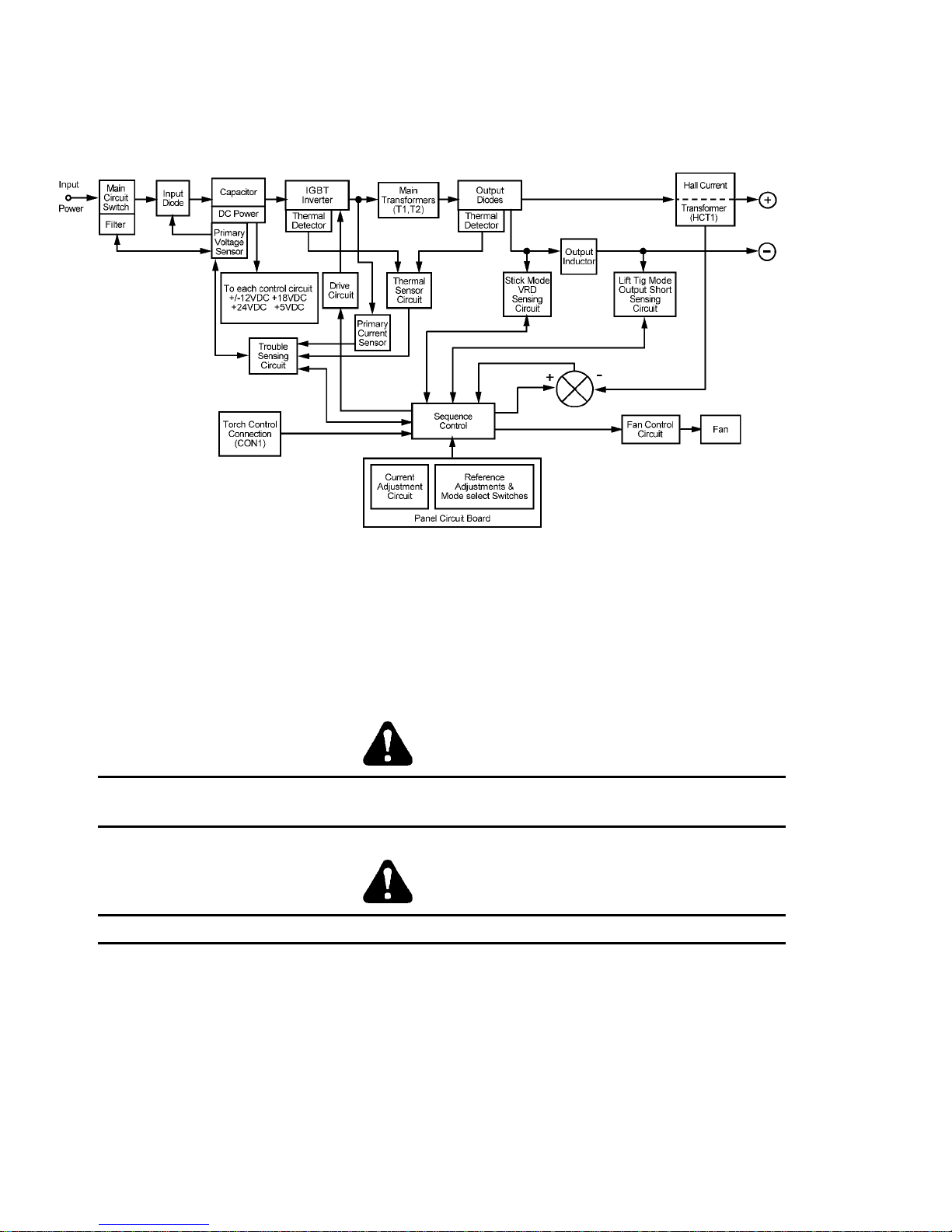
2.02 Functional Block Diagrams
Figure 2 illustrates the functional block diagram of the 250S-power supply.
Figure 2. 250S Model functional block diagram
2.03 Transporting Methods
These units are equipped with a handle for carrying purposes.
WARNING 1
ELECTRIC SHOCK can kill. DO NOT TOUCH live electrical parts. Disconnect input
power conductors from de-energized supply line before moving the welding power source.
WARNING 2
FALLING EQUIPMENT can cause serious personal injury and equipment damage.
Lift unit with handle on top of case.
Use handcart or similar device of adequate capacity.
If using a fork lift vehicle, place and secure unit on a proper skid before transporting.
14
Page 15

3.0 INSTALLATION RECOMMENDATIONS
3.01 Environment
The Pro-Lite 250S is desig ned for use i n ha zardou s env ironment s.
Examples of environments with increased hazardous environments are -
a. In locations in which freedom of movement is restricted, so that the operator is forced
to perform the work in a cramped (kneeling, sitting or lying) position with physical
contact with conductive parts;
b. In locations which are fully or partially limited by conductive elements, and in which
there is a high risk of unavoidable or accidental contact by the operator, or
c. In wet or damp hot locations where humidity or perspiration considerably reduces the
skin resistance of the human body and the insulation properties of accessories.
Environments with hazardous environments do not include places where electrically conductive
parts in the near vicinity of the operator, which can cause increased hazard, have been
insulated.
3.02 Location
Be sure to locate the welder according to the following guidelines:
• In areas, free from moisture and
dust.
• In areas, free from oil, steam and
corrosive gases.
• In areas, not exposed to direct
sunlight or rain.
• Ambient temperature between 0 degrees
C to 40 degrees C.
• In areas, not subjected to abnormal
vibration or shock.
• Place at a distance of 12” (304.79mm) or
more from walls or similar that could
restrict natural airflow for cooling.
WARNING 3
Thermal Arc advises that this equipment be electrically connected by a qualified
electrician.
15
Page 16

3.03 Electrical Input Connections
WARNING 4
ELECTRIC SHOCK can kill; SIGNIFICANT DC VOLTAGE is present after removal of
input power.
DO NOT TOUCH live electrical parts.
SHUT DOWN welding power source, disconnect input power employing lockout/tagging
procedures. Lockout/tagging procedures consist of padlocking line disconnect switch in open
position, removing fuses from fuse box, or shutting off and red-tagging circuit breaker or other
disconnecting device.
3.03.01 Electrical Input Requirements
Operate the welding power source from a single/three-phase 50/60 Hz, AC power supply. The
input voltage must match one of the electrical input voltages shown on the input data label on the
unit nameplate. Contact the local electric utility for information about the type of electrical
service available, how proper connections should be made, and inspection required.
The line disconnect switch provides a safe and convenient means to completely remove all
electrical power from the welding power supply whenever necessary to inspect or service the unit.
Note 2
These units are equipped with a three-conductor with earth power cable that is connected
at the welding power source end for single and three phase electrical input power.
Do not connect an input (WHITE or BLACK or RED) conductor to the ground terminal.
Do not connect the ground (GREEN) conductor to an input line terminal.
Refer to figure 3 and:
1. Connect end of ground (GREEN) conductor to a suitable ground. Use a grounding method that
complies with all applicable electrical codes.
2. Connect ends of line 1 (BLACK) and line 2 (WHITE) and line 3 (RED) input conductors to a deenergized line disconnect switch.
3. Use Table 1 and Table 2 as a guide to select line fuses for the disconnect switch.
Note 3
For Single-Phase operation connect the GREEN, BLACK and WHITE input conductors.
Insolate the RED Conductor, it is not used for Single-phase operation.
16
Page 17
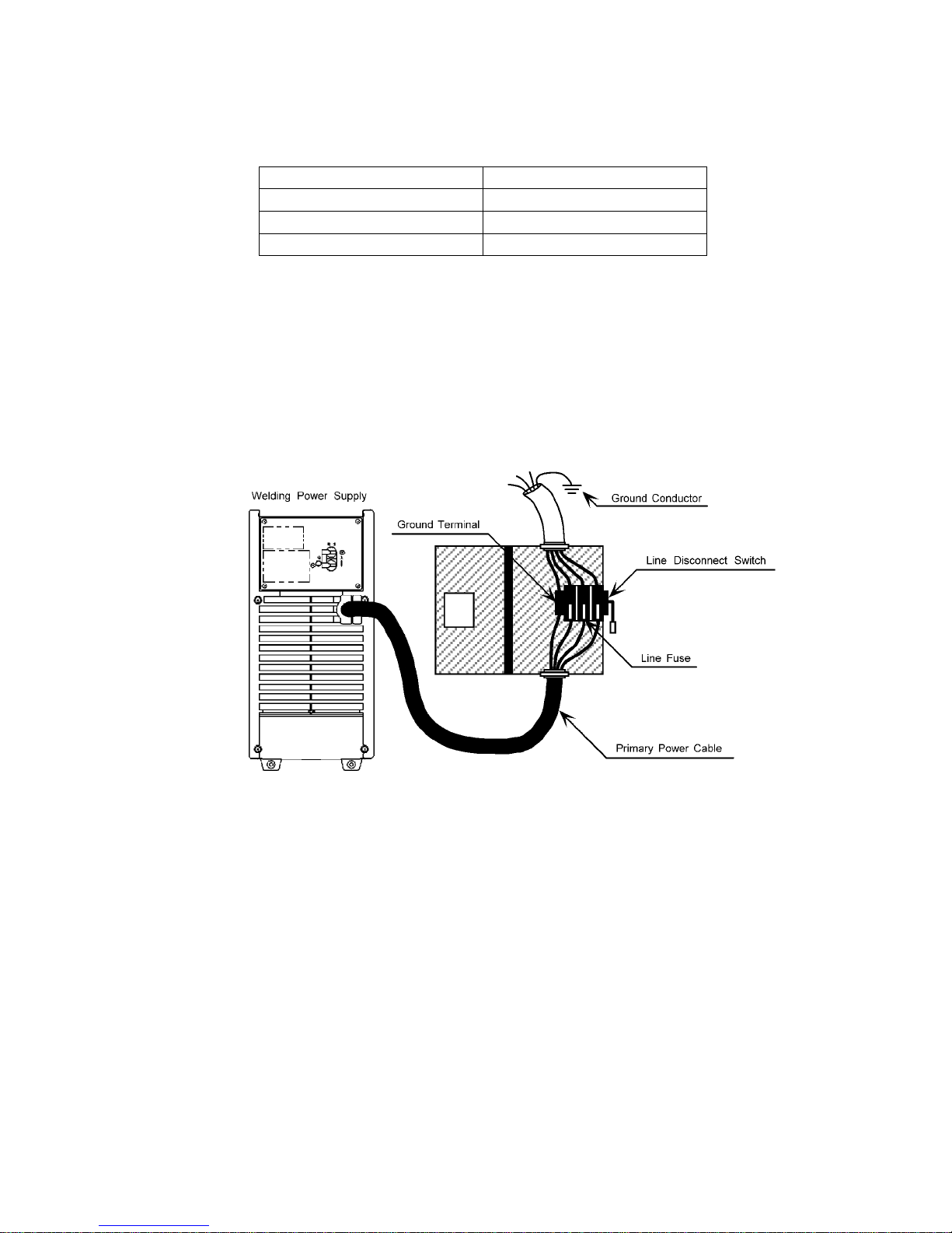
Input Voltage Fuse Size
208 75
230 70
460 20
Table 1 Electrical Input Connections
NOTE: Fuse size is based on not more than 200 percent of the rated input amperage of the welding
power source (Based on Article 630, National Electrical Code).
Figure 3. Electrical Input Connections
17
Page 18

3.03.02 Input Power
Each unit incorporates an INRUSH circuit and input voltage sensing circuit. When the MAIN
CIRCUIT BREAKER is turned on, the inrush circuit provides a pre-charging of the input
capacitors. SCR’s in the Power Control Assembly (PCA) will turn on after the input capacitors
have charged to full operating voltage (after approximately 5 seconds).
Note 4
Note the available input power. Damage to the PCA could occur if 575VAC or higher is
applied.
The following 208-230/460V Primary Current recommendations are required to obtain the maximum
welding current and d uty cycle from this welding equipment:
Model
PRO-LITE 250S
Table 2 – 230/460V Primary Current Circuit sizes to achieve maximum current
Primary Supply
Lead Size
8/4 AWG minimum
(Factory Fitted)
8/3 AWG minimum
Minimum Primary
Current Circuit Size
(Vin/Phase/Amps)
208/3/24 230/3/21 -
460/3/11
208/3/35
230/3/32
460/3/16
208/1/51 230/1/46
208/1/75
230/1/68
Current
& Duty Cycle
TIG STICK
250A @ 40%
-
250A @ 40%
250A @ 40%
-
250A @ 40%
18
Page 19

3.03.03 High Frequency Introduction
The importance of correct installation of high frequency welding equipment cannot be overemphasized. Interference due to high frequency initiated or stabilized arc is almost invariably
traced to improper installation. The following information is intended as a guide for personnel
installing high frequency welding machi nes.
Warning
Explosives
The high frequency section of this machine has an output similar to a radio transmitter. The
machine should NOT be used in the vicinity of blasting operations due to the danger of
premature firing.
Computers
It is also possible that operation close to computer installations may cause computer
malfunction.
3.03.04 High Frequency Interference
Interference may be transmitted by a high frequency initiated or stabilized arc-welding
machine in the following way s:
Direct Radiation
Radiation from the machine can occur if the case is metal and is not properly grounded. It
can occur through apertures such as open access panels. The shielding of the high frequency
unit in the Power Source w ill preve nt d irect radiat ion if t he equipmen t is pr operly grounded.
Transmission via the Supply Lead
Without adequate shielding and filtering, high frequency energy may be fed to the wiring
within the installation (mains) b y direct coupling. The energy is then transmitted by both
radiation and conduction. A dequate sh ield ing and fil ter ing is provided in the Power S ource.
Radiation from Welding Leads
Radiated interference from welding leads, although pronounced in the vicinity of the leads,
diminishes rapidly with distance. Keeping leads as short as possible will minimize this type
of interference. Looping and sus pending of leads sho uld be avo ided where pos sib le.
Re-radiation from Unearthed Metallic Objects
A major factor contributing to interference is re-radiation from unearthed metallic objects
close to the welding leads. Effective grounding of such objects will prevent re-radiation in
most cases.
19
Page 20

3.04 Specifications
Parameter 250S
Rated Output
Amperes
Volts
Duty Cycle
208-230/460VAC
250
30
40%
Duty Cycle 250A / 30V @ 40%
190A / 27V @ 60%
Output Current 5 – 250 Amps
Range
Open Circuit Voltage 69V
Dimensions
Width
Height
Length
7.08” (180mm)
14.17” (360mm)
16.54” (420mm)
Weight 39.68 lb. 18 kg
Output @ Rated Load
Output Amperes
Output Volts
Duty Cycle
KVA
KW
Three-phase Single-phase
250A 250A
30V 30V
40% 40%
12.5 15.7
9.4 9.4
Output @ No Load
KVA
KW
Input Volts Three Phase
0.5 0.5
0.13 0.13
Amperage Draw @ Rated Load
208V
230V
460V
Input Volts Single Phase
208V
230V
460V
35
32
16
75
68
-
No Load
1.3
1.1
0.7
2.2
1.6
-
Thermal Arc continuously strives to produce the best product possible and therefore reserves the right to change, improve or revise the
specifications or design of this or any product wi thout prior notice. Such updates or changes do not entitle the bu yer of eq uipment
previously sold or shipped to the corresponding changes, updates, improvements or replacement of such items.
20
Page 21

3.05 Duty Cycle
The duty cycle of a welding power source is the percentage of a ten (10) minute period that it can
be operated at a given output without causing overheating and damage to the unit. If the welding
amperes decrease, the duty cycle increases. If the welding amperes are increased beyond the
rated output, the duty cycle will decrease.
WARNING 5
Exceeding the duty cycle ratings will cause the thermal overload protection circuit to
become energized and shut down the output until the unit has cooled to normal operating
temperature.
CAUTION 1
Continually exceeding the duty cycle rat ings can cause damage to the welding power
source and will void the manufactures warranty.
NOTE 5
Due to variations that can occur in manufactured products, claimed performance, voltages, ratings,
all capacities, measurements, dimensions and weights quoted are approximate only. Achievable
capacities and ratings in use and operation will depend upon correct installation, use, applications,
maintenance and service.
21
Page 22

PAGE LEFT INTENTIONALLY BLANK
22
Page 23
4.0 OPERATOR CONTROLS
4.01 Pro-Lite 250S Controls
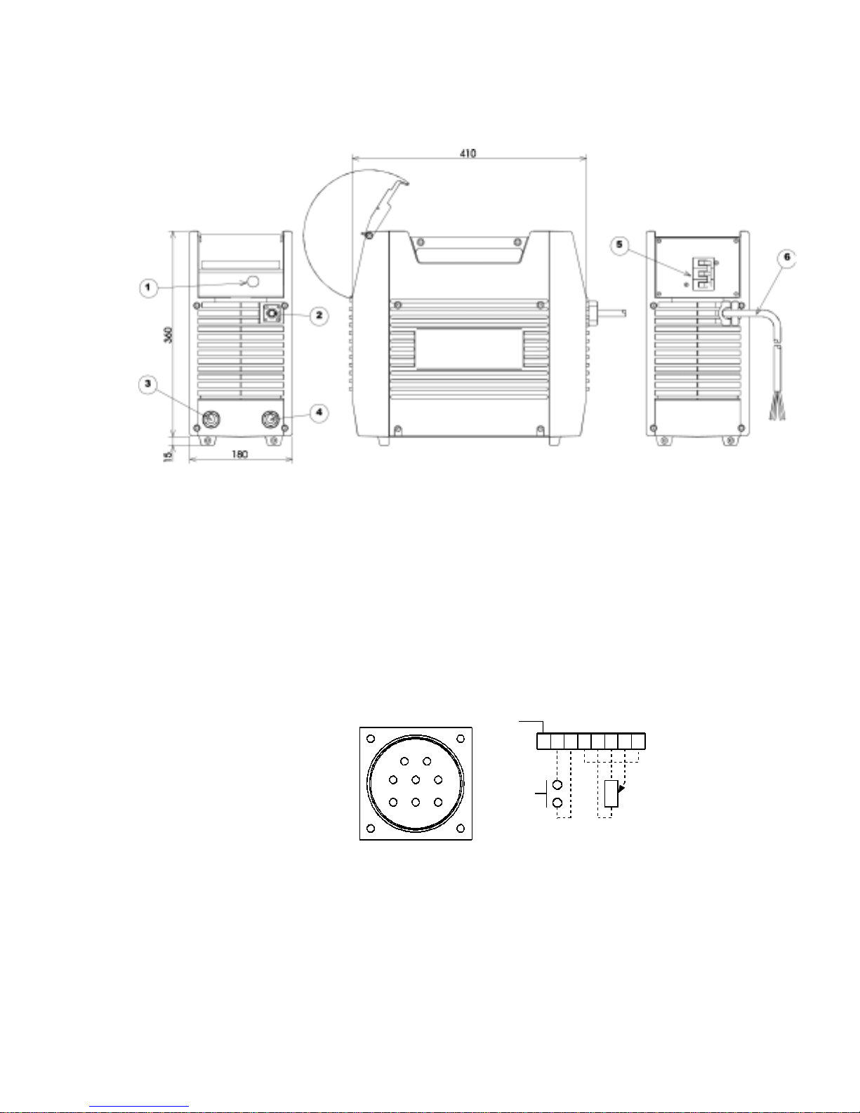
Figure 4. – Pro-Lite 250S Power Source
1 Control Knob
This control sets the selected weld parameter, rotating it clockwise increases the parameter
and is indicated on the digital meter. Pushing the knob in previews the actual welding
voltage while welding.
2 Remote Control Socket
The 8 pin Remote Control S ocke t i s use d t o connec t remo te current con trol devices to the
welding Power Source. To make connect ion s, a lig n keyway, insert p lug, and rota te threaded
collar fully cloc kwise.
Gnd.
21
543
876
Front view of 8-Socket Receptacle
23
12345678
5k Ohms
Page 24
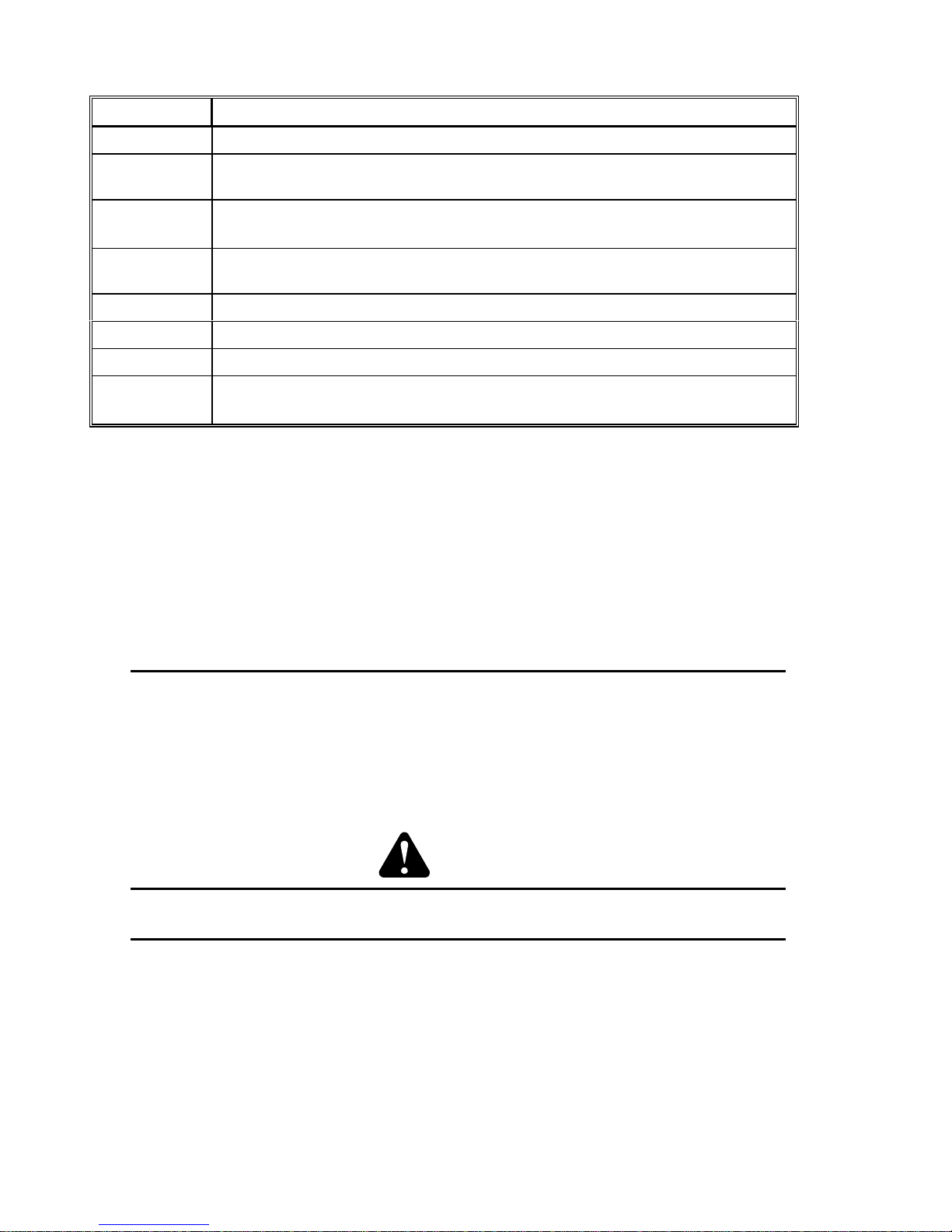
Socket Pin Functio n
1 Earth (Ground)
2
Torch Switch Input (24V) to energ ize we ld curren t.
(connect pins 2 & 3 to turn on wel ding current)
3
Torch Switch Input (0V) to e nergize weld current
(connect pins 2 & 3 to turn on wel ding current)
4
Connect pin 4 to pin 8 to instruct machine that a remote current control device
is connected (12V DC supply)
5 5k ohm (maximum) connection to 5k ohm rem ote co ntro l po tent io meter
6 Zero ohm (minimum) connection to 5k ohm re mote control potentiometer
7 Wiper arm connection to 5 k oh m r em ote control potentiome ter
8 Connect pin 4 to pin 8 to instruct machine that a remote current control device
is connected (0V)
3 Positive Terminal
Welding current flows from the Power Source via heavy duty Dinse type terminal. It is
essential, however, that the male plug is inserted and turned securely to achieve a sound
electrical connection.
4 Negative Terminal
Welding current flows from the Power Source via heavy duty Dinse type terminal. It is
essential, however, that the male plug is inserted and turned securely to achieve a sound
electrical connection.
CAUTION 2
Loose welding terminal connections can cause overheating and result in the male plug
being fused in the bayonet terminal.
5 ON/OFF Switch
This switch connects the Primary suppl y voltage to the inverter when in the ON position.
This enables the Power Sup ply.
WARNING 6
When the welder is connected to the Primary supply voltage, the internal electrical
components maybe at primary potential with respect to earth.
6 Input Cable
The input cable connects the Primary supply voltag e to the eq uip ment.
SMART Logic Switch (Not Sho wn)
Manual slide switch mounted on the back panel selects for proper input voltage. If this slide
is not set to the position that matches the input voltage from the electrical source the Smart
Logic circuit will inhibit welding power source output. The digital meter will show primary
input error code.
24
Page 25
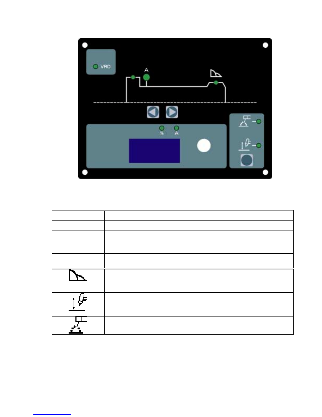
4.02 Weld Parameter Description
Figure 5. - Pro-Lite 250S Front Panel with Parameter Description
Parameter Description
This parameter operates in STICK weld mode and is used to improve
HOT START
the start characteristics for stick electrodes. e.g. low hydrogen
electrodes. It sets the peak start current on top of the (WELD) current.
Weld Current (Amperage)- sets the STICK and TIG WELD current.
A
ARC CONTROL - This parameter provides a suitable short circuit
current in STICK welding to improve electrode sticking and arc
stability.
LIFT TIG mode of operation. A remote control device is required for
use during LIFT TIG operation. See section 4.01, section 2 “Remote
Control Socket”, for complete details of the remote device.
STICK Mode of operation
Table 3 – Weld Parameter Descriptions
25
Page 26

4.03 Weld Parameters for Pro-Lite 250S
Weld Mode
Weld
Parameter
Parameter
Range
Factory
Setting
Incremental
Unit
STICK LIFT TIG
HOT START 0 to 70A 20A 1A Yes No
WELD CUR 5 to 250A 230V 80A 1A Yes Yes
ARC CONTROL 0 to 100% 10% 1% Yes No
4.04 Power Source Features
Feature Description
New Digital Control
Touch Panel Switches
Front Control Cover
Digital Meter
• Almost all welding parameters are adjustable
• Touch switches eliminate mechanical damage
• Protects front panel controls
• Displays selected weld parameter value
• Displays weld current when welding
• Displays weld current for 20 seconds after weld
has been completed
• A selected weld parameter value can be adjusted at
any time even while welding
Intelligent Fan Control
• The intelligent cooling system is designed to
reduce dust and foreign material build-up, whilst
providing optimum cooling.
• Fan speed reduces approximately 30 seconds after
machine is turned on
• Fan speed increases when internal components
reaches operating temperature
ON/OFF switch
Voltage Reduction Device (VRD)
Control Knob
• Primary voltage Supply ON/OFF switch located
on rear panel
Reduces the OCV when the power supply is not in
use. Eliminates the need for add on voltage reducers
and has no effect on arc starting.
• VRD fully complies to IEC 60974-1
• When Stick mode is selected the green VRD light
is ON when not welding and red when welding.
• When in TIG modes VRD is off.
• For the selected weld parameter, rotating the knob
clockwise increases the parameter
• Rotating the knob counterclockwise decreases the
parameter
• A selected weld parameter value can be adjusted at
any time even while welding
• Pushing the knob in displays actual arc voltage.
26
Page 27

Feature Description
Self Diagnosis Using Error Codes
• An error code is displayed on the Digital Meter
when a problem occurs with Primary supply
voltage or internal component problems. Refer to
troubleshooting guide.
27
Page 28
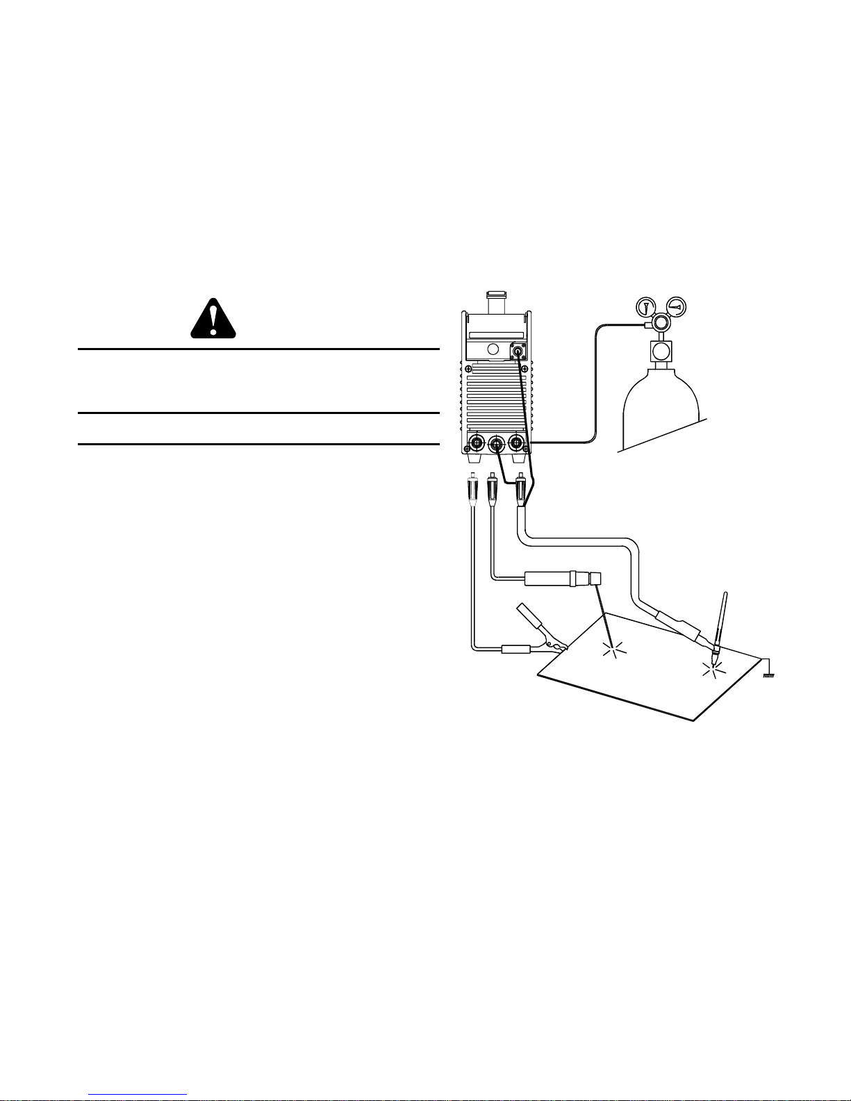
5.0 SET-UP FOR SMAW (STICK) AND GTAW (TI G )
Conventional operating procedures apply when using t he Welding Power Source, i.e. connect work
lead directly to work piece and electrode lead is used to hold electrode. Wide safety margins
provided by the coil design ensure that the Welding Power Source will withstand short-term
overload without adverse effects. The welding current range values should be used as a guide
only. Current delivered to the arc is dependent on the welding arc voltage, and as welding arc
voltage varies between different classes of electrodes, welding current at any one setting would
vary according to the type of electrode in use. The operator should use the welding current range
values as a guide, the n f ina l ly adjust the current se tting to suit the app lic ati on.
Figure 6. – 250S Set-up
WARNING 7
Before connecting the work clamp to the work and
inserting the electrode in the electrode holder make
sure the Primary power supply is switched off.
CAUTION 3
Remove any packaging material prior to use. Do
Remove any packaging material prior to use. Do
Remove any packaging material prior to use. DoRemove any packaging material prior to use. Do
not block the air vents at the front or rear or sides
not block the air vents at the front or rear or sides
not block the air vents at the front or rear or sidesnot block the air vents at the front or rear or sides
of the Welding Power Source.
of the Welding Power Source.
of the Welding Power Source.of the Welding Power Source.
28
Page 29
6.0 SEQUENCE OF OPERATION
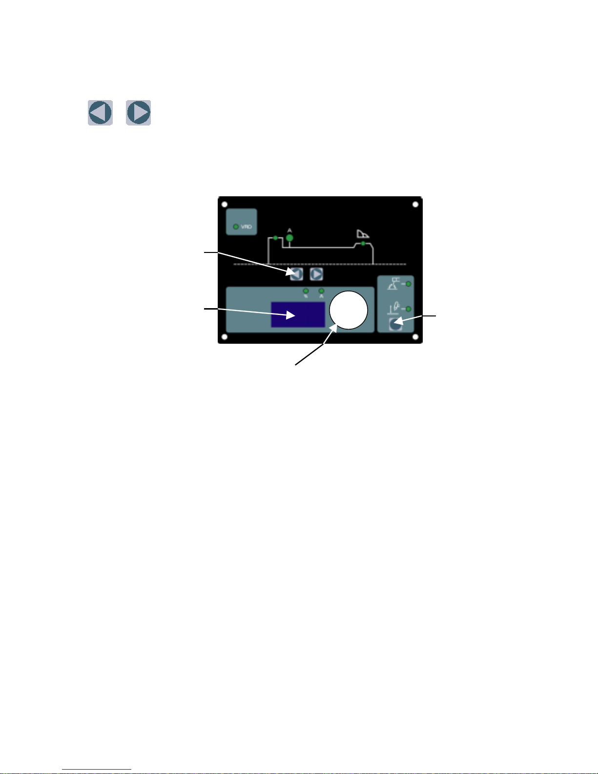
NOTE: Scroll Buttons are used to select the parameters to be set. The
LED’s show which function is being adjusted on the weld sequence graph.
Refer to Symbols Table located in the front of the manual for Symbol
descriptions.
1
2
4
3
Figure 7. - 250S Front Panel
1. Scroll Buttons – used to select the parameters to be set. The LED’s show which function is
being adjusted on the weld sequence graph.
2. Digital LED display – Welding amperage and parameter values are displayed in this window.
Internal warnings such as over temperature, low or high input voltage applied are signaled to the
operator by a warning sound and error message on the screen.
3. Control knob – allows the operator to adjust the output amperage within the entire range of the
power source also used to set each parameter value.
4. Process Button – This button selects between STICK or Lift TIG mode. A remote control device
is required for use during LIFT TIG operation. See section 4.01, section 2 “Remote Control
Socket”, for complete details of the remote device.
29
Page 30

6.01 Stick Welding
• Connect work lead to negative terminal
• Connect electrode lead to positive terminal
• Switch machine on
• Connect remote control device if required
Use the Scroll Button s t o m ove t o t he pa rame ter to be set . T he LED will show which
function is being adjusted on t he weld sequence g raph. Use the con trol kno b to adj us t each
parameter.
• Set HOT START
• Set WELD current
• Set Arc Contr ol
Commence welding
6.02 DC LIFT TIG Welding
• Connect work lead to positive terminal
• Connect TIG torc h to neg ative terminal
• Switch machine on
• Set weld curren t.
• Connect remote control device. A remote con trol device is required for use during LIFT
TIG operation. See section 4.01, secti on 2 “ Remote Contr ol Socket”, for c ompl e te details
of the remote device.
Use the Scroll Button s t o m ove t o t he pa rame ter to be set . T he LED will show which
function is being adjusted on t he weld sequence g raph. Use the con trol kno b to adj us t each
parameter.
• Set WELD current
Commence welding
30
Page 31

7.0 BASIC TIG WELDING GUIDE
7.01Electrode Polarity
Connect the TIG torch to the - / TORCH terminal and the work lead to the + / WORK
terminal for direct current straight po larity. Direct current straight polarity is the most widely
used polarity for DC TIG welding. It allows limited wear of the electrode since 70% of the
heat is concentrated at the work piece.
7.02 Tungsten Electrode Current Ranges
Electrode Diameter DC Current (Amps)
0.040” (1.0mm) 30 – 60
1/16” (1.6mm) 60 – 115
3/32” (2.4mm) 100 – 165
1/8” (3.2mm) 135 – 200
5/32” (4.0mm) 190 – 280
3/16” (4.8mm) 250 – 340
Table 4 – Current ranges for varies tungsten electrode sizes
7.03 Tungsten Electrode Types
Electrode Type
Welding Application Features
(Ground
Finish)
DC welding of mild steel,
Thoriated 2%
stainless steel and copper.
DC welding of mild steel,
Ceriated 2%
stainless steel, copper,
aluminium, magnesium and
their alloys
Excellent arc starting, Long
life, High current carrying
capacity.
Longer life, More stable arc,
Easier starting, Wider current
range, Narrower more
concentrated arc.
Table 5 – Tungsten electrode types
Color
Code
Red
Grey
31
Page 32
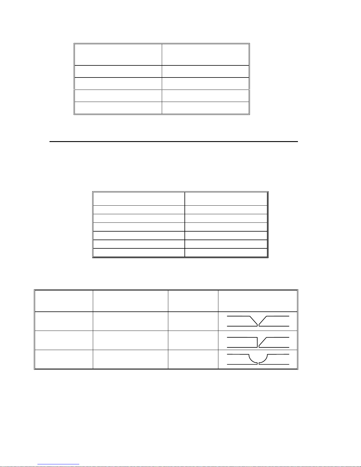
7.04 Guide for Selecting Filler Wire Diameter
Filler Wire Diameter DC Current Range
1/16” (1.6 mm) 20 - 90
3/32” (2.4 mm) 65 - 115
1/8” (3.2 mm) 100 - 165
3/16” (4.8 mm) 200-350
Table 6 – Filler wire selection guide
NOTE 6
The filler wire diameter specified in Table 6 is a guide only, other diameter wires may
be used according to the welding application.
7.05 Shielding Gas Selection
Alloy Shielding Gas
(Amps)
Aluminium & alloys Argon
Carbon Steel Argon
Stainless Steel Argon
Nickel Alloy Argon
Copper Argon
Titanium Argon
Table 7 – Shielding gas selection
7.06 TIG Welding Parameters for Low Carbon & Low Alloy Steel Pipe
Electrode Type &
Diameter
Thoriated 2%
3/32” (2.4 mm)
Thoriated 2%
3/32” (2.4 mm)
Thoriated 2%
3/32” (2.4 mm)
Current Range DC
Amperes
120 - 170 Yes
100 - 160 Yes
90 - 130 No
Filler Rod for
Root Pass
Joint Preparation
Table 8 – TIG welding parameters for low carbon & low alloy steel pipe
32
Page 33

7.07 Welding Parameters for Steel
Base Metal
Thickness
0.040”
1.0mm
0.045”
1.2mm
1/16”
1.6mm
1/8”
3.2mm
3/16”
4.8mm
¼”
6.4mm
DC Current
for Mild
Steel
35-45 20-30 Butt/Corner
40-50 25-35
45-55 30-45 Butt/Corner
50-60 35-50
60-70 40-60 Butt/Corner
70-90 50-70
80-100 65-85 Butt/Corner
90-115 90-110
115-135 100-125 Butt/Corner
140-165 125-150
160-175 135-160 Butt/Corner
170-200 160-180
DC Current
for Stainless
Steel
Tungsten
Electrode
Diameter
0.040”
1.0mm
0.040”
1.0mm
1/16”
1.6mm
1/16”
1.6mm
3/32”
2.4mm
1/8”
3.2mm
Filler Rod
Diameter
(if required)
1/16”
1.6mm
1/16”
1.6mm
1/16”
1.6mm
3/32”
2.4mm
1/8”
3.2mm
5/32”
4.0mm
Argon Gas
Flow Rate
Liters/min
5-7
5-7
7
7
10
10
Joint Type
Lap/ Fillet
Lap/ Fillet
Lap/ Fillet
Lap/ Fillet
Lap/ Fillet
Lap/ Fillet
Table 9 – DC TIG welding parameters
33
Page 34

8.0 BASIC ARC WELDING GUIDE
8.01Electrode Polarity
Stick electrodes are generally connected to the ‘+’ terminal and the work lead to the ‘−’
terminal but if in doubt consu lt the electrode manufacturers literature.
8.02 Effects of Stick Welding Various Materials
High tensile and alloy steels
The two most prominent effects of welding these steels are the formation of a hardened zone in
the weld area, and, if suitable precautions are not taken, the occurrence in this zone of under-bead
cracks. Hardened zone and under-bead cracks in the weld area may be reduced by using the
correct electrodes, preheating, using higher current settings, using larger electrodes sizes, short
runs for larger electrode deposits or tempering in a furnace.
Manganese steels
The effect on manganese steel of slow cooling from high temperatures is to embrittle it. For this
reason it is absolutely essential to keep manganese steel cool during welding by quenching after
each weld or skip welding to distribute the heat.
Cast Iron
Most types of cast iron, except white iron, are weldable. White iron, because of its extreme
brittleness, generally cracks when attempts are made to weld it. Trouble may also be experienced
when welding white-heart malleable, due to the poros ity caused by gas held in t his ty pe of iron.
Copper and alloys
The most important factor is the high rate of heat conductivity of copper, making preheating of
heavy sections necessary to give proper fusi on of wel d an d base meta l.
Types of Electrodes
Arc Welding electrodes are classified into a number of groups depending on their applications.
There are a great number of electrodes used for specialized industrial purposes which are not of
particular interest for everyda y general work. These include some low hydrogen types for high
tensile steel, cellulose types for welding large diameter pipes, etc. The range of electrodes dealt
with in this publica ti on w il l cove r the vast majority of applications like ly to be encountered; are all
easy to use and all will work on even the most basic of welding machines.
Metals being
joined
Mild steel 6013
Mild steel 7014 All positional electrode for use on
Cast iron 99% Nickel Suitable for joining all cast irons
Stainless steel 318L-16 High corrosion resistance. Ideal for
Electrode Comments
Ideal electrodes for all general
purpose work. Features include out
standing operator appeal, easy arc
starting and low spatter.
mild and galvanized steel furniture,
plates, fences, gates, pipes and tanks
etc. Especially suitable for verticaldown welding.
except white cast iron.
34
Page 35

Metals being
joined
Copper, Bronze,
Brass, etc.
High Alloy Steels,
Dissimilar Metals,
Crack Resistance.
All Hard-To-Weld
Jobs.
Electrode Comments
dairy work, etc. On stainless steels.
Bronze
5.7 ERCUSI-A
312-16 It will weld most problematical jobs
Easy to use electrode for marine
fittings, water taps and valves, water
trough float arms, etc. Also for
joining copper to steel and for bronze
overlays on steel shafts.
such as spring s, shafts, broken joins
mild steel to stainless and alloy
steels.
Not suitable for Aluminum.
Table 10 - Types of Electrodes
35
Page 36

PAGE LEFT INTENTIONALLY BLANK
36
Page 37

9.0 BASIC TROUBLESHOOTING
WARNING 8
There are extremely dangerous voltages and power levels present inside this product. Do
not attempt to open or repair unless you are an Accredited Thermal Arc Service Agent and
you have had training in power measurements and troubleshooting techniques.
If major complex subassemblies are faulty, then the Welding Power Source must be returned to an
Accredited Thermal Arc Service Agent for repair.
The basic level of troubleshooting is that which can be performed without special equipment or
knowledge.
9.01 TIG Welding Problems
Weld quality is dependent on the selection of the correct consumables, maintenance of
equipment and proper welding technique.
Description Possible Cause Remedy
1
Excessive bead
build-up or poor
penetration or poor
fusion at edges of
weld.
2 Weld bead too
wide and flat or
undercut at edges
of weld or
excessive burn
through
3 Weld bead too
small or
insufficient
penetration or
ripples in bead are
widely spaced
apart
4 Weld bead too
wide or excessive
bead build up or
excessive penetration in butt joint
Welding current is too low
Increase weld current and/or
faulty joint preparation
Welding current is too high Decrease weld current
Travel speed too fast Reduce travel speed
Travel speed too slow Increase travel speed
5
Uneven leg length
in fillet joint
Wrong placement of filler rod Re-position filler rod
37
Page 38

Description Possible Cause Remedy
6 Electrode melts
when arc is struck.
A Electrode is connected to the
‘+’ terminal.
BB
7 Dirty weld pool. A Electrode contaminated
through contact with work
piece or filler rod material.
B Gas contaminated with air. B Check gas lines for cuts and
8
Electrode melts or
oxidizes when an
A
No gas flowing to welding
region.
arc is struck.
B Torch is clogged with dust. B Clean torch
C Gas hose is cut. C Replace gas hose.
D Gas passage contains
impurities.
E Gas regulator turned off. E Turn on.
F Torch valve is turned off. F Turn on.
A Connect the electrode to the
‘−’ terminal.
A Clean the electrode by
grinding off the contaminates.
loose fitting or change gas
cylinder.
A
Check the gas lines for kinks
or breaks and gas cylinder
contents.
D Disconnect gas hose from
torch then raise gas pressure
and blow out impurities.
G The electrode is too small for
the welding current.
G Increase electrode diameter
or reduce the welding current.
9 Poor weld finish. Inadequate shielding gas. Increase gas flow or check
gas line for gas flow
problems.
10 Arc flutters during
TIG welding.
A Tungsten electrode is too
large for the welding current.
A Select the right size electrode.
Refer to Basic TIG Welding
guide.
B Absence of oxides in the
weld pool.
B Refer Basic TIG Welding
Guide for ways to reduce arc
flutter.
11 Welding arc can
not be established.
A Work clamp is not connected
to the work piece or the
work/torch leads are not
connected to the right
A Connect the work clamp to
the work piece or connect the
work/torch leads to the right
welding terminals.
welding terminals.
B Torch lead is disconnected. B
C
Gas flow incorrectly set,
cylinder empty or the torch
valve is off.
Connect it to the ‘−‘ terminal.
C
Select the right flow rate,
change cylinders or turn torch
valve on.
38
Page 39
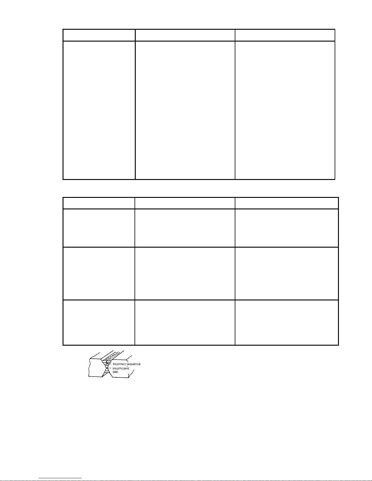
Description Possible Cause Remedy
12 Arc start is not
smooth.
A Tungsten electrode is too
large for the welding current.
B The wrong electrode is being
used for the welding job
C Gas flow rate is too high. C Select the correct rate for the
D
Incorrect shielding gas is
being used.
E Poor work clamp connection
to work piece.
9.02 Stick Welding Problems
Description Possible Cause Remedy
Gas pockets or
1
voids in weld metal
(Porosity).
A
Electrodes are damp.
B
Welding current is too high.
C
Surface impurities such as
oil, grease, paint, etc.
Crack occurring in
2
A
Rigidity of joint.
weld metal soon
after solidification
commences
3 A gap is left by
failure of the weld
B
Insufficient throat thickness.
C
Cooling rate is too high.
A
Welding current is too low.
B
Electrode too large for joint.
metal to fill the
root of the weld.
C
Insufficient gap.
D Incorrect sequence. D Use correct build-up sequence.
A Select the right size electrode.
Refer to Basic TIG Welding
Guide.
B Select the right electrode
type. Refer to Basic TIG
Welding Guide
welding job.
Refer to Basic TIG Welding
Guide.
D
Select the right shielding gas.
Refer to Basic TIG Welding
Guide.
E Improve connection to work
piece.
A
Dry electrodes before use.
B
Reduce welding current.
C
Clean joint before welding.
A
Redesign to relieve weld joint
of severe stresses or use crack
resistance electrodes.
B
Travel slightly slower to allow
greater build up in throat.
C
Preheat plate and cool slowly.
A
Increase welding current
B
Use smaller diameter
electrode.
C
Allow wider gap.
Figure 8 – Example of insufficient gap or incorrect
sequence
39
Page 40
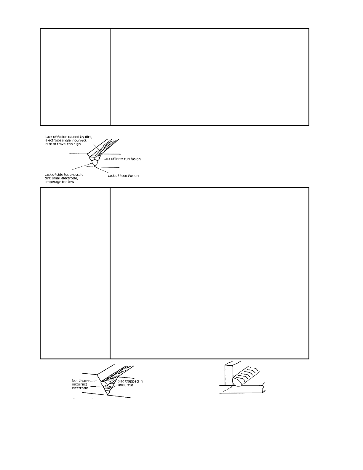
Portions of the
4
weld run do not
fuse to the surface
of the metal or
edge of the joint.
ABSmall electrodes used on
heavy cold plate.
Welding current is too low.AB
Use larger electrodes and preheat the plate.
Increase welding current
C Wrong electrode angle. C Adjust angle so the welding
arc is directed more into the
base metal
D
Travel speed of electrode is
too high.
D
Reduce travel speed of
electrode
E Scale or dirt on joint surface. E Clean surface before welding.
Figure 9 – Example of lack of fusion
Non-metallic parti-
5
cles are trapped in
the weld metal
(slag inclusion).
A Non-metallic particles may
be trapped in undercut from
previous run.
B
Joint preparation too
restricted.
C Irregular deposits allow slag
to be trapped.
D
Lack of penetration with slag
trapped beneath weld bead.
E Rust or mill scale is
preventing full fusion.
F Wrong electrode for position
in which welding is done.
A If bad undercut is present,
clean slag out and cover with a
run from a smaller diameter
electrode.
B
Allow for adequate
penetration and room for
cleaning out the slag.
C If very bad, chip or grind out
irregularities.
D
Use smaller electrode with
sufficient current to give
adequate penetration. Use
suitable tools to remove all
slag from corners.
E Clean joint before welding.
F Use electrodes designed for
position in which welding is
done, otherwise proper control
of slag is difficult.
Figure 10 – Examples of slag inclusion
40
Page 41

9.03 Power Source Problems
Description Possible Cause Remedy
1
The welding arc
cannot be
established
ABThe Primary supply voltage
has not been switched ON.
The Welding Power Source
switch is switched OFF.
ABSwitch ON the Primary supply
voltage.
Switch ON the Welding
Power Source.
2 Maximum output
welding current can
not be achieved
with nominal
Mains supply
voltage.
3 Welding current
reduces when
welding
4 No gas flow when
the torch trigger
switch is
depressed.
C Loose connections internally. C
Have an Accredited Thermal
Arc Service Agent repair the
connection.
Defective control circuit Have an Accredited Thermal
Arc Service Agent inspect
then repair the welder.
Poor work lead connection to
the work piece.
Ensure that the work lead has
a positive electrical
connection to the work piece.
ABGas hose is cut.
Gas passage contains
impurities.
ABReplace gas hose.
Disconnect gas hose from the
rear of Power Source then
raise gas pressure and blow
out impurities.
C Gas regulator turned off. C Turn gas regulator on.
41
Page 42

10.0 VOLTAGE REDUC TI ON DEVICE (VRD)
10.01 VRD Specification
Pro-Lite
Description
250S
VRD Open Circuit Voltage 15.3 to 19.8V Open circuit voltage between welding
terminals
VRD Resistance 148 to 193 ohms The required resistance between welding
terminals to turn O N the welding power
VRD Turn OFF Time 0.2 to 0. 3 secon ds The time taken to turn OFF the we ldi ng
power once the welding current has
stopped
10.02 VRD Maintenance
Routine inspection a nd te s ting (power sourc e)
An inspection of the power source, an insulation resistance test and an earth resistance test
shall b e carried out.
a) For transportable equipment, at least once every 3 months; and
b) For fixed equipment, at least once every 12 months.
Notes
The owners of the equipment shall keep a sui table record of the peri odic tes ts.
Note 7
A transportable power source is any equipment that is not permanently connected and
fixed in the position in which it is operated.
In addition to the above tests and specifically in relation to the VRD fitted to this machine,
the following periodic tests should also be conducted by an accredited Thermal Arc service
agent.
Description IEC 60974-1 Requirements
VRD Open Circuit Voltage L ess than 20 V; a t Vi n=208-230V or 460V
VRD Turn ON Resistance Less than 200 ohms
VRD Turn OFF Time Less than 0.3 seconds
If this equipment is used in a hazardous location or environments with a high risk of
electrocution then the above tests sh ould be carried ou t pri or t o enter ing thi s location.
42
Page 43

Weld current ceases.
Buzzer sounds constantly.
Fan operates at max speed.
E01 resets when TH1
decreases to 70ºC for about
30 seconds.
Let Power Source cool
down then keep within its
duty cycle.
Have an Accredited
Thermal Arc Service Agent
investigate
Unblock vents then let
Weld current ceases.
Buzzer sounds constantly.
Power Source cool down.
Let Power Source cool
down then keep within its
Fan operates at max speed.
E02 resets when TH1
duty cycle.
Have an Accredited
decreases to 70ºC for about
30 seconds.
Thermal Arc Service Agent
investigate
Weld current ceases.
Buzzer sounds constantly.
Switch machine off then on
to reset E03 error.
Unblock vents then let
Power Source cool down.
Reduce length of welding
arc.
Have an Accredited
Thermal Arc Service Agent
or a qualified electrician
check for low Mains
voltage.
A
The Welding Power
A
Source’s duty cycle has
been exceeded.
Fan ceases to operate.
B
B
C
Air flow is restricted by
vents being blocked
C
A
The Welding Power
A
Source’s duty cycle has
been exceeded.
Fan ceases to operate.
B
B
C
A
Air flow is restricted by
vents being blocked
C
Primary current is too high
A
because welding arc is too
B
43
long.
Mains supply voltage is
more than 10% below
nominal voltage
B
Description Possible Cause Remedy Remarks
E01 error code displayed
Temperature sensor TH1 (protects
IGBTs) is greater than 80ºC for
about 1 second
1
11.0 POWER SOURCE ERROR CODES
2 E02 error code displayed
Temperature sensor TH2 (protects
secondary diodes) is greater than
80ºC for about 1 second
Primary (input) current too high
3 E03 error code displayed
Page 44

Weld current ceases.
Buzzer sounds constantly.
Have an Accredited
Thermal Arc Service Agent
Error code E11
automatically will reset
or a qualified electrician
check the Primary voltage.
when the voltage reduces.
Weld current available.
Buzzer sounds
intermittently.
Have an Accredited
Thermal Arc Service Agent
or a qualified electrician
Error code E14
automatically will reset
check the Mains voltage.
when the voltage increases.
Weld current ceases.
Buzzer sounds constantly.
Have an Accredited
Thermal Arc Service Agent
Error code E12
automatically will reset
or a qualified electrician
check the Mains voltage
when the voltage increases.
Have an Accredited
No weld current is
available.
Buzzer sounds constantly.
Switch machine off.
No weld current is
available.
Buzzer sounds constantly.
Switch machine off.
Thermal Arc Service Agent
or a qualified electrician
check the primary cable &
fuses.
Have an Accredited
Thermal Arc Service Agent
or a qualified electrician
check the Mains voltage
Have an Accredited
Thermal Arc Service Agent
check connector plug on
input PCB
Primary supply voltage is
greater than the nominal
voltage plus 10%
Mains supply voltage is less
than the nominal operating
voltage less 10%.
A
Mains supply voltage is
down to a dangerously low
B
44
level.
When 3 phase machine is
first turned on with the
wrong Primary supply
(input) voltage connected
Link switch plug not
connected
Description Possible Cause Remedy Remarks
Over Primary supply (input)
voltage at primary capacitors is
exceeded for one second
4 E11 error code displayed
5 E14 error code displayed
Under mains supply (input) voltage
warning primary capacitors is
reduced for one second
Under mains supply (input) voltage
primary capacitors is reduced for
one second
6 E12 error code displayed
Wrong Primary supply (input)
7 E81 error code displayed
voltage connected
Link switch plug not connected
8 E82 error code displayed
Page 45

No weld current is
available.
Have an Accredited
Thermal Arc Service Agent
Buzzer sounds constantly.
Switch machine off then on
to reset E83 error.
Weld current ceases.
check connector plug on
input PCB and the Mains
voltage
Have an Accredited
Buzzer sounds constantly.
Switch machine off.
Thermal Arc Service Agent
check the control PCB
Weld current ceases.
Buzzer sounds constantly.
Have an Accredited
Thermal Arc Service Agent
Switch machine off.
check or replace the
temperature sensors.
Weld current ceases.
Buzzer sounds constantly.
Must switch machine off
then on to reset E99 error.
Turn on/off switch on.
Have an Accredited
Thermal Arc Service Agent
or a qualified electrician
check the Mains voltage and
fuses
The Primary supply (input)
voltage fluctuates and is not
stable.
Memory chip (EEPROM)
error
The Welding Power
Source’s temperature
A
sensors have malfunctioned.
Main on/off switch on
A
machine has been turned off
B
Mains supply (input)
voltage has been turned off
B
45
Description Possible Cause Remedy Remarks
CPU checks mains supply (input)
voltage when the on/off switch on
rear panel of machine is turned ON.
9 E83 error code displayed
10 E93 error code displayed
Memory chip (EEPROM) on
control PCB can not read/write
weld parameters
Temperature sensor TH1 for IGBTs
or sensor TH2 for secondary diodes
are open circuit
E99 error code displayed
Mains supply (input) voltage has
been turned off but control circuit
has power from the primary
capacitors
11 E94 error code displayed
12
Page 46

1 U0A706100 10-6627
1 U0A674900 10-6737
1 U0A722000 10-6738
46
Assembly)
12.0 PARTS LIST
DWG. No. Description Type & Rating QTY. Code No. Order No.
C1 Capacitor ECQE12104MZ DC1250V 0.1uF 1 42422137100 10-2270
CON1 Remote Socket 206433-1 8P (with Wiring
D1 Diode DFA75BA160 1 454170160 10-6735
(with Insulation Sheet EBA501500)
with Thunder Label
D2 Diode DBA200UA40 1 4582A0040 10-6687
D3 Diode DBA200UA40 1 4582A0040 10-6687
D4 Diode DBA200UA40 1 4582A0040 10-6687
D5 Diode DBA200UA40 1 4582A0040 10-6687
FAN1 Fan 109E5724H507 DC 24V 16.8W 1 U0A733500 10-6839
FCH1 Inductor F2A719500 FCH 1 F2A719500 10-6736
HCT1 Current Sensor HC-TN200V4B15M 200A 4V 1 11251003000 10-5003
PCB1 Printed Circuit Board WK-4914 U02 MAIN_PCB
PCB2 Printed Circuit Board WK-4819 U01 DETECT PCB 1 P0A481901 10-6635
with Thunder Label
PCB3 Printed Circuit Board WK-4921 U02 CONNECT PCB 1 P0A492102 10-6636
PCB4 Printed Circuit Board WK-4915 U02 2ND DIODE
PCB5 Printed Circuit Board WK-5157 U03 TIG CONTROL 1 P0A515703 10-6845
PCB6 Printed Circuit Board WK-4920 U11 STICK 1 P0A492011 10-6739
PCB7 Printed Circuit Board WK-4917 U04 FILTER 480V 1 P0A491704 10-6740
PCB10 Printed Circuit Board WK-5019 U01 CAP PCB 1 P0A501901 10-6741
PCB11 Printed Circuit Board WK-4923 U01 B RELAY PCB 1 P0A492301 10-6742
Page 47

1 U0A705300 10-6642
(with WK-5012 U01)
1 U0A705300 10-6642
47
(with WK-5012 U01)
DWG. No. Description Type & Rating QTY Code No. Order No.
12.0 PARTS LIST Continued
Q1 Transistor CM100DUS12F-1 600V 100A
Q2 Transistor CM100DUS12F-1 600V 100A
S1 Switch DCP-103SR100C-480V 3P 1 25850003700 10-6857
S2 Switch SDKGA4-A-1-A 250V 5A 1 24704531400 10-5222
T1 Transformer F2A767200 250A MTR HV 1 F2A767200 10-6744
T2 Transformer F2A767200 250A MTR HV 1 F2A767200 10-6744
TH1, 2 Thermistor ERTA53D203 20K"/25ºC B=395 0K 1 U0A733300 10-6784
Page 48

Front Panel E0D005300 1 U0A722100 10-6648
Rear Panel E0D005500 1 U0A722200 10-6649
Side Panel E0D006100 2 E0D006100 10-6650
48
TRAK-BE35-70S 2 26999025900 10-6660
Front Control Cover J4B493400 1 J4B493400 10-6651
Rear Control Cover JDA173200 1 U0A722300 10-6745
Protection Cover E0C303200 1 E0C303200 10-6653
Encoder Cover EBA514400 1 EBA514400 10-6654
PCB Cover E1B537600 (with Caution Label) 1 U0A705600 10-6655
PCB Sheet EBA618000 For PCB11 1 EBA618000 10-6747
Name Label N 4A05 6000 2 N4A056000 10-6746
Side Label N4A009200 2 N4A009200 10-6657
Warning Label 1 N0B891300 1 N0B891300 10-5497
Warning Label 2 N0B476400 1 N0B476400 10-5496
Output Terminal Label N4A040300 1 N4A040300 10-6748
Output Terminal
(female)
Input Cable SOOW AWG8X4C L=3.4m 1 U0A722400 REF. ONLY
Input Cable Clamp EBA045800 1 EBA045800 10-6662
Heatsink E1B538500 1 E1B538500 10-6663
Heatsink E1B538600 1 E1B538600 10-6664
Knob 2621603 1 50990001600 10-6665
Knob Cap 3021104 1 50990000300 10-6666
Control Cover Sheet N0B882300 1 N0B882300 10-6749
Flat Cable EAA547301 1 EAA547301 10-6668
DWG. No. Description Type & Rating QTY Code No. Order No.
12.0 PARTS LIST Continued
Page 49

49
Post4(M4-M4) EBA431100 4 EBA431100 10-6670
Post5(M4-M4) EBA431200 8 EBA431200 10-6671
Post6(M5-M5) EBA431300 2 EBA431300 10-6672
Post7(M5-M5) EBA435900 1 EBA435900 10-6673
Post9(M5-M5) EBA491700 4 EBA491700 10-6750
Post11(M5-M5) EBA643600 3 EBA643600 10-6751
D2-5 Bus Bar EBA366300 1 EBA366300 10-6752
CC Bus Bar EBA707600 1 EBA707600 10-6753
S1 Bus Bar ECA321000 3 ECA321000 10-6868
Output Bus Bar1 EBA456400 1 EBA456400 10-6754
Output Bus Bar2 EBA456600 1 EBA456600 10-6755
Clip #74 NATURAL 4 606024220 10-5259
Transformer Chassis JCA903200 1 JCA903200 10-6678
Right Chassis J2C970700 1 J2C970700 10-6679
Left Chassis J2C970800 1 J2C970800 10-6680
Output Terminal (male) TRAK-SK50 2 26999025800 10-2020
Operating Manual K1A208600 250S 1 K1A208600 430429-506
Service Manual 430429-516
DWG. No. Description Type & Rating QTY Code No. Order No.
12.0 PARTS LIST Continued
Page 50
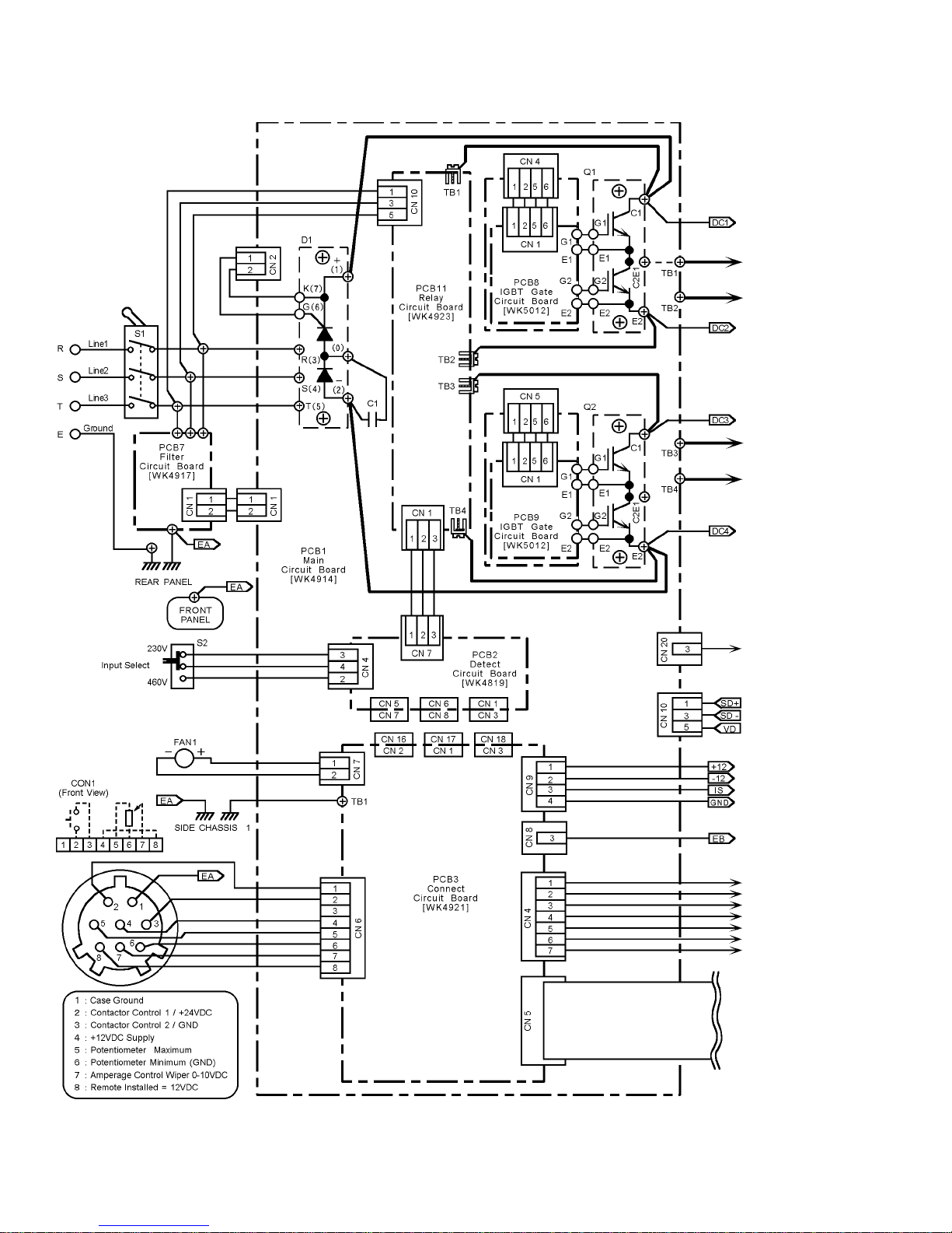
APPENDIX A - INTERCONNECT DIAGRAM
50
Page 51
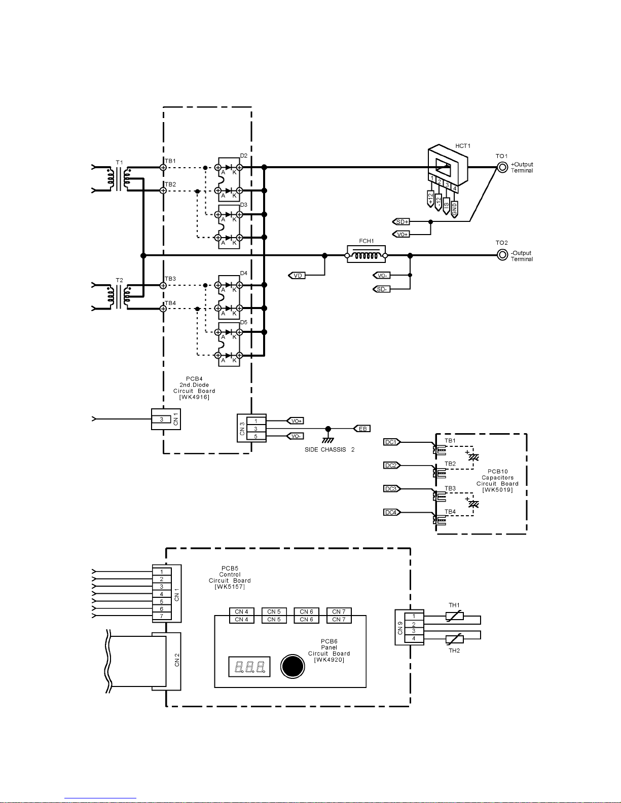
51
Page 52
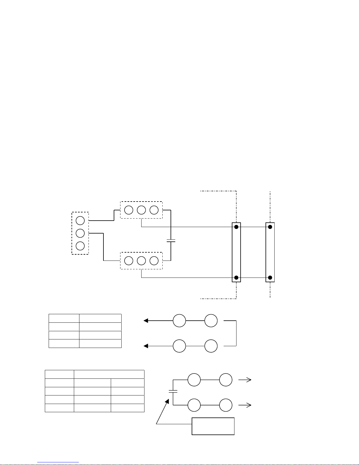
APPENDIX B - AUTOMATI ON
JUMPER SETTING FOR "OK–TO–MOVE". Models 250S/TS
Three jumpers (JP1, JP2 and JP3) are provided on PC Board WK-4921 for automation purposes. This
PCB is mounted horizontally on top of the unit just under the cover. This PCB can be accessed by
removing the side covers by loosening 4 screws on each the front and rear panel, then removing the 4
side panel screws as well as the 2 handle screws. Carefully pull the front and rear panels outward to
release and remove the side cover. Remove two plastic clips holding the PCB protective cover in place
and lift the sheet up and over the unit. The jumpers will be accessible on the top portion of the PCB.
See figure on next page for the location of the PCB.
All units are shipped from the factory with the jumpers set in position "A". This is for normal semiautomatic operation utilizing a remote device, such as a foot control. The 8-pin remote operates as
described earlier in this manual.
Placing all jumpers in position "B" would be primarily used for automation with an arc establish relay,
remote amperage and contactor. An arc-establish signal is located from pins 4 and 8 when in this mode.
Placing jumpers JP1 and JP2 in "B" position and jumper JP3 in "A" position would have the
configuration of an arc-establish signal and remote contactor, but the unit’s front panel would control
the amperage.
JP1
A COM B
JP3
WK-4921
B
COM
A
•
Set All "A" position : factory shipping
JP2
A COM B
POSITION
JP1 A
JP2 A
JP3 A
•
Use "OK TO MOVE signal"
POSITION
JP1 B B
JP2 B B
JP3 B A
A/V REMOTE PANEL
OK-TO-MOVE
RELAY
CN6 CON1
4 4
8
CN6 CON1
8
4 4
8
CN6 CON1
4 4
8 8
Remote : Short 4 to 8
Panel : Open
Max Load:
24V 50ma.
8
OK TO MOVE
RELAY
52
Page 53
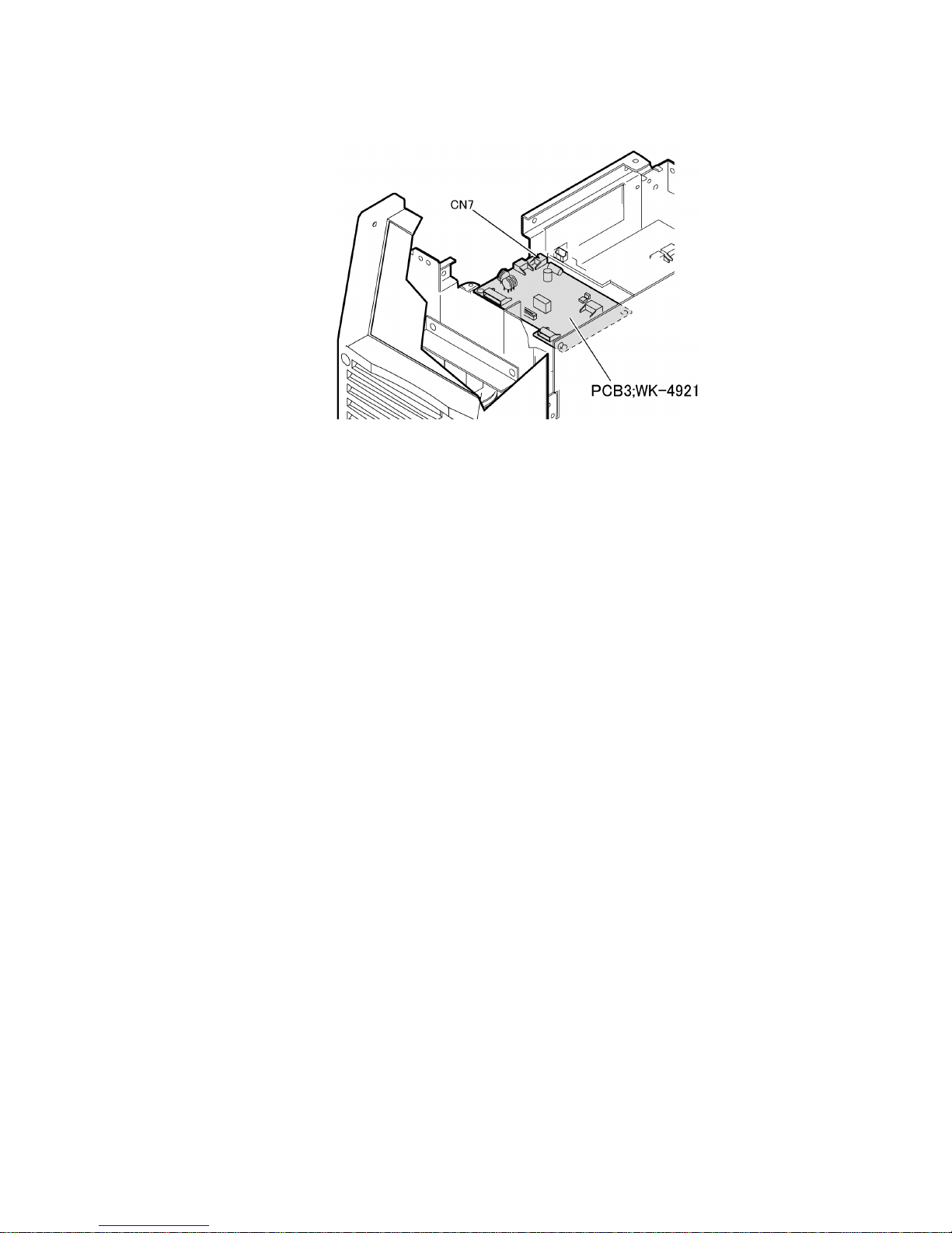
Figure 11 – Location of PCB WK-4921
53
 Loading...