

Page 1
A-11401
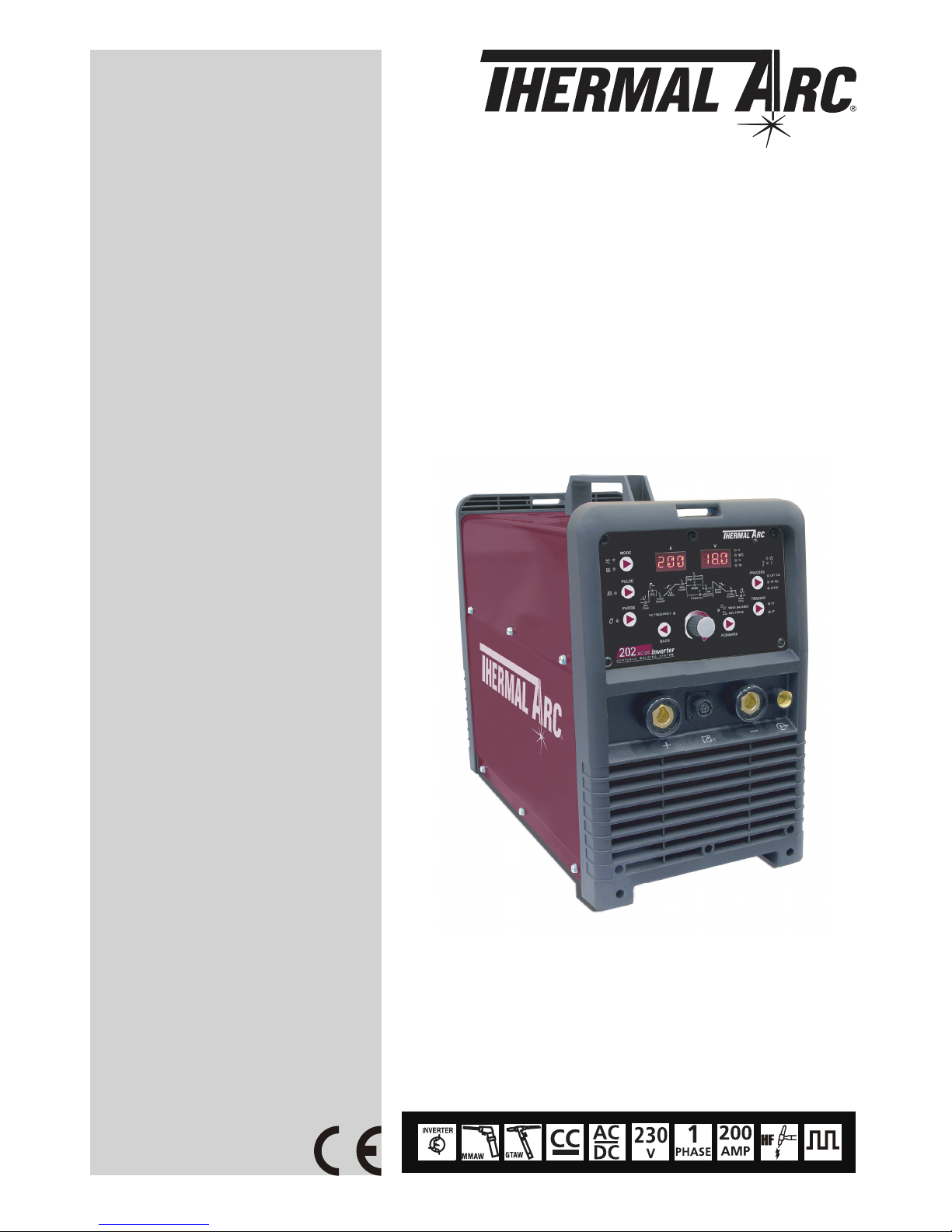
202 AC/DC
Operating Manual
Revision: AB Issue Date: August 6, 2012 Manual No.: 0-5239
Operating Features:
INVERTER
ARC WELDING MACHINE
Page 2
WE APPRECIATE YOUR BUSINESS!
Congratulations on your new Thermal Arc product. We are proud
to have you as our customer and will strive to provide you with
the best service and reliability in the industry. This product
is backed by our extensive warranty and world-wide service
network. To locate your nearest distributor or service agency call
+44 (0) 1257 261 755, or visit us on the web at www.Thermalarc.com.
This Operating Manual has been designed to instruct you on the correct
use and operation of your Thermal Arc product. Your satisfaction with
this product and its safe operation is our ultimate concern. Therefore
please take the time to read the entire manual, especially the Safety
Precautions. They will help you to avoid potential hazards that may
exist when working with this product.
We have made every effort to provide you with accurate instructions,
drawings, and photographs of the product(s) while writing this manual.
However errors do occur and we apologize if there are any contained
in this manual.
Due to our constant effort to bring you the best products, we may
make an improvement that does not get reflected in the manual. If you
are ever in doubt about what you see or read in this manual with the
product you received, then check for a newer version of the manual on
our website or contact our customer support for assistance.
YOU ARE IN GOOD COMPANY!
The Brand of Choice for Contractors and Fabricators Worldwide.
Thermal Arc is a Global Brand of Arc Welding Products for Victor
Technologies We manufacture and supply to major welding industry
sectors worldwide including; Manufacturing, Construction, Mining,
Automotive, Aerospace, Engineering, Rural and DIY/Hobbyist.
We distinguish ourselves from our competition through market-leading,
dependable products that have stood the test of time. We pride ourselves
on technical innovation, competitive prices, excellent delivery, superior
customer service and technical support, together with excellence in
sales and marketing expertise.
Above all, we are committed to develop technologically advanced
products to achieve a safer working environment within the welding
industry.
Page 3

!
WARNINGS
Read and understand this entire Manual and your employer’s safety practices before installing,
operating, or servicing the equipment.
While the information contained in this Manual represents the Manufacturer’s best judgement,
the Manufacturer assumes no liability for its use.
Welding Power Supply
Operating Manual Number 0-5239 for:
Thermal Arc 202 AC/DC Part Number W1006305
Thermal Arc 202 AC/DC Package Part Number W1006306
Published by:
Victor Technologies Europe
Europa Building
Chorley Industrial Park
Chorley, Lancaster,
England, PR6 7BX
www.victortechnologies.com
Copyright 2012 by
Victor Technologies, Inc.
All rights reserved.
Reproduction of this work, in whole or in part, without written permission of the
publisher is prohibited.
The publisher does not assume and hereby disclaims any liability to any party for any
loss or damage caused by any error or omission in this Manual, whether such error
results from negligence, accident, or any other cause.
Publication Date: July 9, 2012
Revision Date: August 6, 2012
Record the following information for Warranty purposes:
Where Purchased: ____________________________________
Purchase Date: ____________________________________
Equipment Serial #: ____________________________________
Page 4

TABLE OF CONTENTS
SECTION 1:
SAFETY INSTRUCTIONS AND WARNINGS ....................................................... 1-1
1.01 Arc Welding Hazards ....................................................................................... 1-1
1.02 Principal Safety Standards .............................................................................. 1-5
1.03 Symbol Chart .................................................................................................. 1-6
1.04 Declaration Of Conformity .............................................................................. 1-7
SECTION 2:
INTRODUCTION ..................................................................................... 2-1
2.01 How To Use This Manual ................................................................................ 2-1
2.02 Equipment Identification ................................................................................. 2-1
2.03 Receipt of Equipment ...................................................................................... 2-1
2.04 Description ..................................................................................................... 2-2
2.05 User Responsibility ......................................................................................... 2-2
2.06 Transporting Methods ..................................................................................... 2-2
2.07 Packaged Items .............................................................................................. 2-2
2.08 Specification .................................................................................................. 2-3
2.09 Duty Cycle ....................................................................................................... 2-4
2.10 Optional Accessories ...................................................................................... 2-5
SECTION 3:
INSTALLATION, OPERATION AND SETUP ........................................................ 3-1
3.01 Environment ................................................................................................... 3-1
3.02 Location .......................................................................................................... 3-1
3.03 Ventilation ....................................................................................................... 3-1
3.04 Mains Supply Voltage Requirements .............................................................. 3-1
3.05 High Frequency Introduction .......................................................................... 3-2
3.06 High Frequency Interference ........................................................................... 3-2
3.07 Electromagnetic Compatibility ........................................................................ 3-2
3.08 202 AC/DC Power Source Controls, Indicators and Features .......................... 3-4
3.09 202 AC/DC - STICK Programming Mode ........................................................ 3-8
3.10 202 AC/DC – LIFT TIG and HF TIG Programming Mode .............................. 3-10
3.11 Short Circuit Protection While Welding ......................................................... 3-13
3.12 Victor Regulator ............................................................................................ 3-13
3.13 Setup for TIG (GTAW) Welding ..................................................................... 3-16
3.14 Setup for STICK (MMA) Welding ................................................................ 3-18
Page 5

TABLE OF CONTENTS
SECTION 4:
BASIC WELDING GUIDE ............................................................................ 4-1
4.01 Stick (MMA) Basic Welding Technique ........................................................... 4-1
4.02 Stick (MMA) Welding Troubleshooting ........................................................... 4-9
4.03 TIG (GTAW) Basic Welding Technique .......................................................... 4-11
4.04 TIG (GTAW) Welding Problems ..................................................................... 4-13
SECTION 5:
POWER SOURCE PROBLEMS AND ROUTINE SERVICE REQUIREMENTS .................... 5-1
5.01 Basic Troubleshooting .................................................................................... 5-1
5.02 Power Source Problems ................................................................................. 5-1
5.03 Routine Service and Calibration Requirements ............................................... 5-2
5.04 Cleaning the Welding Power Source ............................................................... 5-4
SECTION 6:
KEY SPARE PARTS ................................................................................... 6-1
6.01 Power Source ................................................................................................. 6-1
APPENDIX: CIRCUIT DIAGRAM
THERMAL ARC - LIMITED WARRANTY TERMS
TERMS OF WARRANTY – JANUARY 2012
Page 6

Page 7
SAFETY INSTRUCTIONS 202 AC/DC
Manual 0-5239 1-1 SAFETY INSTRUCTIONS AND WARNINGS
1.01 Arc Welding Hazards
WARNING
ELECTRIC SHOCK can kill.
Touching live electrical parts can cause
fatal shocks or severe burns. The electrode
and work circuit is electrically live when
ever the output is on. The input power circuit and machine internal circuits are also
live when power is on. In semi-automatic
or automatic wire welding, the wire, wire
reel, drive roll housing, and all metal parts
touching the welding wire are electrically
live. Incorrectly installed or improperly
grounded equipment is a hazard.
1. Do not touch live electrical parts.
2. Wear dry, hole-free insulating gloves and body
protection.
3. Insulate yourself from work and ground using dry
insulating mats or covers.
4. Disconnect input power or stop engine before
installing or servicing this equipment. Lock input
power disconnect switch open, or remove line
fuses so power cannot be turned on accidentally.
5. Properly install and ground this equipment
according to its Owner’s Manual and national,
state, and local codes.
6. Turn OFF all equipment when not in use.
Disconnect power to equipment if it will be left
unattended or out of service.
7. Use fully insulated electrode holders. Never dip
holder in water to cool it or lay it down on the
ground or the work surface. Do not touch holders
connected to two welding machines at the same
time or touch other people with the holder or
electrode.
8. Do not use worn, damaged, undersized, or poorly
spliced cables.
9. Do not wrap cables around your body.
10. Ground the workpiece to a good electrical (earth)
ground.
11. Do not touch electrode while in contact with the
work (ground) circuit.
12. Use only well-maintained equipment. Repair or
replace damaged parts at once.
13. In confined spaces or damp locations, do not use
a welder with AC output unless it is equipped with
a voltage reducer. Use equipment with DC output.
14. Wear a safety harness to prevent falling if working
above floor level.
15. Keep all panels and covers securely in place.
SECTION 1:
SAFETY INSTRUCTIONS AND WARNINGS
!
WARNING
PROTECT YOURSELF AND OTHERS FROM POSSIBLE SERIOUS INJURY OR DEATH. KEEP CHILDREN
AWAY. PACEMAKER WEARERS KEEP AWAY UNTIL CONSULTING YOUR DOCTOR. DO NOT LOSE THESE
INSTRUCTIONS. READ OPERATING/INSTRUCTION MANUAL BEFORE INSTALLING, OPERATING OR
SERVICING THIS EQUIPMENT.
Welding products and welding processes can cause serious injury or death, or damage to other equipment or
property, if the operator does not strictly observe all safety rules and take precautionary actions.
Safe practices have developed from past experience in the use of welding and cutting. These practices must be
learned through study and training before using this equipment. Some of these practices apply to equipment
connected to power lines; other practices apply to engine driven equipment. Anyone not having extensive
training in welding and cutting practices should not attempt to weld.
Safe practices are outlined in the European Standard EN60974-1 entitled: Safety in welding and allied processes
Part 2: Electrical. This publication and other guides to what you should learn before operating this equipment
are listed at the end of these safety precautions. HAVE ALL INSTALLATION, OPERATION, MAINTENANCE,
AND REPAIR WORK PERFORMED ONLY BY QUALIFIED PEOPLE.
Page 8

202 AC/DC SAFETY INSTRUCTIONS
SAFETY INSTRUCTIONS AND WARNINGS 1-2 Manual 0-5239
WARNING
ARC RAYS can burn eyes and skin; NOISE
can damage hearing. Arc rays from the
welding process produce intense heat and
strong ultraviolet rays that can burn eyes
and skin. Noise from some processes can
damage hearing.
1. Wear a welding helmet fitted with a proper shade
of filter (see ANSI Z49.1 listed in Safety Standards)
to protect your face and eyes when welding or
watching.
2. Wear approved safety glasses. Side shields
recommended.
3. Use protective screens or barriers to protect others
from flash and glare; warn others not to watch the
arc.
4. Wear protective clothing made from durable,
flame-resistant material (wool and leather) and
foot protection.
5. Use approved ear plugs or ear muffs if noise level
is high.
6. Never wear contact lenses while welding.
AWS F2.2:2001 (R2010), Adapted with permission of the American Welding Society (AWS), Miami, Florida
Guide for Shade Numbers
Process
Electrode Size in.
(mm)
Arc Current
(Amperes)
Minimum
Protective
Shade
Suggested*
Shade No.
(Comfort)
Shielded Metal Arc Welding
(SMAW)
Less than 3/32 (2.4)
3/32-5/32 (2.4-4.0)
5/32-1/4 (4.0-6.4)
More than 1/4 (6.4)
Less than 60
60-160
160-250
250-550
7
8
10
11
10
12
14
Gas Metal Arc Welding (GMAW)
and Flux Cored Arc Welding
(FCAW)
Less than 60
60-160
160-250
250-550
7
10
10
10
11
12
14
Gas Tungsten arc Welding
(GTAW)
Less than 50
50-150
150-500
8
8
10
10
12
14
Air Carbon Arc Cutting (CAC-A)
(Light)
(Heavy)
Less than
500
500-1000
10
11
12
14
Plasma Arc Welding (PAW)
Less than 20
20-100
100-400
400-800
6
8
10
11
6 to 8
10
12
14
Plasma Arc Cutting (PAC)
Less than 20
20-40
40-60
60-80
80-300
300-400
400-800
4
5
6
8
8
9
10
4
5
6
8
9
12
14
* As a rule of thumb, start with a shade that is too dark to see the weld zone. Then go to a lighter
shade which gives sufficient view of the weld zone without going below the minimum. In oxyfuel gas
welding, cutting, or brazing where the torch and/or the flux produces a high yellow light, it is desirable
to use a filter lens that absorbs the yellow or sodium line of the visible light spectrum.
Page 9
SAFETY INSTRUCTIONS 202 AC/DC
Manual 0-5239 1-3 SAFETY INSTRUCTIONS AND WARNINGS
WARNING
FUMES AND GASES can be hazardous to
your health.
Welding produces fumes and gases.
Breathing these fumes and gases can be
hazardous to your health.
1. Keep your head out of the fumes. Do not breathe
the fumes.
2. If inside, ventilate the area and/or use exhaust at
the arc to remove welding fumes and gases.
3. If ventilation is poor, use an approved air-supplied
respirator.
4. Read the Material Safety Data Sheets (MSDSs)
and the manufacturer’s instruction for metals,
consumables, coatings, and cleaners.
5. Work in a confined space only if it is well ventilated,
or while wearing an air-supplied respirator.
Shielding gases used for welding can displace air
causing injury or death. Be sure the breathing air
is safe.
6. Do not weld in locations near degreasing, cleaning,
or spraying operations. The heat and rays of the
arc can react with vapours to form highly toxic
and irritating gases.
7. Do not weld on coated metals, such as galvanized,
lead, or cadmium plated steel, unless the coating
is removed from the weld area, the area is well
ventilated, and if necessary, while wearing an airsupplied respirator. The coatings and any metals
containing these elements can give off toxic fumes
if welded.
WARNING
WELDING can cause fire or explosion.
Sparks and spatter fly off from the
welding arc. The flying sparks and hot
metal, weld spatter, hot workpiece, and
hot equipment can cause fires and burns.
Accidental contact of electrode or welding
wire to metal objects can cause sparks,
overheating, or fire.
1. Protect yourself and others from flying sparks and
hot metal.
2. Do not weld where flying sparks can strike
flammable material.
3. Remove all flammables within 35 ft (10.7 m) of the
welding arc. If this is not possible, tightly cover
them with approved covers.
4. Be alert that welding sparks and hot materials from
welding can easily go through small cracks and
openings to adjacent areas.
5. Watch for fire, and keep a fire extinguisher nearby.
6. Be aware that welding on a ceiling, floor, bulkhead,
or partition can cause fire on the hidden side.
7. Do not weld on closed containers such as tanks
or drums.
8. Connect work cable to the work as close to the
welding area as practical to prevent welding
current from travelling long, possibly unknown
paths and causing electric shock and fire hazards.
9. Do not use welder to thaw frozen pipes.
10. Remove stick electrode from holder or cut off
welding wire at contact tip when not in use.
WARNING
FLYING SPARKS AND HOT METAL can
cause injury.
Chipping and grinding cause flying metal.
As welds cool, they can throw off slag.
1. Wear approved face shield or safety goggles. Side
shields recommended.
2. Wear proper body protection to protect skin.
WARNING
CYLINDERS can explode if damaged.
Shielding gas cylinders contain gas under
high pressure. If damaged, a cylinder can
explode. Since gas cylinders are normally
part of the welding process, be sure to
treat them carefully.
1. Protect compressed gas cylinders from excessive
heat, mechanical shocks, and arcs.
2. Install and secure cylinders in an upright position
by chaining them to a stationary support or
equipment cylinder rack to prevent falling or
tipping.
3. Keep cylinders away from any welding or other
electrical circuits.
4. Never allow a welding electrode to touch any
cylinder.
Page 10
202 AC/DC SAFETY INSTRUCTIONS
SAFETY INSTRUCTIONS AND WARNINGS 1-4 Manual 0-5239
5. Use only correct shielding gas cylinders,
regulators, hoses, and fittings designed for the
specific application; maintain them and associated
parts in good condition.
6. Turn face away from valve outlet when opening
cylinder valve.
7. Keep protective cap in place over valve except
when cylinder is in use or connected for use.
8. Read and follow instructions on compressed
gas cylinders, associated equipment, and CGA
publication P-1 listed in Safety Standards.
!
WARNING
Engines can be dangerous.
WARNING
ENGINE EXHAUST GASES can kill.
Engines produce harmful exhaust gases.
1. Use equipment outside in open, well-ventilated
areas.
2. If used in a closed area, vent engine exhaust
outside and away from any building air intakes.
WARNING
ENGINE FUEL can cause fire or explosion.
Engine fuel is highly flammable.
1. Stop engine before checking or adding fuel.
2. Do not add fuel while smoking or if unit is near
any sparks or open flames.
3. Allow engine to cool before fuelling. If possible,
check and add fuel to cold engine before beginning
job.
4. Do not overfill tank — allow room for fuel to
expand.
5. Do not spill fuel. If fuelling is spilled, clean up
before starting engine.
WARNING
MOVING PARTS can cause injury.
Moving parts, such as fans, rotors, and belts can cut
fingers and hands and catch loose clothing.
1. Keep all doors, panels, covers, and guards
closed and securely in place.
2. Stop engine before installing or connecting
unit.
3. Have only qualified people remove guards or
covers for maintenance and troubleshooting
as necessary.
4. To prevent accidental starting during servicing,
disconnect negative (-) battery cable from
battery.
5. Keep hands, hair, loose clothing, and tools
away from moving parts.
6. Reinstall panels or guards and close doors
when servicing is finished and before starting
engine.
WARNING
SPARKS can cause BATTERY GASES TO
EXPLODE; BATTERY ACID can burn eyes
and skin.
Batteries contain acid and generate explosive gases.
1. Always wear a face shield when working on a
battery.
2. Stop engine before disconnecting or connecting
battery cables.
3. Do not allow tools to cause sparks when working
on a battery.
4. Do not use welder to charge batteries or jump start
vehicles.
5. Observe correct polarity (+ and –) on batteries.
WARNING
STEAM AND PRESSURIZED HOT
COOLANT can burn face, eyes, and skin.
The coolant in the radiator can be very hot
and under pressure.
1. Do not remove radiator cap when engine is hot.
Allow engine to cool.
2. Wear gloves and put a rag over cap area when
removing cap.
3. Allow pressure to escape before completely
removing cap.
Page 11

SAFETY INSTRUCTIONS 202 AC/DC
Manual 0-5239 1-5 SAFETY INSTRUCTIONS AND WARNINGS
NOTE
Considerations About Welding And The
Effects of Low Frequency Electric and
Magnetic Fields
The following is a quotation from the General Conclusions Section of the U.S. Congress, Office of
Technology Assessment, Biological Effects of Power
Frequency Electric & Magnetic Fields - Background
Paper, OTA-BP-E-63 (Washington, DC: U.S. Government Printing Office, May 1989): “...there is now
a very large volume of scientific findings based on
experiments at the cellular level and from studies with
animals and people which clearly establish that low
frequency magnetic fields interact with, and produce
changes in, biological systems. While most of this
work is of very high quality, the results are complex.
Current scientific understanding does not yet allow us
to interpret the evidence in a single coherent framework. Even more frustrating, it does not yet allow
us to draw definite conclusions about questions of
possible risk or to offer clear science-based advice
on strategies to minimize or avoid potential risks.”
To reduce magnetic fields in the workplace, use the
following procedures.
1. Keep cables close together by twisting or
taping them.
2. Arrange cables to one side and away from the
operator.
3. Do not coil or drape cable around the body.
4. Keep welding Power Source and cables as far
away from body as practical.
ABOUT PACEMAKERS:
The above procedures are among
those also normally recommended for
pacemaker wearers. Consult your doctor
for complete information.
1.02 Principal Safety Standards
Safety in Welding and Cutting, ANSI Standard Z49.1,
from American Welding Society, 550 N.W. LeJeune
Rd., Miami, FL 33126.
Safety and Health Standards, OSHA 29 CFR 1910,
from Superintendent of Documents, U.S. Government
Printing Office, Washington, D.C. 20402.
Recommended Safe Practices for the Preparation for
Welding and Cutting of Containers That Have Held
Hazardous Substances, American Welding Society
Standard AWS F4.1, from American Welding Society,
550 N.W. LeJeune Rd., Miami, FL 33126.
National Electrical Code, NFPA Standard 70, from
National Fire Protection Association, Batterymarch
Park, Quincy, MA 02269.
Safe Handling of Compressed Gases in Cylinders, CGA
Pamphlet P-1, from Compressed Gas Association,
1235 Jefferson Davis Highway, Suite 501, Arlington,
VA 22202.
Code for Safety in Welding and Cutting, CSA Standard
W117.2, from Canadian Standards Association,
Standards Sales, 178 Rexdale Boulevard, Rexdale,
Ontario, Canada M9W 1R3.
Safe Practices for Occupation and Educational Eye and
Face Protection, ANSI Standard Z87.1, from American
National Standards Institute, 1430 Broadway, New
York, NY 10018.
Cutting and Welding Processes, NFPA Standard
51B, from National Fire Protection Association,
Batterymarch Park, Quincy, MA 02269.
Page 12
202 AC/DC SAFETY INSTRUCTIONS
SAFETY INSTRUCTIONS AND WARNINGS 1-6 Manual 0-5239
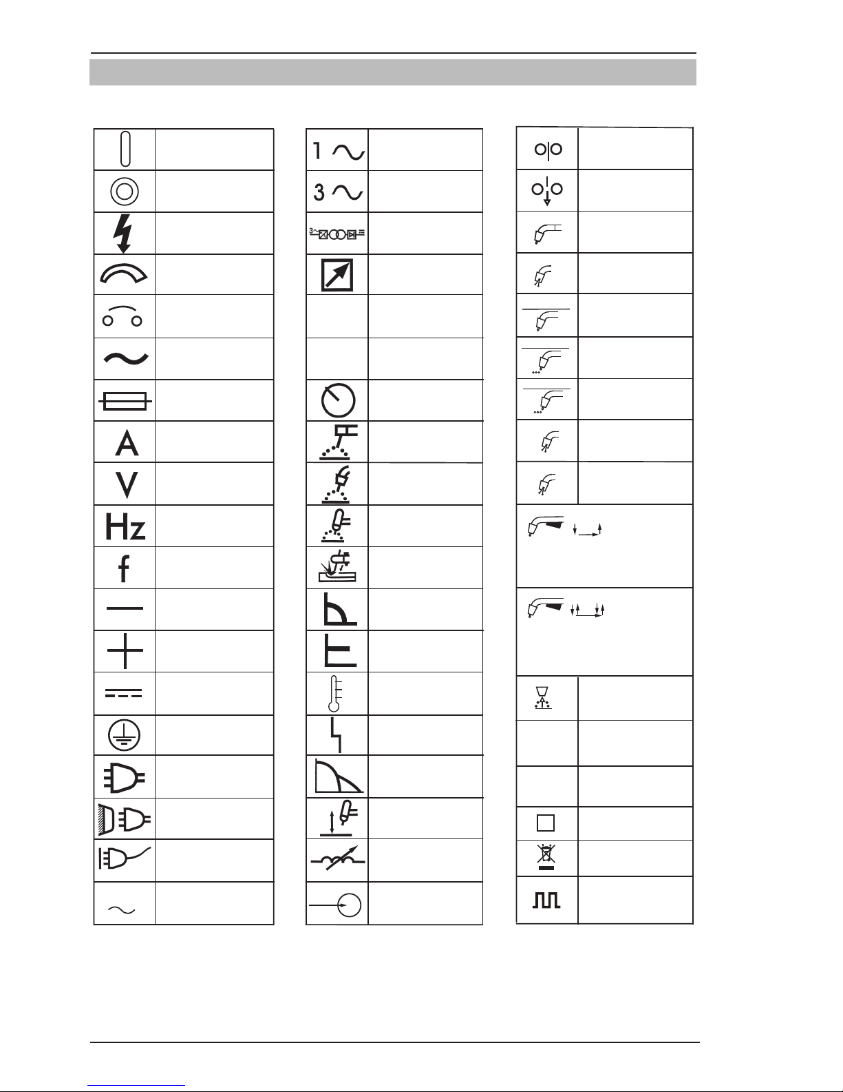
1.03 Symbol Chart
Note that only some of these symbols will appear on your model.
Gas Tungsten Arc
Welding (GTAW)
Air Carbon Arc
Cutting (CAC-A)
Constant Current
Constant Voltage
Or Constant Potential
High Temperature
Fault Indication
Arc Force
Touch Start (GTAW)
Variable Inductance
Voltage Input
Single Phase
Three Phase
Three Phase Static
Frequency ConverterTransformer-Rectifier
Dangerous Voltage
OFF
ON
Panel/Local
Shielded Metal
Arc Welding (SMAW)
Gas Metal Arc
Welding (GMAW)
Increase/Decrease
Circuit Breaker
AC Auxiliary Power
Remote
Duty Cycle
Percentage
Amperage
Voltage
Hertz (cycles/sec)
Frequency
Negative
Positive
Direct Current (DC)
Protective Earth
(Ground)
Line
Line Connection
Auxiliary Power
Receptacle RatingAuxiliary Power
Art # A-10663_AB
115V 15A
t
t1
t2
%
X
IPM
MPM
t
V
Fuse
Wire Feed Function
Wire Feed Towards
Workpiece With
Output Voltage OFF.
Preflow Time
Postflow Time
Spot Time
Spot Weld Mode
Continuous Weld
Mode
Press to initiate wirefeed and
welding, release to stop.
Purging Of Gas
Inches Per Minute
Meters Per Minute
Welding Gun
Burnback Time
Press and hold for preflow, release
to start arc. Press to stop arc, and
hold for preflow.
4 Step Trigger
Operation
2 Step Trigger
Operation
S
See Note
See Note
Pulse Welding
Page 13
SAFETY INSTRUCTIONS 202 AC/DC
Manual 0-5239 1-7 SAFETY INSTRUCTIONS AND WARNINGS
1.04 Declaration Of Conformity
Manufacturer: Victor Technologies Inc
Address: 16052 Swingley Ridge Road, Suite 300
St Louis, MO 63017
USA
The equipment described in this manual conforms to all applicable aspects and regulations of the ‘Low Voltage
Directive’ (European Council Directive 2006/95/EC) and to the National legislation for the enforcement of this
Directive.
The equipment described in this manual conforms to all applicable aspects and regulations of the “EMC
Directive” (European Council Directive 2004/108/EC) and to the National legislation for the enforcement of
this Directive.
Serial numbers are unique with each individual piece of equipment and details description, parts used to
manufacture a unit and date of manufacture.
National Standard and Technical Specifications
The product is designed and manufactured to a number of standards and technical requirements. Among
them are:
• CENELECEN50199EMCProductStandardforArcWeldingEquipment.
• ISO/IEC60974-1(BS638-PT10)(EN60974-1)(EN50192)(EN50078)applicabletoweldingequipment
and associated accessories.
• Forenvironmentswithincreasedhazardofelectricalshock,PowerSuppliesbearingtheSmark
conform to EN50192 when used in conjunction with hand torches with exposed cutting tips, if
equipped with properly installed standoff guides.
• Extensiveproductdesignverificationisconductedatthemanufacturingfacilityaspartoftheroutine
design and manufacturing process. This is to ensure the product is safe, when used according to
instructions in this manual and related industry standards, and performs as specified. Rigorous testing
is incorporated into the manufacturing process to ensure the manufactured product meets or exceeds
all design specifications.
• 2002/95/ECRoHSdirective.
!
WARNING
This equipment does not comply with IEC 61000-3-12. If it is connected to a public low voltage
system, it is the responsibility of the installer or user of the equipment to ensure, by consultation
with the distribution network operator if necessary, that the equipment may be connected.
Victor Technologies has been manufacturing products for more than 30 years, and will continue to achieve
excellence in our area of manufacture.
Manufacturers responsible representative:
Steve Ward
Operations Director
Victor Technologies Inc
Europa Building
Chorley N Industrial Park
Chorley, Lancashire,
England PR6 7BX
Page 14

202 AC/DC SAFETY INSTRUCTIONS
SAFETY INSTRUCTIONS AND WARNINGS 1-8 Manual 0-5239
This Page Intentionally Blank
Page 15
INTRODUCTION 202 AC/DC INVERTER
Manual 0-5239 2-1 INTRODUCTION
SECTION 2:
INTRODUCTION
2.02 Equipment Identification
The unit’s identification number (specification or
part number), model, and serial number usually appear on a nameplate attached to the control panel. In
some cases, the nameplate may be attached to the
rear panel. Equipment which does not have a control
panel such as gun and cable assemblies is identified
only by the specification or part number printed on
the shipping container. Record these numbers on the
bottom of page ii for future reference.
2.03 Receipt of Equipment
When you receive the equipment, check it against the
invoice to make sure it is complete and inspect the
equipment for possible damage due to shipping. If
there is any damage, notify the carrier immediately to
file a claim. Furnish complete information concerning
damage claims or shipping errors to the location in
your area listed in the inside back cover of this manual.
Include all equipment identification numbers as
described above along with a full description of the
parts in error.
Move the equipment to the installation site before
un-crating the unit. Use care to avoid damaging the
equipment when using bars, hammers, etc., to uncrate the unit.
2.01 How To Use This Manual
To ensure safe operation, read the entire manual,
including the chapter on safety instructions and
warnings.
Throughout this manual, the words WARNING,
CAUTION, and NOTE may appear. Pay particular attention to the information provided under these headings. These special annotations are easily recognized
as follows:
!
WARNING
A WARNING gives information regarding
possible personal injury.
CAUTION
A CAUTION refers to possible equipment
damage.
NOTE
A NOTE offers helpful information con
-
cerning certain operating procedures.
You will also notice icons from the safety section appearing throughout the manual. These are to advise
you of specific types of hazards or cautions related
to the portion of information that follows. Some may
have multiple hazards that apply and would look
something like this:
Page 16
INTRODUCTION 202 AC/DC INVERTER
INTRODUCTION 2-2 Manual 0-5239
2.04 Description
The Thermal Arc 202 AC/DC is a single phase constant
current welding inverter capable of performing MMA
(Stick), GTAW (HF TIG) and GTAW (Lift TIG) welding
processes. The unit is equipped with digital amperage and voltage meters, and a host of other features
in order to fully satisfy the broad operating needs of
the modern user. The unit is also fully compliant to
European Standard EN 60974-1 and IEC 60974.1.
The 202 AC/DC provides excellent welding performance across a broad range of applications when
used with the correct welding consumables and
procedures. The following instructions detail how
to correctly and safely set up the machine and give
guidelines on gaining the best efficiency and quality
from the Power Source. Please read these instructions
thoroughly before using the unit.
2.05 User Responsibility
This equipment will perform as per the information
contained herein when installed, operated, maintained
and repaired in accordance with the instructions provided. This equipment must be checked periodically.
Defective equipment (including welding leads) should
not be used. Parts that are broken, missing, plainly
worn, distorted or contaminated, should be replaced
immediately. Should such repairs or replacements
become necessary, it is recommended that such repairs be carried out by appropriately qualified persons
approved by Thermal Arc. Advice in this regard can
be obtained by contacting an Accredited Thermal Arc
Distributor.
This equipment or any of its parts should not be altered from standard specification without prior written
approval of Thermal Arc. The user of this equipment
shall have the sole responsibility for any malfunction
which results from improper use or unauthorized
modification from standard specification, faulty
maintenance, damage or improper repair by anyone
other than appropriately qualified persons approved
by Thermal Arc.
2.06 Transporting Methods
This unit is equipped with a handle for carrying
purposes.
!
WARNING
ELECTRIC SHOCK can kill. DO NOT TOUCH
live electrical parts. Disconnect input
power conductors from de-energized
supply line before moving the welding
power source.
!
WARNING
FALLING EQUIPMENT can cause serious
personal injury and equipment damage.
Lift unit with handle on top of case.
Use handcart or similar device of adequate capacity.
If using a fork lift vehicle, place and secure unit on a
proper skid before transporting.
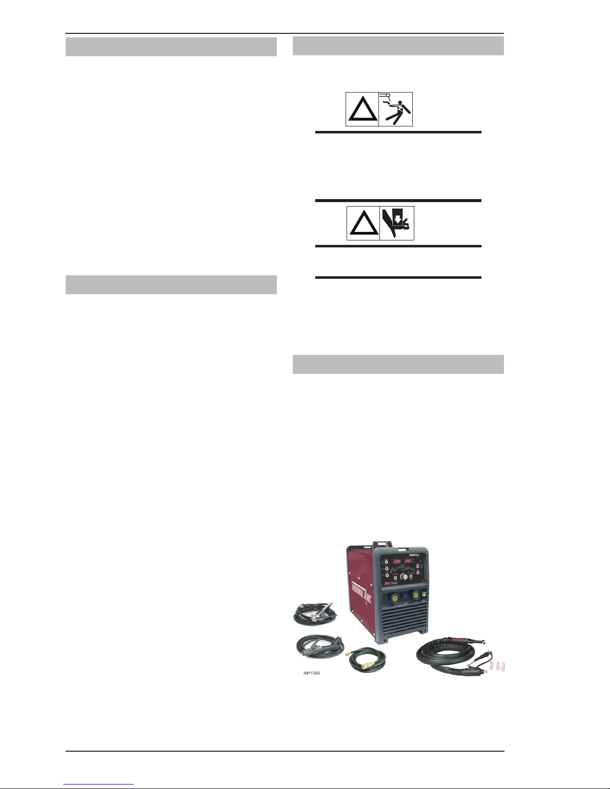
2.07 Packaged Items
• 202AC/DCInverterPowerSource
• Electrodeholderwith4mlead
• WorkClampwith4mlead
• TigTorch3.8m(12.5ft)leadwithremotecurrent
control
• TigTorchAccessorykit
• ShieldingGasHoseAssembly
• ElectrodeBonus
• ShoulderStrap
• OperatingManual
A#11392
Figure 2-1: 202 AC/DC System Packaged
Page 17

INTRODUCTION 202 AC/DC INVERTER
Manual 0-5239 2-3 INTRODUCTION
2.08 Specifications
Description Thermal Arc 202 AC/DC
Part Number W1006305
Power Source Mass 22 kg
Power Source Dimensions H 400mm x W 240mm x D 475mm
Cooling Fan Cooled
Welder Type Inverter Power Source
European Standards EN 60974-1 / IEC 60974-1
Number of Phases 1
Nominal Supply Voltage 230V +/- 15%
Nominal Supply Frequency 50/60Hz
Welding Current Range (DC STICK Mode) 10 – 170A
Welding Current Range (DC TIG Mode) 10 - 200A
Effective Input Current (I
1eff) (note1)
STICK
TIG
15.5A
14.1A
Maximum Input Current (I
1max)
STICK
TIG
34.9A
32.4A
Single Phase Generator Requirement (note2) 9.5kVA
STICK (MMA)
Welding Output, 40ºC, 10 min.
170A @ 15%, 26.8V
100A @ 60%, 24.0V
80A @ 100%, 23.2V
TIG (GTAW)
Welding Output, 40ºC, 10 min.
200A @ 20%, 18V
116A @ 60%, 14.6V
90A @ 100%, 13.6V
Open circuit voltage 70.3V DC / 50 VAC
Protection Class IP23S
Table 2-1: 202 AC/DC Specification
NOTE
Note 1: The Effective Input Current should be used for the determination of cable size & supply
requirements.
Note 2: Generator Requirements at the Maximum Output Duty Cycle.
Note 3: Motor start fuses or thermal circuit breakers are recommended for this application. Check
local requirements for your situation in this regard.
Due to variations that can occur in manufactured products, claimed performance, voltages, ratings,
all capacities, measurements, dimensions and weights quoted are approximate only. Achievable
capacities and ratings in use and operation will depend upon correct installation, use, applications,
maintenance and service.
Page 18
INTRODUCTION 202 AC/DC INVERTER
INTRODUCTION 2-4 Manual 0-5239
26 Style TIG Torch with Remote Current Control .. Part No. W4013601
Foot Control 7.6 m ................................ Part No. 10-4016
Tweco Helmet ..................................... Part No. WHF41001
2.09 Duty Cycle
The rated duty cycle of a Welding Power Source, is a statement of the time it may be operated at its rated
welding current output without exceeding the temperature limits of the insulation of the component parts. To
explain the 10 minute duty cycle period the following example is used. Suppose a Welding Power Source is
designed to operate at a 20% duty cycle, 200 amperes at 18.0 volts. This means that it has been designed
and built to provide the rated amperage (200A) for 2 minutes, i.e. arc welding time, out of every 10 minute
period (20% of 10 minutes is 2 minutes). During the other 8 minutes of the 10 minute period the Welding
Power Source must idle and be allowed to cool. The thermal cut out will operate if the duty cycle is exceeded.
10 20 30 40 50 60 70 80 90 100 110 120 130 140 150 160 170 180 190 200 210 220
Welding Current (AMPS)
SAFE OPERATING REGION
(TIG & STICK)
0
0
10
20
30
40
60
70
50
80
100
90
Duty Cycle (PERCENTAGE)
GTAW (TIG)
MMA (STICK)
A-11402
202 AC/DC
Figure 2-2: 202 AC/DC Duty Cycle
2.10 Optional Accessories
Page 19
INSTALLATION/SETUP 202 AC/DC INVERTER
Manual 0-5239 3-1 INSTALLATION, OPERATION AND SETUP
SECTION 3:
INSTALLATION, OPERATION AND SETUP
G. The enclosure design of this power source
meets the requirements of IP23S as outlined in
EN 60529. This provides adequate protection
against solid objects (greater than 12mm), and
direct protection from vertical drops. Under no
circumstances should the unit be operated or
connected in a micro environment that will exceed
the stated conditions. For further information
please refer to EN 60529.
H. Precautions must be taken against the power
source toppling over. The power source must
be located on a suitable horizontal surface in the
upright position when in use.
WARNING
This equipment should be electrically
connected by a qualified electrician.
3.03 Ventilation
!
WARNING
Since the inhalation of welding fumes can
be harmful, ensure that the welding area
is effectively ventilated.
3.04 Mains Supply Voltage
Requirements
The Mains supply voltage
should be within ± 15% of the rated mains supply
voltage. Too low a voltage may cause poor welding
performance. Too high a supply voltage will cause
components to overheat and possibly fail.
The Welding Power Source must be:
• Correctlyinstalled,ifnecessary,byaqualied
electrician.
• Correctlyearthed (electrically) in accordance
with local regulations.
• Connectedtothecorrectsizepowerpointand
fuse as per the Specifications on page 2-5.
3.01 Environment
This machine is not designed for use in environments
with increased hazard of electric shock as outlined
in EN 60974.1. Additional safety precautions may
be required when using unit in an environment with
increased hazard of electric shock. Please refer to
relevant local standards for further information prior
to using in such areas.
A. Examples of environments with increased hazard
of electric shock are:
1. In locations in which freedom of movement
is restricted, so that the operator is forced
to perform the work in a cramped (kneeling,
sitting or lying) position with physical contact
with conductive parts.
2. In locations which are fully or partially limited
by conductive elements, and in which there
is a high risk of unavoidable or accidental
contact by the operator.
3. In wet or damp hot locations where humidity
or perspiration considerable reduces the
skin resistance of the human body and the
insulation properties of accessories.
B. Environments with increased hazard of electric
shock do not include places where electrically
conductive parts in the near vicinity of the
operator, which can cause increased hazard, have
been insulated.
3.02 Location
Be sure to locate the welder according to the following
guidelines:
A. In areas, free from moisture and dust.
B. Ambient temperature between 0° C to 40° C.
C. In areas, free from oil, steam and corrosive
gases.
D. In areas, not subjected to abnormal vibration or
shock.
E. In areas, not exposed to direct sunlight or rain.
F. Place at a distance of 300mm or more from walls
or similar that could restrict natural air flow for
cooling.
Page 20
INSTALLATION/SETUP 202 AC/DC INVERTER
INSTALLATION, OPERATION AND SETUP 3-2 Manual 0-5239
!
WARNING
Any electrical work must be carried out by
a qualified Electrical Tradesperson.
3.05 High Frequency Introduction
The importance of correct installation of high frequency
welding equipment cannot be overemphasized.
Interference due to high frequency initiated or
stabilized arc is almost invariably traced to improper
installation. The following information is intended
as a guide for personnel installing high frequency
welding machines.
!
WARNING EXPLOSIVES
The high frequency section of this machine
has an output similar to a radio transmitter.
The machine should NOT be used in the
vicinity of blasting operations due to the
danger of premature firing
!
WARNING COMPUTER
It is also possible that operation close
to computer installations may cause
computer malfunction.
3.06 High Frequency Interference
Interference may be transmitted by a high frequency
initiated or stabilized arc welding machine in the
following ways.
1. Direct Radiation: Radiation from the machine can
occur if the case is metal and is not properly grounded.
It can occur through apertures such as open access
panels. The shielding of the high frequency unit in
the Power Source will prevent direct radiation if the
equipment is properly grounded.
2. Transmission via the Supply Lead: Without
adequate shielding and filtering, high frequency energy
may be fed to the wiring within the installation (mains)
by direct coupling. The energy is then transmitted by
both radiation and conduction. Adequate shielding
and filtering is provided in the Power Source.
3. Radiation from Welding Leads: Radiated
interference from welding leads, although pronounced
in the vicinity of the leads, diminishes rapidly with
distance. Keeping leads as short as possible will
minimise this type of interference. Looping and
suspending of leads should be avoided wherever
possible.
4. Re-Radiation from Unearthed Metallic Objects:
A major factor contributing to interference is reradiation from unearthed metallic objects close to the
welding leads. Effective grounding of such objects will
prevent re-radiation in most cases.
3.07 Electromagnetic Compatibility
!
WARNING
Extra precautions for Electromagnetic
Compatibility may be required when
this Welding Power Source is used in a
domestic situation.
A. Installation and Use - Users Responsibility
The user is responsible for installing and
using the welding equipment according to the
manufacturer’s instructions. If electromagnetic
disturbances are detected then it shall be the
responsibility of the user of the welding equipment
to resolve the situation with the technical
assistance of the manufacturer. In some cases this
remedial action may be as simple as earthing the
welding circuit, see NOTE below. In other cases
it could involve constructing an electromagnetic
screen enclosing the Welding Power Source and
the work, complete with associated input filters.
In all cases, electromagnetic disturbances shall
be reduced to the point where they are no longer
troublesome.
NOTE
The welding circuit may or may not be
earthed for safety reasons. Changing the
earthing arrangements should only be
authorised by a person who is competent
to assess whether the changes will
increase the risk of injury, e.g. by allowing
parallel welding current return paths which
may damage the earth circuits of other
equipment. Further guidance is given in
IEC 60974-13 Arc Welding Equipment Installation and use (under preparation).
B. Assessment of Area
Before installing welding equipment, the user shall
make an assessment of potential electromagnetic
problems in the surrounding area. The following
shall be taken into account
1. Other supply cables, control cables, signalling
and telephone cables; above, below and
adjacent to the welding equipment.
2. Radio and television transmitters and
receivers.
Page 21

INSTALLATION/SETUP 202 AC/DC INVERTER
Manual 0-5239 3-3 INSTALLATION, OPERATION AND SETUP
3. Computer and other control equipment.
4. Safety critical equipment, e.g. guarding of industrial equipment.
5. The health of people around, e.g. the use of pacemakers and hearing aids.
6. Equipment used for calibration and measurement.
7. The time of day that welding or other activities are to be carried out.
8. The immunity of other equipment in the environment: the user shall ensure that other equipment being
used in the environment is compatible: this may require additional protection measures.
The size of the surrounding area to be considered will depend on the structure of the building and other
activities that are taking place. The surrounding area may extend beyond the boundaries of the premises.
C. Methods of Reducing Electromagnetic Emissions
1. Mains Supply
Welding equipment should be connected to the mains supply according to the manufacturer’s
recommendations. If interference occurs, it may be necessary to take additional precautions such as
filtering of the mains supply. Consideration should be given to shielding the supply cable of permanently
installed welding equipment in metallic conduit or equivalent. Shielding should be electrically continuous
throughout its length. The shielding should be connected to the Welding Power Source so that good
electrical contact is maintained between the conduit and the Welding Power Source enclosure.
2. Maintenance of Welding Equipment
The welding equipment should be routinely maintained according to the manufacturer’s recommendations.
All access and service doors and covers should be closed and properly fastened when the welding
equipment is in operation. The welding equipment should not be modified in any way except for those
changes and adjustments covered in the manufacturer’s instructions. In particular, the spark gaps of
arc striking and stabilising devices should be adjusted and maintained according to the manufacturer’s
recommendations.
3. Welding Cables
The welding cables should be kept as short as possible and should be positioned close together, running
at or close to the floor level.
4. Equipotential Bonding
Bonding of all metallic components in the welding installation and adjacent to it should be considered.
However. Metallic components bonded to the work piece will increase the risk that the operator could
receive a shock by touching the metallic components and the electrode at the same time. The operator
should be insulated from all such bonded metallic components.
5. Earthing of the Workpiece
Where the workpiece is not bonded to earth for electrical safety, nor connected to earth because of it’s
size and position, e.g. ship’s hull or building steelwork, a connection bonding the workpiece to earth
may reduce emissions in some, but not all instances. Care should be taken to prevent the earthing of
the workpiece increasing the risk of injury to users, or damage to other electrical equipment. Where
necessary, the connection of the workpiece to earth should be made by direct connection to the
workpiece, but in some countries where direct connection is not permitted, the bonding should be
achieved by suitable capacitance, selected according to national regulations.
6. Screening and Shielding
Selective screening and shielding of other cables and equipment in the surrounding area may alleviate
problems of interference. Screening the entire welding installation may be considered for special
applications.
Page 22
INSTALLATION/SETUP 202 AC/DC INVERTER
INSTALLATION, OPERATION AND SETUP 3-4 Manual 0-5239
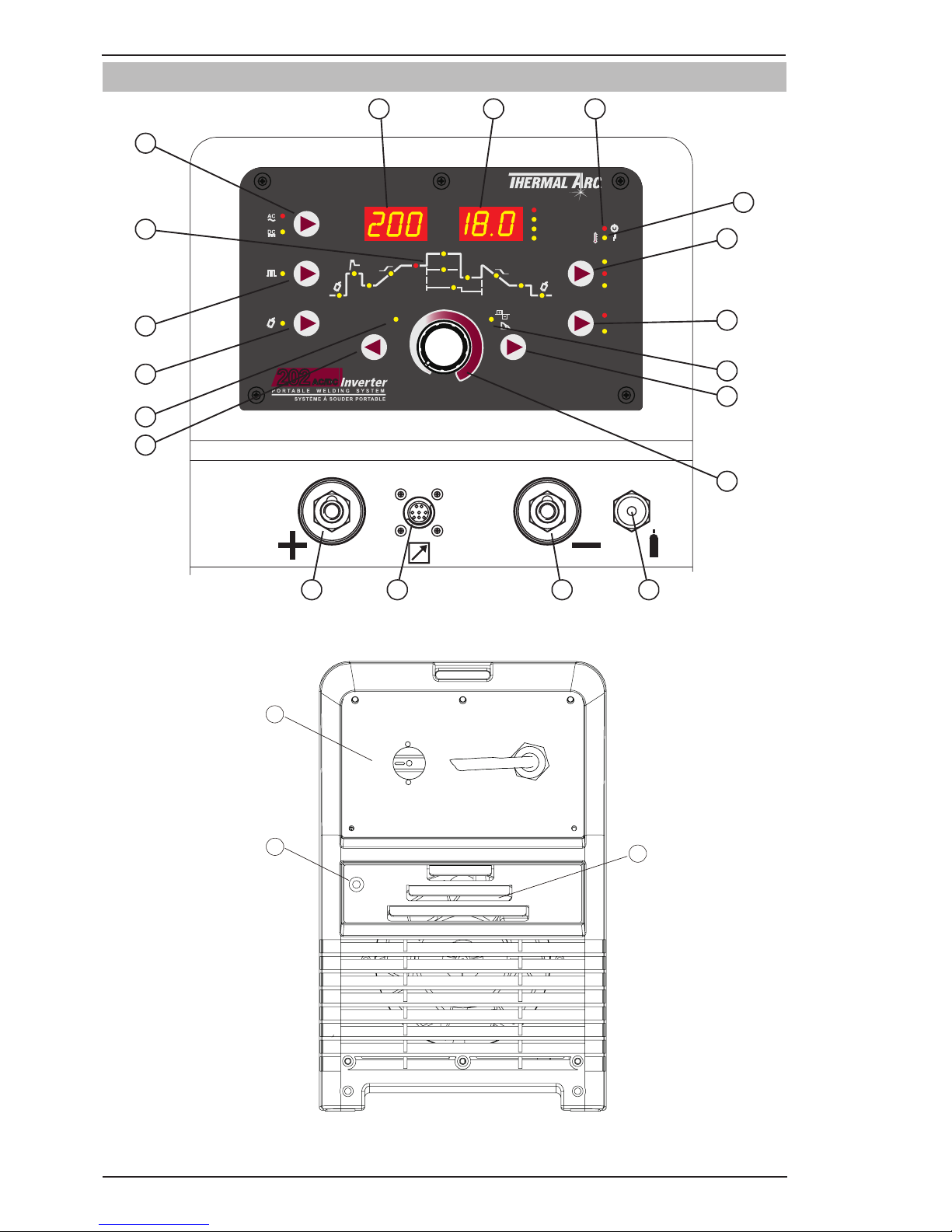
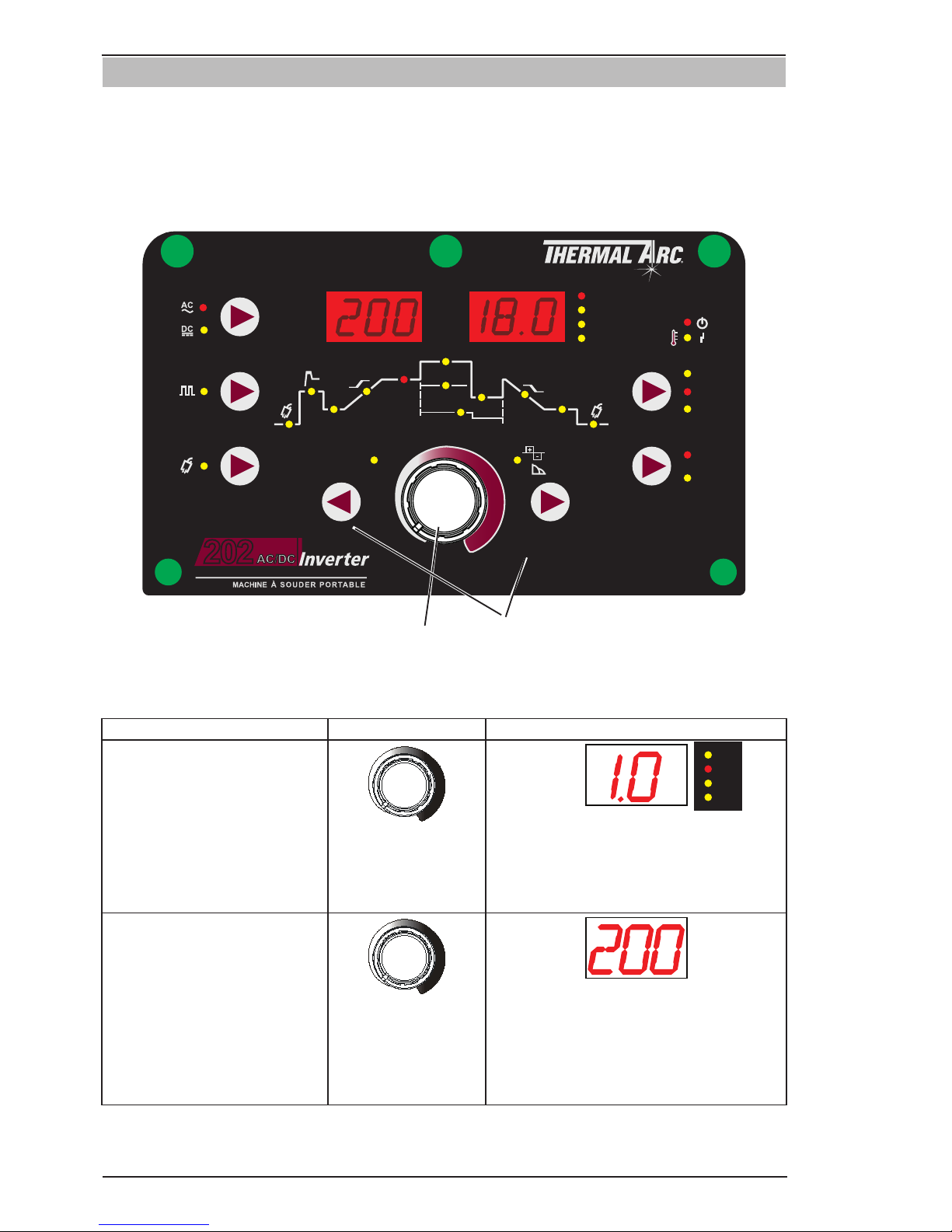
3.08 202 AC/DC Power Source Controls, Indicators and Features
FAULT
POWER
Amps
Volts
FORWARDBACK
VOLTS
SECONDS
PERCENT (%)
FREQ (Hz)
AC FREQUENCY
WAVE BALANCE
(ARC FORCE)
MODE
AC
DC
PULSE
PURGE
PROCESS
TRIGGER
2T NORMAL
4T LATCH
HF TIG
LIFT TIG
STICK
Pre
Flow
Hot
Start
Initial
Current
Up
Slope
Base
Current
Peak
Current
Width
Trough
Current
Frequency
Down
Slope
Crater
Current
Post
Flow
WeldSkill
PORTABLE WELDING MACHINE
200
AC/DC
Inverter
8
1 2 3 4
A-11403
I
z
I
s
I
2
I
e
I
1
MODE
PULSE
PURGE
PROCESS
LIFT TIG
V
SEC
%
Hz
HF TIG
STICK
2T
4T
TRIGGER
BACK FORWARD
AC FREQUENCY
WAVE BALANCE
ARC FORCE
Pre
Flow
Post
Flow
Initial
Current
Up
Slope
Down
Slope
Crater
Current
Base
Current
Frequency
f
w
Width
High Current
Low
Current
Hot
Start
t1
t2
AV
5
6
7
8
9
10
11
12
13
14
15
16
17
18 19
202
Figure 3-1: Controls on Front Panel
21
20
A-11232
ON
OFF
22
Figure 3-2: Rear Panel
Page 23
INSTALLATION/SETUP 202 AC/DC INVERTER
Manual 0-5239 3-5 INSTALLATION, OPERATION AND SETUP
1. Positive Welding Terminal
Positive Welding Terminal. Welding current flows from the Power Source via heavy duty bayonet type
terminals. It is essential, however, that the male plug is inserted and turned securely to achieve a sound
electrical connection.
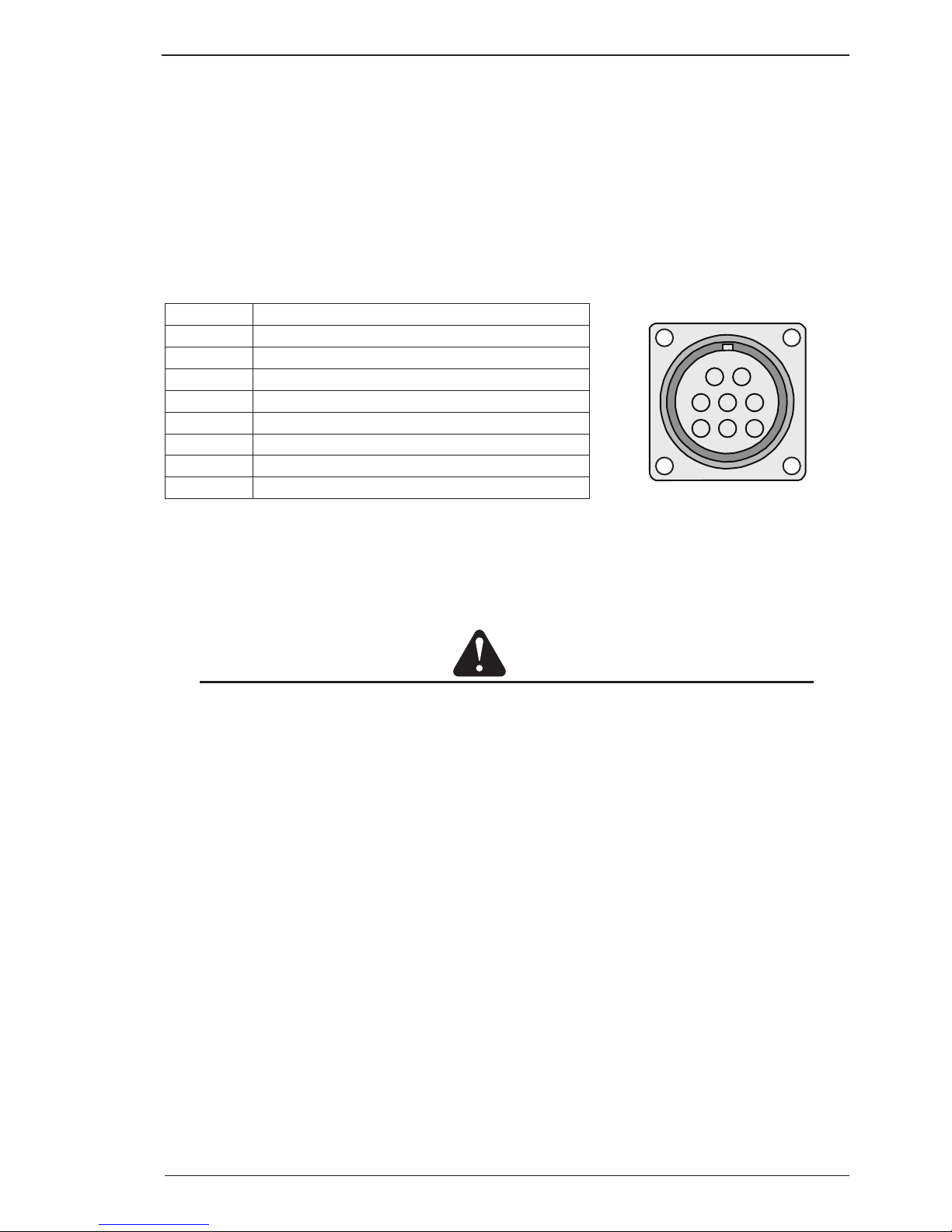
2. 8 Pin Control Socket
The 8 pin receptacle is used to connect a trigger switch or remote control to the welding Power Source
circuitry:
To make connections, align keyway, insert plug, and rotate threaded collar fully clockwise. The socket
information is included in the event the supplied cable is not suitable and it is necessary to wire a plug or
cable to interface with the 8 pin receptacle.
Socket Pin Part Number / Description
1 Not used
2 Trigger Switch Input
3 Trigger Switch Input
4 Not used
5 Remote Control 5k ohm Potentiometers Maximum
6 Remote Control 5k ohm Potentiometers Minimum
7 Remote Control 5k ohm Potentiometer Wiper
8 Not used
Table 3-1: 8 Pin Interconnection Control Plug Configuration
3. Negative Welding Terminal
Negative Welding Terminal. Welding current flows from the Power Source via heavy duty bayonet type
terminals. It is essential, however, that the male plug is inserted and turned securely to achieve a sound
electrical connection
CAUTION
Loose welding terminal connections can cause overheating and result in the male plug being fused in the
terminal.
4. Shielding Gas Outlet
The Shielding Gas Outlet located on the front panel is a 5/8-18 UNF female gas fitting and is utilised for
the connection of a suitable TIG Torch.
5. Power ON Indicator
The POWER ON indicator illuminates when the ON/OFF switch (20) is in the ON position and the correct
mains voltage is present.
6. Thermal Overload Indicator Light
This welding power source is protected by a self resetting thermostat. The indicator will illuminate if the
duty cycle of the power source has been exceeded. Should the thermal overload indicator illuminate the
output of the power source will be disabled. Once the power source cools down this light will go OFF and
the over temperature condition will automatically reset. Note that the mains power switch should remain
in the on position such that the fan continues to operate thus allowing the unit to cool sufficiently. Do not
switch the unit off should a thermal overload condition be present.
3
4
5
6
7
8
1
2
A-11228
Page 24
INSTALLATION/SETUP 202 AC/DC INVERTER
INSTALLATION, OPERATION AND SETUP 3-6 Manual 0-5239
7. Process Selection Button
The process selection control is used to select the desired welding mode. Three modes are available,
GTAW (LIFT TIG), GTAW (HF TIG) and MMA (Stick) modes.
Note that when the unit is powered off the mode selection control will automatically default to LIFT TIG
for Stick or LIFT TIG modes and HF TIG for HF TIG mode.
This is necessary so as to prevent inadvertent arcing should an electrode holder be connected to the unit
and mistakenly be in contact with the work piece during power up.
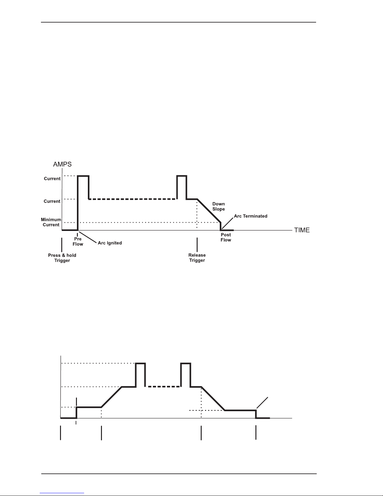
8. Trigger Mode Control Button (HF TIG and LIFT TIG Mode only)
The trigger mode control is used to switch the functionality of the torch trigger between 2T (normal), and
4T (latch mode).
2T Normal Mode
In this mode, the torch trigger must remain depressed for the welding output to be active. Press and hold
the torch trigger to activate the power source (weld). Release the torch trigger switch to cease welding.
A-11409
High
Low
Figure 3-3
4T Latch Mode
This mode of welding is mainly used for long welding runs to reduce operator fatigue. In this mode the
operator can press and release the torch trigger and the output will remain active. To deactivate the power
source, the trigger switch must again be depressed and realised, thus eliminating the need for the operator
to hold the torch trigger.
Note that when operating in GTAW (HF and LIFT TIG modes), the power source will remain activated until
the selected down slope time has elapsed
Press & hold
Trigger
Base
Current
High
Current
Down
Slope
Post
Flow
AMPS
TIME
Pre
Flow
Up
Slope
Release
Trigger
Initial
Current
Arc Ignited
Arc Terminated
Press & hold
Trigger
Release
Trigger
Crater
Current
A-11410
Figure 3-4
Page 25

INSTALLATION/SETUP 202 AC/DC INVERTER
Manual 0-5239 3-7 INSTALLATION, OPERATION AND SETUP
9. Wave Balance / Arc Force Indicator
This indicator light will illuminate when programming Wave Balance (AC HF TIG mode only) or Arc Force
(STICK mode only).
10. Forward Programming Button
Pressing this button will advance to the next step in the programming sequence.
11. Multifunction Control
The multifunction control knob is used to adjust welding current.
It is also used to adjust parameters when in programming mode.
12. Back Programming Button
Pressing this button will go back to the previous step in the programming sequence.
13. AC frequency Indicator
This indicator light will illuminate when programming AC Frequency (AC HF TIG mode only).
14. Purge Button
Press and hold the PURGE button to purge the gas line in LIFT TIG and HF TIG modes. To PURGE the
shielding gas line in LIFT TIG and HF TIG modes press the PURGE button and release. The indicator will
illuminate and shielding gas will purge for a preset period of 15 seconds. (This cannot be adjusted). To stop
shielding gas from purging within this time press the PURGE button and release and the purge indicator
will extinguish and shielding gas will cease.
15 Pulse Button
Press the PULSE button to toggle Pulse On and OFF in LIFT TIG and HF TIG modes
16. Programming Parameter Indicators
These indicator lights will illuminate when programming.
17. Mode Button
Press the MODE button to toggle AC and DC output in LIFT TIG, HF TIG and STICK.
18. Digital Ammeter
The digital amperage meter is used to display both the pre-set current and actual output current of the
power source.
At times of non-welding, the amperage meter will display a pre-set (preview) amperage value. This value
can be adjusted by varying the multifunction control when the Programming Parameter Indicator light
shows BASE CURRENT.
When welding, the amperage meter will display actual welding current.
Should a remote device be connected the maximum setting of the power source will be determined by the
respective front panel control, irrespective of the remote control device setting. As an example, if the output
current on the power source front panel is set to 50% and the remote control device is set to 100%, the
maximum achievable output from the unit will be 50%. Should 100% output be required, the respective
power source front panel control must be set to 100%, in which case the remote device will then be able
to control between 0-100% output.
19. Digital Voltmeter / Parameter meter
The digital volt meter is used to display the actual output voltage of the power source. It is also used to
display Parameters in Programming Mode.
Page 26
INSTALLATION/SETUP 202 AC/DC INVERTER
INSTALLATION, OPERATION AND SETUP 3-8 Manual 0-5239
Depending on the Programming Parameter selected, the status indictor adjacent to the volt meter will
illuminate to show the units of the programming parameter.
When welding, the volt meter will display actual welding voltage.
20. On / Off Switch
This Switch is located on the rear of the Power Source and turns mains power off and on.
!
WARNING
When the front digital displays are lit, the machine is connected to the Mains supply voltage and
the internal electrical components are at Mains voltage potential
21. Shielding Gas Inlet
The Shielding Gas Inlet is a quick disconnect nipple suitable for connection of a gas hose to a regulated
Shielding Gas Supply. The Shielding Gas inlet is located on the rear of the Power Source.
22. Cooling Fan
The 202 AC/DC is fitted with a cooling fan that will operate continuously when the On/Off switch on the
rear panel is switched to the On position.
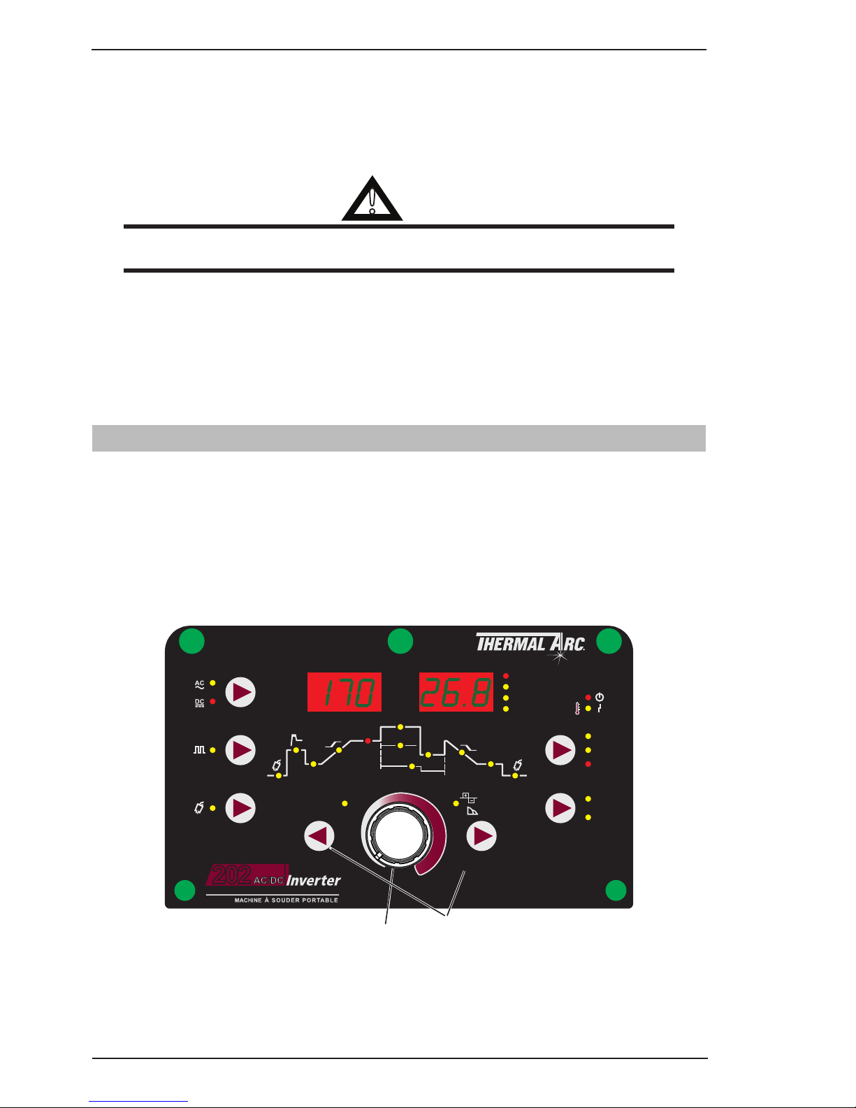
3.09 202 AC/DC - STICK Programming Mode
Press the PROCESS button to select STICK mode.
Press the MODE switch to toggle between AC and DC welding output. When AC is selected the frequency is
fixed at 50Hz.
The Programming LED’s are always active. Press FORWARD or BACK to cycle through available programming
functions.
Use the Multi Function Control to adjust the Parameter selected.
While welding the Multi Function Control directly controls the BASE CURRENT
I
z
I
s
I
2
I
e
I
1
MODE
PULSE
PURGE
PROCESS
LIFT TIG
V
SEC
%
Hz
HF TIG
STICK
2T
4T
TRIGGER
BACK FORWARD
AC FREQUENCY
PORTABLE WELDINGSY STEM
WAVE BALANCE
ARC FORCE
Pre
Flow
Post
Flow
Initial
Current
Up
Slope
Down
Slope
Crater
Current
Base
Current
Frequency
f
w
Width
High Current
Low
Current
Hot
Start
t1
t2
202
AV
Press to go forward / go back
between programming status
LED’s
Adjust programming parameter
A-11404
Figure 3-5: Stick Programming Mode
Page 27
INSTALLATION/SETUP 202 AC/DC INVERTER
Manual 0-5239 3-9 INSTALLATION, OPERATION AND SETUP
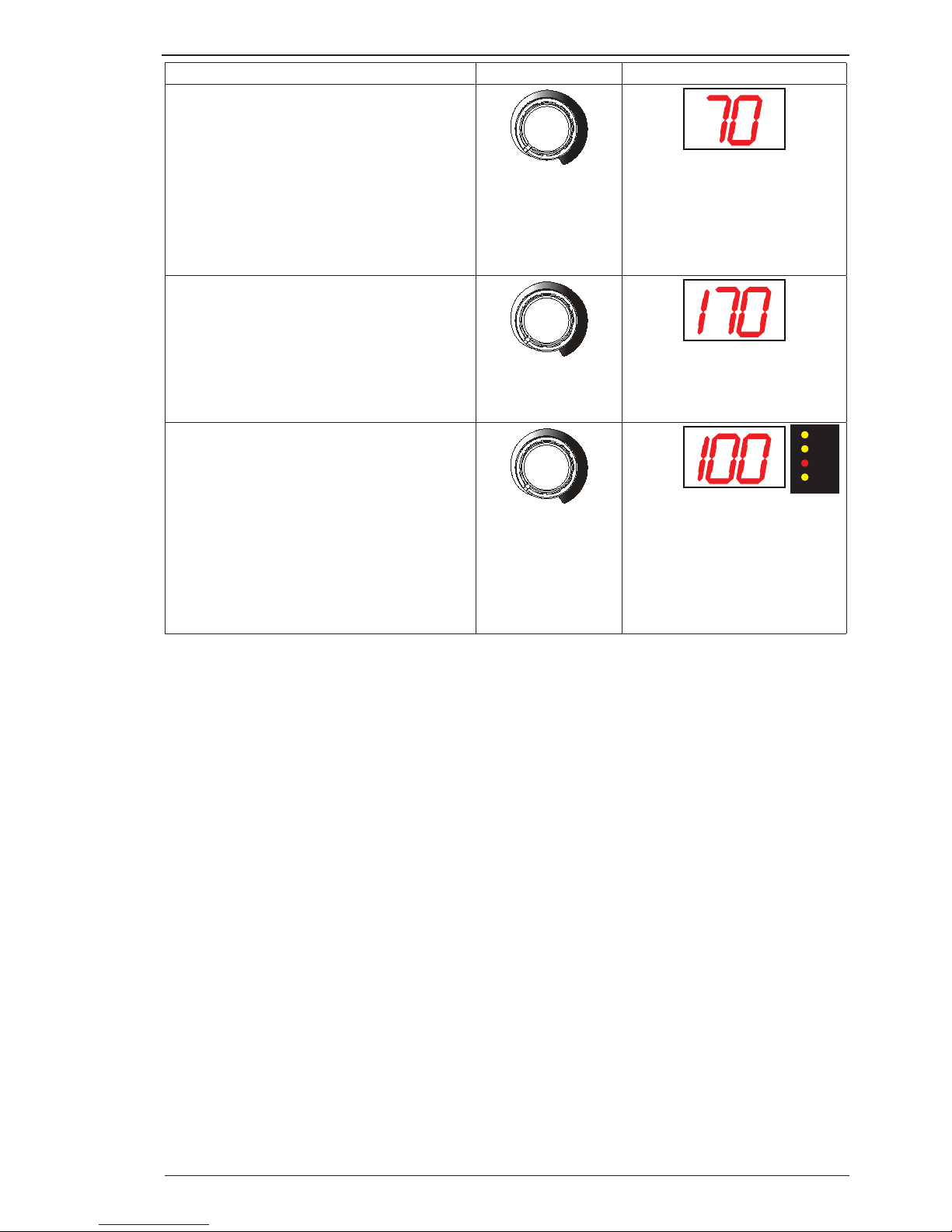
Programming Parameter Adjustment Device Display
Hot Start
This parameter operates in all weld modes
except LIFT TIG mode and is used to heat up
the weld zone in TIG modes or improve the
start characteristics for stick electrodes the
peak start current on top of the BASE (WELD)
current.
e.g. HOT START current = 130 amps when
BASE (WELD) = 100 amps & HOT START = 30
amps
Amps
0 to 70A (max 170A weld current)
Base Current
This parameter sets the TIG WELD current
when PULSE is OFF. This parameter also sets
the STICK weld current.
Amps
5 to 170A (DC STICK mode)
10 to 170A (AC STICK mode)
Arc Force (STICK Mode only)
Arc Force is effective when in Manual Arc
Mode only. Arc Force control provides and
adjustable amount of Arc Force (or "dig")
control. This feature can be particularly
beneficial in providing the operator the ability
to compensate for variability in joint fit-up in
certain situations with particular electrodes. In
general increasing the Arc Force control toward
100% (maximum Arc Force) allows greater
penetration control to be achieved.
Volts
0 to 100%
Table 3-2
V
SEC
%
Hz
Page 28
INSTALLATION/SETUP 202 AC/DC INVERTER
INSTALLATION, OPERATION AND SETUP 3-10 Manual 0-5239
3.10 202 AC/DC – LIFT TIG and HF TIG Programming Mode
Press the PROCESS button to select LIFT TIG or HF TIG mode.
Press the MODE switch to goggle between AC and DC welding output.
The Programming LED's are always active. Press FORWARD or BACK to cycle through available programming
functions.
Use the Multi Function Control Knob to adjust the parameter selected.
I
z
I
s
I
2
I
e
I
1
MODE
PULSE
PURGE
PROCESS
LIFT TIG
V
SEC
%
Hz
HF TIG
STICK
2T
4T
TRIGGER
BACK FORWARD
AC FREQUENCY
PORTABLE WELDINGSY STEM
WAVE BALANCE
ARC FORCE
Pre
Flow
Post
Flow
Initial
Current
Up
Slope
Down
Slope
Crater
Current
Base
Current
Frequency
f
w
Width
High Current
Low
Current
Hot
Start
t1
t2
202
AV
Press to go forward / go back
between programming status
LED’s
Adjust programming parameter
using the Multi Function Control knob
A-11405
Figure 3-6: LIFT TIG and HF TIG Programming Mode
Programming Parameter Adjustment Device Display
Pre-Flow
This parameter operates in
TIG modes only and is used to
provide gas to the weld zone
prior to striking the arc, once
the torch trigger switch has been
pressed. This control is used to
dramatically reduce weld porosity
at the start of a weld.
Volts
0.0 to 1.0 second
Initial Current
This parameter operates in (4T)
TIG modes only and is used to
set the start current for TIG. The
Start Current remains on until the
torch trigger switch is released
after it has been depressed.
Note: The maximum initial current
available will be limited to the set
value of the base current.
Amps
5 to 200 Amps (DC TIG mode)
30 to 200 Amps (AC LIFT TIG mode)
10 to 200A (AC HF TIG mode)
V
SEC
%
Hz
Page 29
INSTALLATION/SETUP 202 AC/DC INVERTER
Manual 0-5239 3-11 INSTALLATION, OPERATION AND SETUP
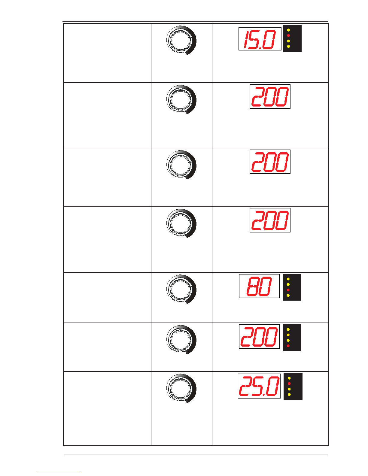
Up Slope
This parameter operates in (4T)
TIG modes only and is used to
set the time for the weld current
to ramp up, after the torch trigger
switch has been pressed then
released, from Initial Current to
High or BASE current.
V
SEC
%
Hz
Volts
0.0 to 15.0 seconds
Base Current
This parameter sets the TIG
WELD current when PULSE is
OFF. This parameter also sets the
STICK weld current.
Amps
5 to 200A (DC TIG mode)
30 to 200A (AC LIFT TIG mode)
10 to 200A (AC HF TIG mode)
High Current
This parameter sets the High weld
current when in PULSE mode.
Amps
10 to 200A (DC TIG mode)
30 to 200A (AC TIG mode)
Low Current
The lowest point in the pulse is
called the Low Current.
Amps
5 to 200A (DC HF TIG mode)
30 to 200A (AC LIFT TIG mode)
10 to 200A (AC HF TIG mode)
Pulse Width
This parameter sets the
percentage on time of the PULSE
FREQUENCY for High weld
current when the PULSE is ON.
V
SEC
%
Hz
Volts
15 to 80%
Pulse Frequency
This parameter sets the PULSE
FREQUENCY when the PULSE is
ON..
V
SEC
%
Hz
Volts
0.5 to 200 Hz
Down Slope
This parameter operates in TIG
modes only and is used to set
the time for the weld current
to ramp down, after the torch
trigger switch has been pressed,
to crater current. This control is
used to eliminate the crater that
can form at the completion of a
weld.
V
SEC
%
Hz
Volts
0.0 to 25.0 seconds
Page 30
INSTALLATION/SETUP 202 AC/DC INVERTER
INSTALLATION, OPERATION AND SETUP 3-12 Manual 0-5239
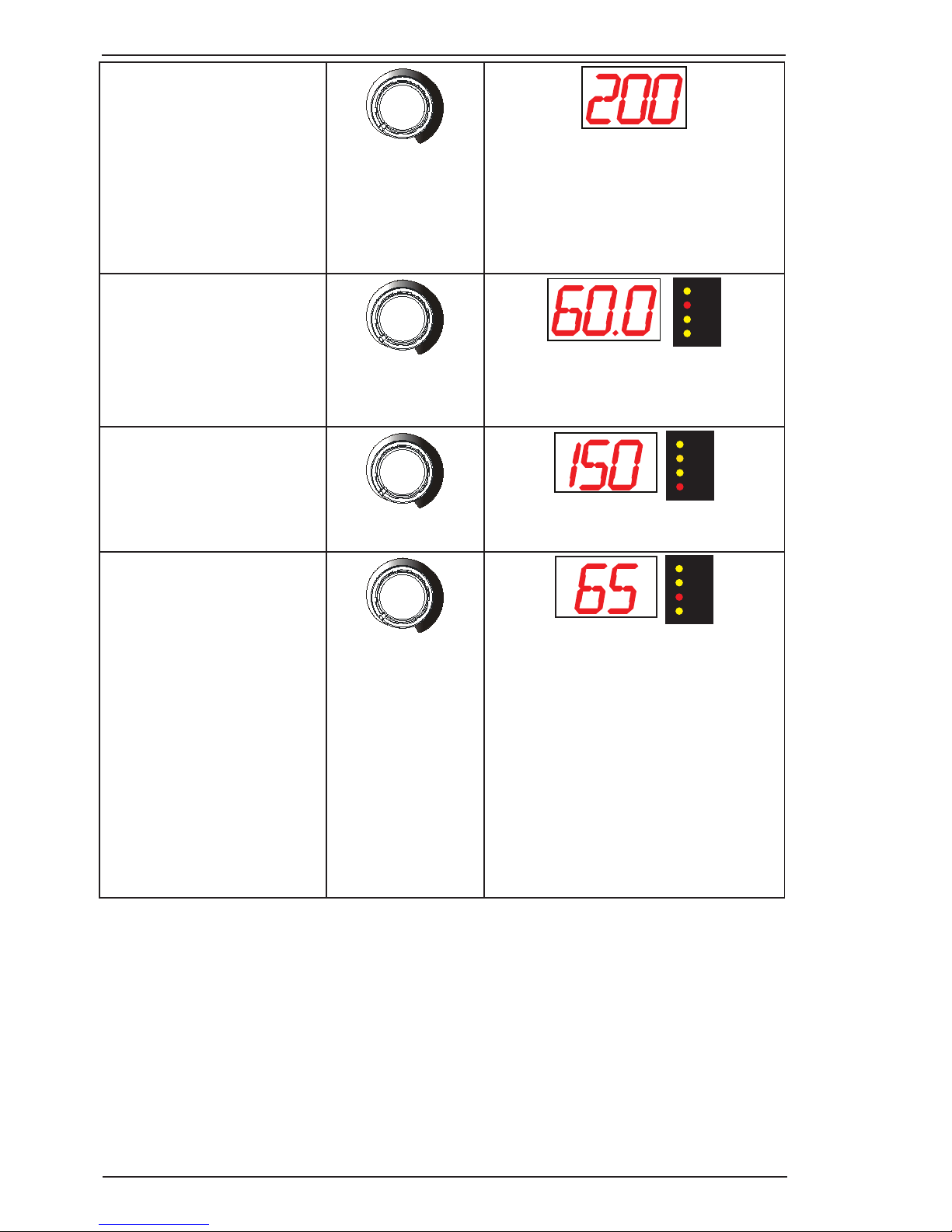
Crater Current
This parameter operates in (4T)
TIG modes only and is used to
set the finish current for TIG.
The CRATER Current remains
ON until the torch trigger switch
is released after it has been
depressed.
Note: The maximum crater
current available will be limited to
the set value of the base current.
Amps
5 to 200A (DC TIG mode)
30 to 200A (AC TIG mode)
10 to 200A (AC HF TIG mode)
Post Flow
This parameter operates in TIG
modes only and is used to adjust
the post gas flow time once
the arc has extinguished. This
control is used to dramatically
reduce oxidation of the tungsten
electrode.
V
SEC
%
Hz
Volts
0.0 to 60.0 seconds
AC Frequency
This parameter operates in AC
TIG mode only and is used to
set the frequency for the AC weld
current.
V
SEC
%
Hz
Volts
15 to 150 Hz
Wave Balance
This parameter operates in AC
TIG mode and is used to set the
penetration to cleaning action
ratio for the AC weld current.
Generally WAVE BALANCE is set
to 50% for AC STICK welding.
The WAVE BALANCE control
changes the ratio of penetration
to cleaning action of the AC TIG
welding arc. Maximum weld
penetration is achieved when
the WAVE BALANCE control is
set to 10%. Maximum cleaning
of heavily oxidised aluminium or
magnesium alloys is achieved
when the WAVE BALANCE control
is set to 65%.
V
SEC
%
Hz
Volts
10 to 65%
Table 3-3
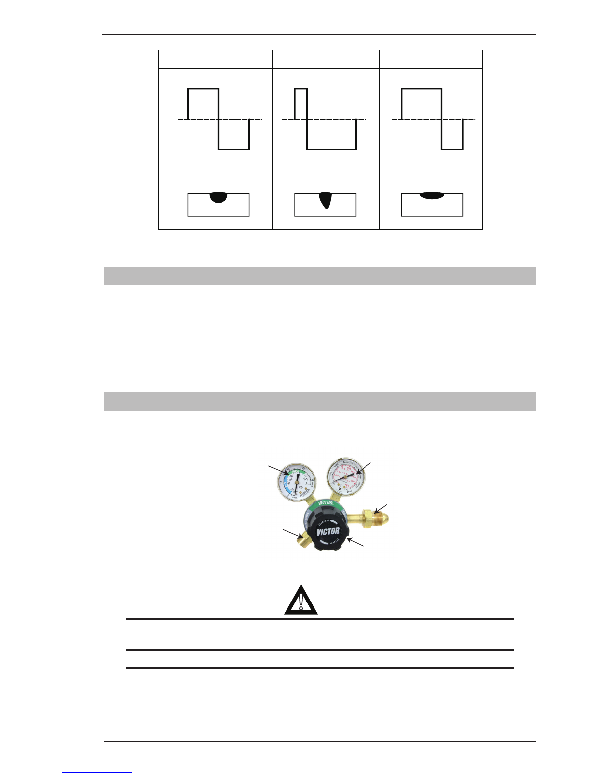
WAVE BALANCE is used for aluminium welding in AC HF TIG or AC LIFT TIG mode
It is used to set the ratio of penetration to cleaning action for the AC TIG welding arc.
Maximum weld penetration is achieved when the WAVE BALANCE is set to 10%. Maximum cleaning of heavily
oxidised aluminium or magnesium alloys is achieved when the WAVE BALANCE is set to 65%.
Page 31
INSTALLATION/SETUP 202 AC/DC INVERTER
Manual 0-5239 3-13 INSTALLATION, OPERATION AND SETUP
Maximum Penetration and
reduced cleaning
Balanced with 50% penetration
and 50% cleaning
Maximum Cleaning and
reduced penetration
10%50% 65%
90%50% 35%
(+)(+) (+)
(-)(-) (-)
Wave Balance = 50% Wave Balance = 10% Wave Balance = 65%
A-11223
Table 3-4: AC TIG Wave Balance
3.11 Short Circuit Protection While Welding
To prolong the useful life of a TIG tungsten electrode, the 202 AC/DC incorporates special circuitry.
In DC LIFT TIG mode, if the tungsten electrode touches the work the welding current is reduced to 40 Amps.
In DC HF TIG mode, if the tungsten electrode touches the work the welding current is reduced to 30 Amps
within 1 second.
In STICK mode, if the electrode touches the work for more than two seconds the welding current is reduced
to 0 Amps.
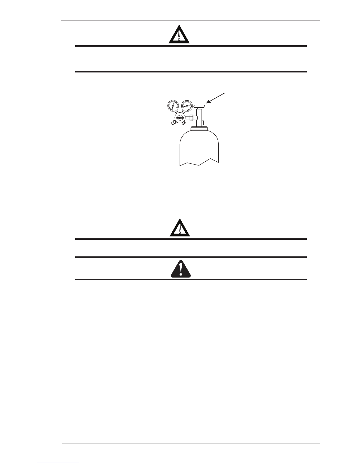
3.12 Victor Regulator
Pressure regulator (Figure 3-7) attached to the cylinder valve reduce high cylinder pressures to suitable low
working pressures for welding, cutting, and other applications.
LOW PRESSURE
GAUGE (DELIVERY)
HIGH PRESSURE
GAUGE (SUPPLY)
INLET
CONNECTION
OUTLET
CONNECTION
PRESSURE
ADJUSTING
SCREW
Art # A-09414
Figure 3-7: Victor CS Regulator
!
WARNING
Use the regulator for the gas and pressure for which it is designed. NEVER alter a regulator for
use with any other gas.
NOTE
Regulators purchased with open 1/8”, 1/4”, 3/8”, or 1/2” NPT ports must be assembled to their
intended system.
1. Note the maximum inlet pressure stamped on the regulator. DO NOT attach the regulator to a system
that has a higher pressure than the maximum rated pressure stamped on the regulator.
Page 32

INSTALLATION/SETUP 202 AC/DC INVERTER
INSTALLATION, OPERATION AND SETUP 3-14 Manual 0-5239
2. The regulator body will be stamped “IN” or “HP” at the inlet port. Attach the inlet port to the system
supply pressure connection.
3. Wrap pipe threads with Teflon tape 1 1/2 to 2 turns to effect a seal. If other sealants are used, they
must be compatible with the gas that will be used in the system.
4. If gauges are to be attached to the regulator and the regu lator is stamped and listed by a third party
(i.e. “UL” or “ETL”). The following requirements must be met:
a) Inlet gauges over 1000 PSIG (6.87 mPa) shall conform with the requirements of UL 404, “Indicating
Pressure Gauges for Compressed Gas Service.”
b) Low pressure gauges must be UL recognized for the class of regulator they are being used on ac-
cording to UL252A.
!
WARNING
DO NOT use a regulator that delivers pressure exceeding the pressure rating of the downstream
equipment unless pro visions are made to prevent over-pressurization (i.e. system relief valve).
Make sure the pressure rating of the down stream equipment is compatible with the maximum
delivery pressure of the regulator.
5. Be sure that the regulator has the correct pressure rating and gas service for the cylinder used.
6. Carefully inspect the regulator for damaged threads, dirt, dust, grease, oil, or other flammable
substances. Remove dust and dirt with a clean cloth. Be sure the inlet swivel filter is clean and in place.
Attach the regulator (Figure 3-8) to the cylinder valve. Tighten securely with a wrench.
!
WARNING
DO NOT attach or use the regulator if oil, grease, flamma ble substances or damage is present!
Have a qualified repair technician clean the regulator or repair any damage.
Art # A-09845
Figure 3-8: Regulator to Cylinder Valve
7. Before opening the cylinder valve, turn the regulator adjusting screw counterclockwise until there is
no pressure on the adjusting spring and the screw turns freely.
8. Relief Valve (where provided): The relief valve is designed to protect the low pressure side of the
regulator from high pres sures. Relief valves are not intended to protect down stream equipment from
high pressures.
!
WARNING
DO NOT tamper with the relief valve or remove it from the regulator.
Page 33
INSTALLATION/SETUP 202 AC/DC INVERTER
Manual 0-5239 3-15 INSTALLATION, OPERATION AND SETUP
!
WARNING
Stand to the side of the cylinder opposite the regulator when opening the cylinder valve. Keep the
cylinder valve between you and the regulator. For your safety, NEVER STAND IN FRONT OF OR
BEHIND A REGULATOR WHEN OPENING THE CYLINDER VALVE!
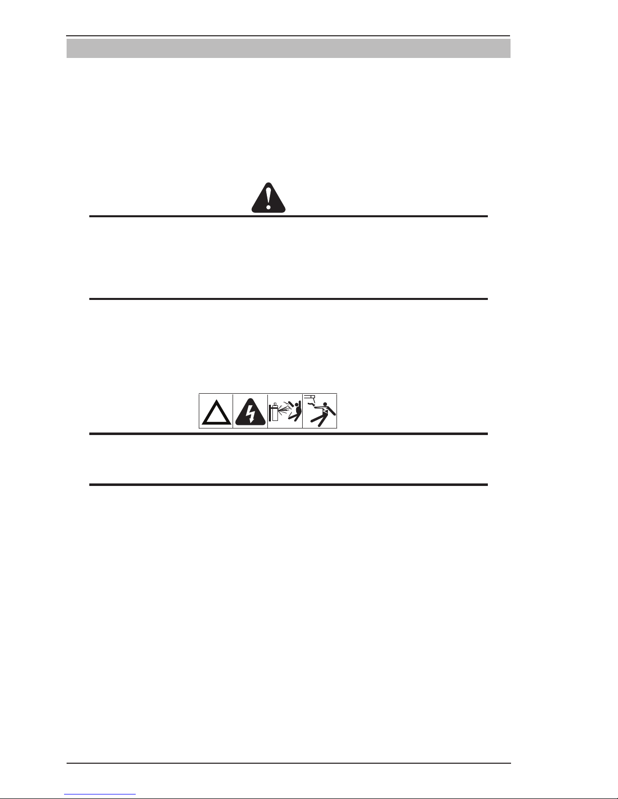
9. Slowly and carefully open the cylinder valve (Figure 3-5) until the maximum pressure shows on the
high pressure gauge.
Art # A-09828
Figure 3-9: Open Cylinder Valve
10. On all cylinders, except acetylene, open the valve completely to seal the valve packing. On gaugeless
regulators, the indicator will register the cylinder contents open.
11. On acetylene cylinders, open the valve 3/4 of a turn and no more than 1-1/2.
!
WARNING
Acetylene delivery pressure must not exceed 15 PSIG (103 kPa) or 30 PSIG (207 kPa). Acetylene
can dissociate (decompose with explosive violence) above these pressure limits.
CAUTION
Keep the cylinder valve wrench, if one is required, on the cylinder valve to turn off the cylinder
quickly, if necessary.
12. Attach the desired downstream equipment.
Page 34
INSTALLATION/SETUP 202 AC/DC INVERTER
INSTALLATION, OPERATION AND SETUP 3-16 Manual 0-5239
3.13 Setup for TIG (GTAW) Welding
A. Select Lift TIG or HF TIG mode with the process selection control (refer to Section 3.08.7 for further
information).
B. Connect the TIG Torch to the negative welding terminal (-). Welding current flows from the power source
via heavy duty bayonet type terminals. It is essential, however, that the male plug is inserted and turned
securely to achieve a sound electrical connection.
C. Connect the work lead to the positive welding terminal (+). Welding current flows from the Power Source
via heavy duty bayonet type terminals. It is essential, however, that the male plug is inserted and turned
securely to achieve a sound electrical connection.
CAUTION
Loose welding terminal connections can cause overheating and result in the male plug being fused
in the bayonet terminal.
D. Connect the TIG torch trigger switch via the 8 pin socket located on the front of the power source as shown
below. The TIG torch will require a trigger switch to operate in Lift TIG or HF TIG Mode.
NOTE
If the TIG torch has a remote TIG torch current control fitted then it will require to be connected to
the 8 pin socket. (Refer to section 3.08.2 Remote Control Socket for further information).
E. Fit the welding grade shielding gas regulator/flowmeter to the shielding gas cylinder (refer to Section 3.12)
then connect the shielding gas hose from the regulator/flowmeter outlet gas INLET on the rear of the 202
AC/DC Power Source. Connect the gas hose from the TIG torch to the gas OUTLET on the front of the 202
AC/DC Power Source.
!
WARNING
Before connecting the work clamp to the work make sure the mains power supply is switched off.
Secure the welding grade shielding gas cylinder in an upright position by chaining it to a suitable
stationary support to prevent falling or tipping.
Page 35
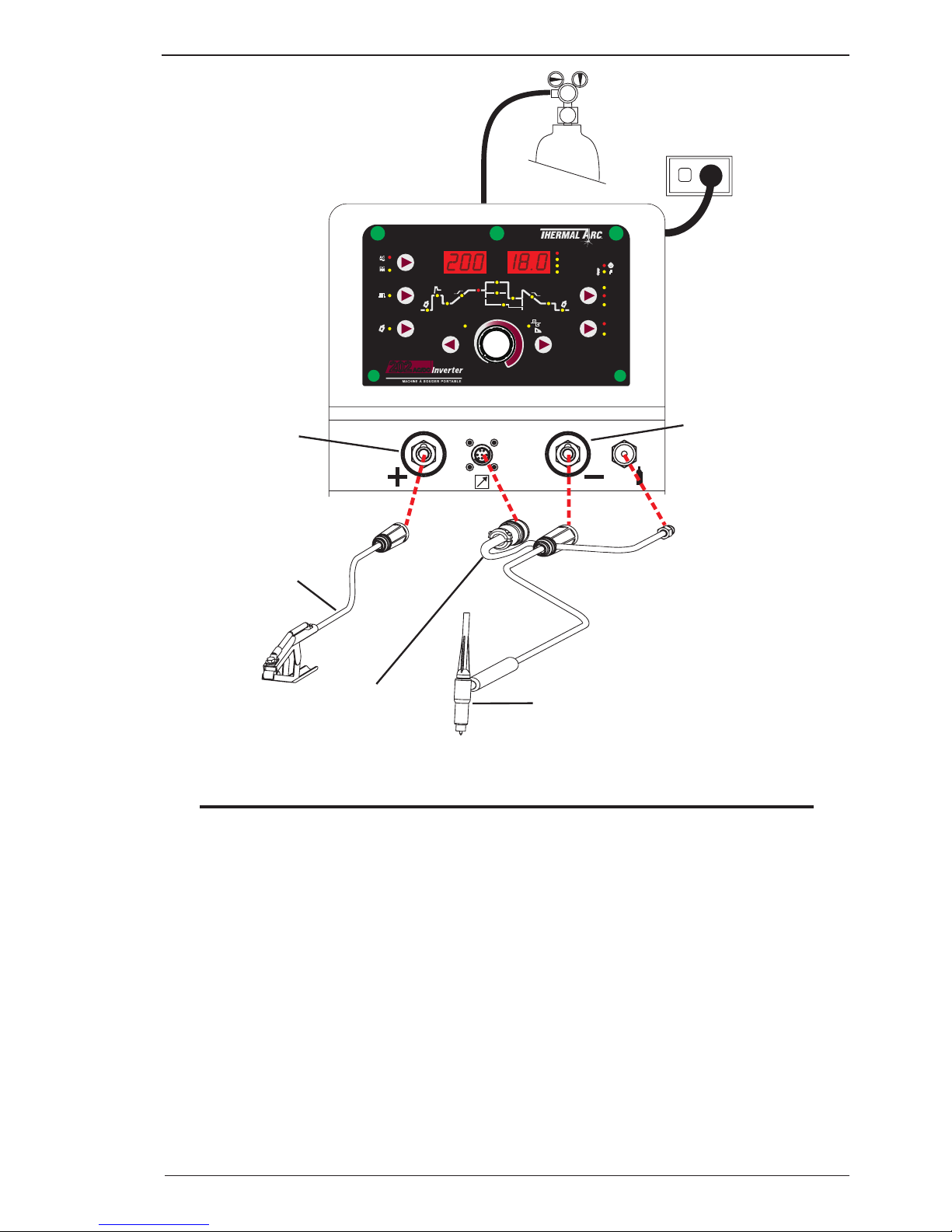
INSTALLATION/SETUP 202 AC/DC INVERTER
Manual 0-5239 3-17 INSTALLATION, OPERATION AND SETUP
8
Negative Welding
Terminal (-)
Work Lead
Positive Welding
Terminal (+)
8 Pin Control Socket
Tig Torch
A-11406
I
z
I
s
I
2
I
e
I
1
MODE
PULSE
PURGE
PROCESS
LIFT TIG
V
SEC
%
Hz
HF TIG
STICK
2T
4T
TRIGGER
BACK FORWARD
AC FREQUENCY
PORTABLE WELDING SYSTEM
WAVE BALANCE
ARC FORCE
Pre
Flow
Post
Flow
Initial
Current
Up
Slope
Down
Slope
Crater
Current
Base
Current
Frequency
f
w
Width
High Current
Low
Current
Hot
Start
t1
t2
202
AV
Figure 3-10: Setup for TIG Welding
NOTE
When the 202AC/DC is used with a Remote Foot Control, disconnect the foot control to allow max
current to be previewed / adjusted, then re connect foot control, max current that has been pre set
will be output when foot control is fully depressed during welding. The maximum current can also
be adjusted in welding operation when foot control is fully depressed. To avoid premature arcing,
please ensure the TIG Torch is located away from your work piece.
Page 36
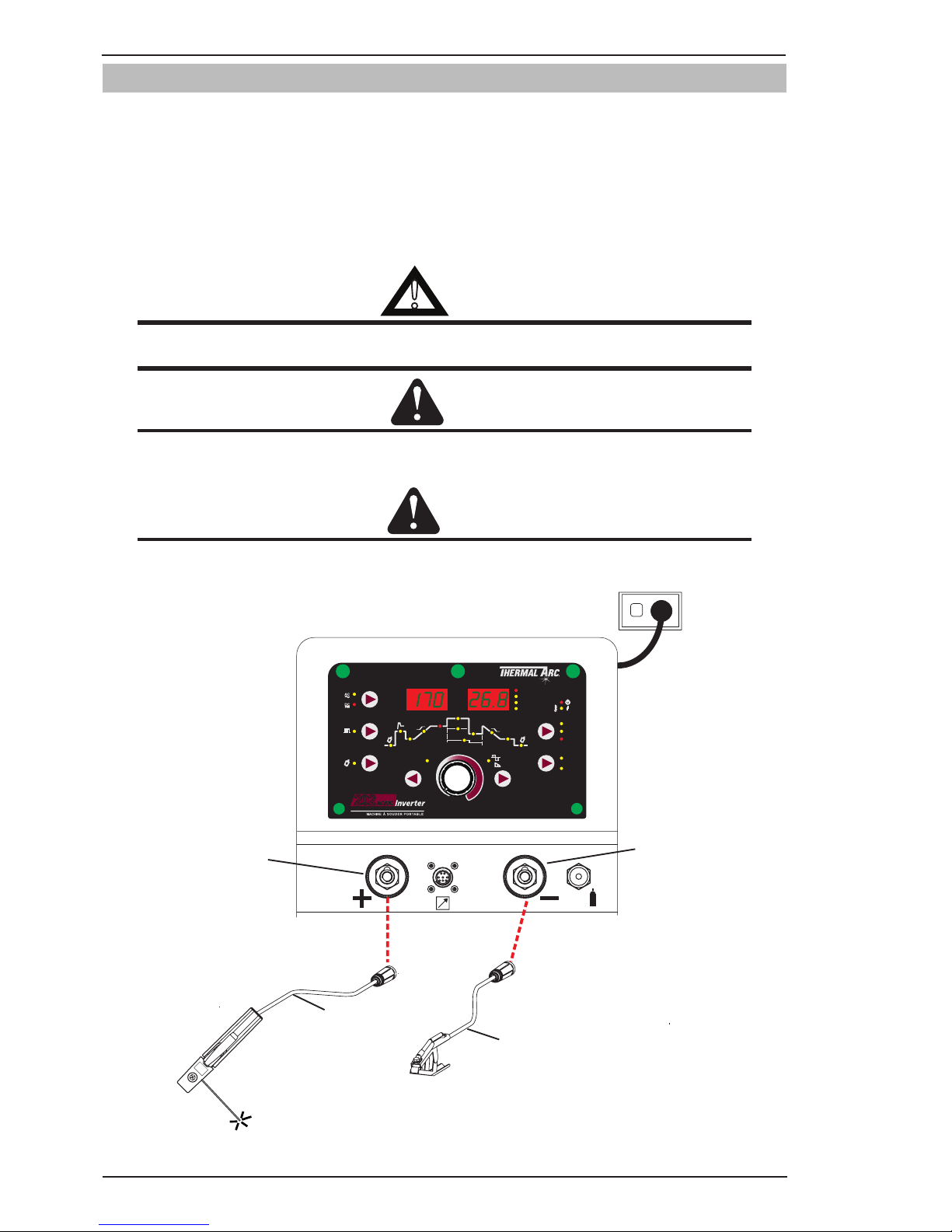
INSTALLATION/SETUP 202 AC/DC INVERTER
INSTALLATION, OPERATION AND SETUP 3-18 Manual 0-5239
3.14 Setup for STICK (MMA) Welding
A. Connect the Electrode Holder lead to the positive welding terminal (+). If in doubt, consult the electrode
manufacturer. Welding current flows from the Power Source via heavy duty bayonet type terminals. It is
essential, however, that the male plug is inserted and turned securely to achieve a sound electrical connection.
B. Connect the work lead to the negative welding terminal (-). If in doubt, consult the electrode manufacturer.
Welding current flows from the power source via heavy duty bayonet type terminals. It is essential, however,
that the male plug is inserted and turned securely to achieve a sound electrical connection.
C. Select STICK mode with the process selection control (refer to Section 3.08.7 for further information)
!
WARNING
Before connecting the work clamp to the work and inserting the electrode in the electrode holder
make sure the mains power supply is switched off.
CAUTION
Remove any packaging material prior to use. Do not block the air vents at the front or rear of the
Welding Power Source.
CAUTION
Loose welding terminal connections can cause overheating and result in the male plug being fused
in the bayonet terminal.
8
Negative Welding
Terminal (-)
Positive Welding
Terminal (+)
Electrode Holder
Work Lead
A-11407
200A
I
z
I
s
I
2
I
e
I
1
MODE
PULSE
PURGE
PROCESS
LIFT TIG
V
SEC
%
Hz
HF TIG
STICK
2T
4T
TRIGGER
BACK FORWARD
AC FREQUENCY
PORTABLEWELDING SYSTEM
WAVE BALANCE
ARC FORCE
Pre
Flow
Post
Flow
Initial
Current
Up
Slope
Down
Slope
Crater
Current
Base
Current
Frequency
f
w
Width
High Current
Low
Current
Hot
Start
t1
t2
202
AV
Figure 3-11: Setup for Manual Arc Welding.
Page 37

BASIC WELDING 202 AC/DC INVERTER
Manual 0-5239 4-1 BASIC WELDING GUIDE
SECTION 4:
BASIC WELDING GUIDE
4.01 Stick (MMA) Basic Welding Technique
Size of Electrode
The electrode size is determined by the thickness of metals being joined and can also be governed by the type
of welding machine available. Small welding machines will only provide sufficient current (amperage) to run
the smaller size electrodes.
For thin sections, it is necessary to use smaller electrodes otherwise the arc may burn holes through the job.
A little practice will soon establish the most suitable electrode for a given application.
Storage of Electrodes
Always store electrodes in a dry place and in their original containers.
Electrode Polarity
Electrodes are generally connected to the ELECTRODE HOLDER with the Electrode Holder connected positive
polarity. The WORK LEAD is connected negative polarity and is connected to the work piece. If in doubt consult
the electrode data sheet or your nearest Accredited Thermal Arc Distributor.
Effects of Stick Welding Various Materials
A. High Tensile and Alloy Steels
The two most prominent effects of welding these steels are the formation of a hardened zone in the weld
area, and, if suitable precautions are not taken, the occurrence in this zone of under-bead cracks. Hardened
zone and under-bead cracks in the weld area may be reduced by using the correct electrodes, preheating,
using higher current settings, using larger electrodes sizes, short runs for larger electrode deposits or
tempering in a furnace.
B. Manganese Steels
The effect on manganese steel of slow cooling from high temperatures is to embrittle it. For this reason
it is absolutely essential to keep manganese steel cool during welding by quenching after each weld or
skip welding to distribute the heat.
C. Cast Iron
Most types of cast iron, except white iron, are weldable. White iron, because of its extreme brittleness,
generally cracks when attempts are made to weld it. Trouble may also be experienced when welding whiteheart malleable, due to the porosity caused by gas held in this type of iron.
D. Copper and Alloys
The most important factor is the high rate of heat conductivity of copper, making pre-heating of heavy
sections necessary to give proper fusion of weld and base metal.
E. Types of Electrodes
Arc Welding electrodes are classified into a number of groups depending on their applications. There are
a great number of electrodes used for specialized industrial purposes which are not of particular interest
for everyday general work. These include some low hydrogen types for high tensile steel, cellulose types
for welding large diameter pipes, etc The range of electrodes dealt with in this publication will cover the
vast majority of applications likely to be encountered; are all easy to use.
Page 38
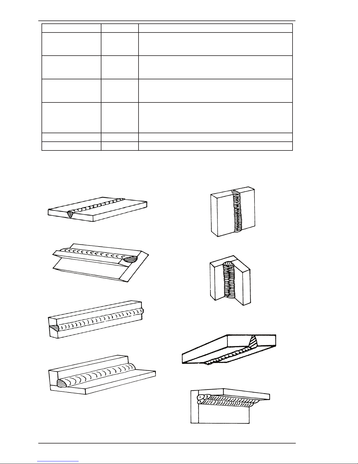
202 AC/DC INVERTER BASIC WELDING
BASIC WELDING GUIDE 4-2 Manual 0-5239
Art # A-07687
Figure 4-1: Flat Position, Down Hand Butt Weld
Art # A-07688
Figure 4-2: Flat Position, Gravity Fillet Weld
Art # A-07689
Figure 4-3: Horizontal Position, Butt Weld
Art # A-07690
Figure 4-4: Horizontal-Vertical (HV) Position
Metal Being Joined Electrode Comments
Mild Steel E6011 This electrode is used for all-position welding or for welding
on rusty, dirty, less-than-new metal. It has a deep, penetrating
arc and is often the first choice for repair or maintenance work.
Mild Steel E6013 This all-position, electrode is used for welding clean, new sheet
metal. Its soft arc has minimal spatter, moderate penetration and
an easy-to-clean slag.
Mild Steel E7014 All positional, ease to use electrode for use on thicker steel than
E6013. Especially suitable sheet metal lap joints and fillet welds,
general purpose plate welding.
Mild Steel E7018 A low-hydrogen, all-position electrode used when quality is an
issue or for hard-to-weld metals. It has the capability of producing
more uniform weld metal, which has better impact properties at
low temperatures.
Cast Iron Eni-Cl Suitable for joining all cast irons except white cast iron.
Stainless Steel E318L-16 High corrosion resistances. Ideal for dairy work etc.
Welding Position
The electrodes dealt with in this publication can be used in most positions, i.e. they are suitable for welding in
flat, horizontal, vertical and overhead positions. Numerous applications call for welds to be made in positions
intermediate between these. Some of the common types of welds are shown in Figures 4-5 through 4-12.
Art A-07691
Figure 4-5: Vertical Position, Butt Weld
Art # A-07692
Figure 4-6: Vertical Position, Fillet Weld
Art# A-07693
Figure 4-7: Overhead Position, Butt Weld
Art # A-07694
Figure 4-8: Overhead Position, Fillet Weld
Page 39
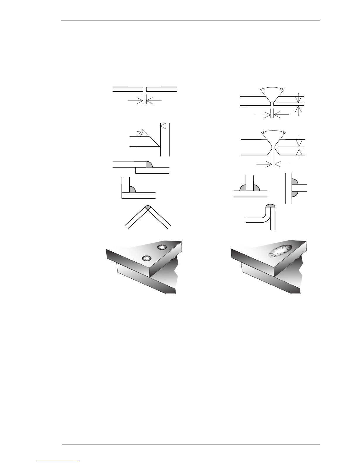
BASIC WELDING 202 AC/DC INVERTER
Manual 0-5239 4-3 BASIC WELDING GUIDE
Joint Preparations
In many cases, it will be possible to weld steel sections without any special preparation. For heavier sections
and for repair work on castings, etc., it will be necessary to cut or grind an angle between the pieces being
joined to ensure proper penetration of the weld metal and to produce sound joints.
In general, surfaces being welded should be clean and free of rust, scale, dirt, grease, etc. Slag should be
removed from oxy-cut surfaces. Typical joint designs are shown in Figure 4-9.
Gap varies from
1.6mm (1/16”) to 4.8mm (3/16”)
depending on plate thickness
Joint
Open Square Butt
1.6mm (1/16” ) max
1.6mm (1/16”)
Single Vee Butt Joint
Not less than
70°
Double Vee Butt Joint
1.6mm (1/16”)
Lap Joint
Tee Joints
(Fillet both sides of the
joint)
Edge Joint
Fillet Joint
Corner Weld
Plug Weld Plug Weld
Not less than
70°
Single Vee Butt Joint
Not less than
45°
1.6mm (1/16”) max
Art # A-07695_AE
Figure 4-9: Typical Joint Designs for Arc Welding
Arc Welding Technique - A Word to Beginners
For those who have not yet done any welding, the simplest way to commence is to run beads on a piece of
scrap plate. Use mild steel plate about 6.0mm thick and a 3.2mm electrode. Clean any paint, loose scale or
grease off the plate and set it firmly on the work bench so that welding can be carried out in the downhand
position. Make sure that the work clamp is making good electrical contact with the work, either directly or
through the work table. For light gauge material, always clamp the work lead directly to the job, otherwise a
poor circuit will probably result.
The Welder
Place yourself in a comfortable position before beginning to weld. Get a seat of suitable height and do as
much work as possible sitting down. Don't hold your body tense. A taut attitude of mind and a tensed body
will soon make you feel tired. Relax and you will find that the job becomes much easier. You can add much to
your peace of mind by wearing a leather apron and gauntlets. You won't be worrying then about being burnt
or sparks setting alight to your clothes.
Page 40

202 AC/DC INVERTER BASIC WELDING
BASIC WELDING GUIDE 4-4 Manual 0-5239
Place the work so that the direction of welding is across, rather than to or from, your body. The electrode
holder lead should be clear of any obstruction so that you can move your arm freely along as the electrode
burns down. If the lead is slung over your shoulder, it allows greater freedom of movement and takes a lot of
weight off your hand. Be sure the insulation on your cable and electrode holder is not faulty, otherwise you
are risking an electric shock.
Striking the Arc
Practice this on a piece of scrap plate before going on to more exacting work. You may at first experience
difficulty due to the tip of the electrode "sticking" to the work piece. This is caused by making too heavy a
contact with the work and failing to withdraw the electrode quickly enough. A low amperage will accentuate it.
This freezing-on of the tip may be overcome by scratching the electrode along the plate surface in the same
way as a match is struck. As soon as the arc is established, maintain a 1.6mm to 3.2mm gap between the
burning electrode end and the parent metal. Draw the electrode slowly along as it melts down.
Another difficulty you may meet is the tendency, after the arc is struck, to withdraw the electrode so far that
the arc is broken again. A little practice will soon remedy both of these faults.
Art # A-07696_AB
20°
1.6 mm (1/16”)
Figure 4-10: Striking an Arc
Arc Length
The securing of an arc length necessary to produce a neat weld soon becomes almost automatic. You will
find that a long arc produces more heat. A very long arc produces a crackling or spluttering noise and the
weld metal comes across in large, irregular blobs. The weld bead is flattened and spatter increases. A short
arc is essential if a high quality weld is to be obtained although if it is too short there is the danger of it being
blanketed by slag and the electrode tip being solidified in. If this should happen, give the electrode a quick
twist back over the weld to detach it.
Rate of Travel
After the arc is struck, your next concern is to maintain it, and this requires moving the electrode tip towards
the molten pool at the same rate as it is melting away. At the same time, the electrode has to move along the
plate to form a bead. The electrode is directed at the weld pool at about 20º from the vertical. The rate of travel
has to be adjusted so that a well-formed bead is produced.
If the travel is too fast, the bead will be narrow and strung out and may even be broken up into individual
globules. If the travel is too slow, the weld metal piles up and the bead will be too large.
Making Welded Joints
Having attained some skill in the handling of an electrode, you will be ready to go on to make up welded joints.
A. Butt Welds
Set up two plates with their edges parallel, as shown in Figure 4-11, allowing 1.6mm to 2.4mm gap between
them and tack weld at both ends. This is to prevent contraction stresses from the cooling weld metal
pulling the plates out of alignment. Plates thicker than 6.0mm should have their mating edges bevelled to
form a 70º to 90º included angle. This allows full penetration of the weld metal to the root.
Page 41
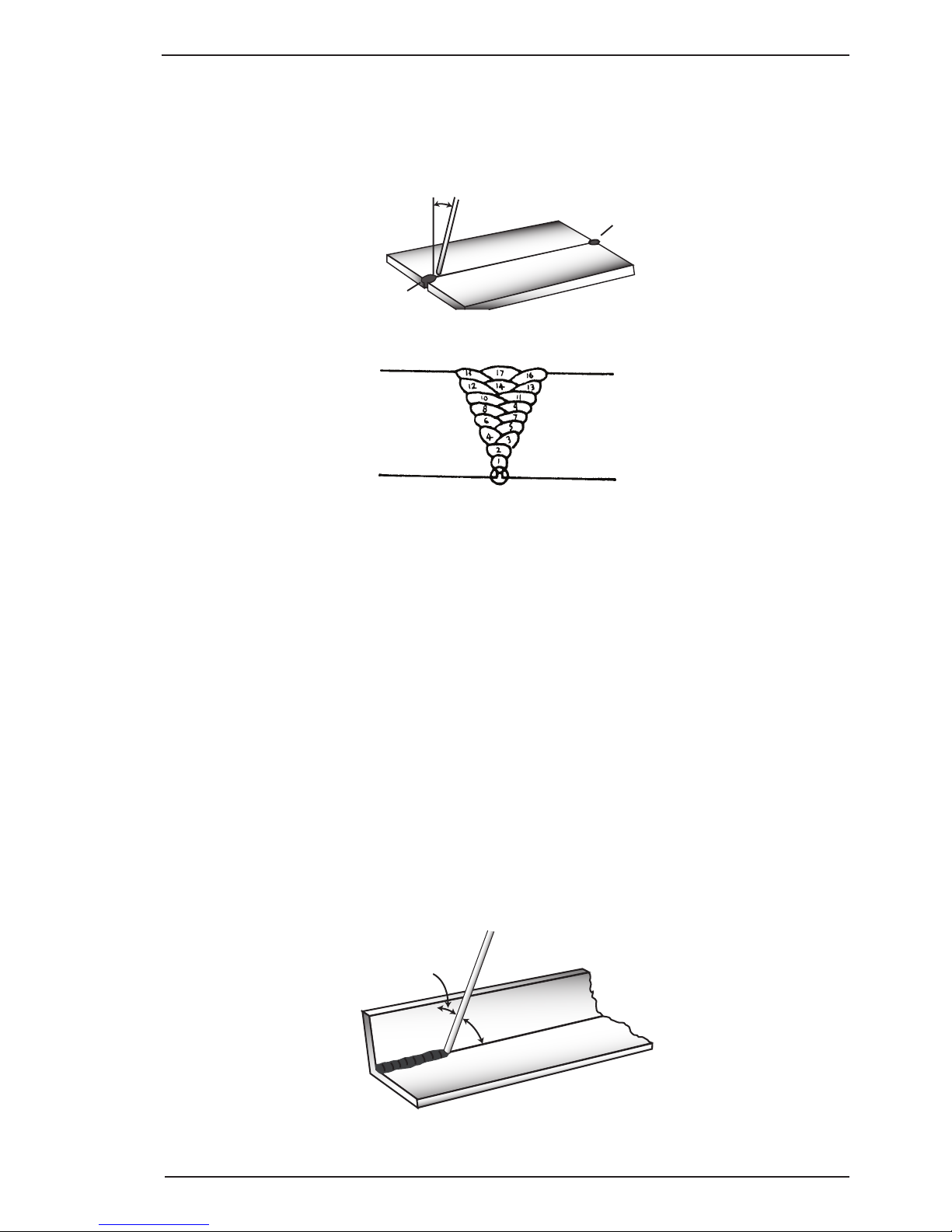
BASIC WELDING 202 AC/DC INVERTER
Manual 0-5239 4-5 BASIC WELDING GUIDE
Do not weave the electrode, but maintain a steady rate of travel along the joint sufficient to produce a
well-formed bead. At first you may notice a tendency for undercut to form, but keeping the arc length
short, the angle of the electrode at about 20º from vertical, and the rate of travel not too fast, will help
eliminate this. The electrode needs to be moved along fast enough to prevent the slag pool from getting
ahead of the arc. To complete the joint in thin plate, turn the job over, clean the slag out of the back and
deposit a similar weld.
Art # A-07697_AB
Tack Weld
20°-30°
Electrode
Tack Weld
Figure 4-11: Butt Weld
Art # A-07698
Figure 4-12: Weld Build up Sequence
Heavy plate will require several runs to complete the joint. After completing the first run, chip the slag
out and clean the weld with a wire brush. It is important to do this to prevent slag being trapped by the
second run. Subsequent runs are then deposited using either a weave technique or single beads laid down
in the sequence shown in Figure 4-12. The width of weave should not be more than three times the core
wire diameter of the electrode. When the joint is completely filled, the back is either machined, ground or
gouged out to remove slag which may be trapped in the root, and to prepare a suitable joint for depositing
the backing run. If a backing bar is used, it is not usually necessary to remove this, since it serves a similar
purpose to the backing run in securing proper fusion at the root of the weld.
B. Fillet Welds
These are welds of approximately triangular cross-section made by depositing metal in the corner of two
faces meeting at right angles. Refer to Figure 4-4.
A piece of angle iron is a suitable specimen with which to begin, or two lengths of strip steel may be tacked
together at right angles. This is known as a horizontal-vertical (HV) fillet. Strike the arc and immediately
bring the electrode to a position perpendicular to the line of the fillet and about 45º from the vertical. Some
electrodes require to be sloped about 20º away from the perpendicular position to prevent slag from running
ahead of the weld. Refer to Figure 4-13. Do not attempt to build up much larger than 6.4mm width with
a 3.2mm electrode, otherwise the weld metal tends to sag towards the base, and undercut forms on the
vertical leg. Multi-runs can be made as shown in Figure 4-14. Weaving in HV fillet welds is undesirable.
Art # A-07699_AB
45° from
vertical
60° - 70° from line
of weld
Figure 4-13: Electrode Position for HV Fillet Weld
Page 42
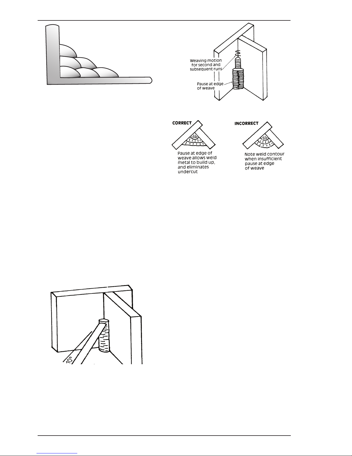
202 AC/DC INVERTER BASIC WELDING
BASIC WELDING GUIDE 4-6 Manual 0-5239
Art # A-07700_AB
1
2
3
4
5
6
Figure 4-`14: Multi-runs in HV Fillet Weld
C. Vertical Welds
1. Vertical Up
Tack weld a three feet length of angle iron
to your work bench in an upright position.
Make yourself comfortable on a seat in front
of the job and strike the arc in the corner of
the fillet. The electrode needs to be about 10º
from the horizontal to enable a good bead to
be deposited. Refer Figure 4-15. Use a short
arc, and do not attempt to weave on the first
run. When the first run has been completed
de-slag the weld deposit and begin the second
run at the bottom. This time a slight weaving
motion is necessary to cover the first run
and obtain good fusion at the edges. At the
completion of each side motion, pause for a
moment to allow weld metal to build up at
the edges, otherwise undercut will form and
too much metal will accumulate in the centre
of the weld. Figure 4-16 illustrates multi-run
technique and Figure 4-17 shows the effects of
pausing at the edge of weave and of weaving
too rapidly.
Art # A-07701
Figure 4-15: Single Run Vertical Fillet Weld
Art # A-07702
Figure 4-16: Multi Run Vertical Fillet Weld
Art # A-07703
Figure 4-17: Examples of Vertical Fillet Welds
2. Vertical Down
Use a 3.2mm electrode at 100 amps. The tip
of the electrode is held in light contact with
the work and the speed of downward travel is
regulated so that the tip of the electrode just
keeps ahead of the slag. The electrode should
point upwards at an angle of about 45º.
3. Overhead Welds
Apart from the rather awkward position
necessary, overhead welding is not much
more difficult that downhand welding. Set up a
specimen for overhead welding by first tacking
a length of angle iron at right angles to another
piece of angle iron or a length of waste pipe.
Then tack this to the work bench or hold in a
vice so that the specimen is positioned in the
overhead position as shown in the sketch. The
electrode is held at 45º to the horizontal and
tilted 10º in the line of travel (Figure 4-18). The
tip of the electrode may be touched lightly on
the metal, which helps to give a steady run. A
weave technique is not advisable for overhead
fillet welds.
Page 43
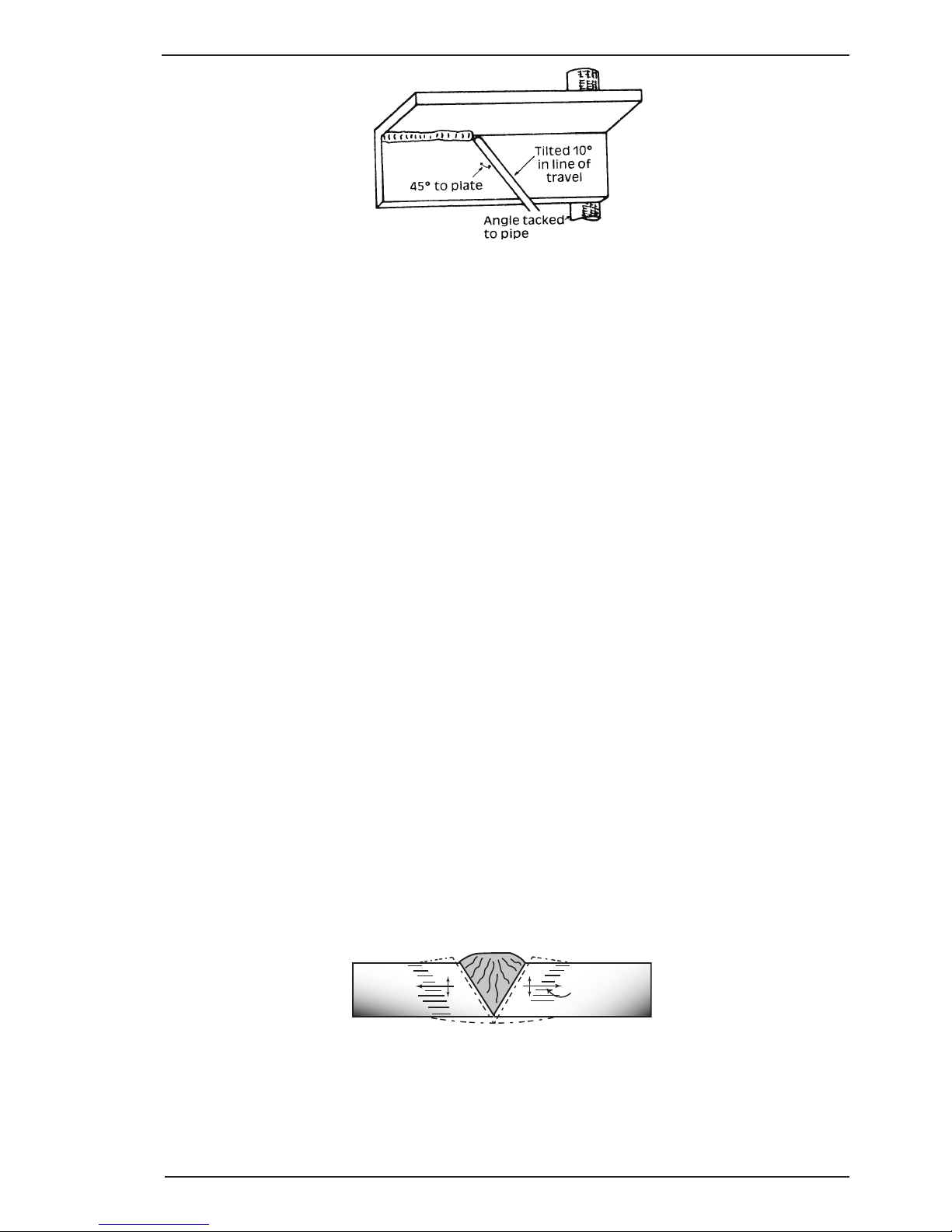
BASIC WELDING 202 AC/DC INVERTER
Manual 0-5239 4-7 BASIC WELDING GUIDE
Art # A-07704
Figure 4-18: Overhead Fillet Weld
Distortion
Distortion in some degree is present in all forms of welding. In many cases it is so small that it is barely
perceptible, but in other cases allowance has to be made before welding commences for the distortion that
will subsequently occur. The study of distortion is so complex that only a brief outline can be attempted hear.
The Cause of Distortion
Distortion is caused by:
A. Contraction of Weld Metal:
Molten steel shrinks approximately 11 per cent in volume on cooling to room temperature. This means
that a cube of molten metal would contract approximately 2.2 per cent in each of its three dimensions. In
a welded joint, the metal becomes attached to the side of the joint and cannot contract freely. Therefore,
cooling causes the weld metal to flow plastically, that is, the weld itself has to stretch if it is to overcome
the effect of shrinking volume and still be attached to the edge of the joint. If the restraint is very great,
as, for example, in a heavy section of plate, the weld metal may crack. Even in cases where the weld
metal does not crack, there will still remain stresses "Locked-up" in the structure. If the joint material is
relatively weak, for example, a butt joint in 2.0mm sheet, the contracting weld metal may cause the sheet
to become distorted.
B. Expansion and Contraction of Parent Metal in the Fusion Zone:
While welding is proceeding, a relatively small volume of the adjacent plate material is heated to a very
high temperature and attempts to expand in all directions. It is able to do this freely at right angles to the
surface of the plate (i.e., "through the weld", but when it attempts to expand "across the weld" or "along the
weld", it meets considerable resistance, and to fulfil the desire for continued expansion, it has to deform
plastically, that is, the metal adjacent to the weld is at a high temperature and hence rather soft, and, by
expanding, pushes against the cooler, harder metal further away, and tends to bulge (or is "upset". When
the weld area begins to cool, the "upset" metal attempts to contract as much as it expanded, but, because
it has been "upset" it does not resume its former shape, and the contraction of the new shape exerts a
strong pull on adjacent metal. Several things can then happen.
The metal in the weld area is stretched (plastic deformation), the job may be pulled out of shape by the
powerful contraction stresses (distortion), or the weld may crack, in any case, there will remain "lockedup" stresses in the job. Figures 4-19 and 4- 20 illustrate how distortion is created.
Art # A-07705_AB
Hot
Hot
Weld
Upsetting
Expansion with
compression
Cool
Figure 4-19: Parent Metal Expansion
Page 44
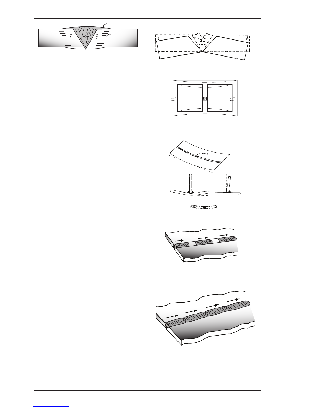
202 AC/DC INVERTER BASIC WELDING
BASIC WELDING GUIDE 4-8 Manual 0-5239
Art # A-07706_AB
Weld
Permanent Upset
Contraction
with tension
Figure 4-20: Parent Metal Contraction
Overcoming Distortion Effects
There are several methods of minimizing distortion
effects.
A. Peening
This is done by hammering the weld while it is
still hot. The weld metal is flattened slightly and
because of this the tensile stresses are reduced
a little. The effect of peening is relatively shallow,
and is not advisable on the last layer.
B. Distribution of Stresses
Distortion may be reduced by selecting a welding
sequence which will distribute the stresses
suitably so that they tend to cancel each other out.
See Figures 4-20 through 4-23 for various weld
sequences. Choice of a suitable weld sequence is
probably the most effective method of overcoming
distortion, although an unsuitable sequence may
exaggerate it. Simultaneous welding of both sides
of a joint by two welders is often successful in
eliminating distortion.
C. Restraint of Parts
Forcible restraint of the components being welded
is often used to prevent distortion. Jigs, positions,
and tack welds are methods employed with this
in view.
D. Presetting
It is possible in some cases to tell from past
experience or to find by trial and error (or less
frequently, to calculate) how much distortion will
take place in a given welded structure. By correct
pre-setting of the components to be welded,
constructional stresses can be made to pull the
parts into correct alignment. A simple example is
shown in Figure 4-21.
E. Preheating
Suitable preheating of parts of the structure other
than the area to be welded can be sometimes used
to reduce distortion. Figure 4-22 shows a simple
application. By removing the heating source from
b and c as soon as welding is completed, the
sections b and c will contract at a similar rate,
thus reducing distortion.
Art # A-07707
Figure 4-21: Principle of Presetting
Art # A-07708
B
PreheatPreheat
Dotted lines show effect if no preheat is used
Weld
C
Figure 4-22: Reduction of Distortion by Preheating
Art # A-07709
Figure 4-23: Examples of Distortion
Art # A-07710_AB
1
Block Sequence.
The spaces between the welds are
filled in when the welds are cool.
2
3
Figure 4-24: Welding Sequence
4
3
2
1
Figure 4-25: Step back Sequence
Page 45
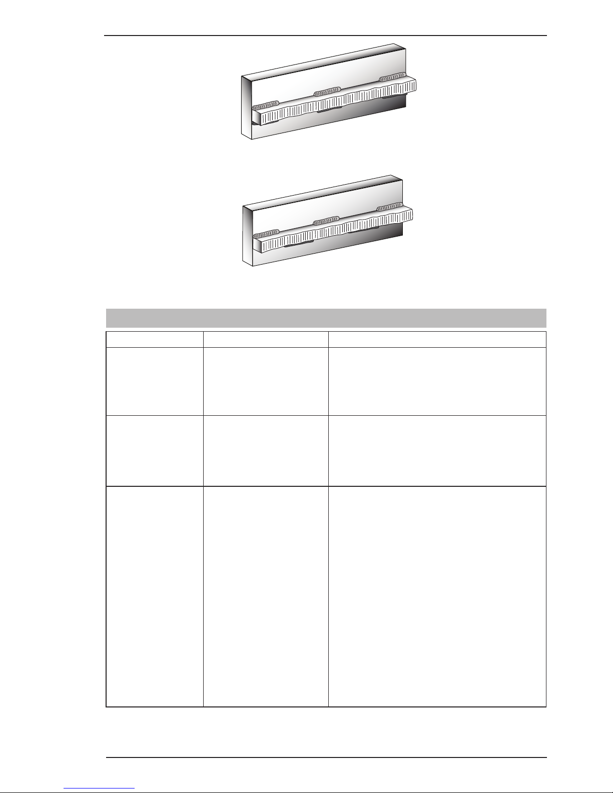
BASIC WELDING 202 AC/DC INVERTER
Manual 0-5239 4-9 BASIC WELDING GUIDE
Art # A-07428_AB
Figure 4-26: Chain Intermittent Welding
Art # A-07713_AB
Figure 4-27: Staggered Intermittent Welding
4.02 Stick (MMA) Welding Troubleshooting
FAULT CAUSE REMEDY
1 Welding current
varying
ARC FORCE control knob
is set at a value that
causes the welding current
to vary excessively with
the arc length.
Reduce the ARC FORCE control knob until welding current is reasonably constant while prohibiting the electrode from sticking to the work piece
when you “dig” the electrode into the workpiece.
2 A gap is left by
failure of the weld
metal to fill the
root of the weld.
A Welding current too low A Increase welding current.
B Electrode too large for
joint.
B Use smaller diameter electrode.
C Insufficient gap. C Allow wider gap.
3 Non-metallic par-
ticles are trapped
in the weld metal.
A Non-metallic particles may
be trapped in undercut
from previous run.
A If a bad undercut is present clean slag bout and
cover with a run from a smaller gauge electrode.
B Joint preparation too
restricted.
B Allow for adequate penetration and room for
cleaning out the slag.
C Irregular deposits allow
slag to be trapped.
C If very bad, chip or grind out irregularities.
D Lack of penetration with
slag trapped beneath weld
bead.
D Use smaller electrode with sufficient current to
give adequate penetration. Use suitable tools to
remove all slag from comers.
E Rust or mill scale is pre-
venting full fusion.
E Clean joint before welding.
F Wrong electrode for posi-
tion in which welding is
done.
F Use electrodes designed for position in which
welding is done, otherwise proper control of slag
is difficult.
Page 46
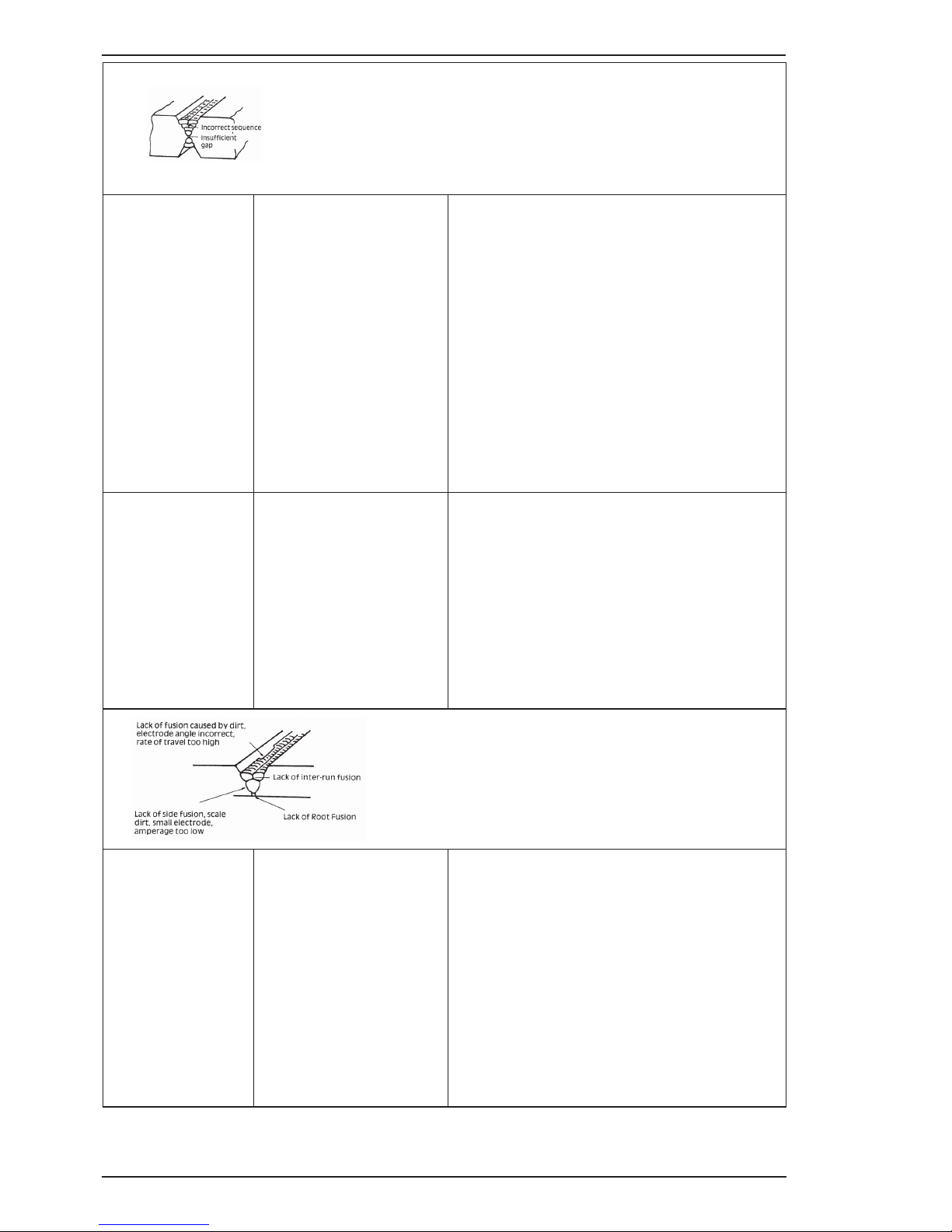
202 AC/DC INVERTER BASIC WELDING
BASIC WELDING GUIDE 4-10 Manual 0-5239
Art: A-04971
Figure 1-Example of insufficient gap or incorrect sequence
4 A groove has been
formed in the base
metal adjacent to
the toe of a weld
and has not been
filled by the weld
metal (undercut).
A Welding current is too
high.
A Reduce welding current.
B Welding arc is too long. B Reduce the length of the welding arc.
C Angle of the electrode is
incorrect.
C Electrode should not be inclined less than 45° to
the vertical face.
D Joint preparation does not
allow correct electrode
angle.
D Allow more room in joint for manipulation of the
electrode.
E Electrode too large for
joint.
E Use smaller gauge electrode.
F Insufficient deposit time at
edge of weave.
F Pause for a moment at edge of weave to allow
weld metal buildup.
5 Portions of the
weld run do not
fuse to the surface
of the metal or
edge of the joint.
A Small electrodes used on
heavy cold plate.
A Use larger electrodes and preheat the plate.
B Welding current is too low. B Increase welding current.
C Wrong electrode angle. C Adjust angle so the welding arc is directed more
into the base metal.
D Travel speed of electrode
is too high.
D Reduce travel speed of electrode.
E Scale or dirt on joint
surface.
E Clean surface before welding.
Art: A-04972
Figure 2: Example of Lack of Fusion
6 Gas pockets or
voids in weld
metal (porosity)
A High levels of sulphur in
steel.
A Use an electrode that is designed for high sul-
phur steels.
B Electrodes are damp. B Dry electrodes before use.
C Welding current is too
high.
C Reduce welding current.
D Surface impurities such as
oil, grease, paint, etc.
D Clean joint before welding.
E Welding in a windy envi-
ronment.
E Shield the weld area from the wind.
F Electrode damaged ie flux
coating incomplete.
F Discard damaged electrodes and only use elec-
trodes with a complete flux coating.
Page 47
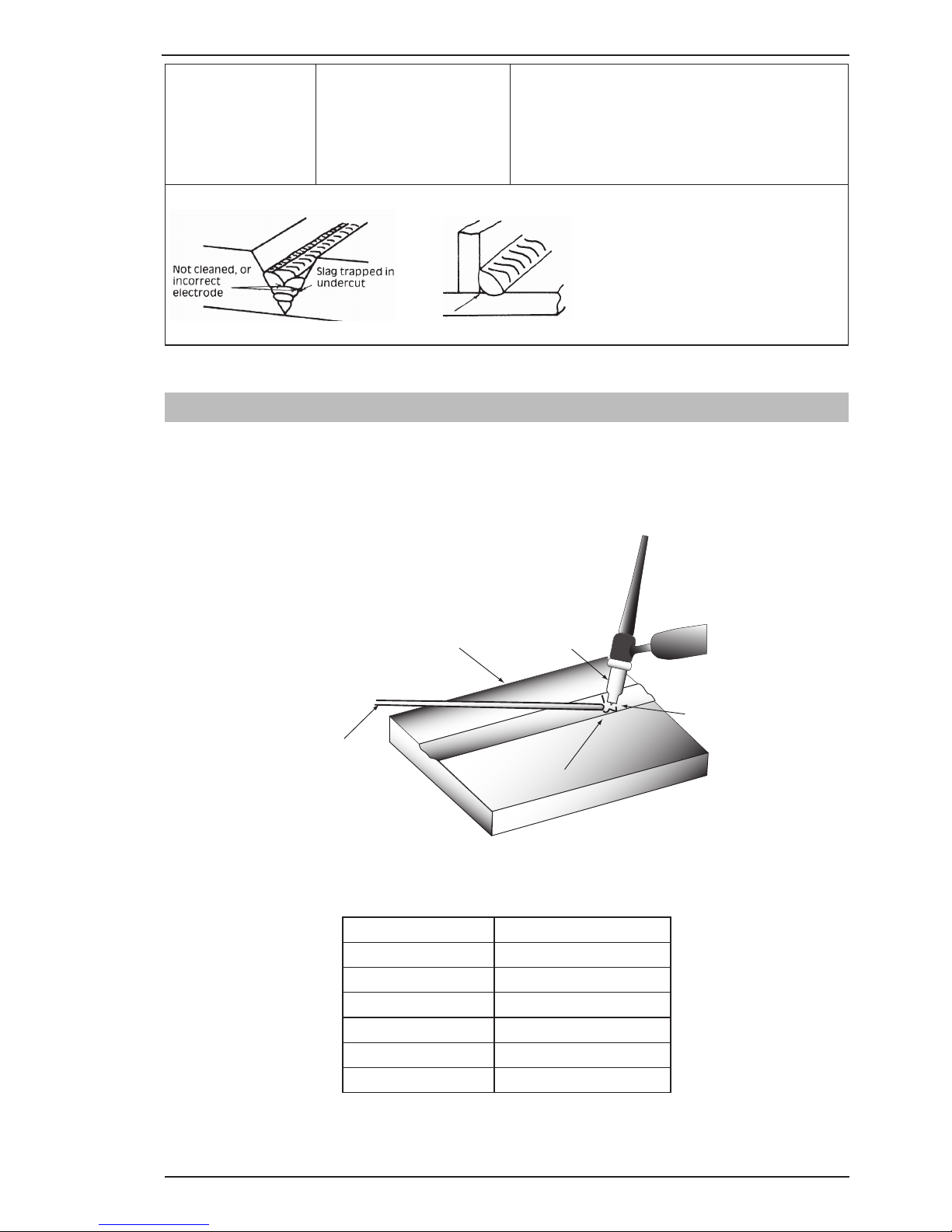
BASIC WELDING 202 AC/DC INVERTER
Manual 0-5239 4-11 BASIC WELDING GUIDE
7 Crack occurring in
weld metal soon
after solidification
commences
A Rigidity of joint. A Redesign to relieve weld joint of severe stresses
or use crack resistance electrodes.
B Insufficient throat thick-
ness.
B Travel slightly slower to allow greater build up in
throat.
C Weld current is too high. C Decrease welding current.
Art: A-04973
Figure 3: Example of Slag Inclusion
Table 4-2: Welding Problems MMA (Stick)
4.03 TIG (GTAW) Basic Welding Technique
Gas Tungsten Arc Welding (GTAW) or TIG (Tungsten Inert Gas) as it is commonly referred to, is a welding
process in which fusion is produced by an electric arc that is established between a single tungsten (nonconsumable) electrode and the work piece. Shielding is obtained from a welding grade shielding gas or welding
grade shielding gas mixture which is generally Argon based. A filler metal may also be added manually in some
circumstances depending on the welding application.
Welds Made With or Without
Addition of Filler Metal
Work Piece
Can Be Any Commercial
Metal
Gas Cup
Either Ceramic,
High-lmpact or
Water Cooled
Metal
Inert Gas
Shields Electrode
and Weld Puddle
Tungsten Electrode
Non-Consumable
A-09658_AB
Figure 4-28: TIG Welding Application Shot
Tungsten Electrode Current Ranges
Electrode Diameter DC Current (Amps)
0.040” (1.0mm) 30-60
1/16” (1.6mm) 60-115
3/32” (2.4mm) 100-165
1/8” (3.2mm) 135-200
5/32” (4.0mm) 190-280
3/16” (4.8mm) 250-340
Table 4-3: Current Ranges for Various Tungsten Electrode Sizes
Page 48

202 AC/DC INVERTER BASIC WELDING
BASIC WELDING GUIDE 4-12 Manual 0-5239
Guide for Selecting Filler Wire Diameter
Filler Wire Diameter DC Current Range (Amps)
1/16” (1.6mm) 20-90
3/32” (2.4mm) 65-115
1/8” (3.2mm) 100-165
3/16” (4.8mm) 200-350
Table 4-4: Filler Wire Selection Guide
Tungsten Electrode Types
Electrode Type
(Ground Finish)
Welding Application Features Colour Code
Thoriated 2%
DC welding of mild
steel, stainless steel
and copper
Excellent arc starting,
Long life, High current
carrying capacity
Red
Zirconated 1%
High quality AC welding of aluminium,
magnesium and their
alloys.
Self cleaning, Long
life, Maintains balled
end, High current carrying capacity.
White
Ceriated 2%
AC & DC welding of
mild steel, stainless
steel, copper, aluminium, magnesium and
their alloys
Longer life, More
stable arc, Easier
starting, Wider current
range, Narrower more
concentrated arc.
Grey
Table 4-5 Tungsten Electrode Types
Base Metal
Thickness
AC Current for
Aluminium
Tungsten
Electrode
Diameter
Filler Rod Diameter
(if required)
Argon Gas
Flow Rate
JOINT
TYPE
1/16”
1.6 mm
60-80
70-90
1/16”
1.6 mm
1/16”
1.6 mm
15 CFM
7LPM
Butt/Corner
Lap/Fillet
1/8”
3.2 mm
125-145
140-160
3/32”
2.4 mm
1/16”-3/32”
1.6mm-2.4mm
17CFM
8LPM
Butt/Corner
Lap/Fillet
Table 4-6 Aluminium Welding Material
Page 49
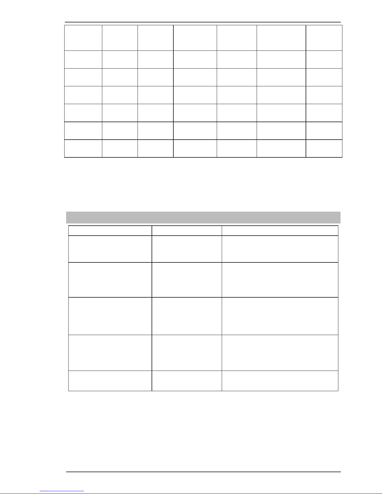
BASIC WELDING 202 AC/DC INVERTER
Manual 0-5239 4-13 BASIC WELDING GUIDE
Base Metal
Thickness
DC Current
for Mild
Steel
DC Current
for Stainless
Steel
Tungsten
Electrode
Diameter
Filler Rod
Diameter (if
required)
Argon Gas Flow
Rate
Joint Type
0.040”
1.0mm
35-45
40-50
20-30
25-35
0.040”
1.0mm
1/16”
1.6mm
10 CFH(5 LPM) Butt/Corner
Lap/Fillet
0.045”
1.2mm
45-55
50-60
30-45
35-50
0.040”
1.0mm
1/16”
1.6mm
13 CFH(6 LPM) Butt/Corner
Lap/Fillet
1/16”
1.6mm
60-70
70-90
40-60
50-70
1/16”
1.6mm
1/16”
1.6mm
15 CFH(7 LPM) Butt/Corner
Lap/Fillet
1/8”
3.2mm
80-100
90-115
65-85
90-110
1/16”
1.6mm
3/32”
2.4mm
15 CFH(7 LPM) Butt/Corner
Lap/Fillet
3/16”
4.8mm
115-135
140-165
100-125
125-150
3/32”
2.4mm
1/8”
3.2mm
21 CFH(10 LPM) Butt/Corner
Lap/Fillet
1/4”
6.4mm
160-175
170-200
135-160
160-180
1/8”
3.2mm
5/32”
4.0mm
21 CFH(10 LPM) Butt/Corner
Lap/Fillet
Table 4-7 Welding Rate
TIG Welding is generally regarded as a specialised process that requires operator competency. While many of
the principles outlined in the previous Arc Welding section are applicable a comprehensive outline of the TIG
Welding process is outside the scope of this Operating Manual. For further information please refer to www.
victortechnologies.com or contact Thermal Arc.
4.04 TIG (GTAW) Welding Problems
FAULT CAUSE REMEDY
1 Excessive bead build up or
poor penetration or poor
fusion at edges of weld.
Welding current is too
low
Increase weld current and/or faulty joint
preparation.
2 Weld bead too wide and
flat or undercut at edges
of weld or excessive burn
through.
Welding current is too
high
Decrease weld current.
3 Weld bead too small or
insufficient penetration or
ripples in bead are widely
spaced apart.
Travel speed too fast Reduce travel speed.
4 Weld bead too wide or
excessive bead build up or
excessive penetration in
butt joint.
Travel speed too slow Increase travel speed.
5 Uneven leg length in fillet
joint
Wrong placement of
filler rod
Re-position filler rod.
Page 50

202 AC/DC INVERTER BASIC WELDING
BASIC WELDING GUIDE 4-14 Manual 0-5239
6 Electrode melts or oxidises
when an arc is struck.
A Torch lead connected
to positive welding
terminal.
A Connect torch lead to negative welding
terminal.
B No gas flowing to weld-
ing region.
B Check the gas lines for kinks or breaks
and gas cylinder contents.
C Torch is clogged with
dust or dirt.
C Clean torch.
D Gas hose is cut. D Replace gas hose.
E Gas passage contains
impurities.
E Disconnect gas hose from the rear of
Power Source then raise gas pressure
and blow out impurities.
F Gas regulator turned
off.
F Turn on.
G The electrode is too
small for the welding
current.
G Increase electrode diameter or reduce the
welding current.
H Power source is set for
STICK welding.
H Set Power Source to LIFT TIG or HF TIG
mode.
7 Dirty weld pool A Electrode contaminated
by contact with work
piece or filler rod material.
A Clean the electrode by grinding off the
contaminates.
B Work piece surface has
foreign material on it.
B Clean surface.
C Gas contaminated with
air.
C Check gas lines for cuts and loose fitting
or change gas cylinder.
8 Poor weld finish Inadequate shielding
gas.
Increase gas flow or check gas line for
gas flow problems.
9 Arc start is not smooth. A Tungsten electrode is
too large for the welding current.
A Select the right size tungsten electrode.
Refer to Table 4-3 Tungsten Electrode
Selection Chart.
B The wrong electrode
is being used for the
welding job.
B Select the right tungsten electrode type.
Refer to Table 4-5 Tungsten Electrode
Selection Chart.
C Gas flow rate is too
high.
C Select the right rate for the welding job.
Refer to Table 4-7.
D Incorrect shielding gas
is being used.
D Select the right shielding gas.
E Poor work clamp con-
nection to work piece.
E Improve connection to work piece.
10 Arc flutters during TIG
welding.
Tungsten electrode is
too large for the welding current.
Select the right size tungsten electrode.
Refer to Table 4-3 Tungsten Electrode
Selection Chart.
Page 51
SERVICE 202 AC/DC INVERTER
Manual 0-5239 5-1 POWER SOURCE PROBLEMS AND ROUTINE SERVICE REQUIREMENTS
SECTION 5:
POWER SOURCE PROBLEMS AND ROUTINE SERVICE
REQUIREMENTS
5.01 Basic Troubleshooting
!
WARNING
There are extremely dangerous voltage and power levels present inside this product. Do not attempt
to open or repair unless you are a qualified electrical tradesperson and you have had training in
power measurements and troubleshooting techniques.
If major complex subassemblies are faulty, then the Welding Power Source must be returned to an accredited Thermal Arc Service Provider for repair. The basic level of troubleshooting is that which can be
performed without special equipment or knowledge. Refer also to section 4 for solving welding problems.
5.02 Power Source Problems
FAULT CAUSE REMEDY
1 Mains supply voltage is
ON, power indicator is
illuminated however unit
will not commence welding
when the torch trigger
switch is depressed.
A
B
Power source is not in the
correct mode of operation.
Faulty torch trigger.
A
B
Set the power source to the
correct mode of operation with
the process selection switch.
Repair or replace torch trigger
switch/lead.
2 Mains supply voltage is
ON. Indicator light is not lit
and welding arc cannot be
established.
A BPrimary control fuse is blown.
Broken connection in primary
circuit.
A BReplace primary control fuse.
Have an Accredited Thermal Arc
Service Provider check primary
circuit.
3 Fault Indicator is illuminated
and unit will not commence
welding when the torch
trigger switch is depressed.
Duty cycle of power source has
been exceeded.
Leave the power source
switched ON and allow it to
cool. Note that fault indicator
must be extinguished prior to
commencement of welding.
4 Welding output continues
when torch trigger releasedA
B
Trigger mode selection is in 4T
(LATCH) mode
Torch trigger leads shorted
A
B
Change to 2T (NORMAL) mode
Repair or replace Torch / trigger
lead
5 Welding output voltage
is present when the
torch trigger switch is
depressed but arc cannot be
established.
Poor or no work lead contact. Clean work clamp area and ensure
good electrical contact.
6 Welding output voltage is
not present when torch
trigger depressed
Faulty trigger switch / lead Repair or replace Torch / trigger
lead
7 TIG electrode melts when
arc is struck.
TIG torch is connected to
the (+) VE terminal.
Connect the TIG torch to the (-)
VE terminal.
8 Arc flutters during TIG
welding.
Tungsten electrode is too
large for the welding current.
Select the correct size of tungsten
electrode.
9 No HF output in HF mode HF Circuit faulty Have an Accredited Thermal Arc
Service Provider check HF circuit.
Table 5-1: Power Source Problem
Page 52
202 AC/DC INVERTER SERVICE
POWER SOURCE PROBLEMS AND ROUTINE SERVICE REQUIREMENTS 5-2 Manual 0-5239
5.03 Routine Service and Calibration Requirements
!
WARNING
There are extremely dangerous voltage and power levels present inside this Inverter Power Source.
Do not attempt to open or repair unless you are an accredited Thermal Arc Service Provider. Disconnect the Welding Power Source from the Mains Supply Voltage before disassembling.
Routine Inspection, Testing & Maintenance
The inspection and testing of the power source and associated accessories shall be carried out in accordance
with Section 5 of EN 60974.1: Safety in Welding and Allied Processes-Part 2 Electrical. This includes an insulation resistance test and an earthing test to ensure the integrity of the unit is compliant with Thermal Arc
original specifications.
If equipment is to be used in a hazardous location or environments with a high risk of electrocution as outlined
in EN 60974.1, then the above tests should be carried out prior to entering this location.
A. Testing Schedule
1. For transportable equipment, at least once every 3 months; and
2. For fixed equipment, at least once every 12 months.
The owners of the equipment shall keep a suitable record of the periodic tests and a system of tagging,
including the date of the most recent inspection.
A transportable power source is deemed to be any equipment that is not permanently connected and fixed
in the position in which it is operated.
B. Insulation Resistance
Minimum insulation resistance for in-service Thermal Arc Inverter Power Sources shall be measured at
a voltage of 500V between the parts referred to in Table 5-2 below. Power sources that do not meet the
insulation resistance requirements set out below shall be withdrawn from service and not returned until
repairs have been performed such that the requirements outlined below are met.
Components to be Tested
Minimum Insulation
Resistance (MΩ)
Input circuit (including any connected control circuits) to welding circuit
(including any connected control circuits)
5
All circuits to exposed conductive parts
2.5
Welding circuit (including any connected control circuits) to any auxiliary
circuit which operates at a voltage exceeding extra low voltage
10
Welding circuit (including any connected control circuits) to any auxiliary
circuit which operates at a voltage not exceeding extra low voltage
1
Separate welding circuit to separate welding circuit
1
Table 5-2: Minimum Insulation Resistance Requirements: Thermal Arc Inverter Power Sources
C. Earthing
The resistance shall not exceed 1Ω between any metal of a power source where such metal is required
to be earthed, and -
1. The earth terminal of a fixed power source; or
2. The earth terminal of the associated plug of a transportable power source
Page 53

SERVICE 202 AC/DC INVERTER
Manual 0-5239 5-3 POWER SOURCE PROBLEMS AND ROUTINE SERVICE REQUIREMENTS
Note that due to the dangers of stray output currents damaging fixed wiring, the integrity of fixed wiring
supplying Thermal Arc welding power sources should be inspected by a licensed electrical worker in
accordance with the requirements below -
1. For outlets/wiring and associated accessories supplying transportable equipment - at least once
every 3 months; and
2. For outlets/wiring and associated accessories supplying fixed equipment - at least once every 12
months.
D. General Maintenance Checks
Welding equipment should be regularly checked by an accredited Thermal Arc Service Provider to ensure
that:
1. Flexible cord is of the multi-core tough rubber or plastic sheathed type of adequate rating, correctly
connected and in good condition.
2. Welding terminals are in suitable condition and are shrouded to prevent inadvertent contact or short
circuit.
3. The Welding System is clean internally, especially from metal filing, slag, and loose material.
E. Accessories
Accessory equipment, including output leads, electrode holders, torches, wire feeders and the like shall be
inspected at least monthly by a competent person to ensure that the equipment is in a safe and serviceable
condition. All unsafe accessories shall not be used.
F. Repairs
If any parts are damaged for any reason, it is recommended that replacement be performed by an accredited Thermal Arc Service Provider.
Power Source Calibration
A. Schedule
Output testing of all Thermal Arc Inverter Power Sources and applicable accessories shall be conducted at
regular intervals to ensure they fall within specified levels. Calibration intervals shall be as outlined below -
1. For transportable equipment, at least once every 3 months; and
2. For fixed equipment, at least once every 12 months.
If equipment is to be used in a hazardous location or environments with a high risk of electrocution as
outlined in EN 60974.1, then the above tests should be carried out prior to entering this location.
B. Calibration Requirements
Where applicable, the tests outlined in Table 5-3 below shall be conducted by an accredited Thermal Arc
service provider.
Testing Requirements
Output current (A) to be checked to ensure it falls within applicable Thermal Arc power source specifications
Output Voltage (V) to be checked to ensure it falls within applicable Thermal Arc power source specifications
Accuracy of digital meters to be checked to ensure it falls within applicable Thermal Arc power source
specifications
Table 5-3: Calibration Parameters
Page 54
202 AC/DC INVERTER SERVICE
POWER SOURCE PROBLEMS AND ROUTINE SERVICE REQUIREMENTS 5-4 Manual 0-5239
Periodic calibration of other parameters such as timing functions are not required unless a specific fault
has been identified.
C. Calibration Equipment
All equipment used for Power Source calibration shall be in proper working condition and be suitable for
conducting the measurement in question. Only test equipment with valid calibration certificates (NATA
certified laboratories) shall be utilized.
5.04 Cleaning the Welding Power Source
!
WARNING
There are dangerous voltage and power levels present inside this product. Do not attempt to open
or repair unless you are a qualified electrical tradesperson. Disconnect the Welding Power Source
from the Mains Supply Voltage before disassembling.
To clean the Welding Power Source, open the enclosure and use a vacuum cleaner to remove any accumulated
dirt, metal filings, slag and loose material. Keep the shunt and lead screw surfaces clean as accumulated foreign
material may reduce the welders output welding current.
Page 55
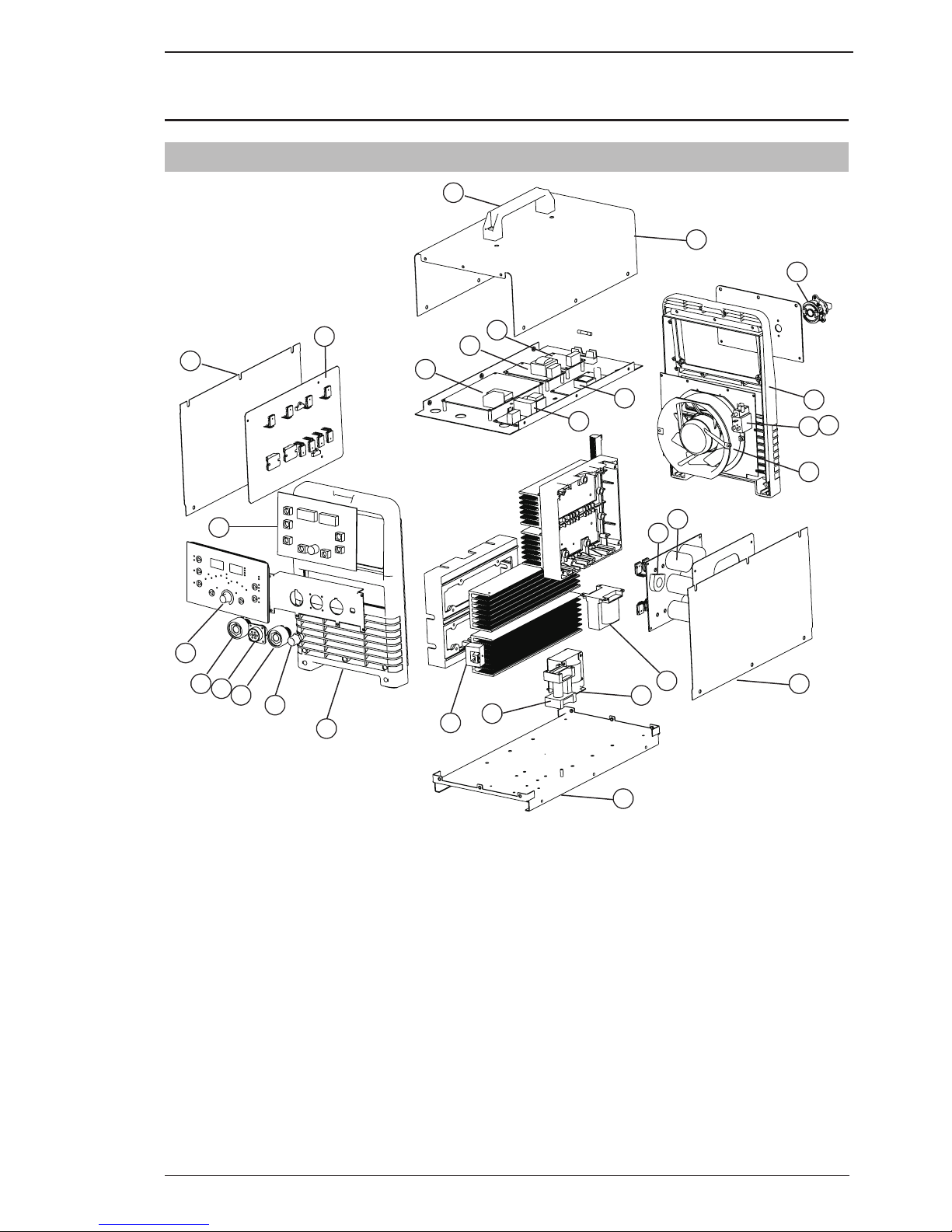
SPARE PARTS 202 AC/DC INVERTER
Manual 0-5239 6-1 KEY SPARE PARTS
SECTION 6:
KEY SPARE PARTS
6.01 Power Source
1
2
3
4
5
6
7
8
10
13
14
16
9
11
A-11408
15
12
12
28
25
22
21
23
28
19
17
18
26
20
24
Figure 6-1
Page 56

202 AC/DC INVERTER SPARE PARTS
KEY SPARE PARTS 6-2 Manual 0-5239
202 AC/DC Spare Parts
Item Part Number Description
1 W7005500 PCB display
2 W7005502 PCB HF
3 W7005503 PCB aux power supply
4 W7005504 PCB primary inverter
5 W7005505 PCB AC output drive
6 W7005506 PCB control
7 W7005507 PCB secondary rectifier
8 W7005508 PCB EMC filter
9 W7005509 Coil coupling HF
10 W7005512 Fan assembly
11
W7003033 Gas solenoid assembly
12
W7005513 Dinse Socket 50mm²
13
W7003036 Control socket 8 pin
14 W7005514 Gas outlet, front panel
15 W7005515 Switch, On/Off
16
W7003076 CT, output
17
W7005511 Transformer 202AC/DC
18
W7005510 Inductor 202AC/DC
19
W7005534 Base Panel
20
W7005531 Front panel
21
W7005532 Rear panel
22
W7005535 Panel, Top Cover
23
W7005605 Gas inlet fitting
24
W7005537 Control knob, (25mm2 OD)
25
W7005536 Handle
26
W7004952 CT, primary
27
W7004930 Shielding gas hose assembly
28
W7005538 Side Panel
Table 6-1
Page 57
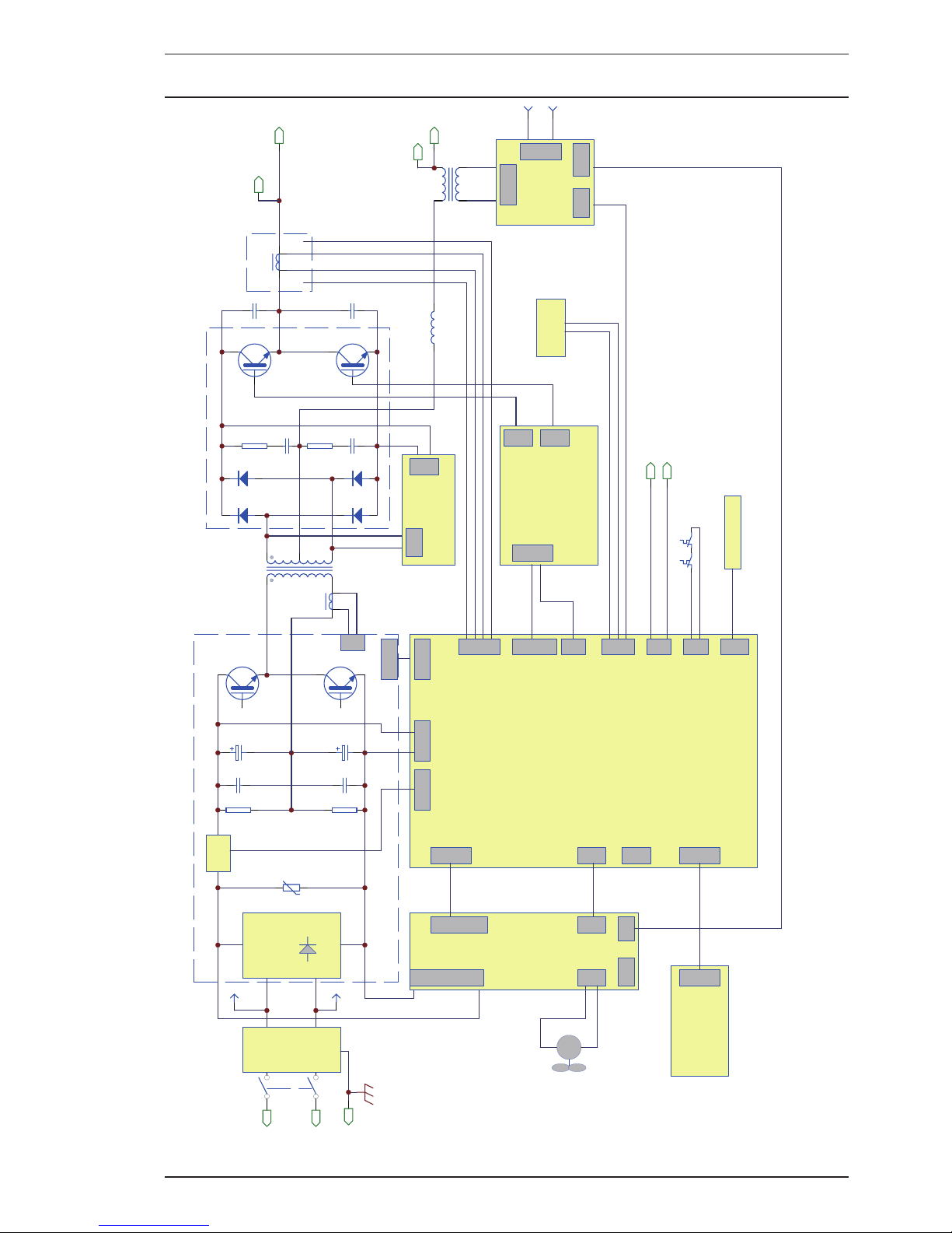
APPENDIX 202 AC/DC INVERTER
Manual 0-5239 A-1 APPENDIX
APPENDIX: CIRCUIT DIAGRAM
Q1
D1
A
N
E
INPUT
RECTIFIER
R1
R1
POSITIVE
NEGATIVE
FAN 24VDC
G1
C3
Q2
G2
T1
R3
C5
D3
NEGATIVE
POSITIVE
HALL EFFECT
CT2
MAIN CONTROL BOARD
WELDING TERMIN
ALS
DC BOARD
SW1
C1
R2
C4
C2
D2
D4
R4
C6
Q3
G3
Q4
G4
C7
C8
L1
T2
SOFT
START
WA
AC
DC
DRIVE
DRIVER
SS
POWER SOU
HF BOARD
HFOUT
HF SOUIN
AC DRIVE BOARD
JBACPOUT
ACOUT
GD1 GD2
QF/HF
DISPLAY BOARD
J2 (10)
JB (10)
DCIN
SOLENOID
POWER SUPPLY BOARD
POWER/FJ
DC-IN
DY2
DY1
8 PIN REMOTE
GUNOT
TH1
TH2
NTCS
WV
WELD POSITIVE
WELD NEGATIVE
WELD POSITIVE
WE
LD NEGATIVE
EMC
FILTER
CT1
OC
MOD
FAN
240VAC
240VAC
0VAC
0VAC
220VAC
A-11227_AB
Page 58

Page 59

LIMITED WARRANTY & WARRANTY SCHEDULE
In accordance with the warranty periods stated below, Victor Technologies guarantees the proposed product
to be free from defects in material or workmanship when operated in accordance with the written instructions
as defined in this operating manual.
Victor Technologies welding products are manufactured for use by commercial and industrial users and trained
personnel with experience in the use and maintenance of electrical welding and cutting equipment.
Victor Technologies will repair or replace, at its discretion, any warranted parts or components that fail due
to defects in material or workmanship within the warranty period. The warranty period begins on the date of
sale to the end user.
Welding Equipment - Limited Warranty Period
Product Period
Thermal Arc 202AC/DC 2 Years
TIG Torch, Electrode Holder & Work Lead 30 Days
MIG Gun Consumables NIL
If warranty is being sought Victor Technologies must be notified in writing within 30 days of the failure and
at such time we will make arrangements to fulfil the warranty claim. Please contact your Victor Technologies
product supplier for the warranty repair procedure.
Victor Technologies warranty will not apply to:
• EquipmentthathasbeenmodiedbyanyotherpartyotherthanVictorTechnologies’sownservicepersonnel or with prior written consent obtained from Victor Technologies Service Department (UK).
• Equipmentthathasbeenusedbeyondthespecicationsestablishedintheoperatingmanual.
• Installationnotinaccordancewiththeinstallation/operatingmanual.
• Anyproductthathas been subjected to abuse, misuse, negligenceor accident, improper care and/or
maintenance including lack of lubrication, maintenance and protection, will be refused warranty.
• Failuretocleanandmaintainthemachineassetforthintheoperating,installationorservicemanual.
Within this operating manual are details regarding the maintenance necessary to ensure trouble free operation.
This manual also offers basic troubleshooting, operational and technical details including application usage.
Using this manual correctly will ensure the quickest time possible for resolving any technical questions, application issues or defects with your Victor Technologies product.
You may also wish to visit our web site www.victortechnologies.com select your product class and then select
literature. Here you will find documentation including:
• Operatormanuals
• Servicemanuals
• Productguides
Alternatively please contact your Victor Technologies distributor and speak with a technical representative.
NOTE
Warranty repairs must be performed by either a Victor Technologies Service Centre, a Victor Technologies
distributor or an Authorised Service Agent approved by the Company.
Page 60

THE AMERICAS
Denton, TX USA
U.S. Customer Care
Ph: 1-800-426-1888 (tollfree)
Fax: 1-800-535-0557 (tollfree)
International Customer Care
Ph: 1-940-381-1212
Fax: 1-940-483-8178
Miami, FL USA
Sales Office, Latin America
Ph: 1-954-727-8371
Fax: 1-954-727-8376
Oakville, Ontario, Canada
Canada Customer Care
Ph: 1-905-827-4515
Fax: 1-800-588-1714 (tollfree)
EUROPE
Chorley, United Kingdom
Customer Care
Ph: +44 1257-261755
Fax: +44 1257-224800
Milan, Italy
Customer Care
Ph: +39 0236546801
Fax: +39 0236546840
ASIA/PACIFIC
Cikarang, Indonesia
Customer Care
Ph: 6221-8990-6095
Fax:
6221-8990-6096
Rawang, Malaysia
Customer Care
Ph: +603 6092-2988
Fax: +603 6092-1085
Melbourne, Australia
Australia Customer Care
Ph: 1300-654-674 (tollfree)
Ph: 61-3-9474-7400
Fax: 61-3-9474-7391
International
Ph: 61-3-9474-7508
Fax: 61-3-9474-7488
Shanghai, China
Sales Office
Ph: +86 21-64072626
Fax: +86 21-64483032
Singapore
Sales Office
Ph: +65 6832-8066
Fax: +65 6763-5812
Form No. 0-5239 (07/9/12) © 2012 Victor Technologies International, Inc. www.victortechnologies.com Printed in China
U.S. Cust omer Care: 80 0- 426-1 88 8 • Canada Custom er Care: 90 5-827-451 5 • Int er national C ustomer Care : 940-381-1 212
I N N O V A T I O N T O S H APE THE W ORL D
™
T ECHNOLOGIE S
™
 Loading...