


!"#$%&'&
Thermal Arc 186 AC/DC
Setup Guide

Thermal Arc 186 AC/DC Complete System Overview
!"#$%&(&
!"#$%&'()*$%*$#'
• '+,%-&./'0-1'234'0(56('7)8%-'!9::/"''
• '+;<'+)-1,'='011%##)->%#?'@4'!$"/%'8>$,'>*$%A-.$%B'1)*$-)/#'''
''CD'1)*$-)/'&)B9/%#'>*1/9B%BE?'2D'F'CG'&E''
• '+8%1)'@HH'0&:'I/%1$-)B%'J)/B%-'8>$,'2D'F'CG'&E'K%.B''
• '+8%1)'@HH'0&:'<-)9*B'(/.&:'8>$,'2H'F'CD'&E'K%.B''
• 'L>1$)-'0-A)*'M/)8'<.9A%'='2@NO'F'CDN3'&E'J)#%''
• 'P'F'C@NQO'&E'7)8%-'()-B'.*B'RIS0'4TOH7'@DH'0('7/9A''
• 'U:%-.$)-#'S.*9./'='(6''
• '<%*%-./'79-:)#%'!V1W'I/%1$-)B%#'CI4H2DE''
• '!,)9/B%-'!$-.:''
XY;(Z'!7I(;M;(0+;UR!''
''
7[U(I!!I!'\ ''
JM'+;<'C<+0]E'K>F'+;<'C<+0]E'
!+;(Z'C!S0]E''
''
[0+I6'UY+7Y+' ''
())*&+&',-&.&()/&0123&435"%&
',)*&+&'67(-&.&(8/&0123&435"%&
'8)*&+&'9-&.&:8/&0123&535"%&&
&&
S0^N'U7IR'(;[(Y;+'LUK+0<I'
6)7:-&04&+&8)&-*4&&
&&
0S7I[0<I'[0R<I' ''
');())&*& &&
&
]I;<J+' ''
<,7<&"=>&?((&@AB ''

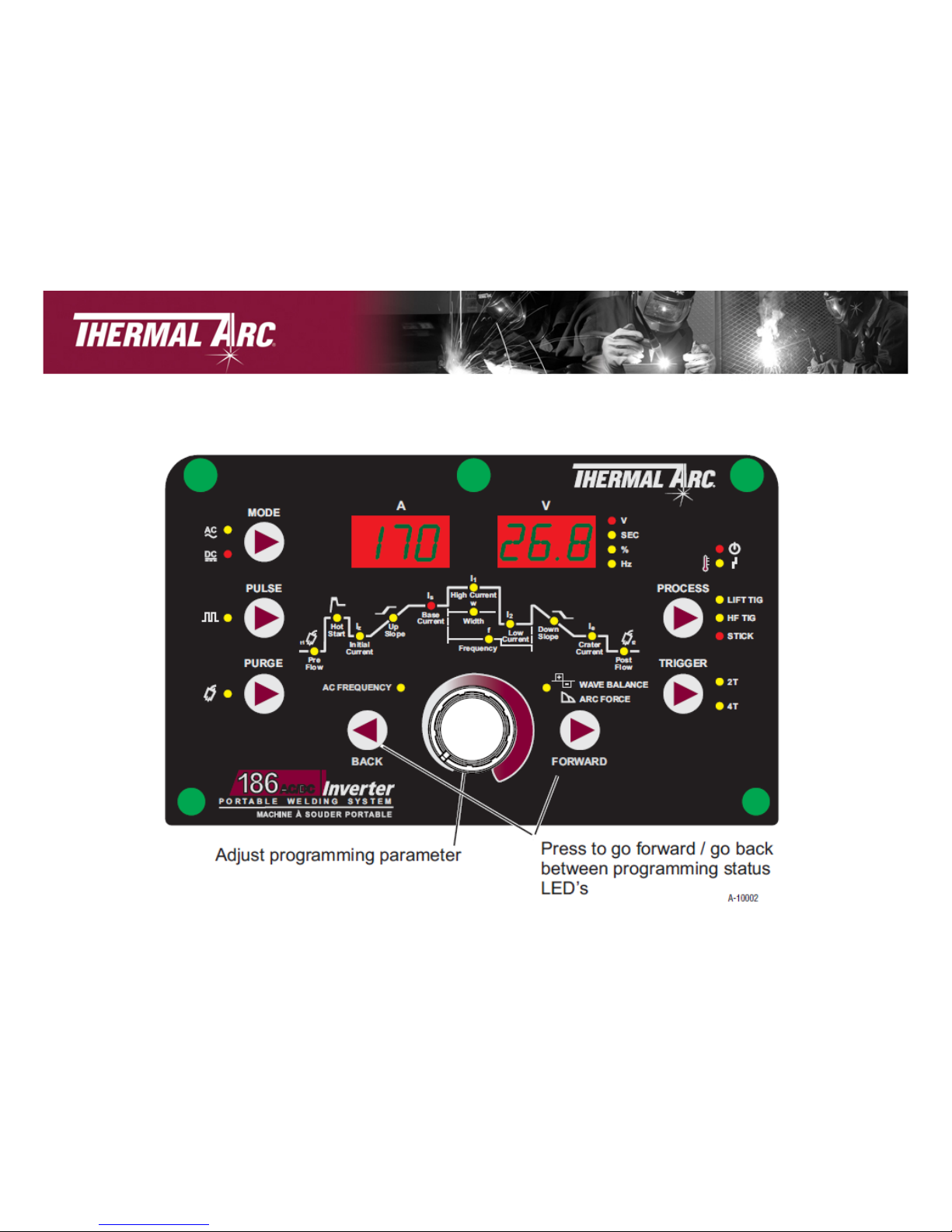
186 AC/DC Front Panel Overview
!"#$%&:&
Digital Meters-
Displays both the pre-set and
actual output current and
voltage of the power source.
Also used to display parameters
in programming mode.
AC/DC
Mode,
Pulse and
Purge
Buttons
Process
Selection
Button -
Three modes
are available,
GTAW (LIFT
TIG), GTAW (HF
TIG) & SMAW
(Stick) modes.
Trigger
Control
Button
Multi Function
Control Knob
Programming Parameter
Indicator Lights

TIG Torch and Control Modules Overview&
!"#$%&<&
TIG Torch Contents:
• 26 TIG Torch with Long Back Cap
• 12.5 ft lead length
• 10. 5 in gas hose length
• 9.5 in control lead with 8 pin plug and Rigid Head.
• Remote Control Cartridge, Potentiometer with integrated on/off
switch (installed).
0C>$C>$C&
!$C>$C&
>$C>$C&
Additional switches/controls are interchangeable with the
installed control in the TIG torch.
Control module
with push button
on/off switch only.
Control module with
push button on/off
switch with roller
potentiometer.
Control module
with roller
potentiometer and
integrated on/off
switch.
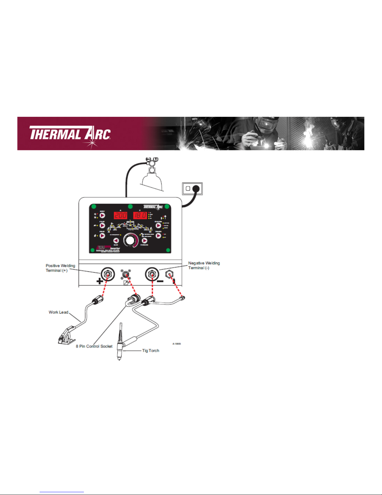
TIG Setup
!"#$%&8&
1. Connect the TIG Torch to the negative
welding terminal (-). Welding current
flows from the power source is
heavy duty bayonet type terminals. It is
essential, however, that the male plug is
inserted and turned securely
to achieve a sound electrical connection.
2. Connect the work lead to the positive
welding terminal (+). Welding current
flows from the Power Source is
heavy duty bayonet type terminals. It is
essential, however, that the male plug is
inserted and turned securely
to achieve a sound electrical connection.
3. Fit the welding grade shielding gas
regulator/flowmeter to the shielding gas
cylinder, then connect the shielding gas
hose from the regulator/flow meter outlet
gas INLET on the rear of the 186 AC/DC
Power Source. Connect the gas hose
from the TIG torch to the gas OUTLET
on the front of the
186 AC/DC Power Source.

Lift TIG and HF TIG Programming Modes
(Corresponding diagram on following page)
1. Turn ON the ON/OFF switch located on the rear panel of the
power source.
2. Press the PROCESS button to select LIFT TIG or HF TIG mode.
3. Press the MODE switch to toggle between AC and DC welding
output.
4. The Programming LED's are always active. Press FORWARD or
BACK to cycle through available programming functions.
5. Use the Multi Function Control to adjust the parameter
selected.
!"#$%&9&

Lift TIG and HF TIG Programming Modes
!"#$%&6&

Lift TIG and HF TIG Programming Modes Cont.
!"#$%&,&
Range:
Range:
Range:
Range:
Range:

D#E&FGH&IJ$&KL&FGH&MNOANIPP#JA&QO$%>&4OJ27&
!"#$%&R&
Range:
Range:
Range:
Range:
Range:

Lift TIG and HF TIG Programming Modes Cont.
!"#$%&')&
Range:
Range:

D#E&FGH&IJ$&KL&FGH&MNOANIPP#JA&QO$%>&4OJ27&
!"#$%&''&
• &S*T&U*D*V4T&#>&1>%$&CON&I"1P#J1P&W%"$#JA&#J&*4&KL&FGH&ON&*4&DGLF&FGH&PO$%&
• &G2&#>&1>%$&2O&>%2&2X%&NIYO&OC&Z%J%2NIYOJ&2O&5"%IJ#JA&I5YOJ&CON&2X%&*4&FGH&W%"$#JA&
IN57&
• &QI[#P1P&W%"$&Z%J%2NIYOJ&#>&I5X#%\%$&WX%J&2X%&S*T&U*D*V4T&#>&>%2&2O&')/7&&
• &QI[#P1P&5"%IJ#JA&OC&X%I\#"3&O[#$#]%$&I"1P#J1P&ON&PIAJ%>#1P&I""O3>&#>&I5X#%\%$&
WX%J&2X%&S*T&U*D*V4T&#>&>%2&2O&98/7&

STICK Setup
!"#$%&'(&
1. Connect the Electrode Holder lead
to the positive welding terminal (+). If
in doubt, consult the electrode
manufacturer. Welding current flows
from the Power Source is heavy duty
bayonet type terminals. It is essential,
however, that the male plug is
inserted and turned securely to
achieve a sound electrical connection.
2. Connect the work lead to the
negative welding terminal (-). If in
doubt, consult the electrode
manufacturer. Welding current flows
from the power source is heavy duty
bayonet type terminals. It is essential,
however, that the male plug is
inserted and turned securely to
achieve a sound electrical connection.
3. Select STICK mode with the
process selection control7&

!FG4^&MNOANIPP#JA&QO$%>&
&?4ONN%>ZOJ$#JA&$#IANIP&OJ&CO""OW#JA&ZIA%B&
'7 F1NJ&_V&2X%&_V+_LL&>W#25X&"O5I2%$&OJ&2X%&N%IN&ZIJ%"&OC&
2X%&ZOW%N&>O1N5%7&
(7 MN%>>&2X%&M`_4T!!&=1aOJ&2O&>%"%52&!FG4^&PO$%7&
:7 MN%>>&2X%&Q_0T&>W#25X&2O&2OAA"%&=%2W%%J&*4&IJ$&04&
W%"$#JA&O12Z127&
<7 FX%&MNOANIPP#JA&DT0b>&IN%&I"WI3>&I5Y%7&MN%>>&L_`S*`0&
ON&U*4^&2O&535"%&2XNO1AX&II#"I="%&ZNOANIPP#JA&C1J5YOJ>7&
87 c>%&2X%&Q1"Y&L1J5YOJ&4OJ2NO"&2O&I$d1>2&2X%&MINIP%2%N&
>%"%52%$7&
97 SX#"%&W%"$#JA&2X%&Q1"Y&L1J5YOJ&4OJ2NO"&$#N%52"3&5OJ2NO">&
2X%&U*!T&4c``TVF&
!"#$%&':&
!FG4^&MNOANIPP#JA&QO$%>&
&
!"#$%&'<&
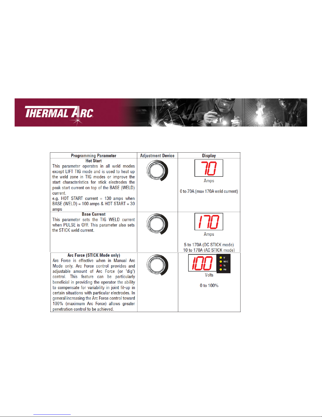
STICK Programming Modes Cont.&
&
!"#$%&'8&
Range:
Range:
Range:
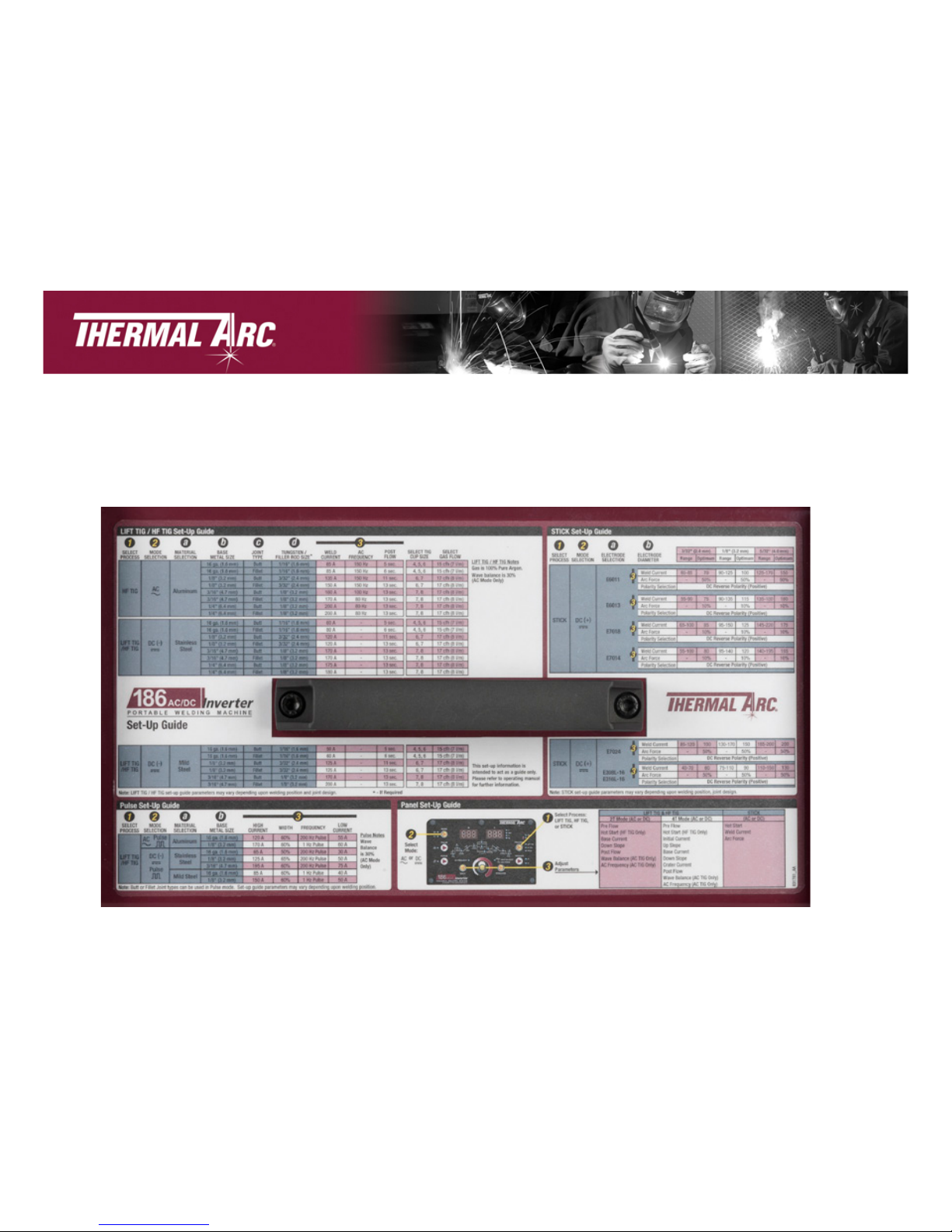
Setup Chart
!"#$%&'9&
Refer to Setup Chart on top of machine for weld parameters and
guidelines
 Loading...