

Thermaflow TSL9/140U, TSL9/170U, TSL12/140U, TSL12/170U Instructions For Use Installation And Servicing

ELECTRIC SLIMLINE COMBINATION BOILER
(Patent Pending, Design Right Protected.)
TSL9/140U & TSL9/170U
TSL12/140U & TSL12/170U
SOLAR COMPATIBLE
This product is suitable for connection to ~230-240V, 50Hz
INSTRUCTIONS FOR USE, INSTALLATION AND
SERVICING
TO BE LEFT WITH THE USER
The instructions consist of three parts; User, Installation and Servicing instructions, which include the guarantee
registration card.
The instructions are an integral part of the appliance and must, to comply with the current issue of the building, electrical
regulations and water by-laws, be handed to the user on completion of the installation.
GUARANTEE REGISTRATION
Thank you for installing a new Thermal Innovations product in your home.
Thermal innovations appliances, are manufactured to the very highest standards so we are pleased to offer our
customers, a comprehensive first year parts & Labour guarantee and a second year parts guarantee.
In the instruction envelope is to be found your guarantee registration card, which must be completed and returned to
Thermal Innovations (UK) Ltd or register your Thermal Innovations (UK) Ltd appliance for 1st year guarantee protection by
calling the below number.
Our guarantee gives you peace of mind valuable protection against breakdown by covering the cost of-
• All replacement parts
• All labour charges
• All call-out charges
THERMAL INNOVATIONS (UK) LTD
31-39 Napier Court, Cumbernauld, Glasgow, G68 0LG
Customer services
Tel +44 (0) 870 850 5207
Fax +44 (0) 870 850 5208
Web www.thermaflowheating.co.uk
Issue Number: 1a Issue date: July 2008
Copyright Notice
This document contains proprietary information protected by copyright, and this Manual and documentation are copyrighted. All rights are reserved. No part
of this document may be photocopied or reproduced by mechanical, electronic, or other means in any form without permission from Thermal Innovations
(UK) Ltd.
© Copyright Thermal Innovations (UK) Ltd 2006-09 -All rights reserved.

THERMAL INNOVATIONS (UK) LTD | THERMAFLOW® ELECTRIC COMBINATION BOILER | Tel: 0870 850 5207
Contents
0.1
..................................................................................4 Instructions general
......................................................................................5 Draining & Filling
0.2
0.3
......................................................................5 Manual Handling Guidance
0.4
....................................................................5 TESTING & CERTIFICATION
0.5
................................................................................5 THE UNIT LOCATION
Part1 - INSTRUCTIONS FOR USE............................................................................7
1.1 .........................................................................................7 INTRODUCTION
.............................................................7 Domestic hot water temperature
1.2
.................................................................................7 To turn the boiler off
1.3
1.4
......................................................................7 Maintenance and servicing
1.5
.................................................................................................7 Clearances
1.6
....................................................................................8 Draining and filling
....................................................................................8 Replacement parts
1.7
1.8
........................................................................................9 GENERAL DATA
Part 2 - INSTALLATION ..........................................................................................11
2.1.1 Sheet metal parts .......................................................................................11
2.1.2 Statutory requirements..............................................................................11
2.1.3 DATA 11
2.1.4 ELECTRICAL SUPPLY...............................................................................11
2.1.5 Electrical supply ........................................................................................11
2.1.6 Heating system controls ...........................................................................12
2.2.1 Boiler Position............................................................................................12
2.2.2 Boilers in a compartment..........................................................................12
2.2.3 Clearances..................................................................................................14
2.3.1 General notes .............................................................................................14
2.3.2 Safety valve ................................................................................................14
2.3.3 Pressure Gauge .........................................................................................14
2.3.4 Pump 14
2.3.5 Expansion vessel.......................................................................................14
2.3.6 By- pass ......................................................................................................14
2.3.7 Filling sealed systems...............................................................................14
2.3.8 Corrosion inhibitor.....................................................................................14
2.3.9 Draining ......................................................................................................14
2.4. Domestic hot water system.........................................................................15
2.4.1 General 15
2.4.2 Water pressure...........................................................................................15
2.4.3 HOT WATER FLOW RATE .........................................................................15
2.4.4 Hard water areas ........................................................................................15
2.5. Installation, PREPARATION [water connections] .....................................15
2.5.1 Water connections..................................................................................15
2.5.2 Safety valve discharge ...........................................................................15
2.6 Electrical Installation Requirements ...........................................................16
2.6.1 SUPPLY .................................................................................................16
2.6.2 18
2.6.3 External Controls....................................................................................19
Electrical Connections.....................................................................................20
2.6.4 Supply cable connection [24 HR Supply] ...............................................20
2.6.5 Heating system controls.........................................................................20
2.6.6 Electrical Test.........................................................................................20
2.6.7 Supply cable connection [Interrupted off peak supply]...........................21
2.6.8 Electrical Test.........................................................................................21
Electricity tariffs ...............................................................................................21
2.7 Commissioning .............................................................................................21
2.7.1 Filling domestic water circuit...................................................................21
2.7.2 Filling the heating system.......................................................................21
2.7.3 Domestic hot water flow rate..................................................................22
2.7.4 Temperature settings..............................................................................22
2

THERMAL INNOVATIONS (UK) LTD | THERMAFLOW® ELECTRIC COMBINATION BOILER | Tel: 0870 850 5207
2.7.5 Heating system commissioning..............................................................22
2.7.6 Completion .............................................................................................23
Instruct the user...............................................................................................23
Part 3 - SERVICING .................................................................................................24
3.1. Fault Finding.................................................................................................24
Fault: No domestic hot water or central heating..............................................25
Fault: No central heating, but hot water at taps...............................................26
Fault: CENTRAL HEATING BUT No hot water at taps ...................................27
3.2 ISOLATION ...............................................................................................28
Checking the pressure in the expansion vessel..............................................28
Checking the inline strainer............................................................................. 28
Checking the hot water blending valve............................................................28
Checking the concentration of corrosion inhibitor............................................29
Preventing pump seizure in summer...............................................................29
Checking correct operation of electrical components......................................29
Low pressure switch........................................................................................29
Control and high limit thermostats...................................................................29
Checking the elements....................................................................................29
Checking circuit breakers................................................................................30
Checking the contactor....................................................................................30
Check the operation of the AQUA STAT.........................................................30
Appendix I – Solar Connection..............................................................................31
A1.1 Solar Pipe work Schematic.....................................................................31
A1.2 Solar Wiring Schematic...........................................................................32
IMPORTANT PRE-INSTALLATION NOTES
• Power supply and wiring
The power supply to the premises must meet the minimum requirements of the unit being installed, with
special attention given to the supply current, cable size and MCB recommendation. The supply voltage to the
appliance must never drop below 207 Volts.
Important
The electrical supply requirements:-
The 9 KW and 12 KW boilers meet the requirements of EN 61000-3.3
The 9 KW and 12 KW boilers must be installed in premises having a service supply of ≥ 100A
per phase.
The 12 KW boiler must be installed in premises having a system impedance of not more than 0.1939 + J
0.1939Ω
3
THERMAL INNOVATIONS (UK) LTD | THERMAFLOW® ELECTRIC COMBINATION BOILER | Tel: 0870 850 5207
0.1 Instructions general
A pressure reducing valve must be fitted to the cold water inlet if the incoming water pressure
exceeds 400 KPA (4.0 Bar).
The primary operating pressure initial charge is 120 KPA (1.2Bar) this will increase to around 200
KPA (2.0Bar) when the system has reached maximum temperature and will depend on system
volume.
The primary expansion vessel pre-charge pressure is 150 KPA (1.5 Bar) and has volume of 25 and
35 litres depending on the model of boiler.
The secondary expansion vessel pre-charge pressure is 350 KPA (1.0 Bar) and has a volume of
1litre.
The primary pressure relief valve is set to 300 KPA (3.0 Bar).
Primary storage
TSL9/140U & TSL12/140U TSL9/170U & TSL12/170U
140 litres 170 Litres
Thermaflow Model Number
capacity
Weight when
50KG 56KG
Empty
Weight when Full 190KG 226KG
WARNING: BEFORE OBTAINING ACCESS TO TERMINALS, ALL SUPPLY CIRCUITS
MUST BE DISCONNECTED.
The TSL9/14OU, TSL9/170U all have 3 heating elements fitted. Size 8” in length and are
manufactured of incaloy EN60335.2.73.
The rated power input of the appliance is ~230- 240V, 50Hz, 8,250-9,000w
The TSL12/140U, TSL12/170U all have 4 heating elements fitted. Size 8” in length and are
manufactured of Incaloy EN60335.2.73.
The rated power input of the appliance is ~230-240V, 50Hz, 11,000-12,000w
The elements fitted to the Thermaflow should NOT be replaced with elements which have no
thermal cut outs
It is recommended that the Thermaflow has a safety and maintenance check on an annual
basis.
A pressure reducing valve must be fitted to the cold water inlet of the appliance if the
incoming pressure exceeds 400kPA (4 Bar).
The position of the Tundish (IF REQUIRED) shall be visible to the occupants and shall be
positioned away from any electrical devices.
The position of discharge pipes, (Tundish), drain valves and motorised valves etc, must be
positioned away from electrical components.
The water may drip from the discharge pipe of the pressure-relief device and must be left
open to the atmosphere.
The pressure relief device must be operated regularly to remove lime deposits and to verify
that it is not blocked.
The discharge pipe connected to the pressure-relief device must be installed in a
continuously downward direction and in a frost free environment.
(Additional Information given in G3 of the building regulations for discharge pipes)
.
4

THERMAL INNOVATIONS (UK) LTD | THERMAFLOW® ELECTRIC COMBINATION BOILER | Tel: 0870 850 5207
0.2 Draining & Filling
CAUTION: THE THERMAFLOW BOILER WORKS IN A PRESSURISED SYSTEM WHICH
MUST ONLY BE DRAINED, REFILLED AND PRESSURISED BY A COMPETENT PERSON.
There is one drain tap fitted to the Thermaflow boiler to drain the primary circuit within the boiler the
drain tap is located at the bottom of the appliance. Further drain taps should be fitted into the pipework at the lowest point of the potable water circuit and the heating circuit and should terminate
outside the dwelling in a suitable position.
0.3 Manual Handling Guidance
During the appliance installation it will be necessary to employ caution and assistance whilst
lifting as the appliance exceeds the recommended weight for a one man lift.
DO NOT LIFT THE APPLIANCE BY ATTACHED PIPE-WORK OR COMPONENTS
In certain situations it may be required to use a mechanical handling aid.
Take care to avoid trip hazards, slippery or wet surfaces.
IMPORTANT INFORMATION
0.4 TESTING & CERTIFICATION
The boiler is tested and certified for safety and performance. It is therefore important that no
alteration is made to the boiler, without permission, in writing, from Thermal Innovations (UK) Ltd.
Any alteration not approved by Thermal Innovations (UK) Ltd, could invalidate the certification,
boiler warranty and may also infringe the current issue of the statutory requirements, see section
2.1.2
The unit should be stored in a dry environment and should be handled with care to prevent attached
components being damaged or connections becoming loose.
leaks after installation
.
All connections should be checked for
0.5 THE UNIT LOCATION
The unit should be preferably located in a cupboard with a minimum dimension of;
L 650 mm x B 550 mm H 2.1m for the
L 650 mm x B 550 mm X H2.4M for
TSL9/14OU & TSL12/140U.
TSL9/170U & TSL12/170U
The floor to which the unit is placed upon should be capable of withstanding a load of:
190KG for the
TSL9/14OU & TSL12/140U
226KG for the TSL9/170U & TSL12/170U
The unit should be positioned in a manner that allows access to all components for future
maintenance. If located in a cupboard the unit should be positioned with all components
facing the entrance to allow elements to be replaced if required or any of the other
components.
5

THERMAL INNOVATIONS (UK) LTD | THERMAFLOW® ELECTRIC COMBINATION BOILER | Tel: 0870 850 5207
There are five water connections to be made when installing the Thermaflow, they are as follows:
1) Flow and return connections to the heating system are 22mm compression.
2) Cold water inlet-22mm compression.
3) Hot water outlet -22mm compression.
4) Pressure relief valve- 15mm compression.
5) The pressure relief valve connection should be used for no other purpose.
6

THERMAL INNOVATIONS (UK) LTD | THERMAFLOW® ELECTRIC COMBINATION BOILER | Tel: 0870 850 5207
PART1 - INSTRUCTIONS FOR USE
1.1 INTRODUCTION
This appliance is not intended for use by persons (including children) with reduced physical,
sensory or mental capabilities, or lack of experience and knowledge, unless they have been
given supervision or instruction concerning use of the appliance by a person responsible for
their safety.
Children should be supervised to ensure they do not play with the appliance.
Please read these Instructions and follow them carefully for the safe and economical use of your
combination boiler.
This boiler must have been installed by a competent person in accordance with the current rules in
force in the countries of destination at the time of installation.
The boiler is automatic in operation once the external controls are set e.g. time clock or
programmable room thermostat.
IMPORTANT NOTICE
1.2 Domestic hot water temperature
Hot water is user adjustable by turning the control knob on the thermostatic mixing valve fitted on
the hot water outlet at the top left of the boiler. It has a maximum anti-scald cut off at 63oC.
The combination boiler is able to provide room heating as part of an under-floor or central heating
system and domestic hot water direct from the cold water supply, without the need for secondary
storage.
1.3 To turn the boiler off
To turn the boiler off, isolate the boiler from both the electrical supplies i.e. the 24hr supply and the
interrupted supply, both isolating switches should be positioned next to the boiler.
1.4 Maintenance and servicing
To ensure the continued efficient and safe operation of the appliance it is recommended that it is
checked and serviced as necessary at regular intervals. The frequency of servicing will depend
upon the particular installation conditions and usage, but in general once a year should be enough.
Servicing & maintenance should be carried out by a competent person in accordance with the rules
in force in the countries of destination.
To obtain service please call your installer or Thermal Innovations (UK) Ltd, using the telephone
number on the appliance or at the front of this manual.
Please be advised that the Thermal Innovations (UK) Ltd log book should be completed by the
installation engineer on completion of commission and servicing.
1.5 Clearances
The boiler requires a clearance in front and at the sides for safety, servicing and maintenance
access, see diagram 2.2.3 for the requirements.
7

THERMAL INNOVATIONS (UK) LTD | THERMAFLOW® ELECTRIC COMBINATION BOILER | Tel: 0870 850 5207
1.6 Draining and filling
Caution this boiler works in a pressurised system which must only be drained, refilled and
pressurised by a
person competent to do so.
Note: if the pressure gauge indicates a loss of pressure that is less than 60 KPA (0.6 Bar)
YOU MUST CONTACT YOUR
unless you have been instructed by your installer on how to re-pressurise the system correctly.
INSTALLER,
1.7 Replacement parts
If replacements parts are required, contact your Installer, Service Company or Thermal Innovations
(UK) Ltd. Please quote the name and model of your appliance. (Ref. Spare Parts List - section
1.8.1).
8

THERMAL INNOVATIONS (UK) LTD | THERMAFLOW® ELECTRIC COMBINATION BOILER | Tel: 0870 850 5207
1.8 GENERAL DATA
Diagram 1.8.1
1 Enclosure for Low Pressure
cut-out switch & Master nonreset-able over-temperature
thermostat
2 Safety Relief Valve 300kPA
(3bar)
3 Enclosure for Contactor and
Circuit Breakers
4 22mm Compression bends
DZR
5 Pipe work
6 Filling Loop Assembly
6a Pressure gauge
7 Circulating Pump Complete
with Isolating Valves.
Central Heating Pump
8 Heating Elements
9 Aqua Thermostat
10 10-1 Enclosure for incoming
live supply, central heating
pump & Aqua stat
11 Heat Resistant Flex
12 0.5 Litre Potable expansion
vessel
13 Thermostatic Blending Valve
13b HW outlet
15 Automatic Air Eliminator
15b- connection for primary
expansion vessel ( Blank off if
connecting to CH Return
16 Stainless Steel Primary Store
17 17-1 Single check valve –
cold water inlet
17-2 Single check valve – CH
flow
17-3 Y-pattern strainer (cold
water inlet)
18 18-1 Drain point (Primary )
20 Primary Expansion vessel –
connect into CH return at
boiler or at 15B
Unit Design (Protected by Design Rights)
9

THERMAL INNOVATIONS (UK) LTD | THERMAFLOW® ELECTRIC COMBINATION BOILER | Tel: 0870 850 5207
TABLE 1.8.1 [DATA]
Lift Weight 50KG 56KG Total Weight 60KG 66KG Weight Full 190KG 226KG Heating Flow Return 22mm Compression Domestic Cold Inlet 22mm Compression Domestic Hot Outlet 22mm Compression Safety Valve PRESET 300 KPA (3.0 Bar) Safety Valve Discharge 15mm Compression Water Content Primary 140 Litres 170 Litres Water Content Domestic 4.5 Litres / 1.0 Gallons Primary Expansion Vessel 25 Litres / 5.5 Gallons Heating Cold Fill Pressure Min/Max 90 KPA (0.9 Bar) minimum / 120 KPA (1.2 Bar) maximum D.H.W Working Pressure 20 – 400 KPA (0.2-4.0 Bar)
TSL9/12/140 TSL9/12/170
Max. Heating system Content (Excluding unit
140Litres 160Litres
volume)
Electrical Mains Supply ~230-240V, 50Hz
Electrical Rating (Interrupted) & Supply Current TH9/ 8,250-9,000w- 40amp
TH12/ 11, 000-12,000w – 52 amp
MCB Rating (amp) 9Kw (40amp) 12Kw (52amp)
Electrical Rating (24Hr 95w, Fused 3amp
10

THERMAL INNOVATIONS (UK) LTD | THERMAFLOW® ELECTRIC COMBINATION BOILER | Tel: 0870 850 5207
PART 2 - INSTALLATION
2.1.1 Sheet metal parts
Warning: when installing or servicing this boiler care should be taken when handling the edges of
metal parts to avoid any possibility of personal injury.
2.1.2 Statutory requirements
The installation of this boiler must be carried out by a competent person in accordance with the
current rules in force in the countries of destination at the time of installation, and in accordance with
the relevant requirements of the current issue of:
The Building Regulations
The Local Water Company bye-laws
The Building Standards Regulations (Scotland)
The Health and Safety at Work Act
Manufacturers instructions, supplied
Manufacturer’s instructions must not be taken as overriding statutory requirements.
2.1.3 DATA
The data label is on the front case of the boiler.
2.1.4 ELECTRICAL SUPPLY
Power supply and wiring
•
The power supply to the premises must meet the minimum requirements of the unit being installed, with
special attention given to the supply current, cable size and MCB recommendation. The supply voltage to the
appliance must never drop below 207 Volts.
Important
The electrical supply requirements:The 9 KW and 12 KW boilers meet the requirements of EN 61000-3.3
The 9 KW and 12 KW boilers must be installed in premises having a service supply of ≥ 100A
per phase.
The 12 KW boiler must be installed in premises having a system impedance of not more than 0.1939 + J
0.1939Ω
WARNING: This boiler must be earthed
WARNING: Means for disconnection must be incorporated in the fixed wiring in
accordance with the wiring rules
WARNING: Electrical work must be carried out by a person competent to do so
All system components shall be of an approved type.
The electrical installation shall be in accordance with the current rules in force in the countries of
destination at the time of installation.
2.1.5 Electrical supply
Means of disconnection of the electrical supply to the boiler must be incorporated in the
fixed wiring in accordance with the wiring rules.
11

THERMAL INNOVATIONS (UK) LTD | THERMAFLOW® ELECTRIC COMBINATION BOILER | Tel: 0870 850 5207
Two isolators are required, one for the 24hr supply, and the other for the interrupted supply
(off peak if available)
Means of disconnection of the 24hr supply should be by a double pole switched fused spur box
(fuse rating 3 amp), having a minimum contact separation of 3mm in each pole. The fused spur box
should be readily accessible and adjacent to the appliance. It should be identified as to its use.
Means of disconnection should not be fitted in a room containing a fixed bath or shower. The 24hr
mains supply cable and other cables for external controls must be heat resistant and flexible PVC
type of at least 0.75mm2 (24/ 0.20mm)
Means of disconnection of the interrupted supply (off peak) should be by a double pole switched
(60amp isolator with a 40 amp MCB Type C for the TH9/ model) and a switched (100 amp isolator
with a 50 or 63 amp MCB Type C for the TH12/ model), having a minimum contact separation of
3mm in each pole. The switched isolator should be readily accessible and adjacent to the appliance.
It should be identified as to its use.
Means of disconnection should be readily accessible and adjacent to the appliance. It should
be identified as to its use.
The interrupted mains supply cable must have a cross sectional area of at least (10mm² for
the TSL9/ model) and (16mm² for the TSL12/ model). The mains supply cable from the
isolator to the boiler should be preferably encased by flexible conduit.
2.1.6 Heating system controls
The heating system should have installed: A timer and room thermostat or a programmable room
thermostat controlling the central heating system.
Thermostatic radiator valves should be installed in addition to the room thermostat for better
economy and energy saving.
2.2.1 Boiler Position
The boiler must be installed in accordance with the rules in force in the countries of destination. This
boiler is not suitable for fitting outside.
Any electrical switch must be positioned so that it cannot be touched by a person using the bath or
shower.
The boiler must be positioned on a level base or floor which is sufficiently robust to take its weight,
(Refer to table 1, “Data”)
If the location of the boiler or any part of the system is subject to severe cold weather conditions, it
is recommended that a frost thermostat is fitted. Any part of the system that may be vulnerable to
freezing must be protected.
2.2.2 Boilers in a compartment
Where the installation of the boiler will be in an unusual position, the current issue of BS 6798 gives
detailed guidance on these requirements.
An existing cupboard or compartment modified for the purpose may be used, providing minimum
clearances are maintained. Details of essential requirements for cupboards or compartment design
are given in the current issue of BS6798.
12

THERMAL INNOVATIONS (UK) LTD | THERMAFLOW® ELECTRIC COMBINATION BOILER | Tel: 0870 850 5207
The doorway opening should be of sufficient size to allow for easy removal of the boiler.
Where the boiler is fitted in a cupboard or compartment permanent ventilation is not required.
Compartment ventilation is required to dissipate heat from any external heating circuit pipe-work, to
prevent overheating of the electrical components and wiring.
Any existing compartment air vents must not be removed or blocked off.
13
THERMAL INNOVATIONS (UK) LTD | THERMAFLOW® ELECTRIC COMBINATION BOILER | Tel: 0870 850 5207
Diagram 2.2.3 - Clearances
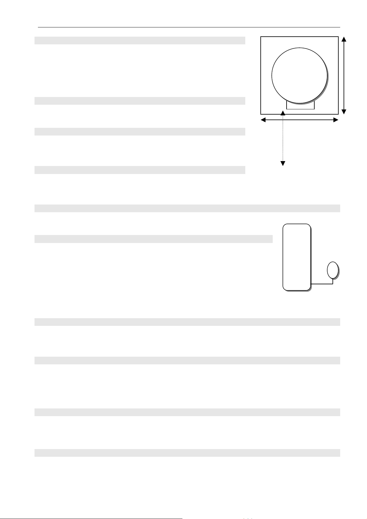
2.2.3 Clearances
The boiler should be positioned so that at least the minimum
operational and servicing clearances are provided, see diagram
2.2.3 additional clearances may be required around the boiler for
installation. A clearance of 600mm is required at the front of the
boiler for maintenance and installation.
2.3.1 General notes
The boiler is intended for use in a sealed system only.
2.3.2 Safety valve
The safety relief valve is an integral part of the boiler. It cannot
be adjusted but has a manual test device.
2.3.3 Pressure Gauge
A pressure gauge is incorporated into the boiler to indicate the system pressure.
The gauge has a cold fill set pointer.
Thermaflow
Unit
front
500mm
600mm
600mm
2.3.4 Pump
The circulation pump is integral with the boiler.
Diagram 2.3.5
2.3.5 Expansion vessel
The TSL9/140U & TSL12/140U, TSL12/170 & TSL12/170U are all supplied
with an expansion vessel with a capacity of 25 litres. If the system water
content exceeds the maximum quoted in
table 1, [Data] an additional vessel
Expansion
Vessel
should be connected into the system as close as possible to the central
heating return connection of the boiler. Ref. Di
The charge pressure shall not be less than the static head at the point of
agram 2.3.5
Thermaflow ®
connection, which is the height of the top point of the system above the expansion vessel.
2.3.6 By- pass
An automatic by- pass valve should be incorporated in the system for maximum system
efficiency. (A By-Pass MUST be fitted on all models).
2.3.7 Filling sealed systems
The boiler has a filling loop incorporated within it, and pressure gauge to register the fill pressure.
There must be no permanent connection to the mains water supply; even though a non return valve
is supplied.
Disconnect filling loop and seal both valves with suitable caps.
2.3.8 Corrosion inhibitor
The maintenance of sufficient concentration of corrosion inhibitor in your Thermaflow system is vital
to prevent corrosion. We would recommend Sentinel X100, or equivalent. Dose appropriately
according to the size of the Thermaflow and central heating system volume combined.
2.3.9 Draining
A draining tap must be provided at the lowest points of the system, which will allow the
entire system to be drained. The boiler has one drain tap fitted to it for the primary circuit.
14

THERMAL INNOVATIONS (UK) LTD | THERMAFLOW® ELECTRIC COMBINATION BOILER | Tel: 0870 850 5207
2.4. Domestic hot water system
2.4.1 General
The domestic hot water service must be in accordance with the rules in force in the countries of
destination.
2.4.2 Water pressure
For the minimum and maximum, working pressures of the domestic hot water circuit of the boiler
refer to
(“data” table 1).
If the cold water inlet pressure exceeds 400 KPA (4 Bar) a pressure reducing valve must be
fitted to the inlet to the boiler.
2.4.3 HOT WATER FLOW RATE
The boiler is capable of flow rates of 15-20 litres per/min @ 40ºC ∆t (depending on model). Hot
water flow rate and pressure will be determined by the volume and pressure of the incoming cold
water supply.
2.4.4 Hard water areas
In areas where the water is “Hard” more than 200 mg / Litre, it is recommended that a proprietary
scale reducer or water softner is fitted in the cold water supply to the boiler. Consult the local water
authority for additional advice.
A double check valve assembly must be fitted upstream of the scale reducer/water softner, for the
relative position of the scale reducer/water softner and pressure reducing valve, if required, refer to
the manufacturers instructions.
2.5. Installation, PREPARATION [water connections]
2.5.1 Water connections
See General Data Diagram 1.8.1 & table 1.8.1 for pipe work connections
It is recommended to flush out the domestic water and heating system before connecting to the boiler.
While making the connections, do not subject any of the connections to heat as you may
damage the seals.
2.5.2 Safety valve discharge
It must not discharge above an entrance or window or any type of public access.
The position of the tundish shall be visible to the occupants and shall be positioned away
from any electrical devices.
The position of discharge pipes, tundish, drain valves and motorised valves etc. must be
positioned away from electrical components.
The water may drip from the discharge pipe of the pressure-relief device and must be left
open to the atmosphere.
The pressure relief device must be operated regularly to remove lime deposits and to verify
that it is not blocked.
15

THERMAL INNOVATIONS (UK) LTD | THERMAFLOW® ELECTRIC COMBINATION BOILER | Tel: 0870 850 5207
The discharge pipe connected to the pressure-relief device must be installed in a
continuously downward direction and in a frost free environment.
The connection for the discharge is made at the bottom side of the safety relief valve. A
tundish should be fitted by the installer in accordance with G3 of the current building
regulations.
This must be extended, using not less than 15mm O.D. metal pipe, to discharge, in a visible position,
outside the building, facing downwards, preferably over a drain. The pipe must have a continuous fall
and be routed to a position so that discharge water, possibly boiling or steam, cannot create any
danger to persons, damage to property or external electrical components and wiring.
2.6 Electrical Installation Requirements
• Power supply and wiring
The power supply to the premises must meet the minimum requirements of the unit being installed, with
special attention given to the supply current, cable size and MCB recommendation. The supply voltage to the
appliance must never drop below 207 Volts.
Important
The electrical supply requirements:The 9 KW and 12 KW boilers meet the requirements of EN 61000-3.3
The 9 KW and 12 KW boilers must be installed in premises having a service supply of ≥ 100A
per phase.
The 12 KW boiler must be installed in premises having a system impedance of not more than 0.1939 + J
0.1939Ω
2.6.1 SUPPLY
The boiler requires two separate ~230-240V power supplies. A (24HR) supply for controls and an
interruptible supply for the boiler. (Off Peak power supply if it is
The off peak or interruptible mains supply is wired according to the following
available).
diagram 2.6.1, from the
63 amp double pole isolator by way of flexible 16mm² cable into the main terminals in enclosure
marked
No. 3 on the boiler schematic diagram 1.8.1, see diagram 2.6.1 below.
16

THERMAL INNOVATIONS (UK) LTD | THERMAFLOW® ELECTRIC COMBINATION BOILER | Tel: 0870 850 5207
Diagram 2.6.1
Cable Sizing
Boiler Rating Minimum Cable Size ~
Supply
*
CONNECT TO METER / TELE-SWITCH
100A Double Pole
Isolating switch
with 63A or 50A
Type C MCB
located at meter or
consumer unit
*
L
*
N
*
E
25mm2 COLOUR CODED METER TAILS
100A Double Pole
Isolating switch
located adjacent to
Thermaflow
THERMAFLOW
TERMINALS
L
N
E
230-240V-50Hz, (8,250-9,000w - 10mm²) and (11,000-12,000w
– 16mm²). MCB MUST BE RATED ACCORDINGLY AND BE TYPE C
17

THERMAL INNOVATIONS (UK) LTD | THERMAFLOW® ELECTRIC COMBINATION BOILER | Tel: 0870 850 5207
Diagram 2.6.2a
2.6.2
The mains supply into the enclosure marked
No 10.1 on the boiler diagram should be wired to the
24HR supply via 3 Amp fused isolating switch located at the boiler,
ref. diagram 2.6.2a.
18

THERMAL INNOVATIONS (UK) LTD | THERMAFLOW® ELECTRIC COMBINATION BOILER | Tel: 0870 850 5207
Diagram 2.6.2b
2.6.3 External Controls
External heating controls should be connected to the terminals marked R1 & R2 shown in
. All external controls should be connected to terminals marked R1 & R2 in the enclosure
2.6.2b
marked
No 22 in the boiler schematic diagram 1.8.1.
diagram
WARNING: ALL EXTERNAL CONTROLS MUST NOT BE TAKEN FROM ANY OTHER
POWER SUPPLY OTHER THAN VIA THE
3 AMP FUSED ISOLATING SWITCH MENTIONED ABOVE.
19

THERMAL INNOVATIONS (UK) LTD | THERMAFLOW® ELECTRIC COMBINATION BOILER | Tel: 0870 850 5207
Electrical Connections
2.6.4 Supply cable connection [24 HR Supply]
Caution: To prevent an induced current from switching the central heating on when not required it is
important that the heating system control cables are separated from the other mains cables.
There is provided 2 heat resistant cables extending from the enclosure situated between both
circulating pumps. One cable has 3 cores. Live, Neutral and earth to be connected to a 3 amp double
pole fused isolator. The other cable has 2 cores coloured brown and (blue core covered with brown
sleeve) these are both common live and switched live wires to be connected to external heating
controls.
The boiler requires a permanent mains supply through an external isolator (rated to 3amp) which
must isolate any heating system controls see
diagram 2.6.2b
Any heating system controls must not interrupt the permanent mains supply to the boiler.
Standard colours are Brown- Live, Blue- Neutral and Green and yellow- Earth. Make the earth cable
of a greater length so that if the cable becomes strained the earth would be the last to become
disconnected.
CAUTION: IT IS ESSENTIAL TO MAKE SURE THAT THE POLARITY IS CORRECT.
2.6.5 Heating system controls
All external controls and wiring are required to provide a minimum of reinforced insulation at 250
vrms between the parts of those devices operating at mains hazardous voltage and the user
accessible parts of those devices.
Note: for further information, see the building regulations 1991- conservation of fuel and power,
1995 edition- appendix G, table 4B.
When any kind of external heating system controls are being used to regulate the heating system
connect a single pole type, to the appropriate terminals of the connector shown in
(to the 2 core cable provided).
diagram 2.6.2b, or
If the installation requires protection by a “Frost Thermostat” connect a single pole type, to the
appropriate terminals of the connector shown in
diagram 2.6.2b.
2.6.6 Electrical Test
Carry out preliminary electrical system checks as below.
1) Test insulation resistance to earth of mains cables.
2) Test earth continuity and short circuit of all cables.
3 Test the polarity of the mains.
4 Refit the enclosure cover.
20

THERMAL INNOVATIONS (UK) LTD | THERMAFLOW® ELECTRIC COMBINATION BOILER | Tel: 0870 850 5207
2.6.7 Supply cable connection [Interrupted off peak supply]
Open the lower of the two enclosures situated at the top of the boiler.
Using 16mm² twin and earth cable of a suitable length route the mains interrupted supply cable
through a piece of suitably sized flexible conduit from the 60amp isolator into the terminals shown in
diagram 5.
Standard colours are Brown- Live, Blue- Neutral and the earth should be sleeved with a suitably
sized green and yellow earth sleeve.
Make the earth cable of a greater length so that if the cable is strained the earth would be the last to
become disconnected.
CAUTION: IT IS ESSENTIAL TO MAKE SURE THE POLARITY IS CORRECT.
2.6.8 Electrical Test
Carry out preliminary electrical system check as below:
1) Test insulation resistance to earth, of mains cables.
2 Test earth continuity and short circuit of all cables
3 Test the polarity of the mains.
4 Refit the enclosure cover.
Electricity tariffs
The Thermaflow will operate on any ~230-240V, 50Hz supply. The most economical option is a
peak avoidance tariff as described previously.
Scottish Power, Eastern Energy, Guernsey Electric North Eastern Electricity all has an 18 hour tariff.
Other areas offer their own tariffs, which may be viable for economic operation.
2.7 Commissioning
2.7.1 Filling domestic water circuit
Check that the boiler is isolated from the electrical supply, at both external isolators.
Fully open the domestic water supply stop cock or valve in the supply to the boiler.
Open all hot water draw-off taps and close them when water flows. Check for water soundness of
the whole domestic hot water installation and boiler.
2.7.2 Filling the heating system
Flush, fill and vent the system refer to section 3.7 “Filling sealed systems”.
The boiler and central heating system should be completely filled and purged of air before switching on the
power to the appliance. The cold fill pressure should register no more than 120 KPA (1.2 Bar). See Table
1.8.1 (DATA), for minimum and maximum pressures.
Make sure the automatic air vent at the top of the boiler is operating correctly.
21

THERMAL INNOVATIONS (UK) LTD | THERMAFLOW® ELECTRIC COMBINATION BOILER | Tel: 0870 850 5207
IMPORTANT
MAKE SURE THE BOILER AND SYSTEM IS COMPLETELY FULL OF WATER AND ALL
AIR IS ELIMINATED BEFORE TURNING ON ANY OF THE POWER SUPPLIES TO THE
BOILER.
Take care not to splash any of the electrical components.
Pressurise the system until the pressure is 150 KPA (1.5 Bar).
boiler for
water soundness.
Check the operation of the safety valve by turning the safety valve knob in the direction of the arrow.
Lower the pressure to the initial cold fill design pressure of 120 KPA (1.2 Bar),
Position the set pointer on the boiler pressure gauge at this pressure also.
NOTE: When the boiler reaches its maximum temperature, the pressure will increase to around 200
KPA (2.0 Bar)
2.7.3 Domestic hot water flow rate
The domestic hot water flow rate can be set by adjusting the stop cock on the cold water inlet to the
boiler.
Check the heating system and
refer to table 1.8.1.
2.7.4 Temperature settings
The maximum temperature setting for the domestic hot water is 50oC but is user adjustable by
altering the setting on the hot water mixing valve on the boiler.
The maximum flow temperature setting for central heating is 82oC this is the preset and is not
adjustable.
2.7.5 Heating system commissioning
Make sure the boiler and heating system is completely full of water. (SEE ABOVE SECTION 7.2)
Turn on both 24Hr & Interrupted power supplies. Allow approximately 90 - 160 minutes to bring the
boiler up to temperature (depending on model). Check that all external controls, are calling for heat.
Fully open all thermostatic and lock shield valves on each radiator.
Set the aqua stat, positioned at the centre of the boiler to 30ºC (It must remain at this setting)
Allow this system to reach maximum temperature then switch off both electrical supplies at the
isolators. Drain the system rapidly while still hot.
Fill and vent the system as described in section 7.2 “Filling the central heating circuit” Add inhibitor
as required refer to section 3.8 “Corrosion Inhibitor”
Set to the initial cold fill design pressure, using the external draining tap. Refer to table 1, and
section 3.9
NOTE: The system fill pressure may require to be recharged once or twice in the first two to
three weeks after the initial commissioning of the boiler due to oxygen in the system being
expelled through the automatic air eliminator. There should be no further need to repressurise the system after this period. If the system requires continuous re-pressurisation,
there may be a leak in the installation.
22

THERMAL INNOVATIONS (UK) LTD | THERMAFLOW® ELECTRIC COMBINATION BOILER | Tel: 0870 850 5207
2.7.6 Completion
Set any external heating control to the desired settings.
Instruct the user
Instruct and demonstrate the isolating switches then advise the user of the efficient and safe
operation of the boiler.
Instruct and demonstrate the operation of any heating system controls.
Advise the user on the use and maintenance of any scale reducer and pass on any relevant
instructional documents.
Advise the user that to ensure continued efficient and safe operation of the appliance, it is
recommended that it is checked and serviced at regular intervals. The frequency of servicing will
depend on the particular installation and usage, but in general once a year should be enough.
Any servicing should be carried out by a person competent to do so.
Advise the user of the precautions necessary to prevent damage to the system and building in the
event of the heating system being out of use during frost and freezing conditions.
Reminder- leave these instructions with the user.
Advise the user that the logbook should be completed by the engineer on completion of
commissioning. Failure to do so will invalidate the warranty. The user must sign the log book
and retain it for future reference.
23
THERMAL INNOVATIONS (UK) LTD | THERMAFLOW® ELECTRIC COMBINATION BOILER | Tel: 0870 850 5207
PART 3 - SERVICING
3.1. Fault Finding
MUST BE CARRIED OUT BY A PERSON COMPETENT TO DO SO
Before trying to operate the boiler make sure that:
The heating system pressure is at 120 KPA (1.2 Bar) when the system is cold and 200 KPA (2.0
Bar) when the system is at maximum temperature.
There is a permanent mains power, (24hr supply) to the terminals marked in the controls enclosure
at the bottom of the boiler (Marked No 10-1 on the boiler schematic diagram 1.8.1).
There is power at the off peak (Interrupted) supply main switch in the lower enclosure at the top of
the boiler (Marked No 3 on the boiler schematic diagram 1.8.1).
WARNING: BEFORE OBTAINING ACCESS TO TERMINALS, ALL SUPPLY CIRCUITS
MUST BE DISCONNECTED.
IMPORTANT:
ON COMPLETION OF THE FAULT FINDING TASK WHICH HAS REQUIRED
THE BREAKING OR REMAKING OF THE ELECTRICAL CONNECTIONS, THE
CONTINUITY, POLARITY, SHORT CIRCUIT AND RESISTANCE TO EARTH CHECKS
MUST BE REPEATED USING A SUITABLE MULTI- METER.
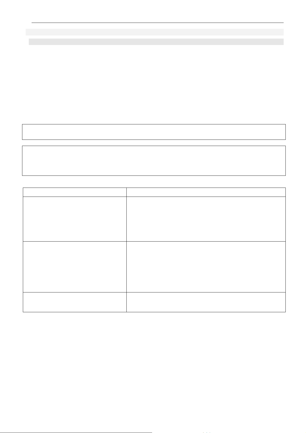
Type of fault
Check
No domestic hot water or central heating ~230-240V Supply (24HR)
~230-240V Supply (Off Peak)
System water pressure
Master high limit thermostat
Contactor
Reset-able Over Heat Thermostats
No central heating but hot water at
taps
Heating elements
~230-240V Supply (24HR)
~230-240V Supply (Off Peak)
External controls
Heating elements
Reset-able Over Heat Thermostats
Temperature at centre of store
setting of 30ºC
Central heating but no hot water at
taps or temperature diminishes after a
short period
Central heating pump
Auto air eliminator in closed position
Hot water mixing valve set too low or is faulty
must be above aqua stat
24

THERMAL INNOVATIONS (UK) LTD | THERMAFLOW® ELECTRIC COMBINATION BOILER | Tel: 0870 850 5207
Fault: No domestic hot water or central heating
Is there ~230-240V at the 24HR supply?
No
Is there ~230-240V at the off peak supply?
Yes
No
Is system pressure above 60 KPA (0.6 Bar)?
Yes
No
Is there continuity through master high limit stat?
Yes
No
Is there continuity through contactor?
Yes
No
Yes
Is there ~230-240V at each heating element and
continuity through thermostats within?
No
Check Fuse, MCB or Meter for correct
operation
Check Fuse or MCB
Increase Pressure
Replace Thermostat
Replace Contactor
Replace or re-set as necessary
25

THERMAL INNOVATIONS (UK) LTD | THERMAFLOW® ELECTRIC COMBINATION BOILER | Tel: 0870 850 5207
Fault: No central heating, but hot water at taps
Is there continuity through master high limit stat?
No
Yes
Replace Thermostat
Is there continuity through contactor?
Yes
Is there ~230-240V at each heating element and
continuity through thermostats within?
Yes
Are external controls calling for heat?
Yes
Is temperature above setting on aqua stat?
(Should be set to 30
o
C)
Yes
Is there ~230-240V and continuity at terminals of the
aqua stat?
Yes
No
No
No
No
No
Replace Contactor
Replace or re-set as necessary
Adjust the setting
Re-check when temperature increases
Check ~230V Supply
Is there ~230-240V supply at central Heating pump?
Yes
Is pump impeller turning?
Yes
Check thermostat and lock shield Valves on radiators are
open & calling for heat
No
No
Check for faulty external controls
Replace central heating pump
26

THERMAL INNOVATIONS (UK) LTD | THERMAFLOW® ELECTRIC COMBINATION BOILER | Tel: 0870 850 5207
Fault: CENTRAL HEATING BUT No hot water at taps
Is the automatic air eliminator on top of the boiler in the
open position causing an air trap in the top of the boiler?
Is the hot water mixing valve set correctly?
Replace hot water mixing valve
Yes
Yes
No
No
Open the small screw cap on top of the
auto air eliminator
Set to desired temperature
27

THERMAL INNOVATIONS (UK) LTD | THERMAFLOW® ELECTRIC COMBINATION BOILER | Tel: 0870 850 5207
WARNING: FOR YOUR OWN SAFETY
SERVICING AND MAINTENANCE SHOULD BE CARRIED OUT BY A PERSON WHO IS
COMPETENT TO DO SO.
3.2 ISOLATION
• Before commencing, refer to section 1. Installation
Checking the pressure in the expansion vessel
The primary expansion vessel (volume 25 litres) is the red or vessel connected to the central
heating return pipe or to the branch of the tee where the auto air vent is connected to on top of the
boiler. Its purpose is to take up expansion in the boiler and central heating system.
The pressure can be accurately checked with the pressure relieved on the other side of the
diaphragm. To do this drain some water from the central heating system until the pressure gauge
registers zero. Connect a pressure gauge to the car tyre type valve on the vessel. The pressure
should register 150 KPA (1.5 Bar). Refill heating system as described in section 2.7.2
The secondary expansion vessel (volume 1 or 2 litres) is the white or silver vessel connected to the
hot outlet of the pre-heat coil at the top of the boiler.
Its function is to take up expansion in the hot water pipe work and so protect the blender from
damage.
The pressure can be accurately checked with the pressure relieved on the other side of the
diaphragm. To do this, isolate the water supply to the Thermaflow and open a hot tap. Water will run
for a few seconds then stop.
Connect a pressure gauge to the car tyre type valve on the vessel. The pressure should register
100KPA (1.0 Bar) on the 1 litre vessel or 350 KPA (3.5 Bar) on the 2 litre vessel. Close the hot taps
and turn the water supply back on.
Checking the inline strainer
Whilst the water is off, remove and clean the gauze in the brass strainer assembly. To remove the
gauze for cleaning un-screw the brass plug.
Checking the hot water blending valve
With the store temperature fully recovered, run a hot tap and check the flow rate and temperature.
If the hot water has deteriorated suddenly (over less than a month) then this points to a problem
with the blender.
A broken blender is usually linked to a loss of pressure in the secondary expansion vessel. The
expansion vessel protects the blender from damage when the water in the secondary system
expands as the water re-heats after water is drawn off.
Check the pressure in the secondary expansion vessel as detailed previously in section 2. If it does
not hold pressure it will need to be changed along with the blender.
Strip off the blender and check hot and cold mesh filters for blockage. (Clean if necessary).
28

THERMAL INNOVATIONS (UK) LTD | THERMAFLOW® ELECTRIC COMBINATION BOILER | Tel: 0870 850 5207
Checking the concentration of corrosion inhibitor
We would recommend Sentinel X100, or equivalent. Dose appropriately according to the size of the
Thermaflow and central heating system volume combined and in accordance with the inhibitor
manufacturer’s guidelines.
Preventing pump seizure in summer
To prevent seizure of the central heating pump we recommend you turn the central heating on for
30 seconds or so every few weeks throughout the summer.
Seized pumps can usually be freed. The air release on the pump can be completely removed. A
small flat blade screwdriver can be inserted into the slot in the centre and rotated to free the pump.
Checking correct operation of electrical components
WARNING: BEFORE OBTAINING ACCESS TO TERMINALS, ALL SUPPLY CIRCUITS
MUST BE DISCONNECTED.
Low pressure switch
To check correct operation of the low pressure switch, drain some water from the central heating
system until the pressure falls below 0.5 bar, then check continuity between terminals 1 and 2 there
should be no continuity between these terminals. Re pressurise the boiler and re check there is
continuity between the same terminals.
Control and high limit thermostats
Check operation of the control and over temperature thermostats by checking for continuity between
both terminals. (YOU MAY HAVE TO REMOVE THESE THERMOSTATS IF THE BOILER IS STILL
HOLDING HOT WATER. YOU CAN PLACE THE THERMOSTATS IN A BEAKER OF COLD
WATER AND THEN CHECK FOR CONTINUITY ACROSS THE THERMOSTAT).
CONTROL THERMOSTATS; there are three or four of these thermostats in total, one in each
element. The control thermostats are individually preset and sealed; they should not be tampered
with. If a failure on one of the thermostats has occurred, take note of which element it was removed
from and contact Thermal Innovations (UK) Ltd for spares and advice.
OVER TEMPERATURE THERMOSTATS (Manual reset); there is also three or four of these, one in
each element. The over temperature thermostats are individually preset and sealed they should not
be tampered with. If a failure on one of the thermostats has occurred, reset the thermostat by
pressing the small reset button on the thermostat. If the thermostat continues to fail in an overheat
condition, take note of which element it was removed from and contact Thermal Innovations (UK)
Ltd for spares and advice.
There is also a non reset-able over temperature thermostat in the top enclosure this is the master
over temperature thermostat, this will break the circuit on over temperature it is preset and sealed
and should not be tampered with. This thermostat is not reset-able and will have to be replaced if it
has incurred an overheat situation). This will indicate a fault has occurred elsewhere and will
have to be investigated and rectified before the appliance is turned back on for use. If a
failure has occurred, contact Thermal Innovations (UK) Ltd for spares and advice.
Checking the elements
Check the continuity between live and neutral terminals on the element. Replace the element if
there is no continuity.
29

THERMAL INNOVATIONS (UK) LTD | THERMAFLOW® ELECTRIC COMBINATION BOILER | Tel: 0870 850 5207
Checking circuit breakers
Switch each circuit breaker off in turn and check that continuity is broken to each element.
Checking the contactor
Turn the main isolator off (this should be situated adjacent to the boiler) you should hear a dull
thump from the enclosure marked number 3 on the boiler schematic diagram 1.8.1. This indicates
that the contactor has disconnected the circuit to the MCB’s and in turn the heating elements. Turn
the main isolator on and off a few times and listen for this noise. This will indicate correct operation
of the contactor.
Check the operation of the AQUA STAT
The Aqua Stat is positioned at the entrance to the pre-heat coil on the cold water supply above the
top heating element on the boiler.
Make sure the external controls are calling for heat. Turn the dial
on the thermostat up and down and listen for a small click. As you turn the thermostat dial up and
down check if the central heating pump, (positioned on the right side of the unit) is switching
and
off. If this is the case, this indicates correct operation of the thermostat.
on
30
THERMAL INNOVATIONS (UK) LTD | THERMAFLOW® ELECTRIC COMBINATION BOILER | Tel: 0870 850 5207
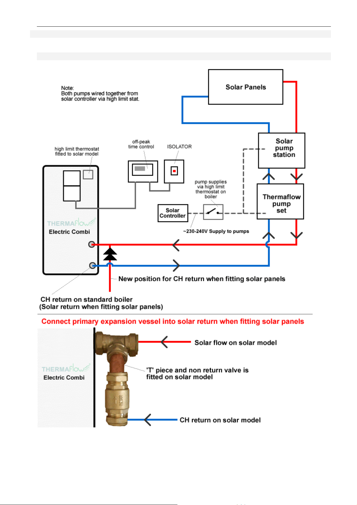
APPENDIX I – SOLAR CONNECTION
A1.1 Solar Pipe work Schematic
31

THERMAL INNOVATIONS (UK) LTD | THERMAFLOW® ELECTRIC COMBINATION BOILER | Tel: 0870 850 5207
A1.2 Solar/Off Peak Wiring Schematic
32
 Loading...