

Page 1

Thermedor '°A.A.,,,i,.._g,o.,.
iiV_ii¸ii13_,iiii3_,¸ii:i::::L:i_i!!_i:L_i,GViiiiiiii:_,_
Page 2
IMPORTANT SAFETY INSTRUCTIONS
Read All Instructions Before Using the Appliance.
READ AND SAVE THESE INSTRUCTIONS
WARNING- TO REDUCE THE RISK OFA RANGE
TOP GREASE FIRE:
a) Never leave surface units unattended at high
settings. Boilovers cause smoking and greasy a)
spillovers that may ignite. Heat oils slowly on
low or medium settings.
b) Always turn hood ON when cooking at high
heat or when flamb6ing food (i.e. Crepes
Suzette, Cherries Jubilee, Peppercorn Beef
Flamb6),
c) Clean ventilating fans frequently. Grease
should not be allowed to accumulate on fan or
filter,
d) Use proper pan size, Always use cookware
appropriate for the size of the surface element,
e) Do not place any objects on the snorkel. They d)
could fall down when the snorkel is raised.
Caution: Grease left on filters can remelt and move
into the vent,
When children become old enough to use the
appliance, it is the legal responsibility of the
parents or legal guardians to ensure that they
are instructed in safe practices by qualified
persons.
WARNING - TO REDUCE THE RISK OF INJURY
TO PERSONS IN THE EVENT OFACOOKTOP
GREASE FIRE, OBSERVE THE FOLLOWING:
b) NEVER PICK UPA FLAMING PAN. You may be
c) DO NOT USE WATER, including wet dish cloths
SMOTHER FLAMES with a close-fitting lid,
cookie sheet, or metal tray, then turn off the
burner. BE CAREFUL TO PREVENT BURNS.
If the flames do not go out immediately, EVACU-
ATE AND CALL THE FIRE DEPARTMENT.
burned.
or towels. A violent explosion will result,
Use an extinguisher ONLY if:
1 You know you have a Class ABC extin
guisher, and you already know how to
operate it,
2) The fire is small and contained in the area
where it started,
3) The fire department is being called,
4) You can fight the fire with your back to an
exit,
WARNING: Whenever possible, do not operate
blower during acooktop fire, However, DO NOT
REACH THROUGH FIRE TO TURN OFF BLOWER,
TABLE OF CONTENTS
Safety Instructions ....................... 2 Troubleshooting guide .................... 6
Operating Instructions .............. 3-4
Features ........................................... 3
Operation .......................................... 4
Care and Cleaning ........................ 5
PAGE 2
Customer Services ..................... 6-7
Before Calling for Service ................... 6
How to Obtain Service ....................... 6
Warranty ...................................... 7
Data Plate Information ....................... 7
Page 3
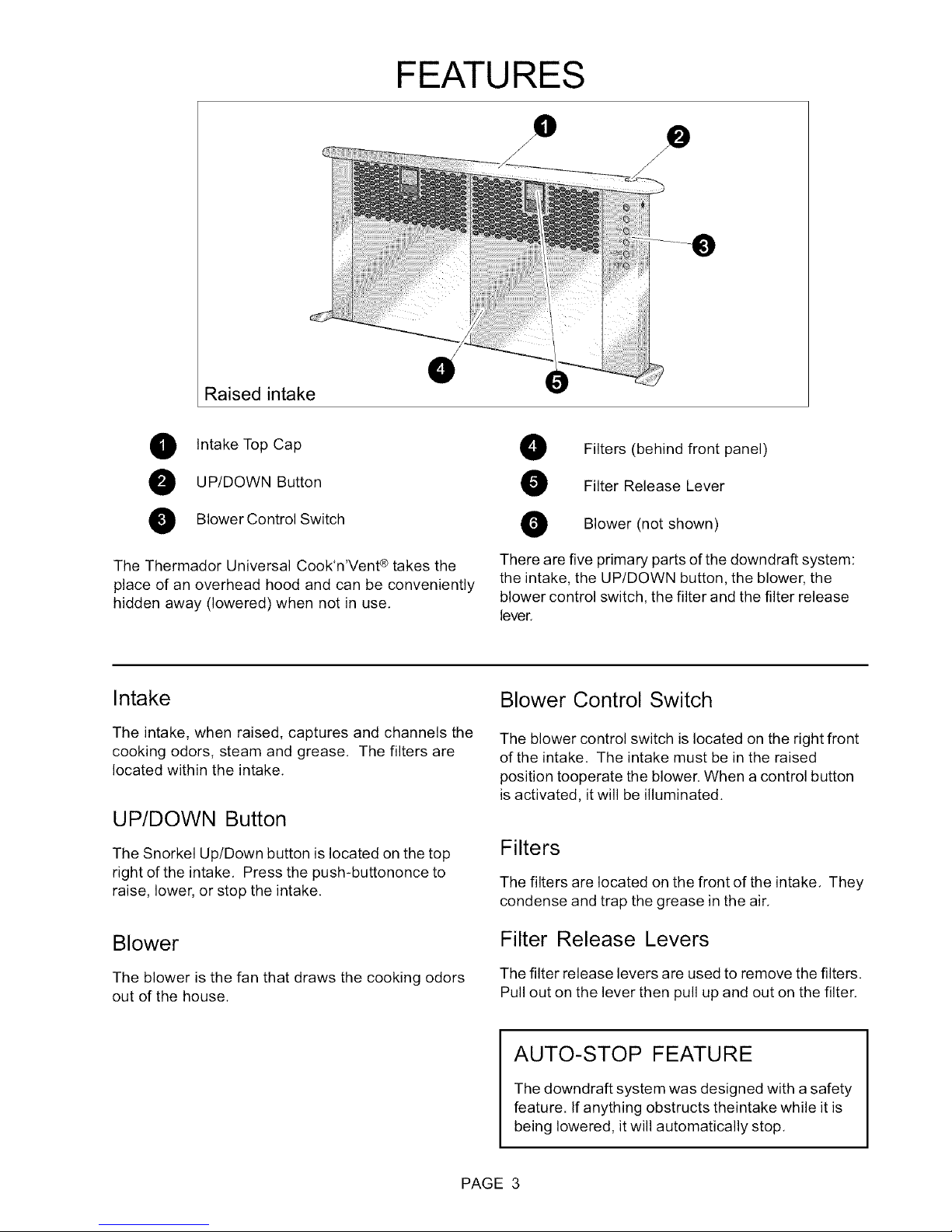
Raised intake
FEATURES
O
O Intake Top Cap
O UP/DOWN Button
O BIowerControl Switch
The Thermador Universal Cook'n'Vent ®takes the
place of an overhead hood and can be conveniently
hidden away (lowered) when not in use.
Intake
The intake, when raised, captures and channels the
cooking odors, steam and grease. The filters are
located within the intake.
UP/DOWN Button
The Snorkel Up/Down button is located on the top
right of the intake. Press the push-buttononce to
raise, lower, or stop the intake.
Filters (behind front panel)
Filter Release Lever
O Blower (not shown)
There are five primary parts of the downdraft system:
the intake, the UP/DOWN button, the blower, the
blower control switch, the filter and the filter release
lever.
Blower Control Switch
The blower control switch is located on the right front
of the intake. The intake must be in the raised
position tooperate the blower. When a control button
is activated, it will be illuminated.
Filters
The filters are located on the front of the intake. They
condense and trap the grease in the air.
Blower
The blower is the fan that draws the cooking odors
out of the house.
Filter Release Levers
The filter release levers are used to remove the filters.
Pull out on the lever then pull up and out on the filter.
AUTO-STOP FEATURE
The downdraft system was designed with a safety
feature. If anything obstructs theintake while it is
being lowered, it will automatically stop.
PAGE 3
Page 4

OPERATION
Snorkel Up/Down
Pushing the Snorkel Up/Down moves the intake up or down. Pushing this button while
snorkel is raising or lowering will stop motion. Pushing again will reverse motion.
Blower Off
Off- Pressing once turn the ventilator offand resets the Time Delay Blower Shut Off.
High Blower Speed ]
Medium Blower Speedq
Low Blower Speed J
Delay Shut Off
Pressing the Delay Shut Off button will turn the current speed off after 10minutes of use. If
the ventilator is offwhen this button is pressed, the ventilator will turn on high for
10 minutes. Pressing the Delay Shut Off button, Blower Off button or changing the ventila-
tor speed during a timed mode turns offthe timer.
Clean Filter Reminder
After 40 hours of operation the Clean Filter Reminder button will illuminate. At this time the
filters need to be cleaned. Once the filters have been cleaned, press and hold this button
tor three seconds to reset,
For Best Results
Turn the blower on before starting to cook,
A higher heat setting may be needed when the
downdraft is in operation,
Use arear burner when browning or pan frying meat,
Open a window or inside door slightly,
Clean the filters and the wall behind the filters
frequently.
For Gas Cooktops, a lower blower speed should
be used if:
the gas flame is being distorted by the air
movement.
the burner continually sparks (clicks)
the burner flame repeatedly blows out,
To Raise the Intake
Press the UP/DOWN push-button once to raise
the intake,
The intake will stop automatically at its maximum
height.
The blower will automatically turn on to the
previously set blower speed,
Pressing the High, Medium, or Low Blower Speed
buttons will turn on or change the ventilator speed to the
corresponding button selected.
To Set or Adjust Blower Speed
Vary the blower speed as needed for the food or
the cooking method being used. For example:
greasy or pungent foods require greater ventila-
tion power than boiling pasta,
To Lower the Intake
Press the UP/DOWN push-button once.
Note: The blower will turn off when the intake is
lowered if operating when the UP/DOWN push-
button is pressed.
To Stop Intake While It is Moving
Press the Snorkel Up/Down button once.
The intake will stop.
Press the Snorkel Up/Down button again to
reverse direction.
PAGE 4
Page 5

CARE AND CLEANING
The efficiency of the downdraft ventilation system depends on the cleanliness of the intake and filters. The
frequency of cleaning depends on the amount and type of cooking,
Do not use the ventilating system without the filters in place or with grease-laden filters or surfaces.
,_ WARNING Toavoid risk of fire and explosion do not use flammable liquids or solvents.
Always unplug ordisconnect the appliance from the power supply before servicing.
To Remove Filters
1. Pull out on lever,
2. Lift filter up and out.
3. Clean filters in the dishwasher or in warm, sudsy
water. See Care and Cleaning Chart, next page,
for further details.
To Replace Filters
1. Place bottom of filter in grease trough,
2. Pull out on lever,
3. Press top of filter into place,
4. Release Lever.
Ifa spill occurs on the cooktop that allows liquids to seep inside the downdraft, you must turn the downdraft off
immediately. It is possible to cause damage to the downdraft if water is allowed inside the downdraft while it is
operating.
Immediately turn OFF the downdraft at the speed control located on the right-hand side of the downdraft,
Turn OFF the power supply to the downdraft at the circuit breaker box or fuse box,
Allow plenty of time for the downdraft to dry naturally, Do not open the downdraft to remove the water.
Always use the mildest cleaner that will do the job. Use clean, soft cloths, sponges or paper towels.
Rub stainless steel finishes in the direction of the grain. Wipe area dry to avoid water marks.
After cleaning, place all parts in their proper positions before using.
The cleaners recommended below indicate a type and do not constitute an endorsement, Use all products
according to package directions,
To Clean the Intake and Grease
Troughs
Intake must be in the raised position to clean.
1. Turn off the blower,
2. Remove filters.
3, Clean intake and grease troughs with general
household degreaser spray or cleaner.
4, Rinseand dry.
5, Replace filters,
Care and Cleaning Chart
A Anodized Top cap is not removable, Wash top and underside with hot sudsy water. Rinse and
Aluminum wipe dry or apply Fantastic ®or Formula 409®first to a clean sponge or paper towel
Top Cap for and wipe clean. DO NOT USE powdered cleansers or steel wool pads.
Stainless
B Aluminum Clean filters in the dishwasher or by agitating in sudsy water, Ensure that there is
Mesh Filters no soil trapped in the fine mesh. Dry the filters before reinstalling them.
C Plastic DO NOT REMOVE push-button or control knob. Wipe with a moist soapy sponge.
Controls Rinse and dry. DO NOT USE powdered cleansers or steel wool pads.
D Stainless
Steel Parts
Wipe grease accumulation with a paper towel or sponge, Scrape heavy buildup with
a plastic spatula. Clean with a soapy sponge; rinse and dry. Always wipe or rub with
grain, Wipe with Fantastik ®or Formula 409 ®sprayed onto a paper towel, If
grease buildup is heavy, several applications may be necessary,
Polish with Stainless Steel Magic ®and a soft cloth. Remove water spots with a cloth
dampened with white vinegar, Use CameoAluminum and Stainless Steel Cleaner ¢
to remove heat discoloration.
PAGE 5
Page 6

TROUBLESHOOTING GUIDE
Problem Possible Cause Remedy
Intake Stopped Obstruction Remove obstruction, press
Snorkel Up/Down button to raise
intake, then press again to lower
intake.
Nothing works - all buttons are
illuminated
Nothing works - no buttons are
illuminated
Clean Filter Reminder button
illuminates
CUSTOMER SERVICES
Intake encountered an obstruction
on the way up & timed out,
Control button board has become
disconnected.
Reactive the controls by pressing
the Delay Shut Off button first then
the Blower Off button second.
Press the Snorkel Up/Down button
to continue operation. If intake is
so low that control buttons are not
accessible, reset by unplugging
and plugging,
*If problem persists, leave intake
in the current position and
contact electrician or qualified
appliance service technician.
Contact qualified appliance
service technician.
Clean filters, then press and
hold the Clean Filter Reminder
button for three seconds to
reset,
Before Calling for Service
If the blower does not operate:
Ensure that the electrical cord is properly connected and the supply circuit is energized.
Check that the intake is fully raised.
Make sure that the blower speed control knob is not in the OFF position.
How to Obtain Service
For authorized service or parts information, call 1-800-735-4328.
We want you to be a satisfied customer, If a situation arises that has not been resolved to your satisfaction,
please let us know,
Write: Customer Support, BSH Home Appliances, Corp. 5551 McFadden Ave., Huntington Beach, CA
92649, or call: 1-800-735-4328,
Please include the model number, serial number, and date of original purchase/installation.
PAGE 6
Page 7

Warranty
CUSTOMER SERVICES
What is Covered
Full One Year Warranty
For one year from the date of installation or date of
occupancy for a new previously unoccupied dwell-
ing, any part which fails in normal home use will be
repaired or replaced free of charge, Save your
dated receipt or other evidence of the installation/
occupancy date. BSH will pay for all repair labor
and replacement parts found to be defective due to
materials and workmanship, Service must be
provided by a BSH Authorized Service Agency
during normal working hours,
What is not Covered
1, Service by an unauthorized agency, Damage or
repairs due to service by an unauthorized
agency or the use of unauthorized parts,
2, Service visits to:
Teach you how to use the appliance,
Correct the installation, You are respon-
sible for providing electrical wiring and
other connecting facilities,
Reset circuit breakers or replace home
fuses.
3. Damage resulting from accident, alteration,
misuse, abuse, improper installation or installa-
tion not in accordance with local electrical codes
or plumbing codes, or improper storage of the
appliance,
4. Repairs due to other than normal home use.
Warranty Application
This warranty applies to appliances used in normal
family households, It does not cover their use in
commercial situations,
This warranty is for products purchased and retained
in the 50 states of the U.S.A., the District of Colum-
bia and Canada. The warranty applies even if you
should move during the warranty period. Should the
appliance be sold by the original purchaser during
the warranty period, the new owner continues to be
protected until the expiration date of the original
purchaser's warranty period,
BSH DOES NOT ASSUME ANY RESPONSIBILITY
FOR INCIDENTAL OR CONSEQUENTIAL DAM-
AGES, Some states do not allow the exclusion or
limitation of incidental or consequential damages, so
the above limitation or exclusion may not apply to
you. This warranty gives you specific legal rights
and you may also have other rights which may vary
from state to state or province to province.
Service Data
For handy reference, the serial tag information has
been affixed below, Keep your invoice for warranty
validation. To obtain service, see previous page.
We reserve the right to change specifications or design without notice, Some models are certified for use in
Canada. BSH is not responsible for products which are transported from the U.S. for use in Canada. Check
with your local Canadian distributor or dealer.
Serial NumberlData Plate Location: Above Electrical Connection
Box. See Page 6.
PAGE 7
Page 8

Thermedor AoA_,_,c.o3coo,_
5551 McFadden Avenue, Huntington Beach, CA 92649 • 800/735-4328
9000160192 • 10013 RevB • 07/06 © BSH Home Appliances 2005 • Litho en U. S. A.
 Loading...