

Page 1
1
1
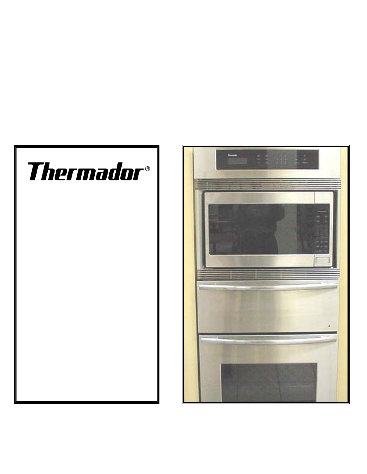
SMW
Series
Oven
Training
Program
SMW
SMW
Series
Series
Oven
Oven
Training
Training
Program
Program
Page 2

2
2
SMW Series Oven
Training Program
SMW Series Oven
SMW Series Oven
Training Program
Training Program
ä
ä
Installation
Installation
ä
ä
Features and Operation
Features and Operation
ä
ä
Model Numbers
Model Numbers
ä
ä
Warranty
Warranty
ä
ä
Component Description and Access
Component Description and Access
ä
ä
Error Codes
Error Codes
ä
ä
How the Oven Works….Microwave Section
How the Oven Works….Microwave Section
ä
ä
How the Oven Works….Warming Drawer Section
How the Oven Works….Warming Drawer Section
ä
ä
How the Oven Works….Lower Convection Oven
How the Oven Works….Lower Convection Oven
ä
ä
Service Tips
Service Tips
Page 3

3
3
Installation
Installation
Electrical Power Connection
Electrical Power Connection
•• Requires four wire supply L1, L2, Neutral and a bare ground
Requires four wire supply L1, L2, Neutral and a bare ground
Some local codes permit grounding through the neutral
Some local codes permit grounding through the neutral
•• 30 amp circuit breaker
30 amp circuit breaker
•• Unit is dual-rated, 120/208-240 volts
Unit is dual-rated, 120/208-240 volts
Cut-out Dimensions
Cut-out Dimensions
•• Height 55-3/8 inches
Height 55-3/8 inches
•• Width 25-1/2 inches
Width 25-1/2 inches
•• Depth 24 inches
Depth 24 inches
•• Floor to cutout 9-3/4 inches
Floor to cutout 9-3/4 inches
Page 4

4
4
Installation…continued
Installation…continued
•• Electrical conduit box
Electrical conduit box
The preferred location
The preferred location
would be to install it 2-1/2 inches above the unit, in
would be to install it 2-1/2 inches above the unit, in
the center of the cabinet. However it may be
the center of the cabinet. However it may be
placed approx. 5 inches below cabinet base.
placed approx. 5 inches below cabinet base.
•• Cabinet base
Cabinet base
must be capable of supporting the
must be capable of supporting the
weight of the unit, approx. 250 pounds.
weight of the unit, approx. 250 pounds.
•• Frame
Frame
of oven overlaps the cabinet by 5/8 inch.
of oven overlaps the cabinet by 5/8 inch.
•• Oven
Oven
should be installed in such a manner that it
should be installed in such a manner that it
can be easily removed for service
can be easily removed for service
•• Internal
Internal
ventilation system
ventilation system
Page 5

5
5
Features and Operation
Features and Operation
Features and Operation
ä
ä
Upper oven
Upper oven
features a 2.1 cubic foot microwave
features a 2.1 cubic foot microwave
ä
ä
1100 watts of power with sensor cooking & 10 power levels
1100 watts of power with sensor cooking & 10 power levels
ä
ä
Language choice for display: English, French & Spanish
Language choice for display: English, French & Spanish
ä
ä
Weight can be displayed in either
Weight can be displayed in either
Lbs
Lbs
..or
..or
Kgs
Kgs..
ä
ä
Child lock-out feature
Child lock-out feature
ä
ä
Demo mode on/off for retail store display
Demo mode on/off for retail store display
ä
ä
Auto popcorn feature, can be pre-set according to weight
Auto popcorn feature, can be pre-set according to weight
ä
ä
Middle oven
Middle oven
is a warming drawer keeps food at desired
is a warming drawer keeps food at desired
temperature until ready to serve: Temperature controls are from
temperature until ready to serve: Temperature controls are from
a high of 240F to a low of 140F
a high of 240F to a low of 140F
Page 6

6
6
Features and Operation
Features and Operation
Features and Operation
ä
ä
Lower oven
Lower oven
is a S Series convection oven with 4 modes of
is a S Series convection oven with 4 modes of
cooking
cooking
ä
ä
Bake, Variable Broil, Convection and Convection Roast
Bake, Variable Broil, Convection and Convection Roast
ä
ä
Sense-A-Touch glass control panel
Sense-A-Touch glass control panel
ä
ä
Halogen oven lights
Halogen oven lights
ä
ä
Large viewing window
Large viewing window
ä
ä
Two separate timers
Two separate timers
ä
ä
Timed cooking mode
Timed cooking mode
ä
ä
Six adjustable rack positions
Six adjustable rack positions
ä
ä
Oven comes with 3 racks
Oven comes with 3 racks
ä
ä
Rack supports are porcelain & removable
Rack supports are porcelain & removable
Page 7

7
7
Features
Features
Features
ä
ä
Oven & door liner...fine grain porcelain
Oven & door liner...fine grain porcelain
enamel
enamel
ä
ä
Two 10W 12VAC Halogen lights per
Two 10W 12VAC Halogen lights per
cavity
cavity
ä
ä
Equivalent to a 60W incandescent
Equivalent to a 60W incandescent
bulb
bulb
Page 8
8
8
Features and Operation
Features and Operation
Features and Operation
ä
ä
Panel Lock (child lockout)
Panel Lock (child lockout)
ä
ä
A 12 or 24 hour clock option
A 12 or 24 hour clock option
ä
ä
Centigrade or fahrenheit temperature display
Centigrade or fahrenheit temperature display
ä
ä
3 Specialty Modes
3 Specialty Modes
ä
ä
Proof
Proof
ä
ä
Cycles bake circuits at 100 degrees
Cycles bake circuits at 100 degrees
ä
ä
Dehydrate…
Dehydrate…
ä
ä
Cycles convection circuits at 140 degrees
Cycles convection circuits at 140 degrees
Page 9

9
9
Features and Operation
Features and Operation
Features and Operation
ä
ä
Sabbath….
Sabbath….
ä
ä
only available in bake cycle
only available in bake cycle
ä
ä
element indicator light cycles with heat
element indicator light cycles with heat
ä
ä
all other keys/functions are dead except off key
all other keys/functions are dead except off key
Page 10

10
10
Model Numbers
Model Numbers
Model Numbers
ä
ä
27” Integrated Electric Oven, Warming Drawer &
27” Integrated Electric Oven, Warming Drawer &
Microwave Oven
Microwave Oven
ä
ä
4 Models
4 Models
ä
ä
SMW272YB………Black Glass
SMW272YB………Black Glass
ä
ä
SMW272YW………White Glass
SMW272YW………White Glass
ä
ä
SMW272YS……….Stainless Steel
SMW272YS……….Stainless Steel
ä
ä
SMW272YP……….Stainless Steel with Pro
SMW272YP……….Stainless Steel with Pro
Stainless steel handle
Stainless steel handle
Page 11

11
11
Model Numbers
Example….SMW272YB
Model Numbers
Model Numbers
Example….SMW272YB
Example….SMW272YB
ä
ä
S =
S =
S-Series convection oven
S-Series convection oven
ä
ä
M =
M =
Microwave oven
Microwave oven
ä
ä
W =
W =
Warming drawer
Warming drawer
ä
ä
27 =
27 =
27” Oven
27” Oven
ä
ä
2 =
2 =
Double oven
Double oven
ä
ä
Y =
Y =
2000 Introduction Year
2000 Introduction Year
ä
ä
The Y designates a change in
The Y designates a change in
form & finish
form & finish
(appearance)
(appearance)
from previous designated year
from previous designated year
ä
ä
The serial number is used to denote a change in internal
The serial number is used to denote a change in internal
components
components
ä
ä
B =
B =
Black
Black
Page 12

12
12
Warranty
Warranty
Warranty
ä
ä
One full year
One full year
from date of installation or
from date of installation or
occupancy
occupancy
ä
ä
Service must be performed
Service must be performed
by an
by an
authorized service agent
authorized service agent
ä
ä
Warranty Claim
Warranty Claim
must be submitted within 45
must be submitted within 45
days of completion
days of completion
Page 13

13
13
ä
ä
Microwave section
Microwave section
ä
ä
Microwave vent-cover
Microwave vent-cover
ä
ä
Touch control door assembly… includes
Touch control door assembly… includes
membrane switch & DPC (
membrane switch & DPC (
Digital Programmer
Digital Programmer
Control)
Control)
ä
ä
Inverter board
Inverter board
ä
ä
Lamp &
Lamp &
mag
mag
tube
tube
ä
ä
Stirrer motor
Stirrer motor
ä
ä
Troubleshooting
Troubleshooting
Microwave Oven Section
Microwave Oven Section
…..
…..
component description & access
component description & access
Page 14
14
14
Microwave Section…Removal
Microwave Section…
Microwave Section…
Removal
Removal
ä
ä
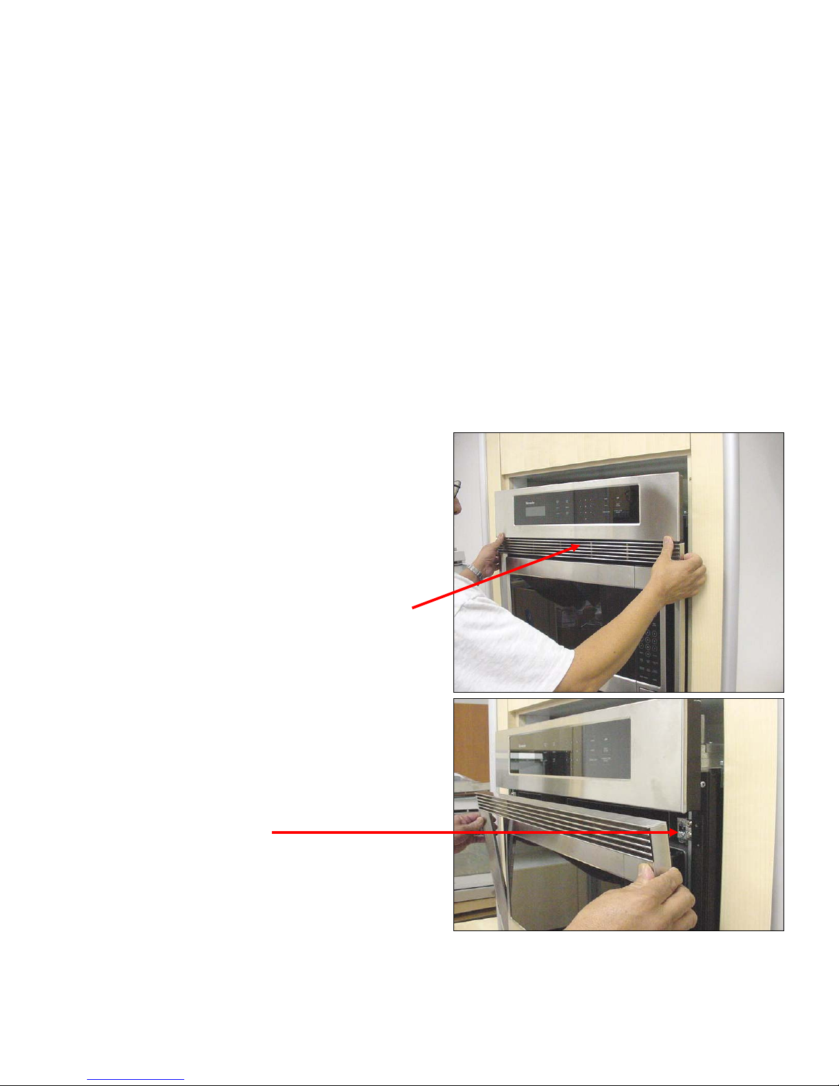
To gain access to the
To gain access to the
microwave section
microwave section
ä
ä
Remove vent frame from
Remove vent frame from
around the microwave
around the microwave
unit. This frame is a one
unit. This frame is a one
piece construction
piece construction
ä
ä
Grasp the frame and pull
Grasp the frame and pull
the ball studs from the
the ball studs from the
spring catches
spring catches
14
14
Page 15
15
15
Microwave Section…Removal
Microwave Section…
Microwave Section…
Removal
Removal
ä
ä
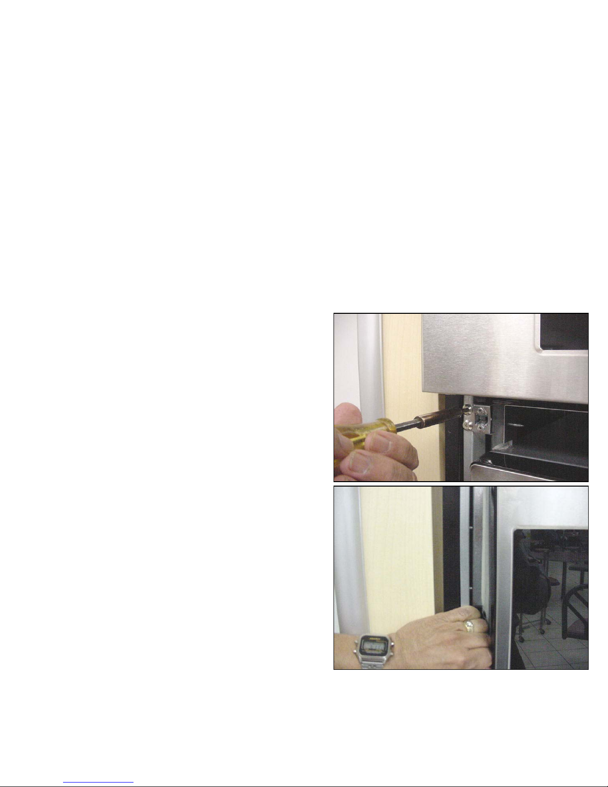
Remove the 2 screws
Remove the 2 screws
which hold the microwave
which hold the microwave
base to the oven housing
base to the oven housing
ä
ä
Remove the spring catches,
Remove the spring catches,
which are secured with
which are secured with
two screws
two screws
ä
ä
Bow out the side of outer
Bow out the side of outer
frame slightly to allow the
frame slightly to allow the
section to slide out easily
section to slide out easily
15
15
Page 16
16
16
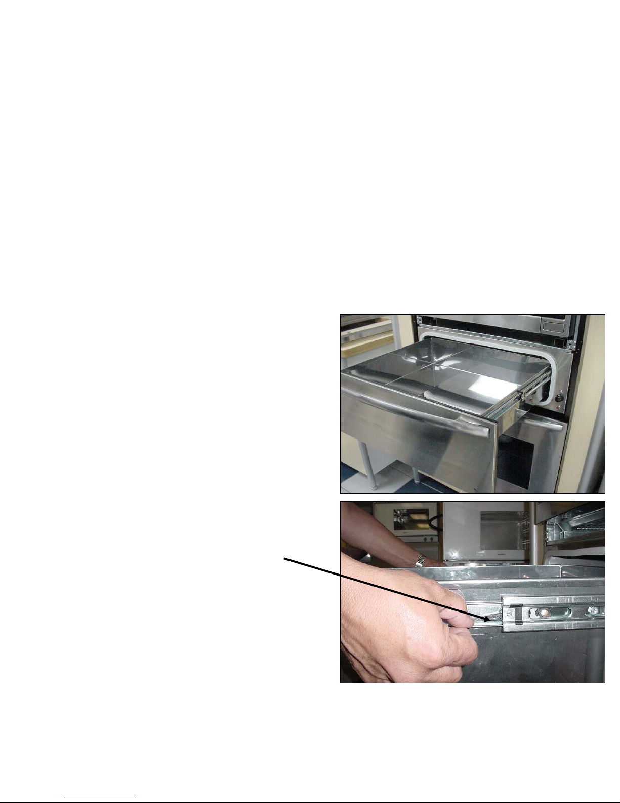
Microwave Section…Removal
Microwave Section…
Microwave Section…
Removal
Removal
ä
ä
Before removing
Before removing
section, remove
section, remove
warming drawer to
warming drawer to
avoid scratching
avoid scratching
ä
ä
Slide tabs on both
Slide tabs on both
sides of rails and
sides of rails and
drawer will pull out
drawer will pull out
16
16
Page 17
17
17
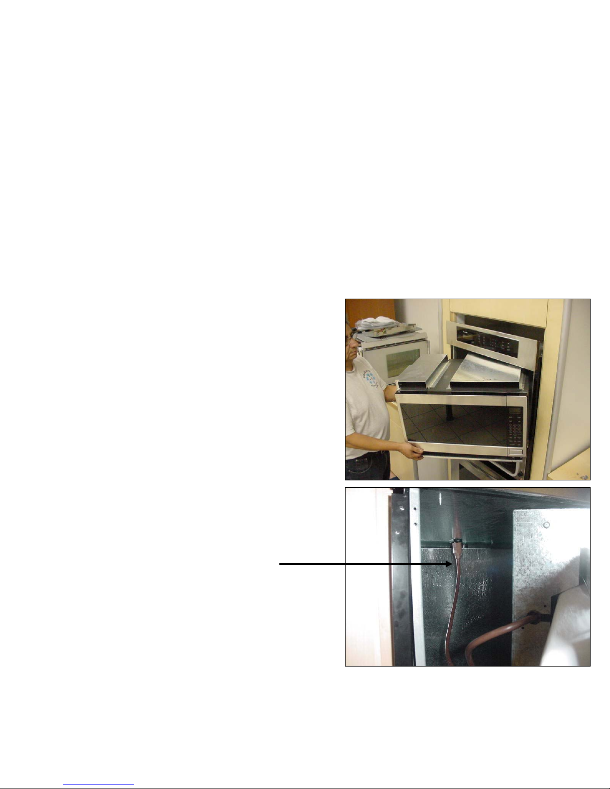
Microwave Section…Removal
Microwave Section…
Microwave Section…
Removal
Removal
ä
ä
Slide section part way
Slide section part way
out leaving the right
out leaving the right
rear corner still inside
rear corner still inside
housing
housing
ä
ä
While holding front of
While holding front of
unit reach inside and
unit reach inside and
unplug the section
unplug the section
from the receptacle
from the receptacle
17
17
Page 18
18
18
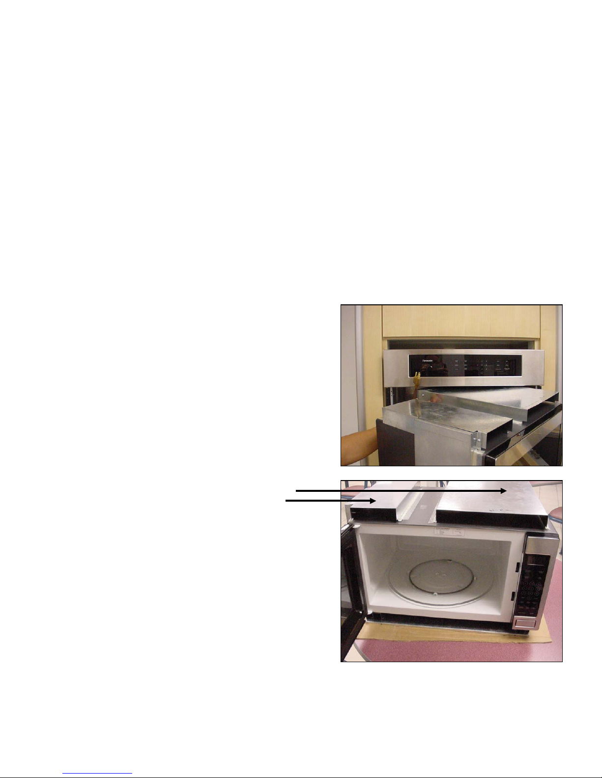
Microwave Section …Removal
Microwave Section …
Microwave Section …
Removal
Removal
ä
ä
Section can now be
Section can now be
removed completely
removed completely
and set down on a
and set down on a
solid surface
solid surface
ä
ä
Note the exhaust duct
Note the exhaust duct
covers on the top of
covers on the top of
the microwave cover
the microwave cover
18
18
Page 19
19
19
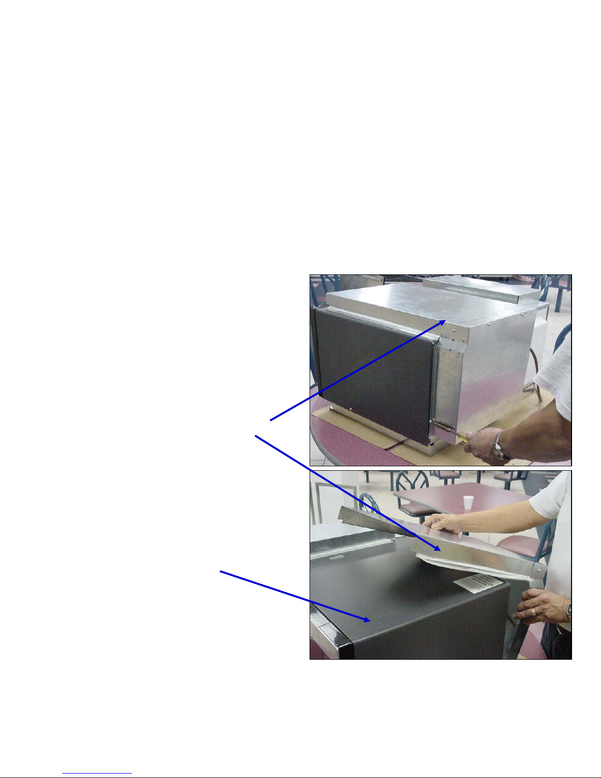
Microwave Section…Access Duct Cover
Microwave Section…
Microwave Section…
Access Duct Cover
Access Duct Cover
ä
ä
To gain access to the
To gain access to the
microwave components
microwave components
the duct exhaust parts
the duct exhaust parts
must first be removed
must first be removed
from the microwave
from the microwave
cover
cover
ä
ä
The microwave cover can
The microwave cover can
then be removed
then be removed
19
19
Page 20
20
20
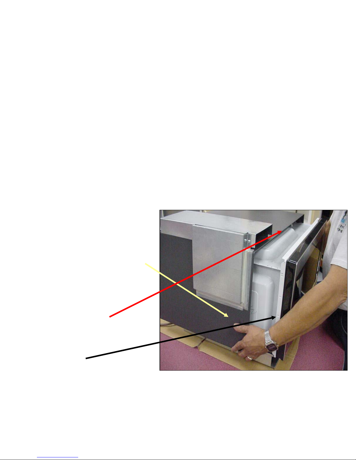
Microwave Section…Access Outer Cover
Microwave Section…
Microwave Section…
Access Outer Cover
Access Outer Cover
ä
ä
After removing the
After removing the
screws from the sides
screws from the sides
and rear, the cover slides
and rear, the cover slides
away from the front
away from the front
allowing access to most
allowing access to most
of the components.
of the components.
ä
ä
Note the groove on the
Note the groove on the
cover and the tab on the
cover and the tab on the
front frame
front frame
Page 21
21
21
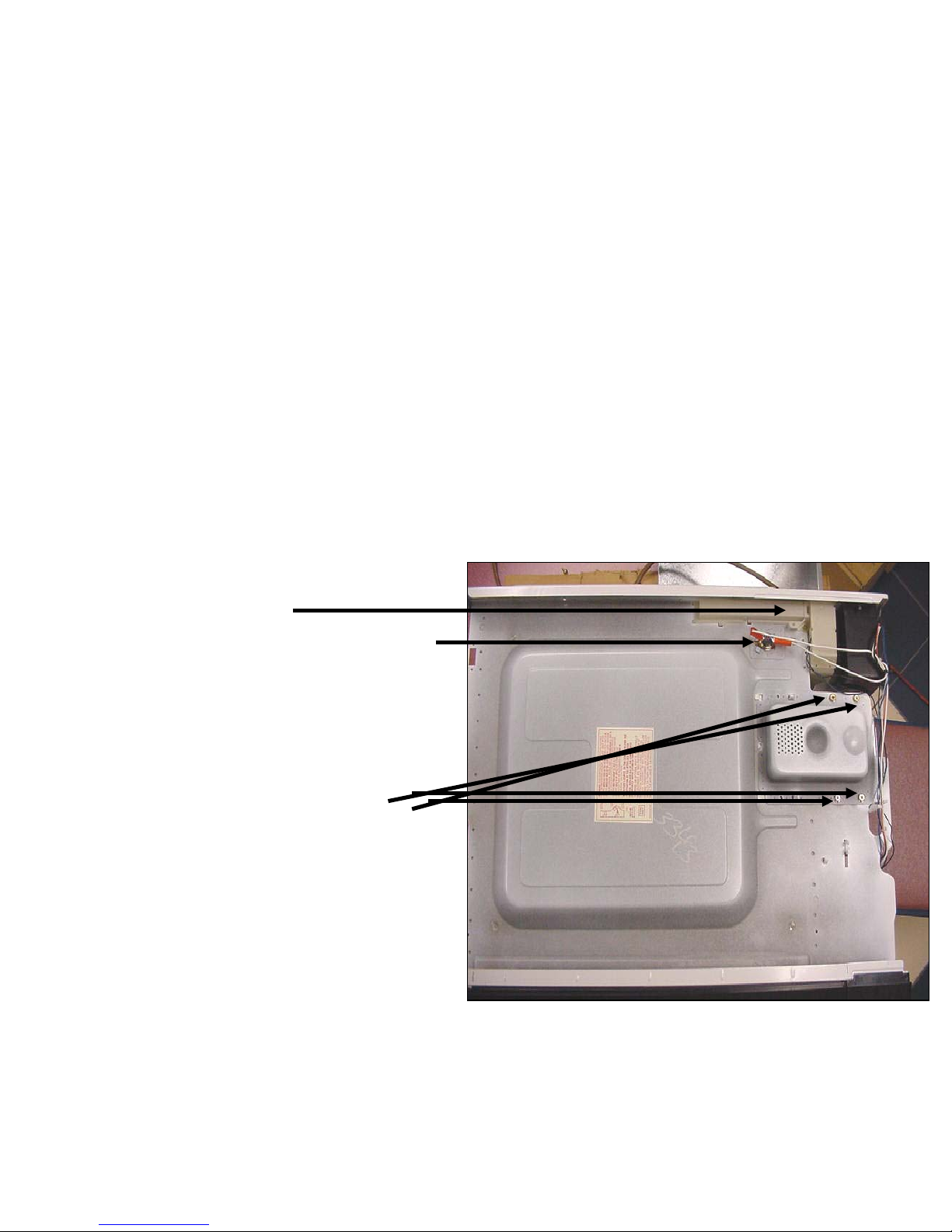
Component Description & Access…Mag
tube & Mag tube thermal cutout
Component Description &
Component Description &
Access
Access
…
…
Mag
Mag
tube &
tube &
Mag
Mag
tube thermal cutout
tube thermal cutout
ä
ä
Steam Sensor Location
Steam Sensor Location
( inside cover)
( inside cover)
ä
ä
Mag
Mag
-tube thermal cutout
-tube thermal cutout
N/C opens at 105
N/C opens at 105
deg
deg
.C
.C
ä
ä
Mag
Mag
tube is secured with
tube is secured with
four screws. Across
four screws. Across
filament terminals should
filament terminals should
read 1 Ohm or less.
read 1 Ohm or less.
Between each terminal
Between each terminal
and ground should be
and ground should be
open
open
Page 22
22
22
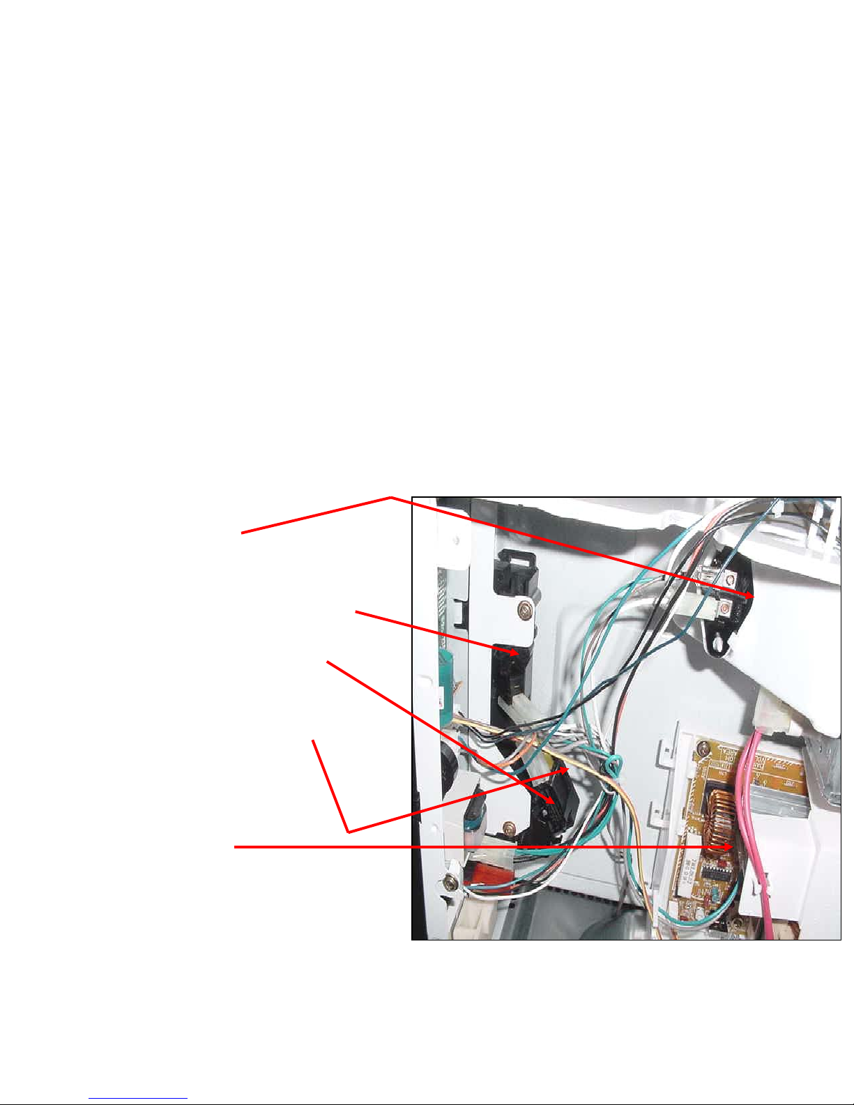
Component Description & Access….
Door switches and lamp assembly
Component Description &
Component Description &
Access….
Access….
Door switches and lamp assembly
Door switches and lamp assembly
ä
ä
Lamp assembly
Lamp assembly
lamp is 20watts 120V
lamp is 20watts 120V
ä
ä
Primary latch switch N/O
Primary latch switch N/O
ä
ä
Secondary latch switch N/O
Secondary latch switch N/O
& is the outside switch
& is the outside switch
ä
ä
Monitor or short switch N/C
Monitor or short switch N/C
& is the inside switch
& is the inside switch
ä
ä
Inverter board
Inverter board
22
22
Page 23
23
23
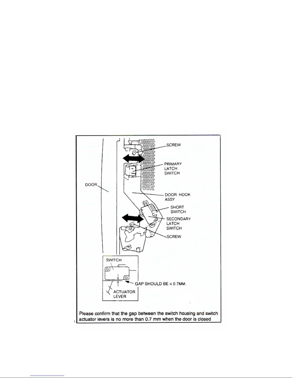
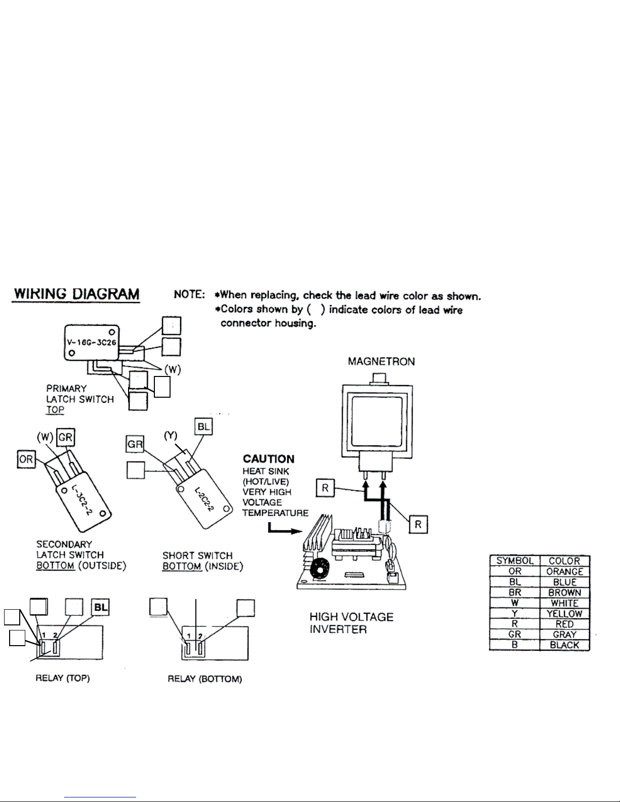
Microwave Section….
Microwave Section….
Door Switch Locations & Adjustments
Door Switch Locations & Adjustments
Page 24
24
24
SMW Microwave switch & relay wiring
SMW Microwave switch & relay wiring
N/O
N/O
Switch
Switch
N/C
N/C
Switch
Switch
N/O Switch
N/O Switch
CCN/O
N/O
W
W
W
W
B
B
B
B
B
B
GR
GR
GR
GR
W
W
W
W
BL
BL
B
B
OR
OR
24
24
(R)
(R)
(W)
(W)
BR
BR
(W) White (Y) Yellow (R) Red
(W) White (Y) Yellow (R) Red
Page 25
25
25
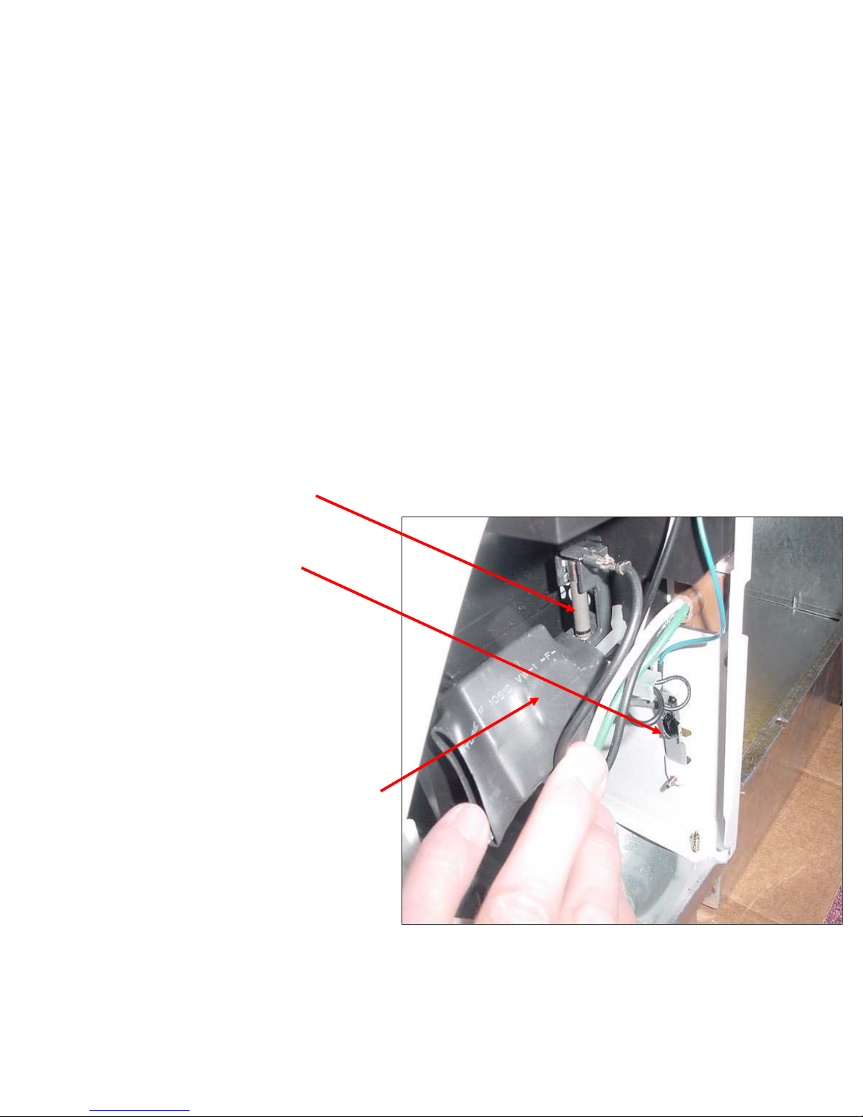
Component Description &
Access….Fuse Temp. Sensor & Noise Filter
Component Description &
Component Description &
Access….Fuse Temp. Sensor & Noise Filter
Access….Fuse Temp. Sensor & Noise Filter
ä
ä
Fuse is rated at 18 amps
Fuse is rated at 18 amps
( regular cartridge fuse )
( regular cartridge fuse )
ä
ä
Temperature sensor
Temperature sensor
measures 40,000 Ohms to
measures 40,000 Ohms to
ground If excessive cabinet
ground If excessive cabinet
temperature is detected
temperature is detected
cooling fan will turn on
cooling fan will turn on
automatically until temp.
automatically until temp.
drops
drops
ä
ä
Noise filter is across hot and
Noise filter is across hot and
neutral incoming supply
neutral incoming supply
Page 26

26
26
Component Description & Access…
Microwave Touch Control Door Assembly
Component Description &
Component Description &
Access…
Access…
Microwave Touch Control Door Assembly
Microwave Touch Control Door Assembly
ä
ä
Before removing door
Before removing door
assembly
assembly
disconnect the four
disconnect the four
plug connectors, the ribbon
plug connectors, the ribbon
connector and the two relay
connector and the two relay
plugs.
plugs.
(all connection plugs are color
(all connection plugs are color
coded so that they can’t be
coded so that they can’t be
mis
mis
-wired)
-wired)
ä
ä
To remove assembly
To remove assembly
remove
remove
the two screws from the top
the two screws from the top
and the single screw from the
and the single screw from the
side of the frame
side of the frame
ä
ä
Door assembly
Door assembly
will then lift
will then lift
up and out of the slots in the
up and out of the slots in the
frame
frame
26
26
Page 27
27
27
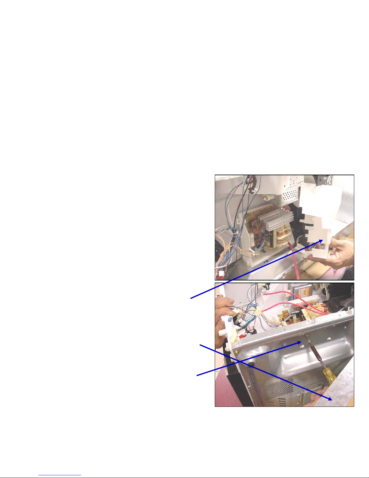
Component Description &
Access….High Voltage Inverter
Component Description &
Component Description &
Access….High Voltage Inverter
Access….High Voltage Inverter
ä
ä
To gain access to the Inverter
To gain access to the Inverter
Power Supply Board
Power Supply Board
disconnect the
disconnect the
mag
mag
tube HV
tube HV
wires
wires
ä
ä
Unsnap the plastic air guide
Unsnap the plastic air guide
from the tabs
from the tabs
ä
ä
To remove board remove m/w
To remove board remove m/w
pan (4 screws at the corners &
pan (4 screws at the corners &
3 across the rear) then the 3
3 across the rear) then the 3
screws which secure the board
screws which secure the board
27
27
Page 28
28
28
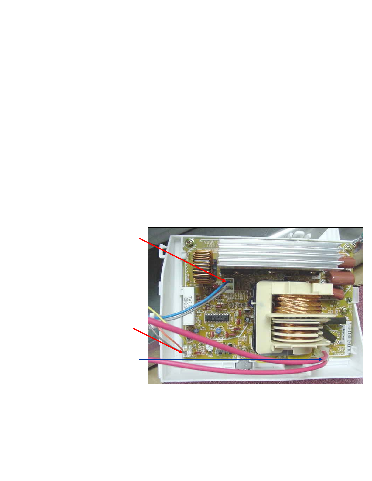
Component Description &
Access…High Voltage Inverter Terminals
Component Description &
Component Description &
Access…High Voltage Inverter Terminals
Access…High Voltage Inverter Terminals
ä
ä
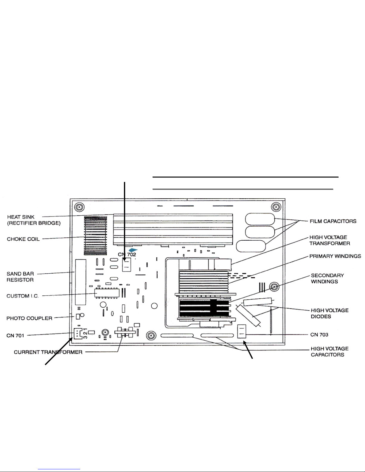
CN702
CN702
…120VAC
…120VAC
input to transformer
input to transformer
ä
ä
CN701
CN701
…Signal
…Signal
voltage from DPC
voltage from DPC
circuit (3 wire plug)
circuit (3 wire plug)
Voltage varies from 0
Voltage varies from 0
volts to 2.7VAC for
volts to 2.7VAC for
variable power levels
variable power levels
ä
ä
CN703
CN703
…4000VDC
…4000VDC
output to
output to
mag
mag
tube
tube
Page 29
29
29
Microwave Section….Inverter Power supply HV Area
Microwave Section….Inverter Power supply HV Area
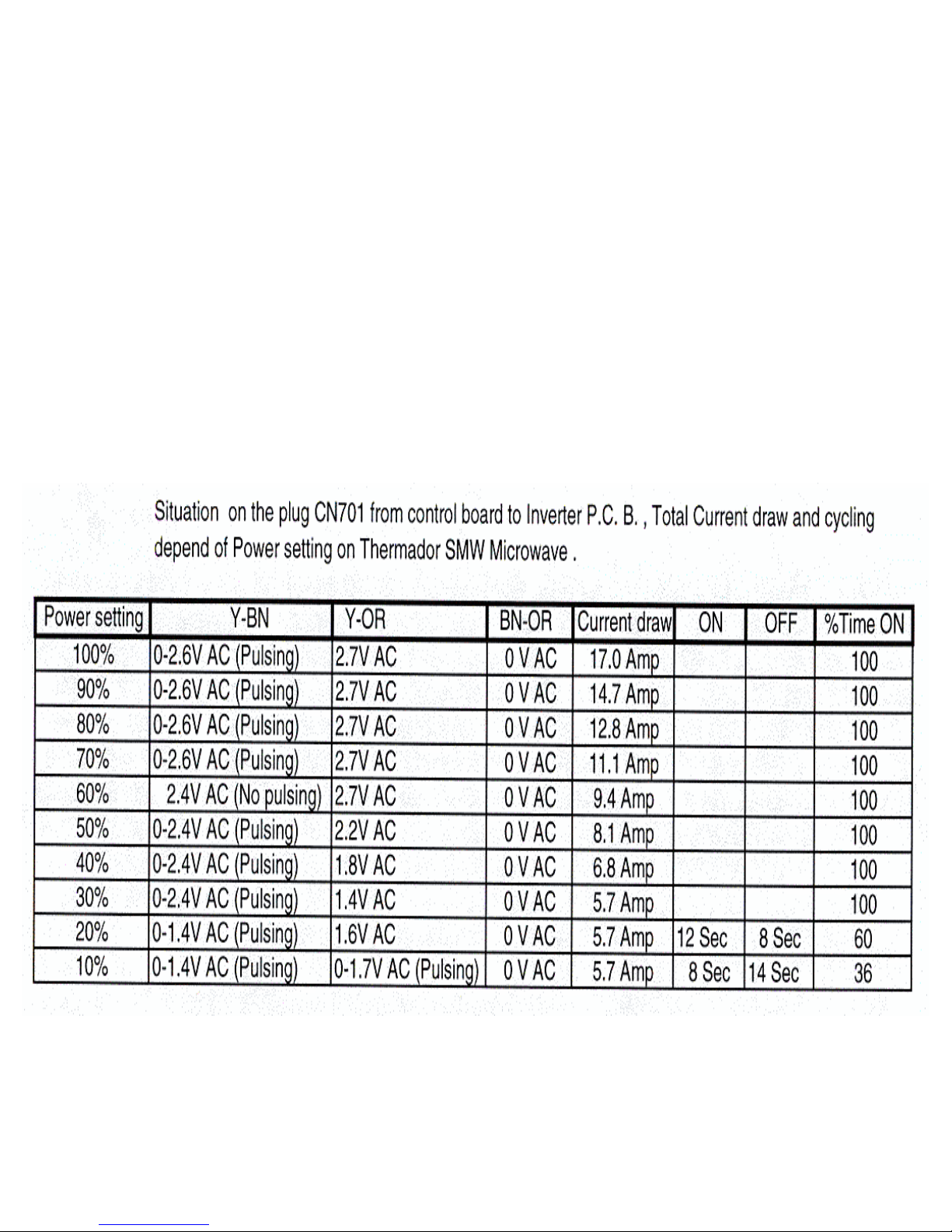
Low Voltage Input from DPC 0-2.7
Low Voltage Input from DPC 0-2.7
VAC ( see table on page 30)
VAC ( see table on page 30)
120 VAC Input
120 VAC Input
High Voltage 4000 VDC
High Voltage 4000 VDC
Output to
Output to
Mag
Mag
Tube
Tube
Note Do not attempt to repair this inverter
Note Do not attempt to repair this inverter
board. Replace as a complete assembly
board. Replace as a complete assembly
Page 30
30
30
Variable Power & Voltage readings from
Variable Power & Voltage readings from
DPC plug CN3
DPC plug CN3
Page 31
31
31
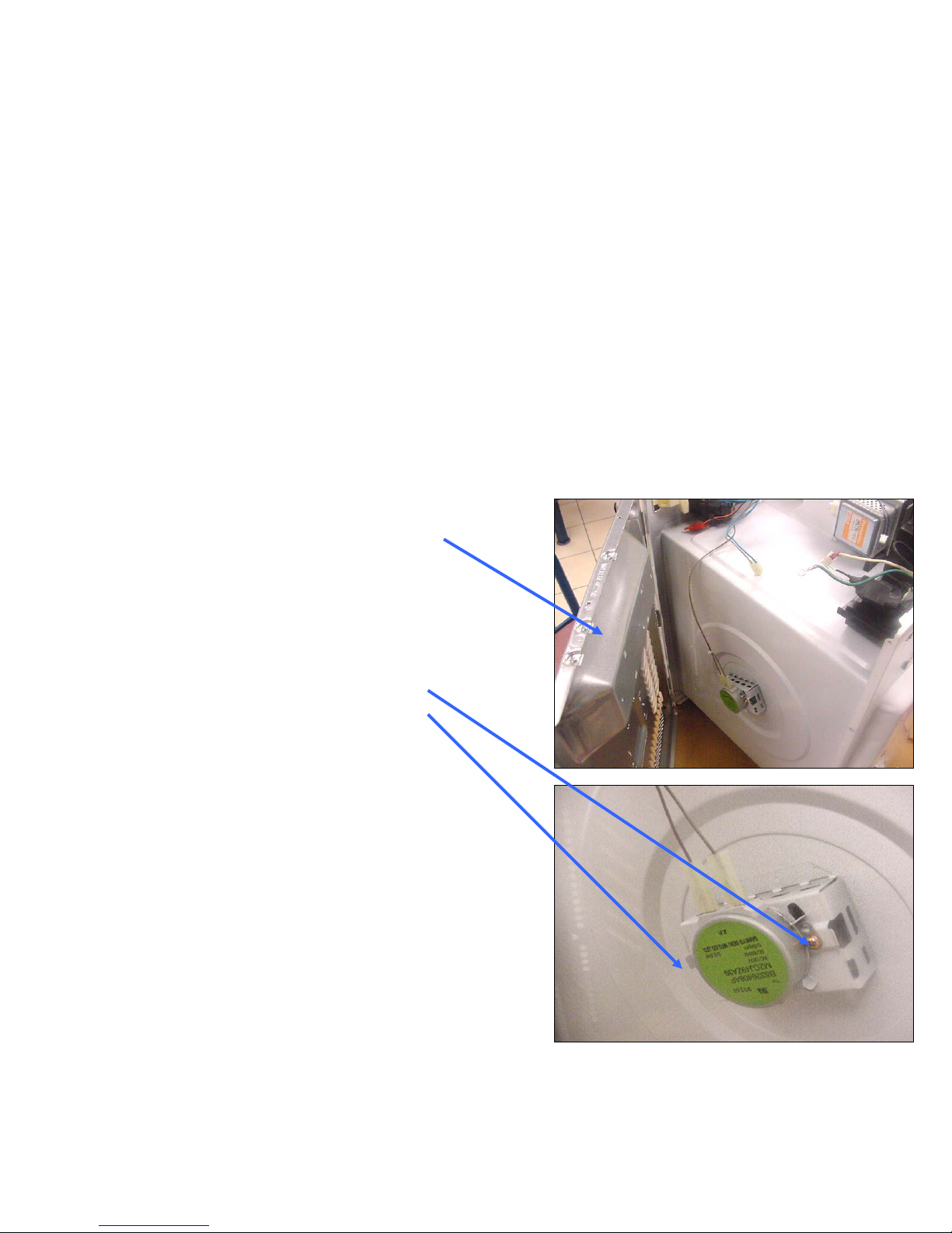
Component Description & Access…..
Stirrer Motor
Component Description &
Component Description &
Access…..
Access…..
Stirrer Motor
Stirrer Motor
ä
ä
Remove base of unit or
Remove base of unit or
break off access cover and
break off access cover and
re-secure with screws
re-secure with screws
ä
ä
Stirrer motor is held in
Stirrer motor is held in
place with two screws
place with two screws
ä
ä
Motor is a synchronous
Motor is a synchronous
type with a ‘D’ shaft and
type with a ‘D’ shaft and
operates off of 120VAC.
operates off of 120VAC.
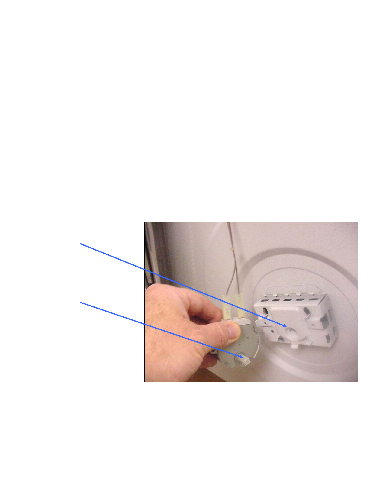
When replacing the motor
When replacing the motor
ensure that the shaft locates
ensure that the shaft locates
into bearing insert.
into bearing insert.
31
31
Page 32
32
32
Component Description & Access….
Stirrer Motor
Component Description &
Component Description &
Access….
Access….
Stirrer Motor
Stirrer Motor
ä
ä
‘D’ Slot
‘D’ Slot
ä
ä
‘D’ Shaft
‘D’ Shaft
Page 33
33
33
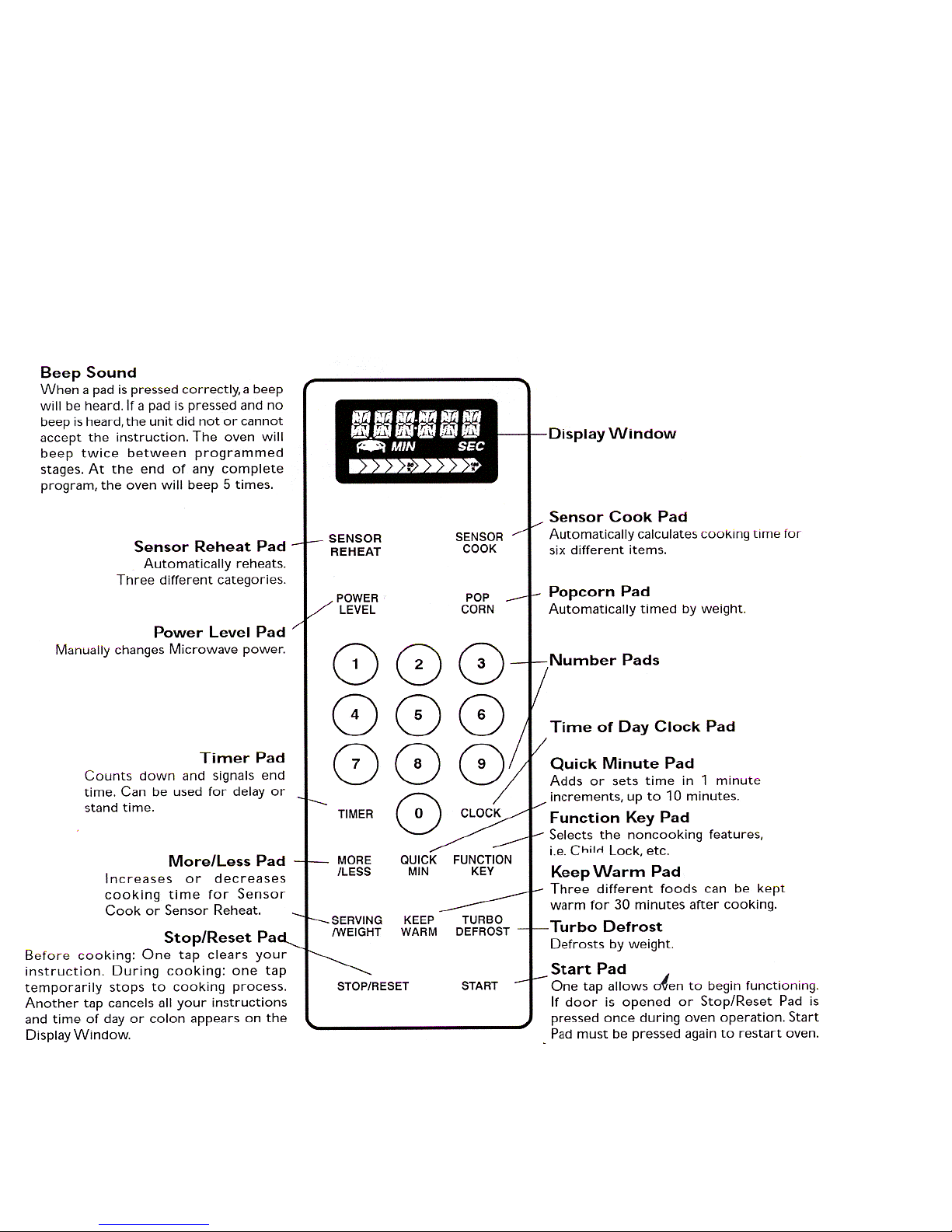
Microwave
Microwave
Control Panel
Control Panel
Page 34
34
34
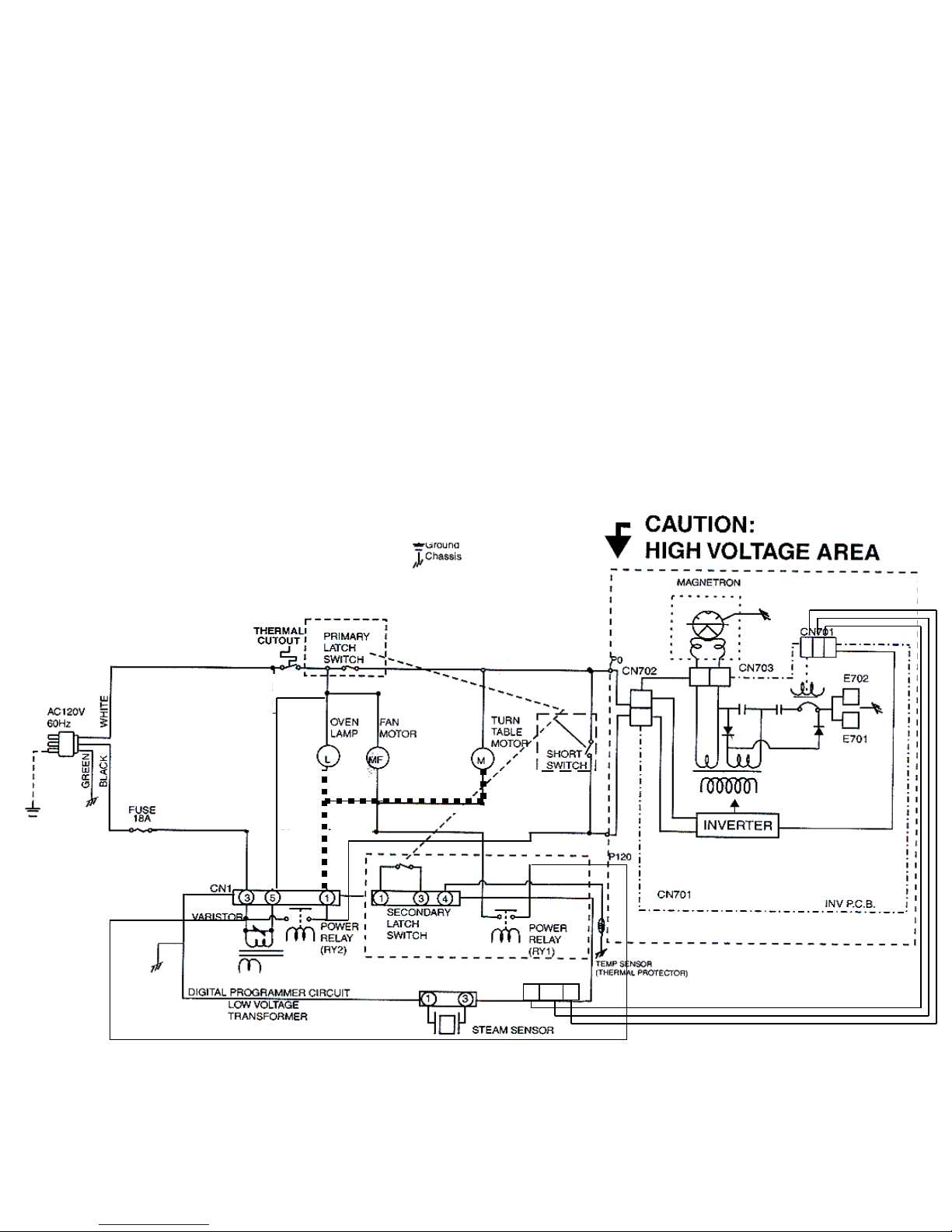
SMW How the Oven works…Microwave section
SMW How the Oven works…Microwave section
CN2
CN2
CN4
CN4
CN3
CN3
33221
1
11223
3
Low Voltage Supply
Low Voltage Supply
controls variable power
controls variable power
Microwave door closed, short switch is open, primary
Microwave door closed, short switch is open, primary
and secondary latch switches are closed. Unit is not
and secondary latch switches are closed. Unit is not
operating.
operating.
34
34
A
A
B
B
Note the oven lamp and
Note the oven lamp and
turntable motor circuits are
turntable motor circuits are
powered up when door is
powered up when door is
opened, however only the
opened, however only the
lamp has a neutral return
lamp has a neutral return
Orange
Orange
Red
Red
Brown
Brown
Page 35
35
35
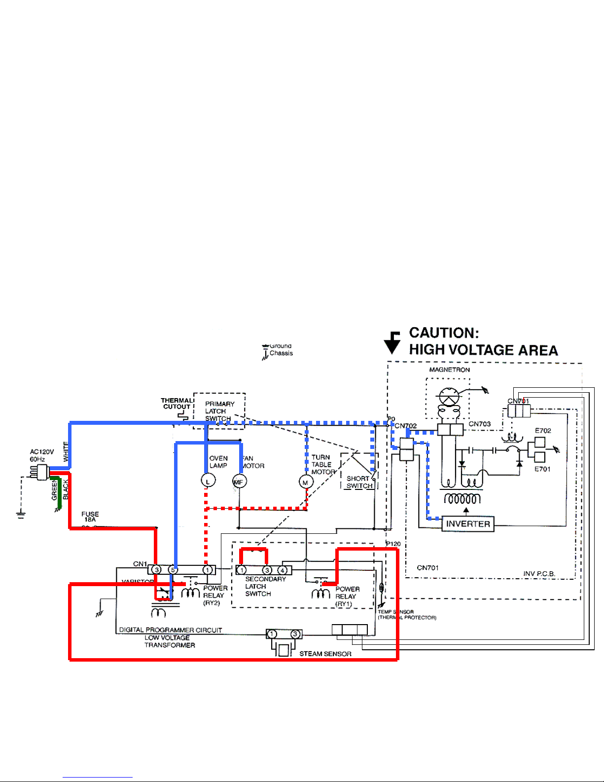
SMW How the Oven works…Microwave section
SMW How the Oven works…Microwave section
CN2
CN2
CN4
CN4
CN3
CN3
33221
1
11223
3
Low Voltage Supply
Low Voltage Supply
controls variable power
controls variable power
Microwave door closed, short switch is open, primary
Microwave door closed, short switch is open, primary
and secondary latch switches are closed. Unit is not
and secondary latch switches are closed. Unit is not
operating.
operating.
35
35
A
A
B
B
Note the oven lamp and
Note the oven lamp and
turntable motor circuits are
turntable motor circuits are
powered up when door is
powered up when door is
opened, however only the
opened, however only the
lamp has a neutral return
lamp has a neutral return
Red
Red
Orange
Orange
Brown
Brown
Page 36
36
36
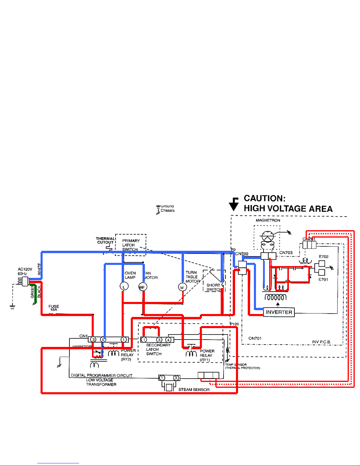
SMW How the Oven works…Microwave section
SMW How the Oven works…Microwave section
CN2
CN2
CN4
CN4
CN3
CN3
33221
1
11223
3
Low Voltage Supply
Low Voltage Supply
controls variable power
controls variable power
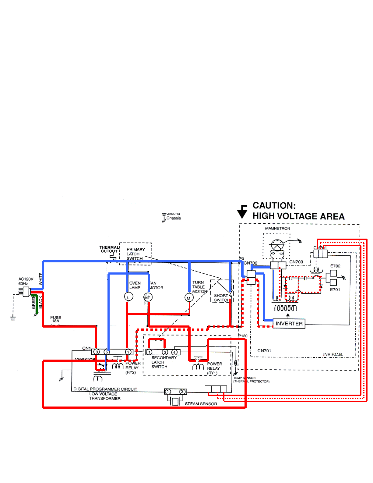
Microwave on high, power relay coil ‘B’ is energized
Microwave on high, power relay coil ‘B’ is energized
constantly during each 22 second cycle while calling
constantly during each 22 second cycle while calling
for heat
for heat
36
36
A
A
B
B
Red
Red
Orange
Orange
Brown
Brown
Page 37
37
37
SMW How the Oven works…Microwave section
SMW How the Oven works…Microwave section
CN2
CN2
CN4
CN4
CN3
CN3
33221
1
11223
3
Low Voltage Supply
Low Voltage Supply
controls variable power
controls variable power
Microwave on, 20% power level, relay coil ‘B’ is energized 15
Microwave on, 20% power level, relay coil ‘B’ is energized 15
seconds on and 7 seconds off out of each 22 second cycle
seconds on and 7 seconds off out of each 22 second cycle
while calling for heat
while calling for heat
37
37
A
A
B
B
Red
Red
Orange
Orange
Brown
Brown
Page 38
38
38
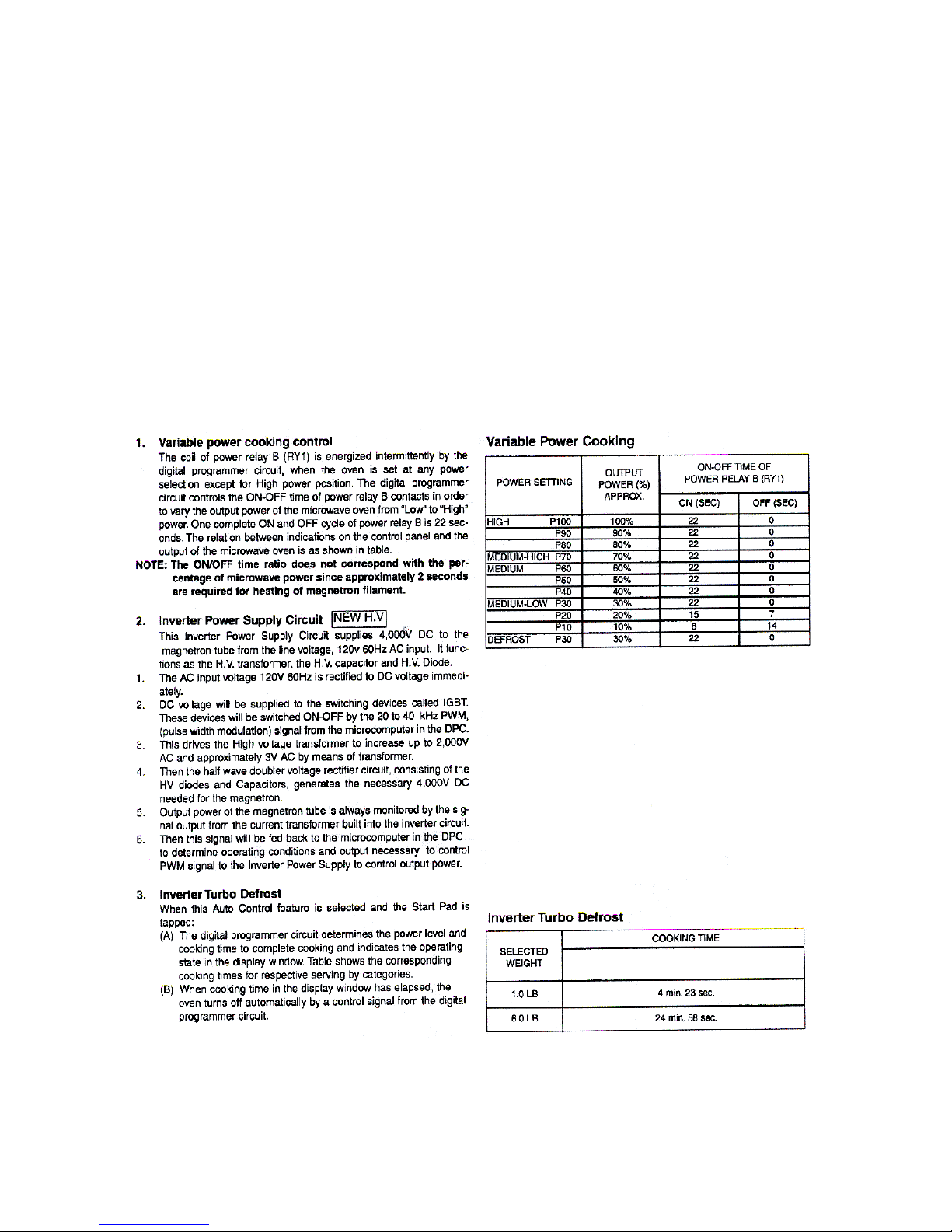
Description of Operating Sequence
Description of Operating Sequence
Page 39
39
39
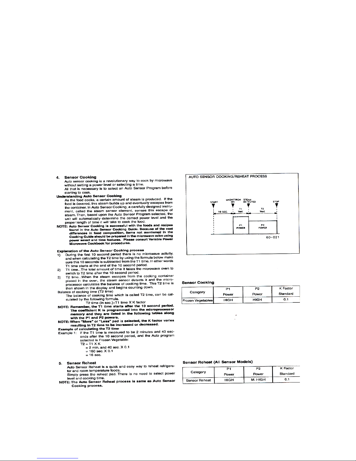
Description of Operating Sequence….
Description of Operating Sequence….
Sensor
Sensor
Cooking & Sensor Reheat
Cooking & Sensor Reheat
Page 40
40
40
Page 41
41
41
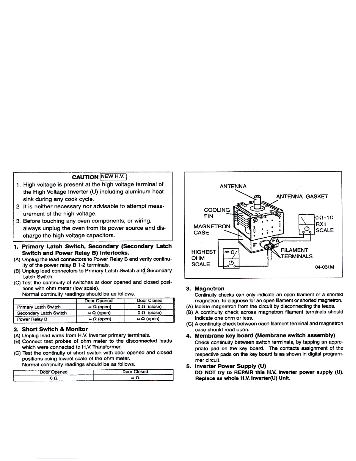
Microwave Section…..Component Test Procedures
Microwave Section…..Component Test Procedures
41
41
Page 42
42
42
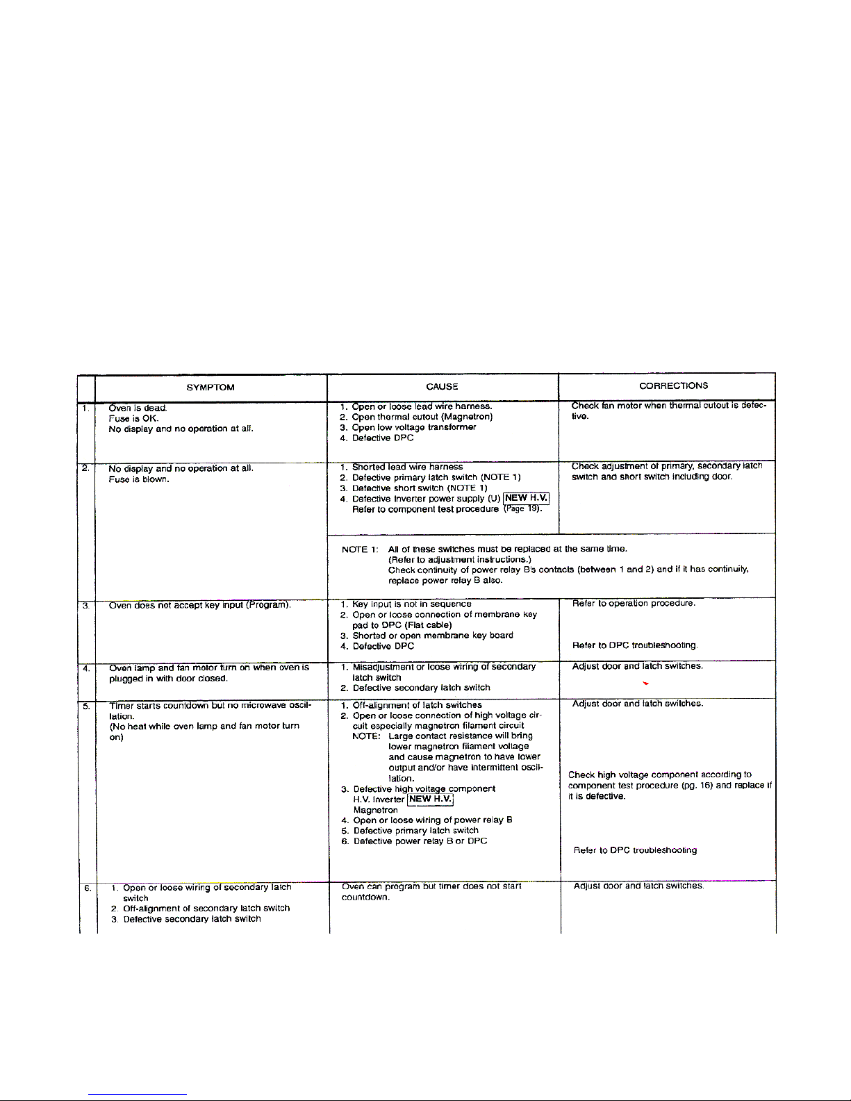
Troubleshooting Guide
Troubleshooting Guide
Page 43
43
43
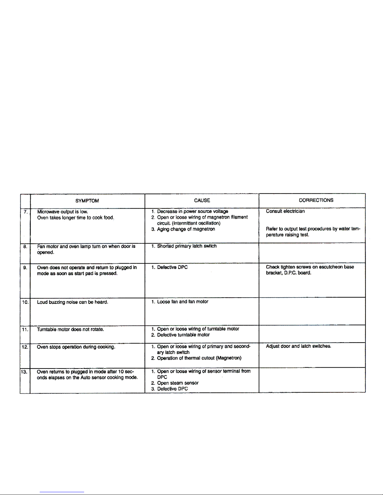
Troubleshooting Guide…..continued
Troubleshooting Guide…..continued
Page 44
44
44
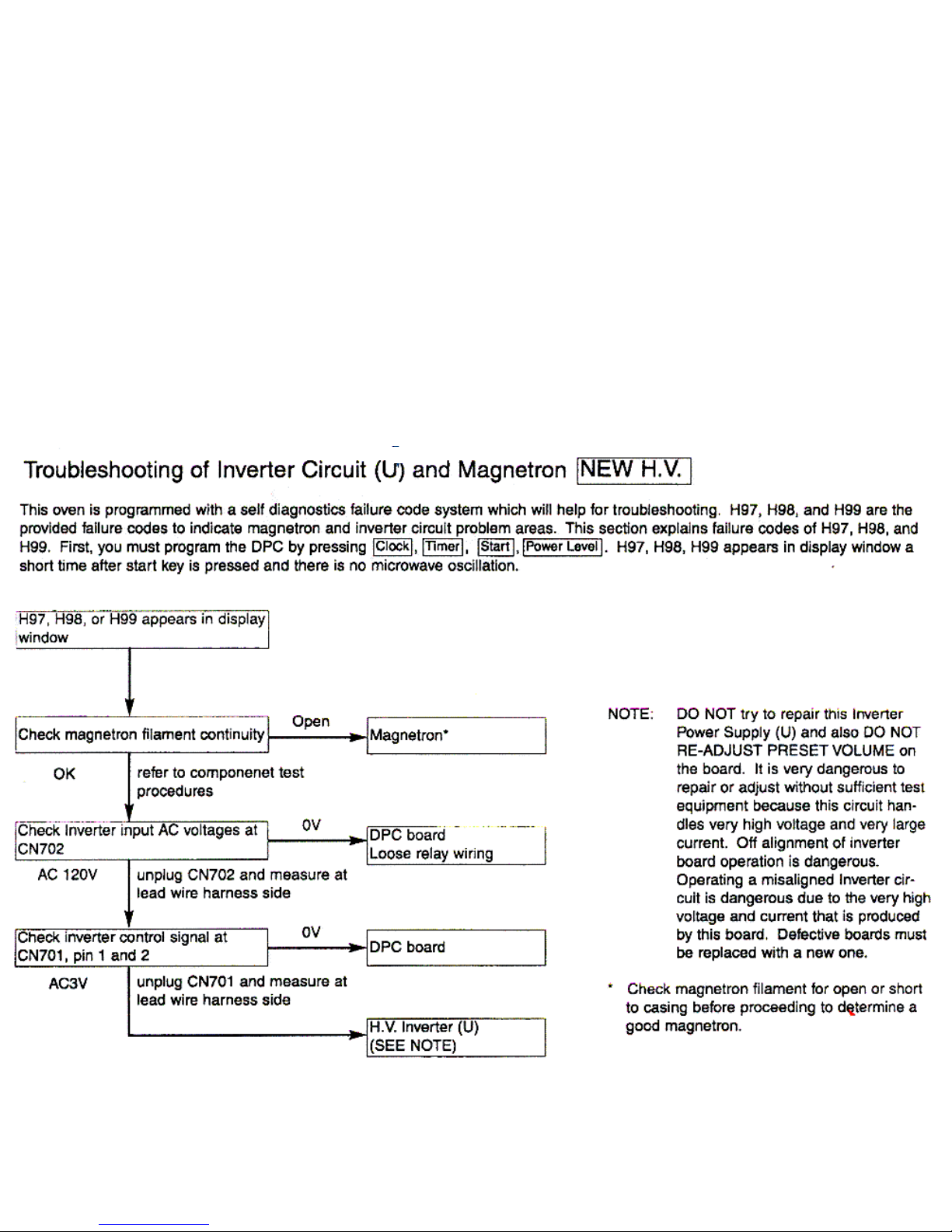
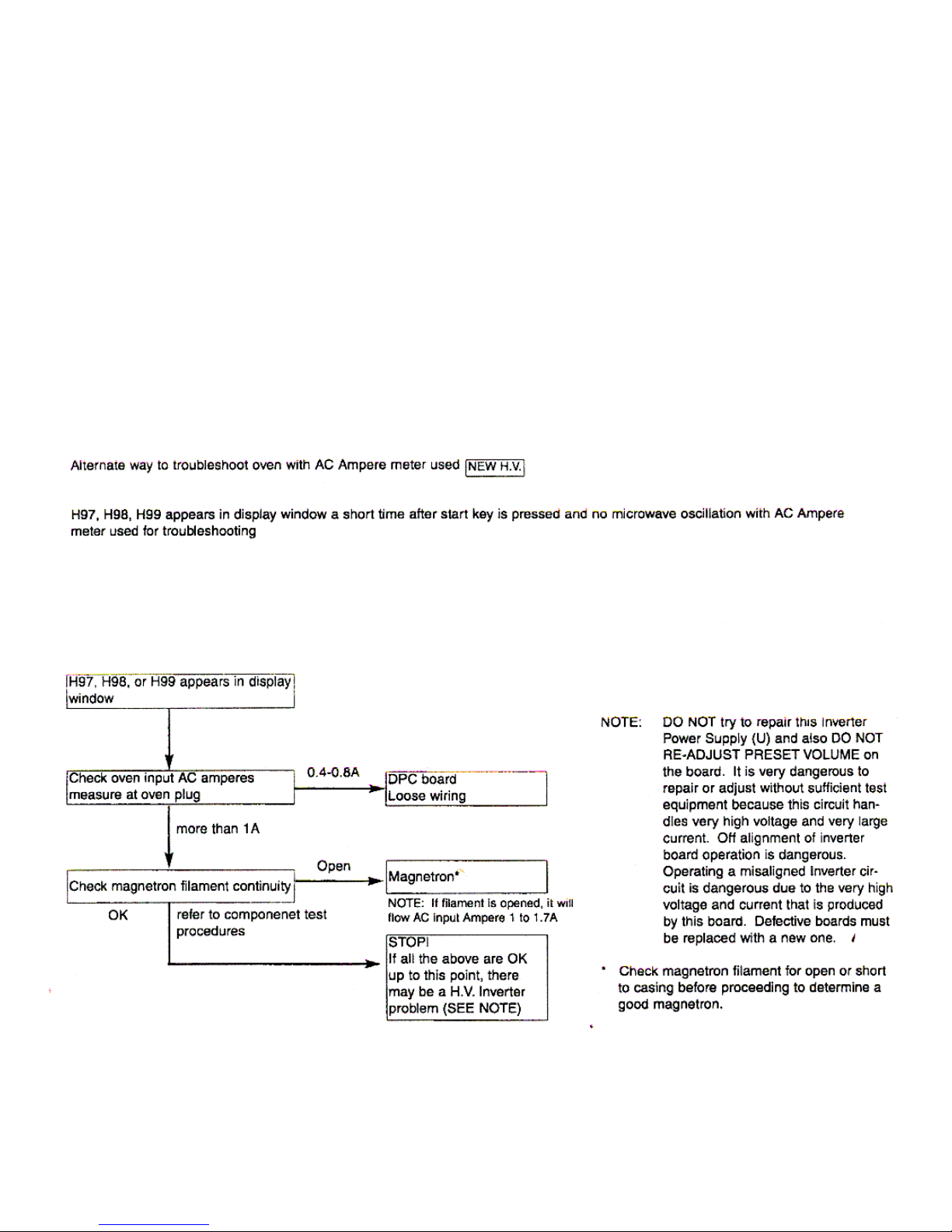
Microwave Section Troubleshooting HV Inverter
Microwave Section Troubleshooting HV Inverter
44
44
Page 45
45
45
45
45
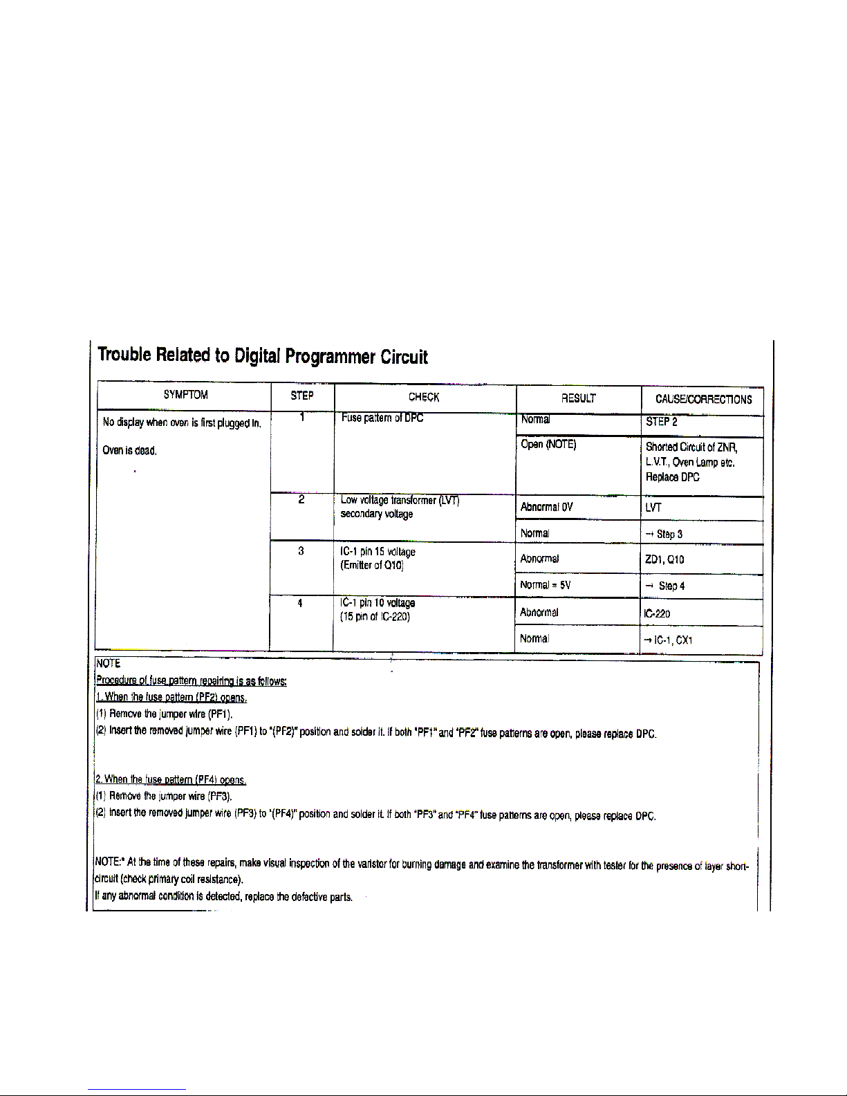
Troubleshooting HV Inverter…continued
Troubleshooting HV Inverter…continued
Page 46
46
46
Page 47
47
47
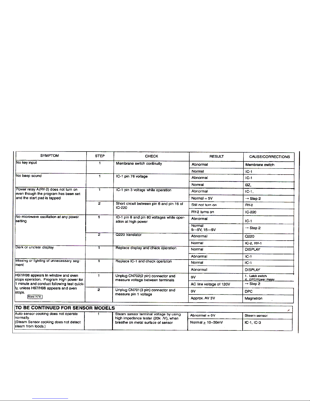
Trouble Related to Digital Programmer Circuit….continued
Trouble Related to Digital Programmer Circuit….continued
Page 48
48
48
Page 49
49
49
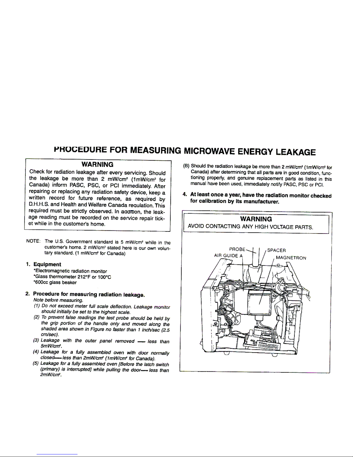
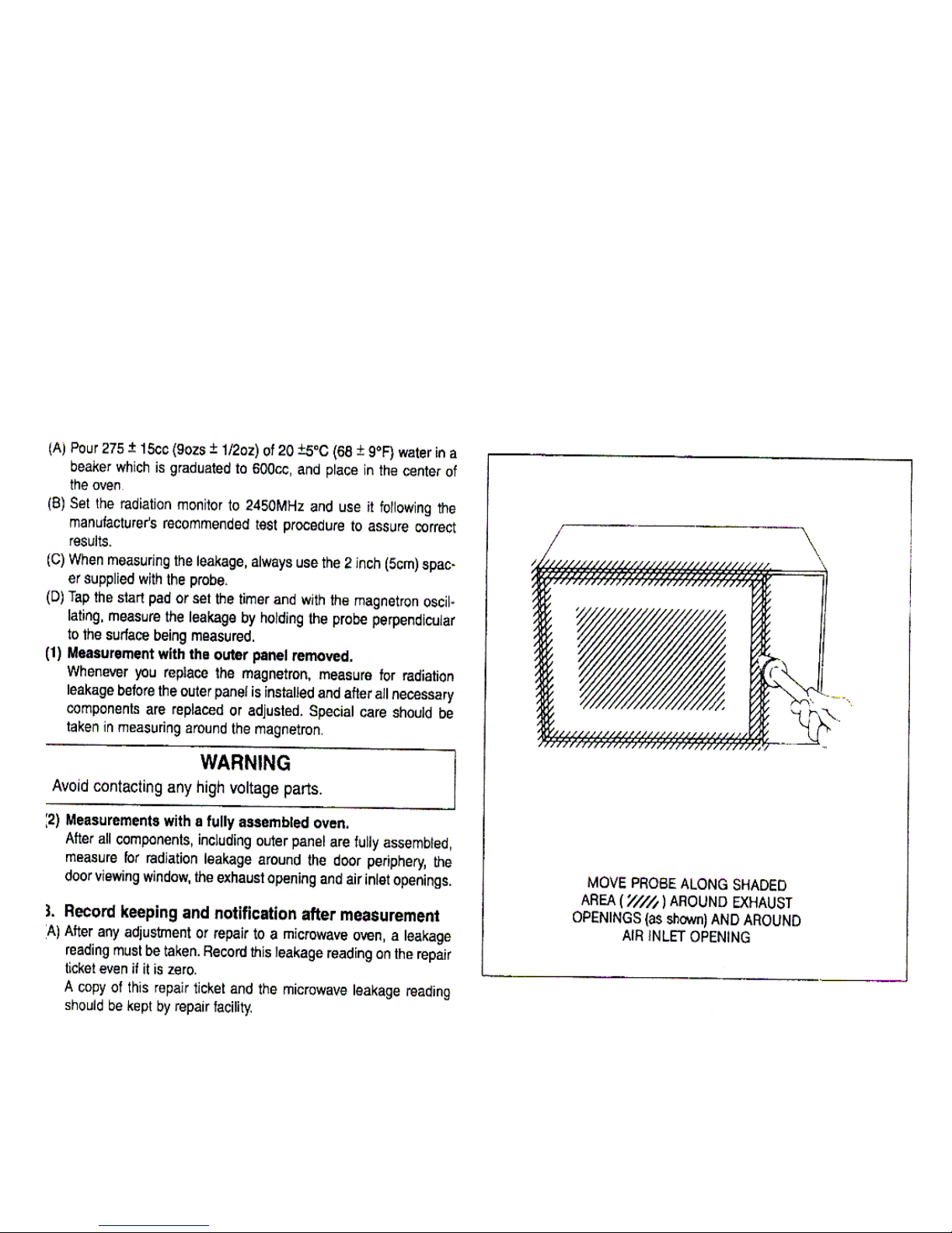
Microwave Leakage Test….continued
Microwave Leakage Test….continued
Page 50
50
50
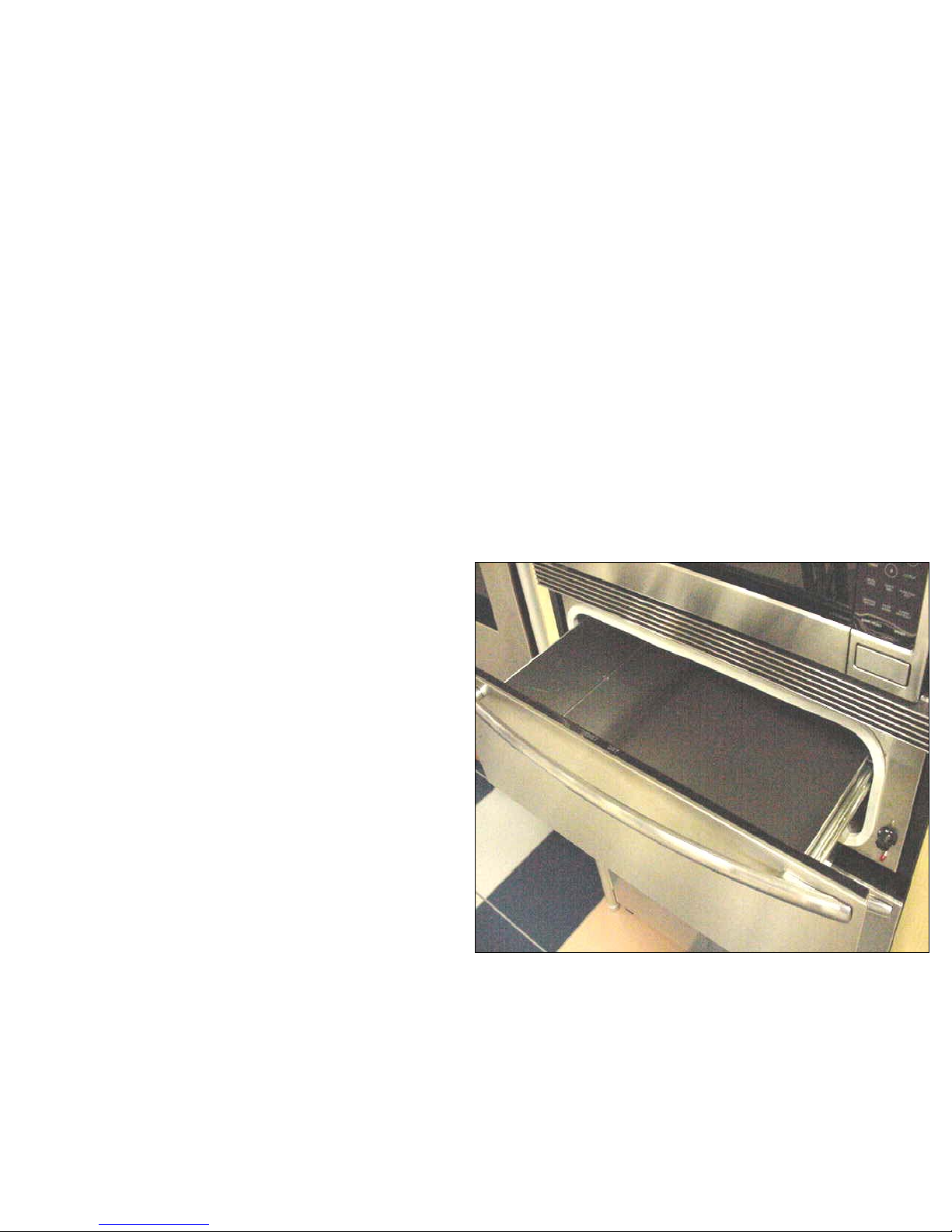
Warming Drawer Section….
Warming Drawer Section….
Features &
Features &
Benefits
Benefits
••
On Indicator Light
On Indicator Light
can be
can be
viewed through drawer front
viewed through drawer front
•• 450 Watt
450 Watt
Element
Element
••
On/Off
On/Off
Switch
Switch
••
Thermostat
Thermostat
has low, medium
has low, medium
& high settings. 140, 170, and
& high settings. 140, 170, and
210 degrees F
210 degrees F
••
Easy glide
Easy glide
drawer slides
drawer slides
Page 51
51
51
Component Description &
Component Description &
Access
Access
…
…
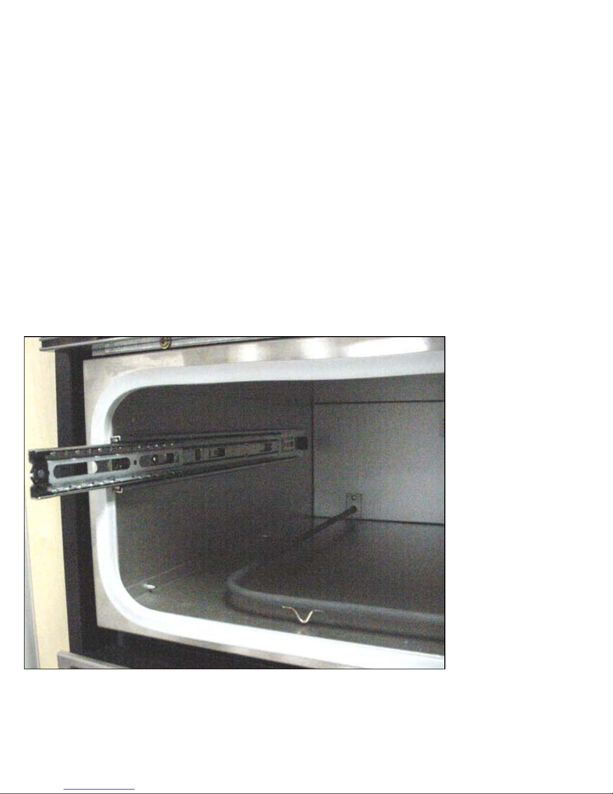
Element & Slides
Element & Slides
Slides are
Slides are
held in
held in
place with
place with
two screws
two screws
Page 52
52
52
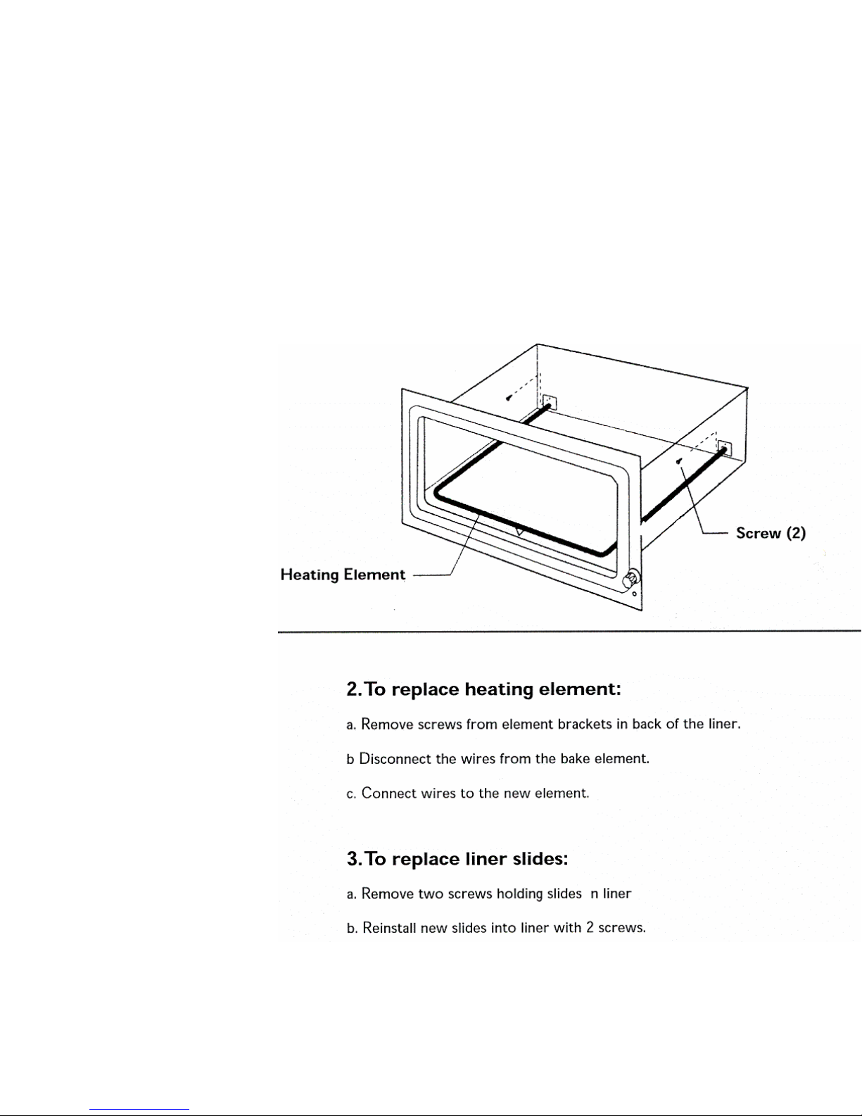
Component
Component
Description &
Description &
Access….Element
Access….Element
& Slides
& Slides
52
52
Page 53
53
53
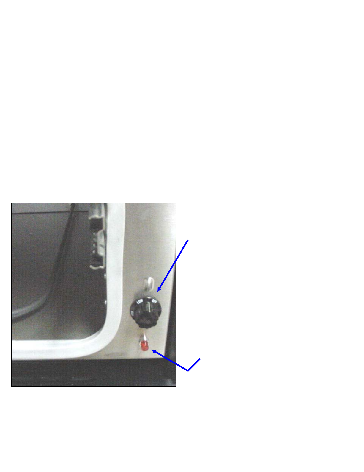
Component Description &
Component Description &
Access
Access
…Thermostat & On light
…Thermostat & On light
Thermostat Control has three
Thermostat Control has three
settings….
settings….
Low..140 degrees F
Low..140 degrees F
Medium…170 degrees F
Medium…170 degrees F
High…210 degrees F
High…210 degrees F
Indicator light remains
Indicator light remains
illuminated the whole time the
illuminated the whole time the
unit is turned on, it does not
unit is turned on, it does not
turn on and off with the cycles
turn on and off with the cycles
of the thermostat
of the thermostat
Page 54
54
54
Component Description & Access...
Component Description & Access...
Thermostat Switch and on lamp
Thermostat Switch and on lamp
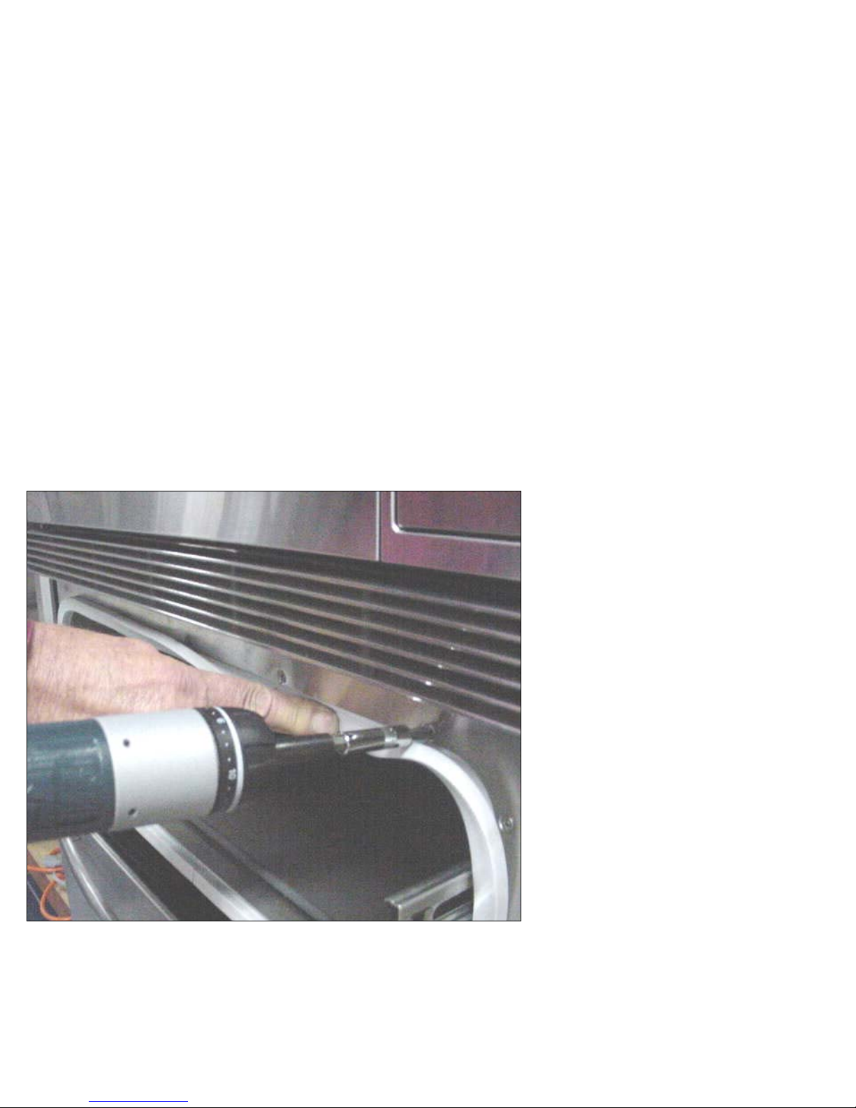
To access controls
To access controls
front frame of
front frame of
warming drawer has
warming drawer has
to be removed. Peel
to be removed. Peel
back drawer gasket
back drawer gasket
and remove the 14
and remove the 14
countersunk Phillips
countersunk Phillips
screws. Pull off
screws. Pull off
thermostat knob and
thermostat knob and
remove frame
remove frame
Page 55
55
55
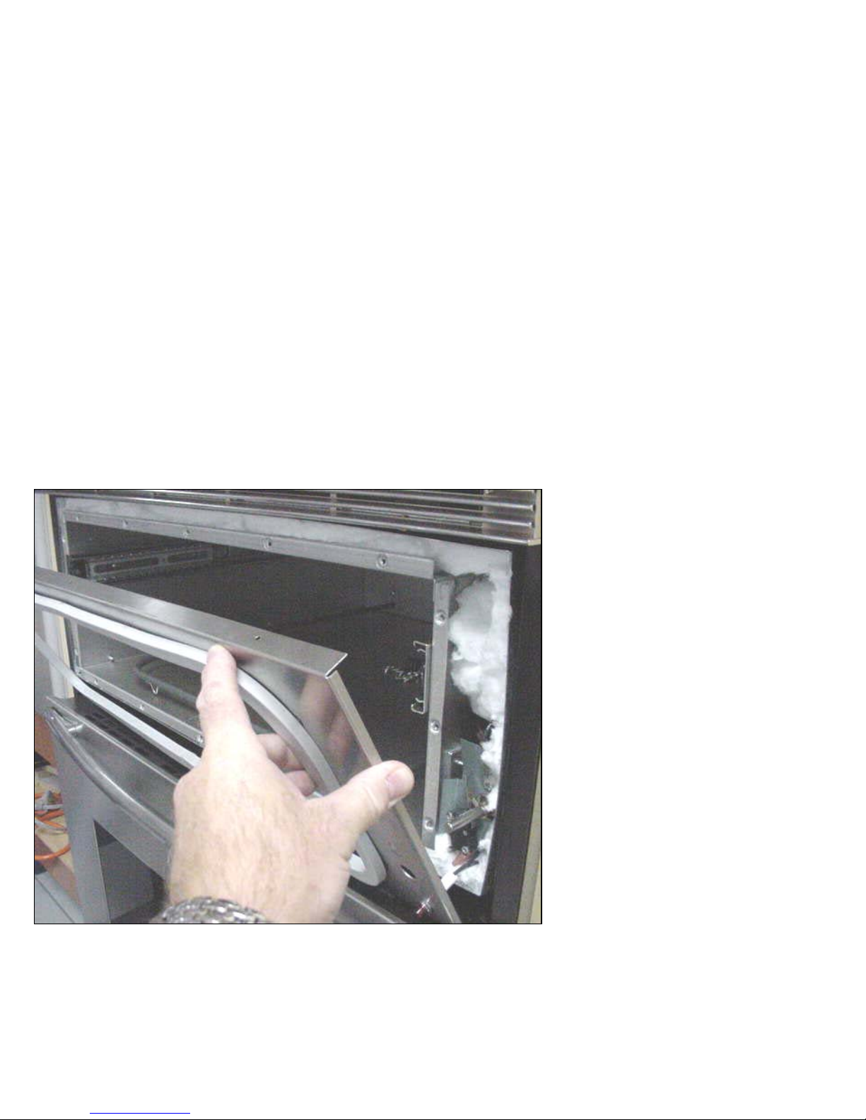
Thermostat,
Thermostat,
switch, and the
switch, and the
‘on’ indicator
‘on’ indicator
light can now be
light can now be
accessed from
accessed from
right side of unit
right side of unit
This procedure is
This procedure is
also necessary to
also necessary to
replace drawer
replace drawer
gasket
gasket
Component Description &
Component Description &
Access….
Access….
Thermostat switch on lamp & gasket
Thermostat switch on lamp & gasket
Page 56
56
56
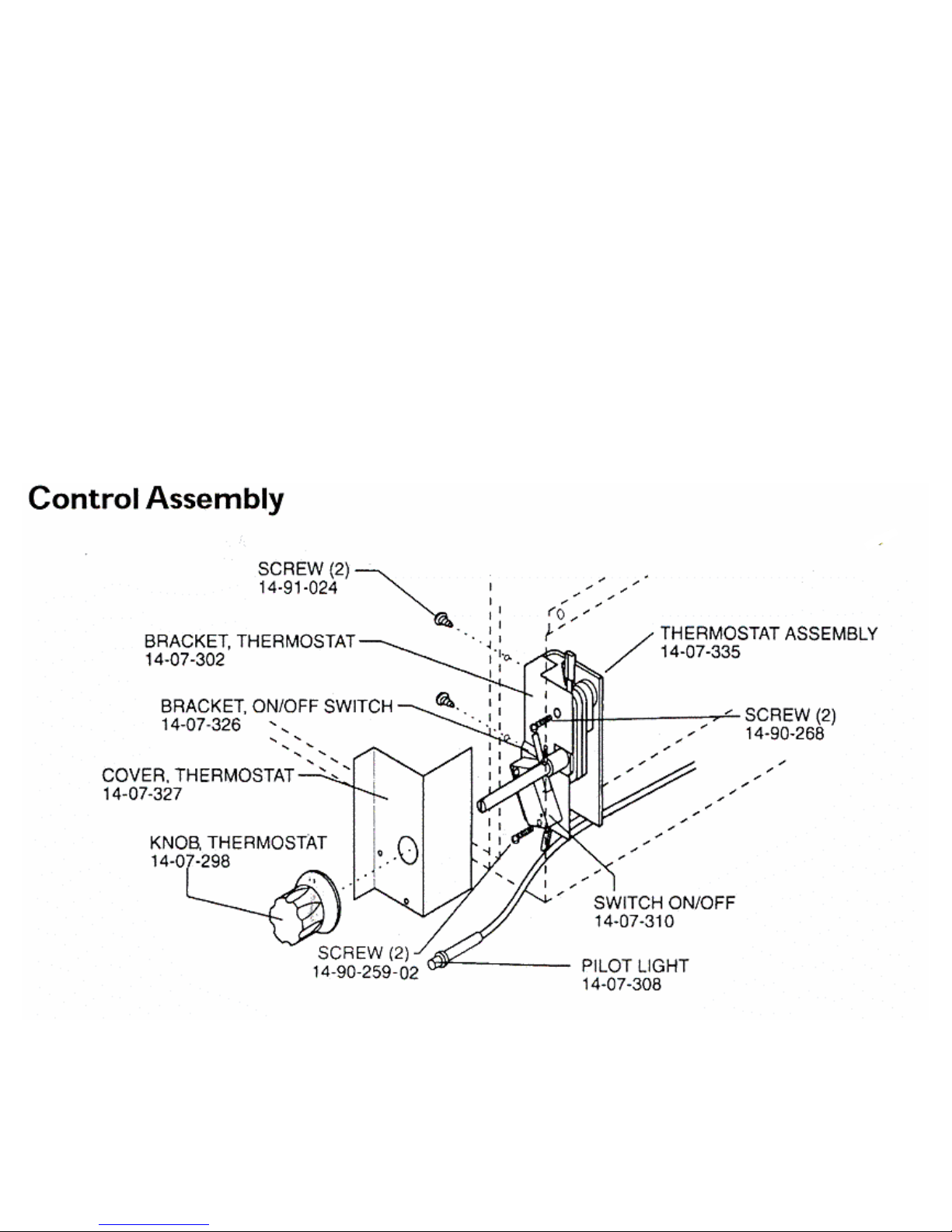
Component Description &
Component Description &
Access Switch & Thermostat
Access Switch & Thermostat
Page 57
57
57
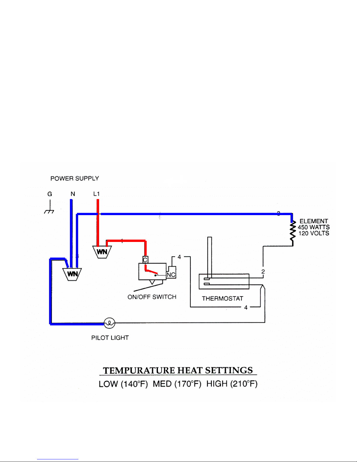
How the Oven works….
How the Oven works….
Warming Drawer
Warming Drawer
57
57
Unit in the off position
Unit in the off position
3.75 amps
3.75 amps
Page 58
58
58
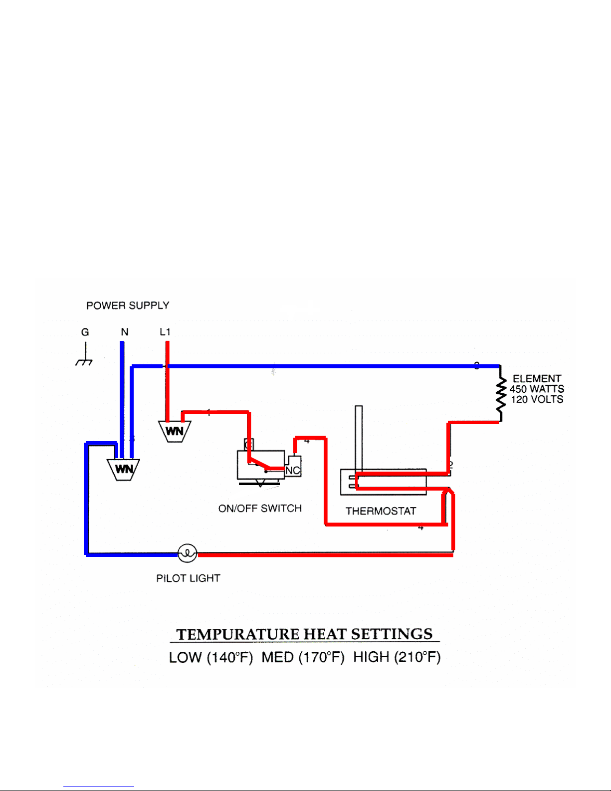
How the Oven works….
How the Oven works….
Warming Drawer
Warming Drawer
58
58
Unit in the on position,
Unit in the on position,
thermostat contacts
thermostat contacts
cycling
cycling
3.75 amps
3.75 amps
Page 59

59
59
Lower Oven Features
Lower Oven Features
Lower Oven Features
ä
ä
“Field Sensor” touch control
“Field Sensor” touch control
ä
ä
Digi
Digi
-pad numeric control panel
-pad numeric control panel
ä
ä
Centigrade or Fahrenheit temperature
Centigrade or Fahrenheit temperature
display
display
ä
ä
A 12 or 24 hour clock
A 12 or 24 hour clock
ä
ä
Child lock-out feature
Child lock-out feature
ä
ä
Bread proofing and Dehydration modes
Bread proofing and Dehydration modes
ä
ä
Large viewing door window
Large viewing door window
Page 60

60
60
Features
Features
Features
ä
ä
Third Element Convection
Third Element Convection
ä
ä
Convection Roast mode
Convection Roast mode
ä
ä
Recessed 8 wrap broil element
Recessed 8 wrap broil element
ä
ä
Internal ventilation system
Internal ventilation system
ä
ä
End of cycle chime
End of cycle chime
ä
ä
To restore: Touch Upper oven “OFF” pad
To restore: Touch Upper oven “OFF” pad
for 10 seconds, until you hear the chime
for 10 seconds, until you hear the chime
Page 61

61
61
…..and Operation
…..and Operation
…..and Operation
ä
ä
Window Display
Window Display
ä
ä
Cook Time
Cook Time
ä
ä
Timer 1
Timer 1
ä
ä
Clock
Clock
ä
ä
Stop Time
Stop Time
ä
ä
Timer 2
Timer 2
ä
ä
Oven Light
Oven Light
ä
ä
Number Pads
Number Pads
ä
ä
Bake
Bake
ä
ä
Broil
Broil
ä
ä
Convection
Convection
ä
ä
Off
Off
ä
ä
Self Clean
Self Clean
ä
ä
Convection Roast
Convection Roast
Page 62

62
62
…..and Operation Test Mode
…..and Operation
…..and Operation
Test Mode
Test Mode
ä
ä
Electronic oven control test mode
Electronic oven control test mode
ä
ä
Power up unit
Power up unit
ä
ä
Do the following within 5 minutes, before
Do the following within 5 minutes, before
any other programming
any other programming
ä
ä
Hold the STOP TIME pad key for 10
Hold the STOP TIME pad key for 10
seconds
seconds
ä
ä
Unit will enter test mode
Unit will enter test mode
ä
ä
Test the function key pads
Test the function key pads
Page 63

63
63
…..and Operation Calibration
…..and Operation
…..and Operation
Calibration
Calibration
ä
ä
Oven Temperature Calibration
Oven Temperature Calibration
ä
ä
Touch BAKE pad
Touch BAKE pad
ä
ä
Set Temperature between 500 and 550
Set Temperature between 500 and 550
ä
ä
Hold BAKE pad for 4 seconds
Hold BAKE pad for 4 seconds
ä
ä
0 or last calibrated Temperature will display
0 or last calibrated Temperature will display
ä
ä
Touch BROIL pad to toggle between + and -
Touch BROIL pad to toggle between + and -
ä
ä
From zero + or - 35 degrees calibration
From zero + or - 35 degrees calibration
possible
possible
Page 64

64
64
Component Description
Component Description
Component Description
ä
ä
Lower Oven Relay
Lower Oven Relay
Board
Board
ä
ä
Control Panel
Control Panel
ä
ä
Display Head
Display Head
ä
ä
Sensor
Sensor
ä
ä
Halogen Light
Halogen Light
ä
ä
Halogen Light
Halogen Light
Transformer
Transformer
ä
ä
Cooling Fans
Cooling Fans
Page 65
65
65
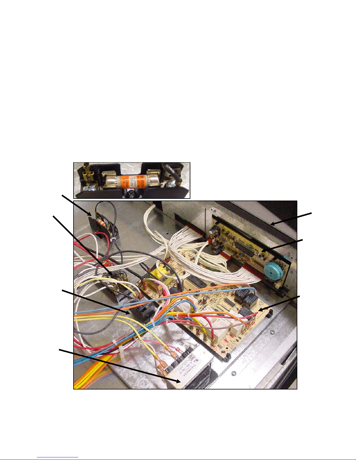
Component Description & Access….Plenum
Components
Component Description & Access….
Component Description & Access….
Plenum
Plenum
Components
Components
Time delay fuse
Time delay fuse
rated at 20amp
rated at 20amp
Terminal Block
Terminal Block
Stalled Fan Relay
Stalled Fan Relay
coil is energized
coil is energized
by 120volts AC
by 120volts AC
from air switch.
from air switch.
Contacts transfer
Contacts transfer
120VAC from HTC
120VAC from HTC
to DLB relay on
to DLB relay on
board (K8)
board (K8)
Halogen Light
Halogen Light
Transformer.
Transformer.
Primary
Primary
Input120VAC
Input120VAC
Secondary Output
Secondary Output
12VAC
12VAC
Control Panel
Control Panel
Display Head
Display Head
(Clock)
(Clock)
Relay Board
Relay Board
Page 66
66
66
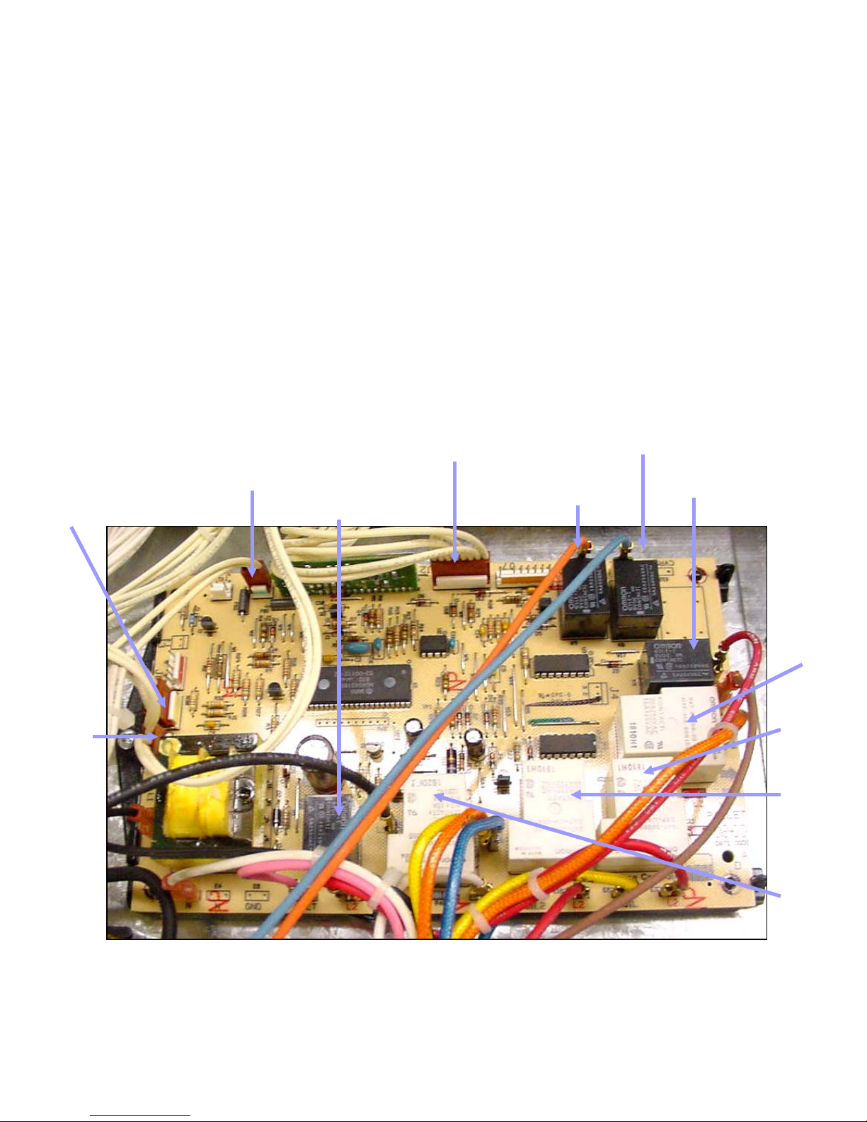
Component Description…Relay Board
Component Description…
Component Description…
Relay Board
Relay Board
(Part # 16-10-660)
(Part # 16-10-660)
K6 Cooling
K6 Cooling
Motor Relay
Motor Relay
K9 Latch Motor
K9 Latch Motor
Relay
Relay
K4 Convection
K4 Convection
Motor Relay
Motor Relay
K1 Bake
K1 Bake
Element
Element
Relay
Relay
K2 Broil
K2 Broil
Element
Element
Relay
Relay
K3
K3
Convection
Convection
Element
Element
Relay
Relay
K8 Double
K8 Double
Line Break
Line Break
Relay
Relay
J2 Pin Connector Transfers data
J2 Pin Connector Transfers data
between board, touch panel &
between board, touch panel &
display head
display head
K7 Light
K7 Light
Relay Powers
Relay Powers
Light
Light
Transformer
Transformer
J10 Pin
J10 Pin
Connector
Connector
Transfers
Transfers
signal voltage
signal voltage
to sensor
to sensor
J5 Pin
J5 Pin
Connector
Connector
Transfers signal
Transfers signal
voltage through
voltage through
the latch
the latch
switches
switches
J1 Pin
J1 Pin
Connector
Connector
Power Supply
Power Supply
from the
from the
board to the
board to the
display head
display head
20 VAC to
20 VAC to
illuminate it
illuminate it
and 12 VDC
and 12 VDC
logic power
logic power
Page 67
67
67
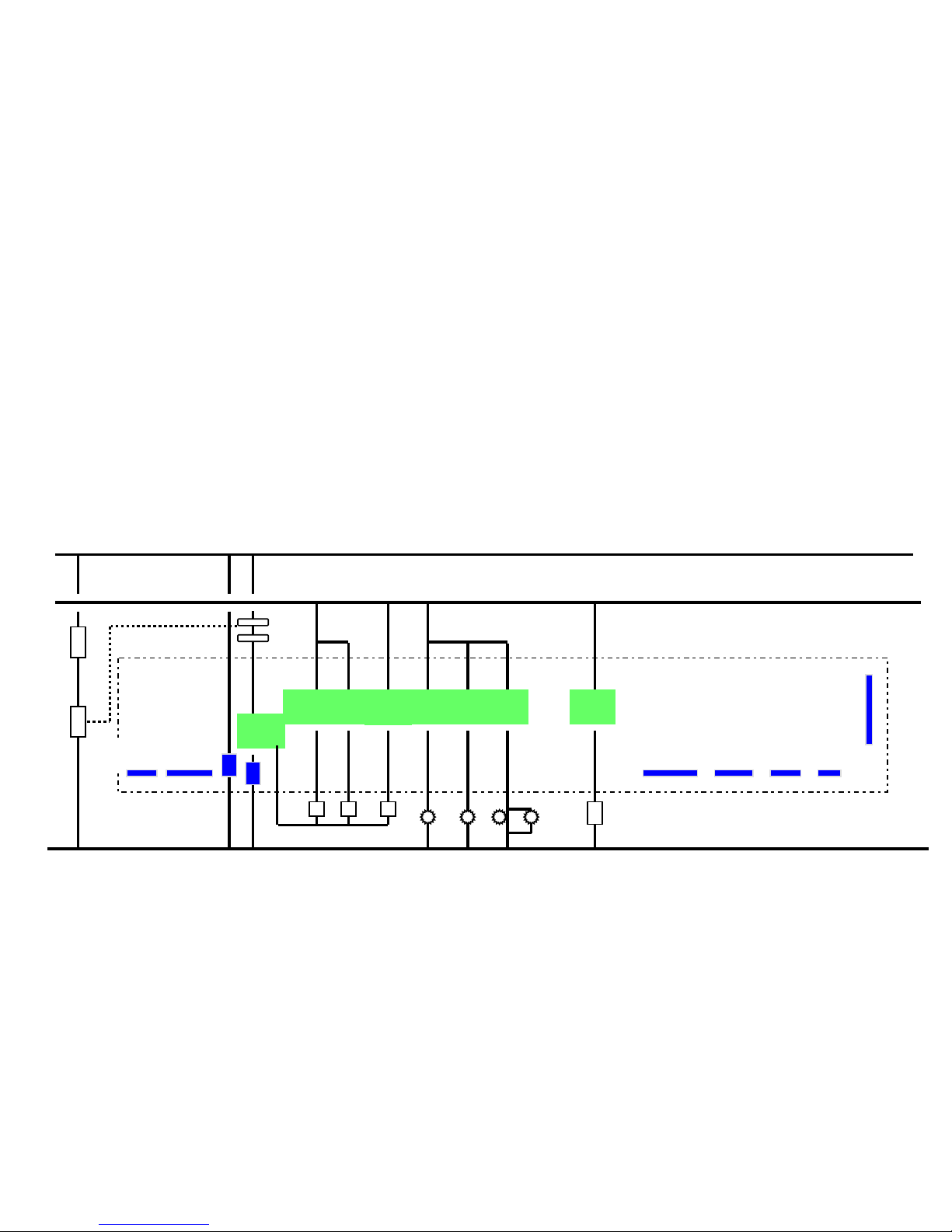
Component Description
Lower Oven Relay Board….Relays
Component Description
Component Description
Lower Oven Relay Board….Relays
Lower Oven Relay Board….Relays
K8…Line Break
K8…Line Break
K4…Convection Motor
K4…Convection Motor
K1…Bake Element
K1…Bake Element
K9…Latch Motor
K9…Latch Motor
K2…Broil Element
K2…Broil Element
K6…Cooling Motor
K6…Cooling Motor
K3…Convection Element K7…Light Transformer
K3…Convection Element K7…Light Transformer
K8
K8
K1K1K2
K2
K3
K3
K4K4K9K9K6
K6
K7
K7
J1J1J2
J2
J5
J5
J8J8J10
J10J9J9
J7
J7
L2
L2
N
N
L1
L1
Page 68
68
68
Component Description
Lower Oven Relay Board…Pin connectors
Component Description
Component Description
Lower Oven Relay Board…Pin connectors
Lower Oven Relay Board…Pin connectors
K8
K8
K1K1K2
K2
K3
K3
K4K4K9K9K6
K6
K7
K7
J1J1J2
J2
J5
J5
J8J8J10
J10J9J9
J7
J7
L2
L2
N
N
L1
L1
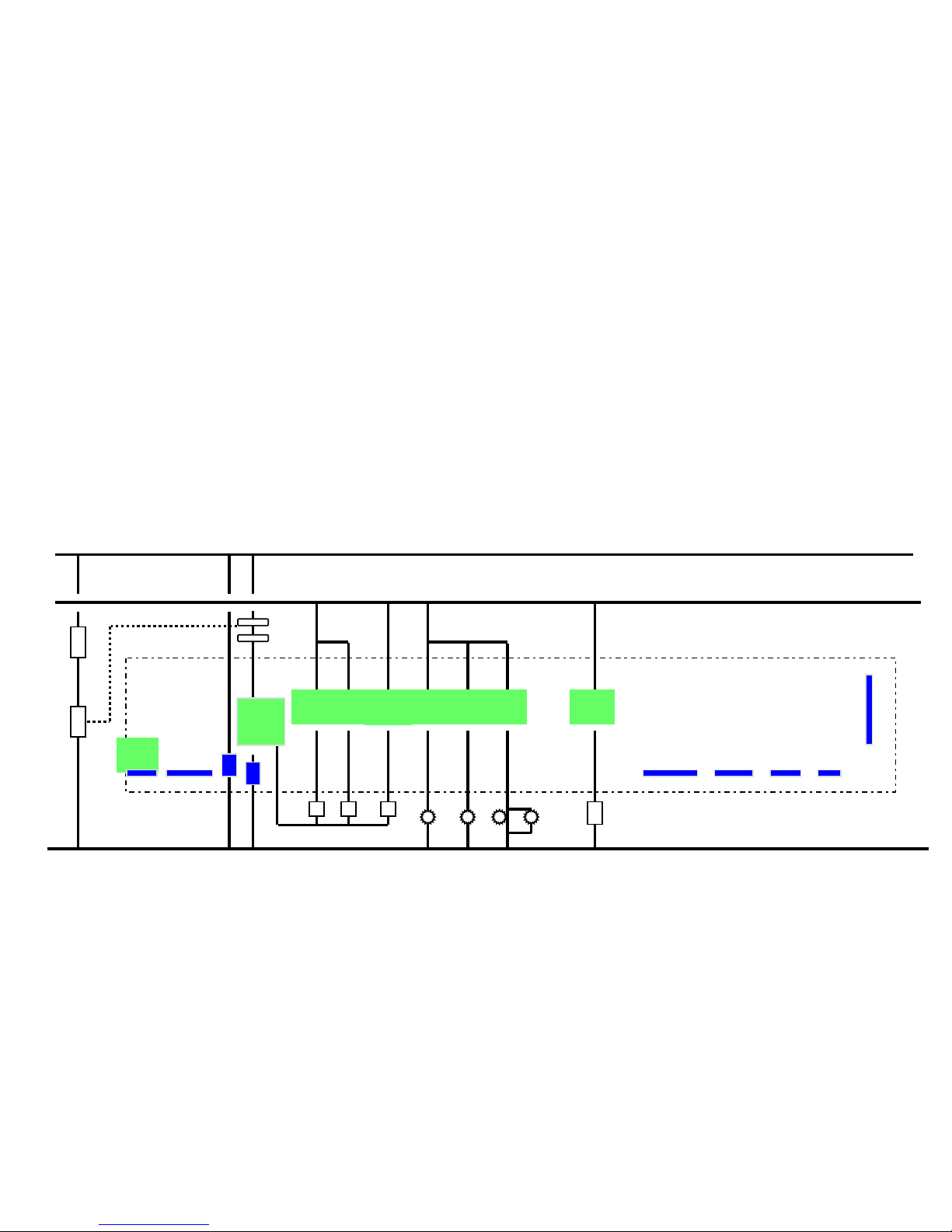
J1 is the power supply from the main relay board
J1 is the power supply from the main relay board
20 VAC to the display head to light it up (contacts 3-4)
20 VAC to the display head to light it up (contacts 3-4)
12 VDC for logic power to the touch board (contacts 1-2)
12 VDC for logic power to the touch board (contacts 1-2)
K8
K8
Page 69
69
69
Component Description
Lower Oven Relay Board…Pin connectors
Component Description
Component Description
Lower Oven Relay Board…Pin connectors
Lower Oven Relay Board…Pin connectors
K8
K8
K1K1K2
K2
K3
K3
K4K4K9K9K6
K6
K7
K7
J1J1J2
J2
J5
J5
J8J8J10
J10J9J9
J7
J7
L2
L2
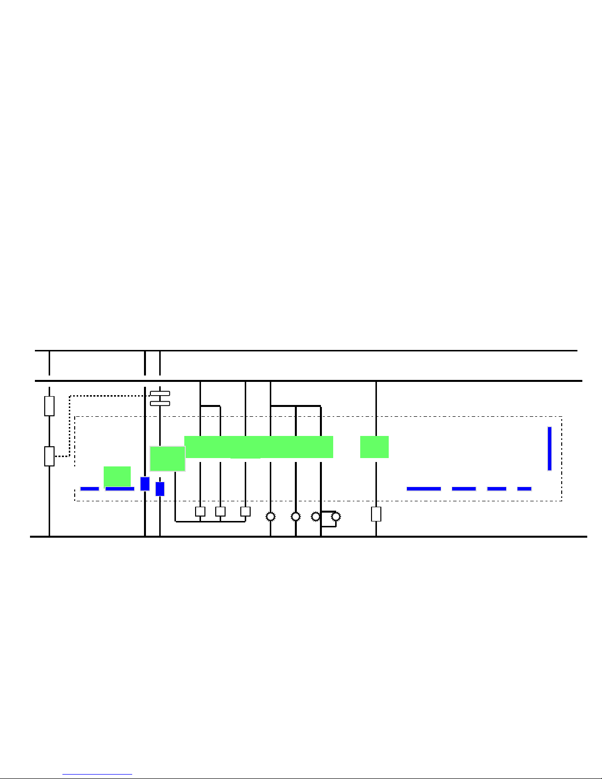
J2…transfers data between relay board, touch control
J2…transfers data between relay board, touch control
& display head
& display head
L1
L1
N
N
K8
K8
Page 70
70
70
Component Description….Lower Oven
Relay Board…Pin connectors
Component Description….
Component Description….
Lower
Lower
Oven
Oven
Relay Board…Pin connectors
Relay Board…Pin connectors
K8
K8
K1K1K2
K2
K3
K3
K4K4K9K9K6
K6
K7
K7
J1J1J2
J2
J5
J5
J8J8J10
J10J9J9
J7
J7
L2
L2
N
N
L1
L1
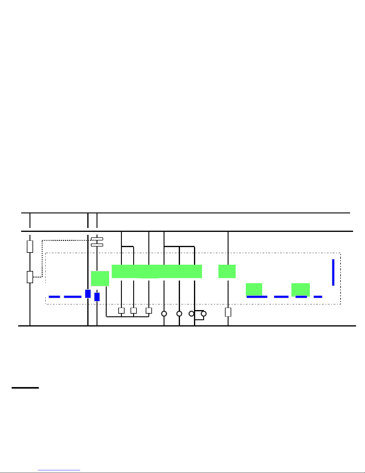
J5 … Transfers signal voltage through the latch switches
J5 … Transfers signal voltage through the latch switches
J10 …Transfers signal voltage to sensor
J10 …Transfers signal voltage to sensor
Note
Note
Since this is a single S oven pin connectors J7,J8 and J9
Since this is a single S oven pin connectors J7,J8 and J9
are not used
are not used
K8
K8
Page 71
71
71
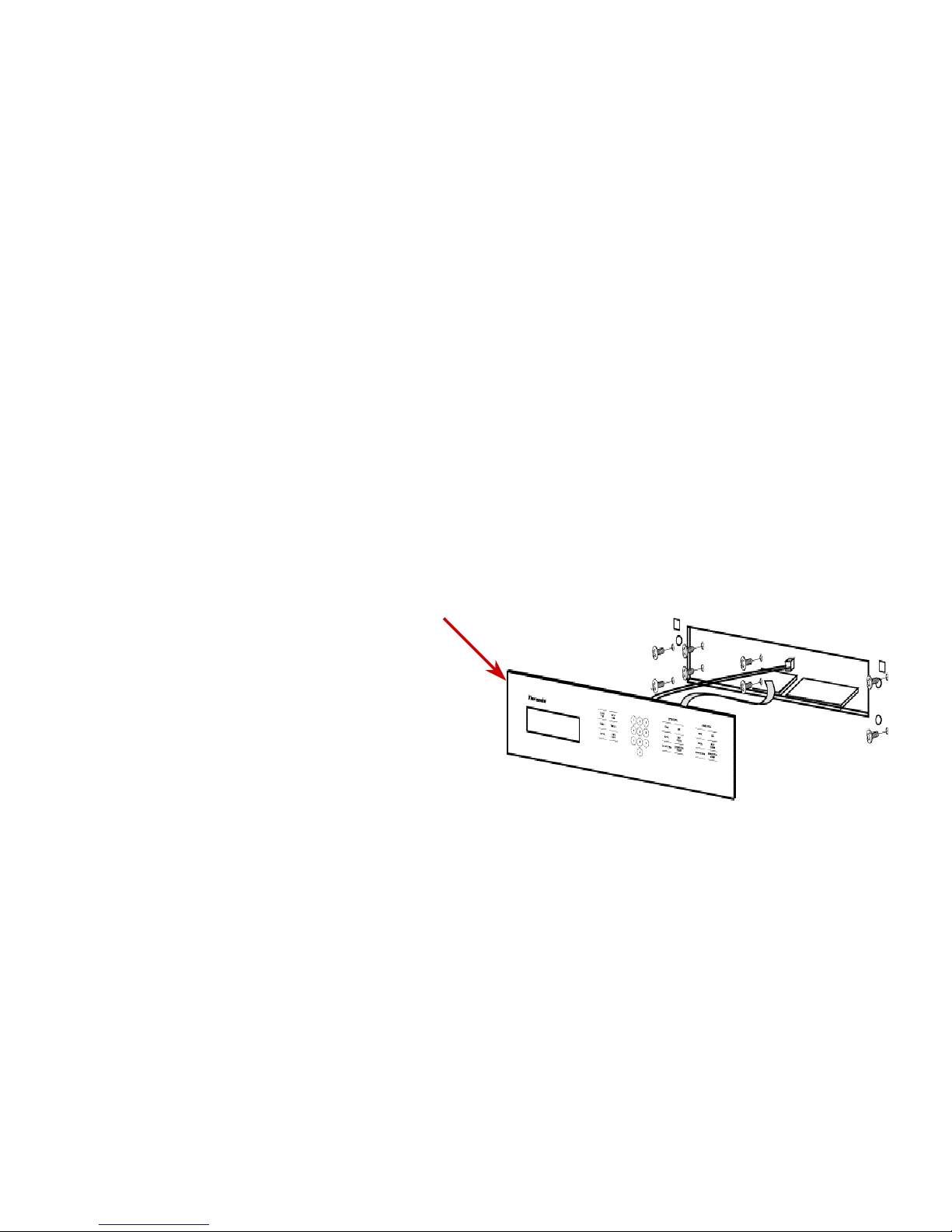
Component Description
Touch Control Panel
Component Description
Touch Control Panel
ä
ä
Contains 22 touch
Contains 22 touch
control pads
control pads
ä
ä
Touching the glass
Touching the glass
disturbs the
disturbs the
electromagnetic field
electromagnetic field
ä
ä
Touching the glass
Touching the glass
programs the oven
programs the oven
Page 72
72
72
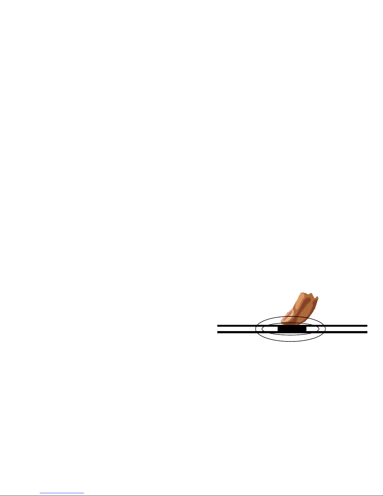
Touch Control Panel
Touch Control Panel
• Electromagnetic field
effect
• NOT membrane
• NOT capacitive
• 22 control pads
• Programmable
Page 73

73
73
Testing the touch control panel
Testing the touch control panel
ä
ä
Test points on touch control panel
Test points on touch control panel
ä
ä
One point is marked with a minus
One point is marked with a minus
ä
ä
Other point is marked with a plus
Other point is marked with a plus
ä
ä
Remove conforming coating on surface of
Remove conforming coating on surface of
pads
pads
ä
ä
Test for voltage between points
Test for voltage between points
ä
ä
0VDC when pad not being touched
0VDC when pad not being touched
ä
ä
5VDC when pad is being touched
5VDC when pad is being touched
Page 74
74
74
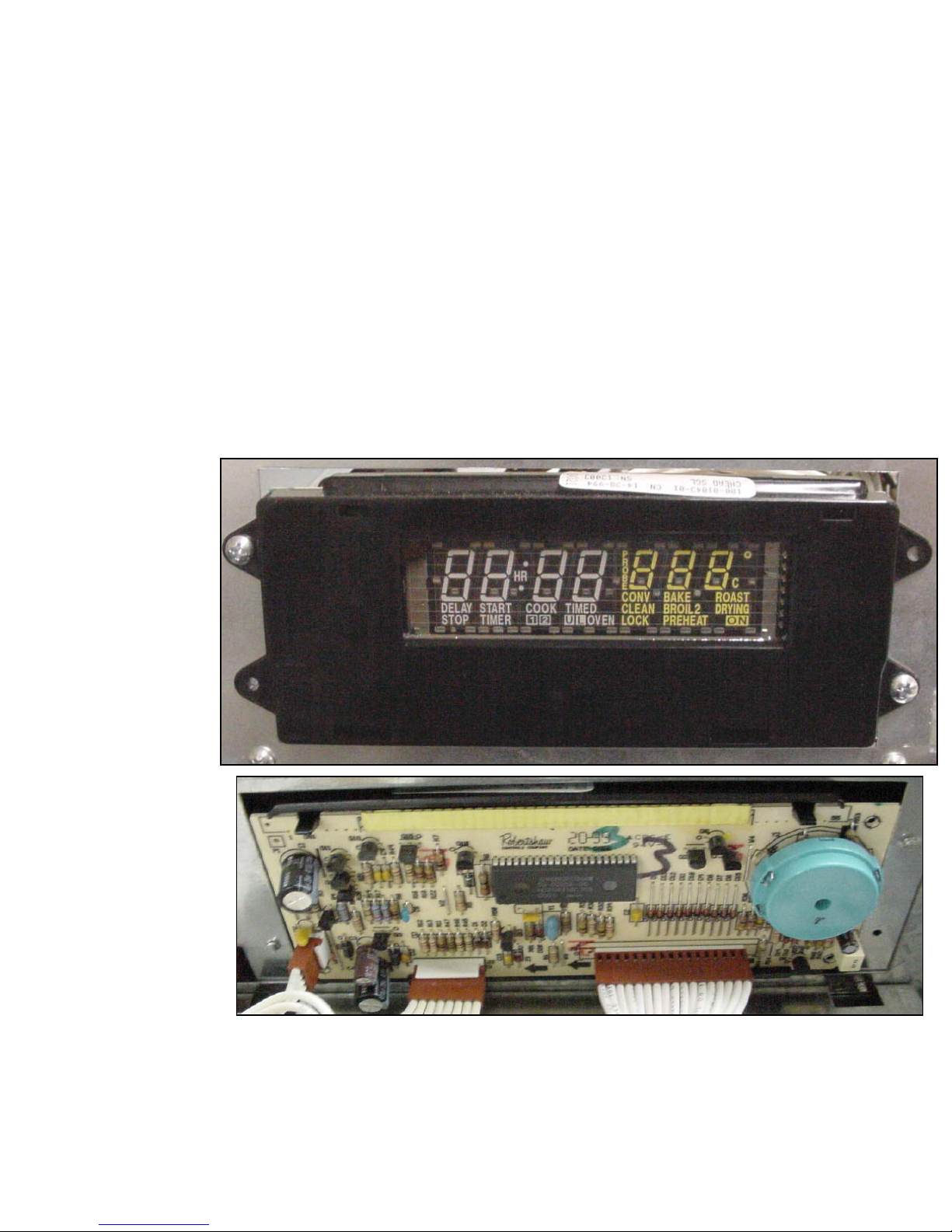
Component Description...Display Head
Component Description...Display Head
Displays
Displays
the
the
program
program
function
function
selected
selected
Page 75
75
75
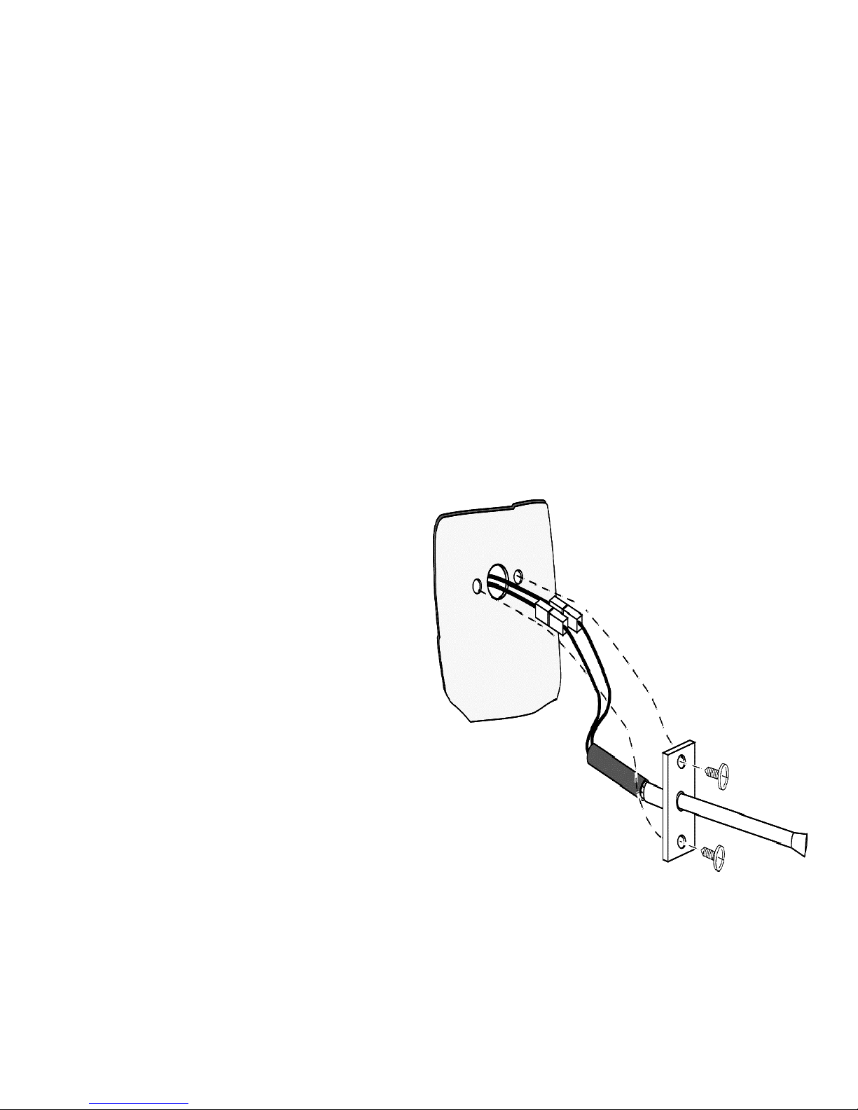
Component Description
Sensor
Component Description
Sensor
ä
ä
1050 OHMS at room
1050 OHMS at room
temperature
temperature
ä
ä
Ohm out leads at
Ohm out leads at
relay board
relay board
ä
ä
F3 = open sensor
F3 = open sensor
circuit
circuit
ä
ä
F4 = short in sensor
F4 = short in sensor
circuit
circuit
Page 76
76
76
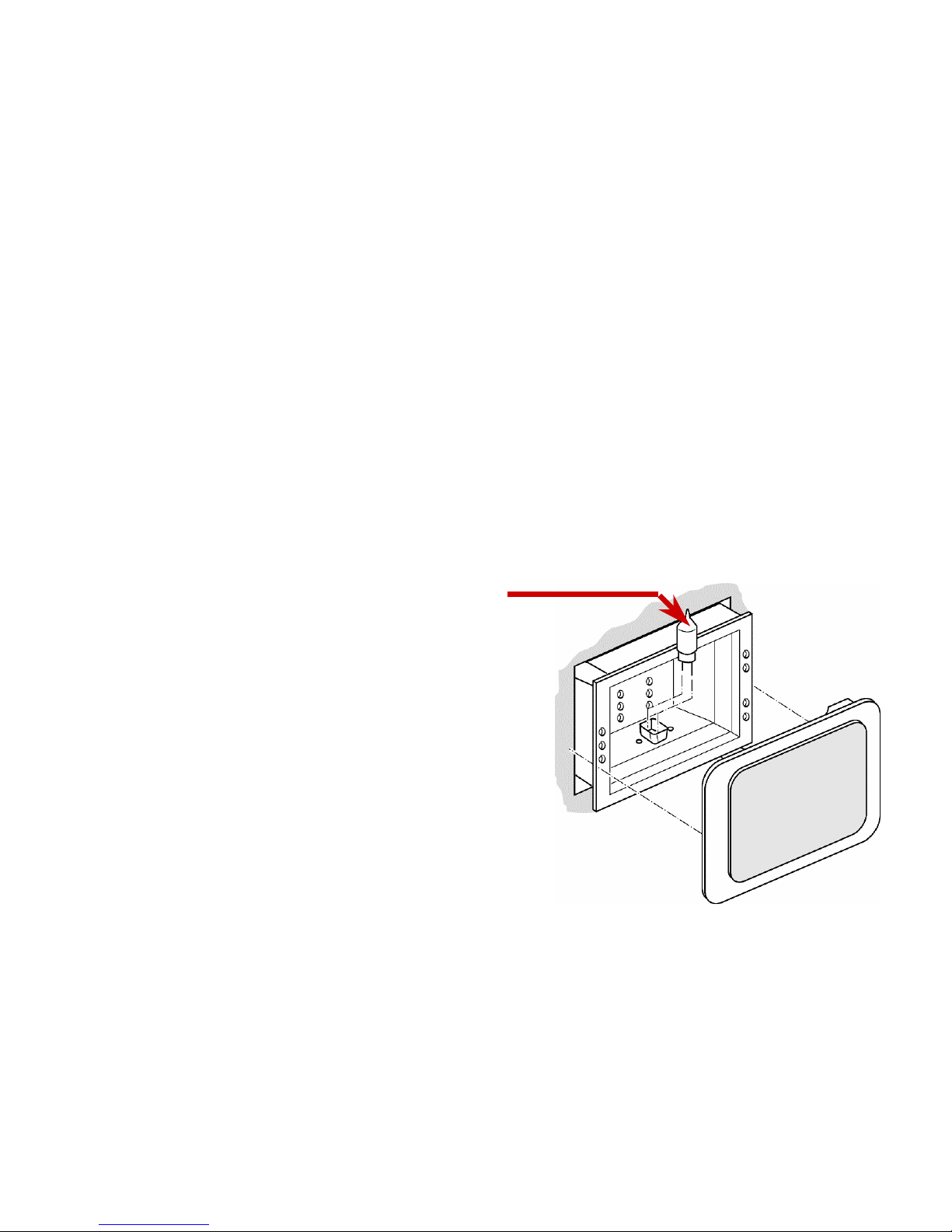
Component Description
Halogen Lights
Component Description
Halogen Lights
ä
ä
Activated by 12VAC from
Activated by 12VAC from
transformer
transformer
ä
ä
Comes on when light pad is
Comes on when light pad is
selected
selected
ä
ä
Comes on when door is
Comes on when door is
opened
opened
ä
ä
Don’t touch bulb with
Don’t touch bulb with
fingers use a tissue as
fingers use a tissue as
grease from fingers can
grease from fingers can
shorten the life of the bulb
shorten the life of the bulb
10 Watt bulb
10 Watt bulb
Page 77
77
77
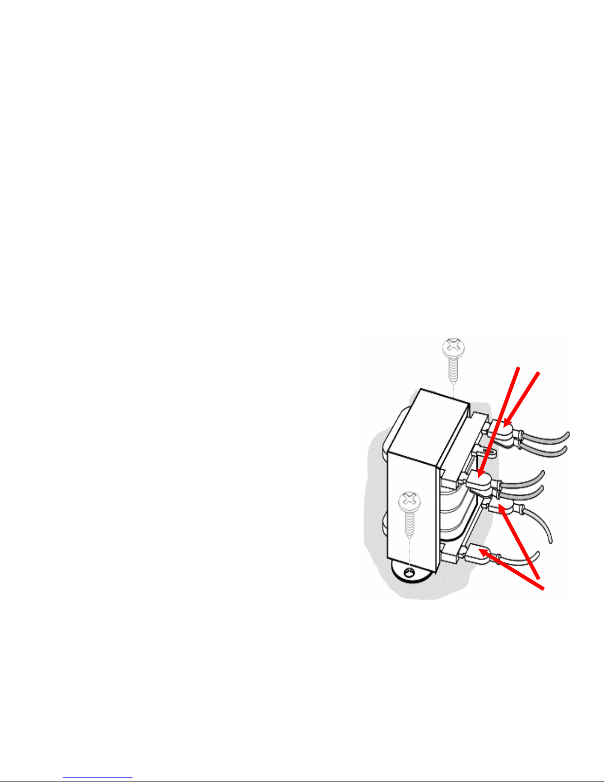
Component Description
Halogen Light Transformer
Component Description
Halogen Light Transformer
ä
ä
Step down Transformer
Step down Transformer
ä
ä
120VAC to 12VAC
120VAC to 12VAC
ä
ä
Activated by relay K7 on
Activated by relay K7 on
main relay board
main relay board
ä
ä
Supplies voltage for
Supplies voltage for
halogen lights
halogen lights
Secondary
Secondary
winding
winding
Primary
Primary
winding
winding
Page 78
78
78
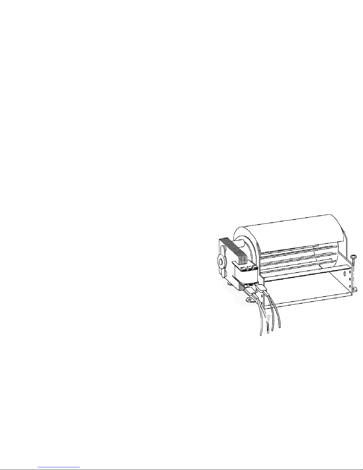
Component Description
Cooling Fan
Component Description
Cooling Fan
ä
ä
Is energized by K6 relay
Is energized by K6 relay
when
when
ever a cooking mode or self-
ever a cooking mode or self-
clean is selected. Continues to
clean is selected. Continues to
run after oven is turned off until
run after oven is turned off until
cavity temperature drops below
cavity temperature drops below
200 degrees F for a cooking
200 degrees F for a cooking
mode & 538 degrees F for self-
mode & 538 degrees F for self-
clean mode. This auto-run
clean mode. This auto-run
feature is controlled by the
feature is controlled by the
sensor
sensor
ä
ä
Oven Blower
Oven Blower
…is 80 CFM at
…is 80 CFM at
outlet
outlet
Page 79

79
79
Air flow pattern
Air flow pattern
Air flow pattern
ä
ä
Natural air enters oven frame at vent holes on both
Natural air enters oven frame at vent holes on both
sides as well as through front grills on oven frame
sides as well as through front grills on oven frame
ä
ä
Action of blower
Action of blower
ä
ä
Moves air across halogen light housings
Moves air across halogen light housings
ä
ä
Pulls air up through doors into plenum area
Pulls air up through doors into plenum area
ä
ä
Air exits out rear of oven into channel
Air exits out rear of oven into channel
ä
ä
Air exhausted out front at bottom of oven on left side
Air exhausted out front at bottom of oven on left side
Page 80

80
80
Component Description
Component Description
Component Description
ä
ä
Convection motor
Convection motor
ä
ä
Bake element
Bake element
ä
ä
Broil element
Broil element
ä
ä
Convection element
Convection element
ä
ä
Door Latch Assembly
Door Latch Assembly
ä
ä
High temp cutout
High temp cutout
ä
ä
Door switch
Door switch
ä
ä
Air switch
Air switch
Page 81
81
81
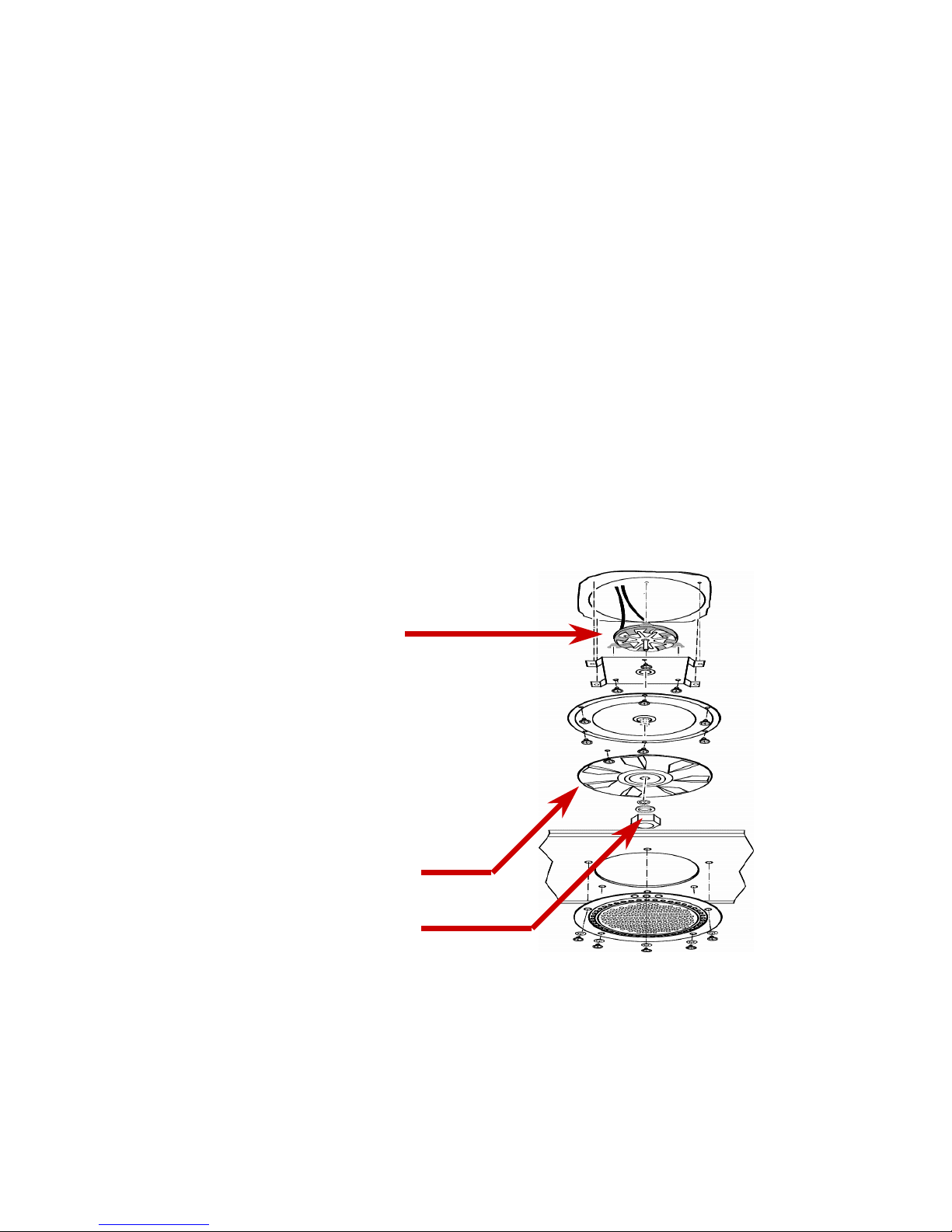
Component Description
Convection Fan Assembly
Component Description
Convection Fan Assembly
ä
ä
Cooling fan blade for
Cooling fan blade for
cooling the motor
cooling the motor
ä
ä
Cooling blade comes
Cooling blade comes
with motor
with motor
ä
ä
Convection fan blade
Convection fan blade
(turns CW)
(turns CW)
ä
ä
LH thread on nut
LH thread on nut
Page 82
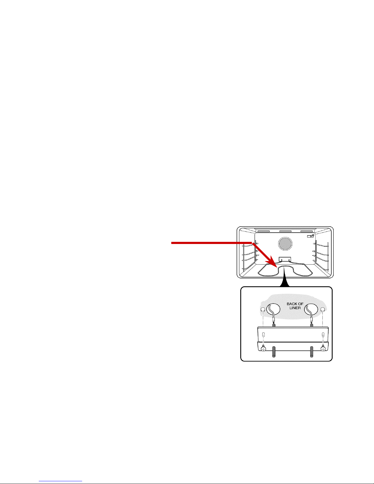
82
82
Component Description
Bake Element
Component Description
Component Description
Bake Element
ä
ä
Bake element is
Bake element is
rated at 2600W
rated at 2600W
Page 83
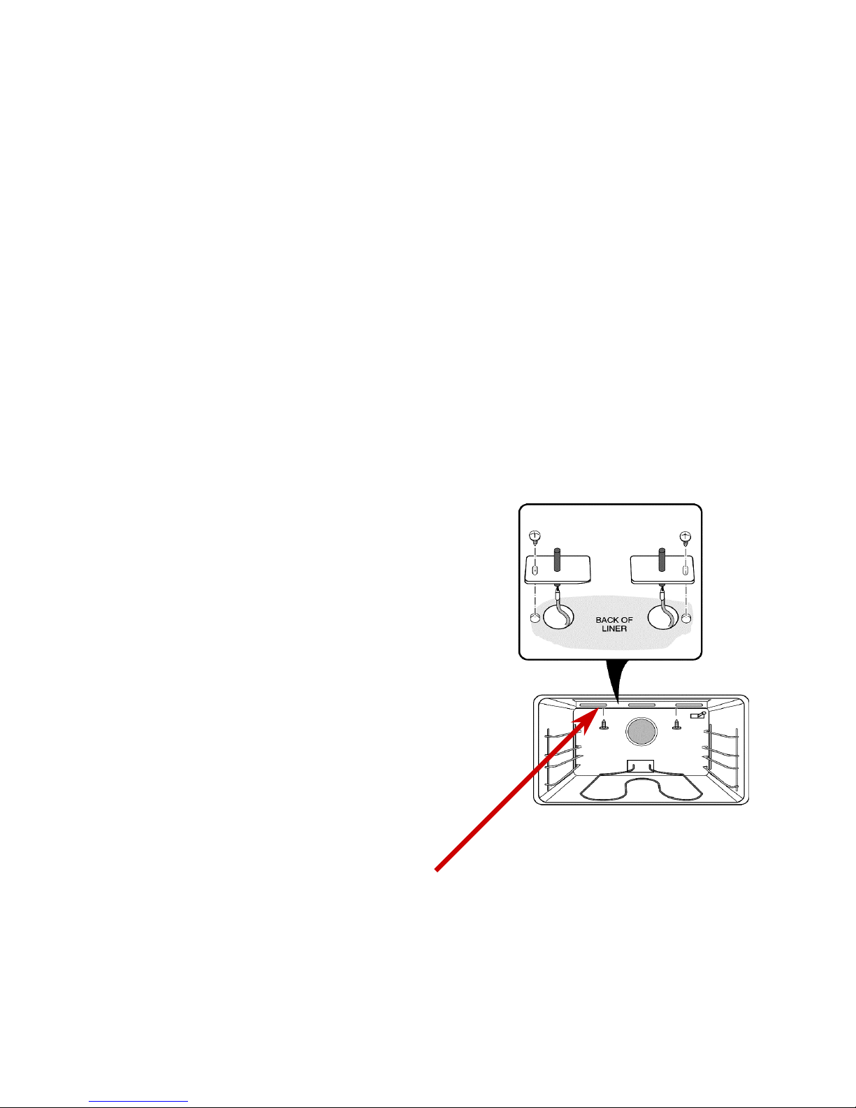
83
83
Component Description
Broil Element
Component Description
Component Description
Broil Element
ä
ä
Rated at 3600 W
Rated at 3600 W
ä
ä
Heats the oven to
Heats the oven to
840 degrees in
840 degrees in
clean cycle
clean cycle
Page 84
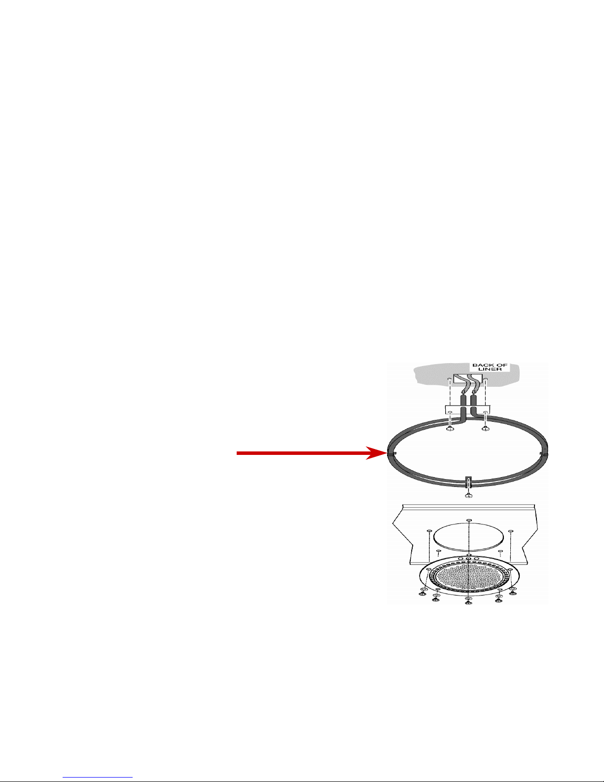
84
84
Component Description
Convection Element
Component Description
Component Description
Convection Element
ä
ä
Rated at 2750 W
Rated at 2750 W
ä
ä
Located on rear
Located on rear
wall of oven
wall of oven
Page 85
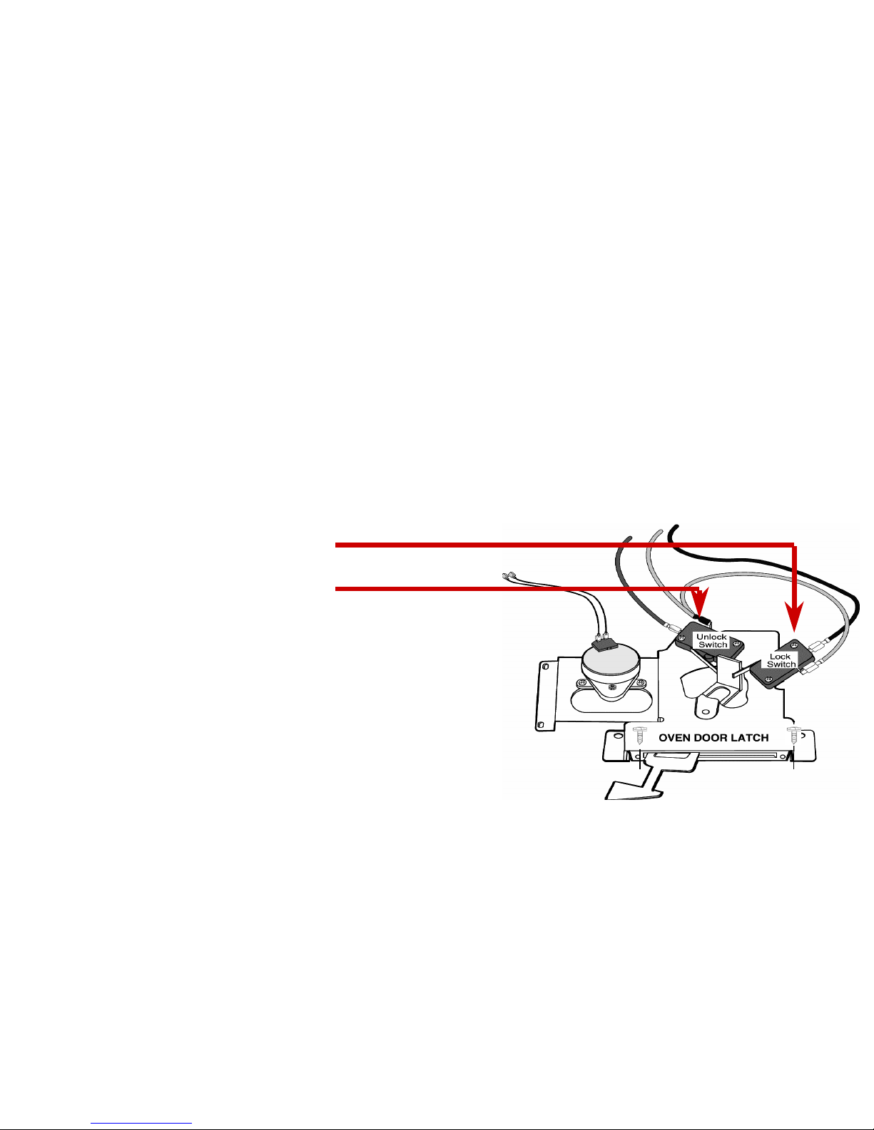
85
85
Component Description
Door Latch Assembly
Component Description
Component Description
Door Latch Assembly
ä
ä
Lock Switch
Lock Switch
ä
ä
Unlock Switch
Unlock Switch
ä
ä
Normal use:
Normal use:
ä
ä
Lock switch….open
Lock switch….open
ä
ä
Unlock switch..closed
Unlock switch..closed
ä
ä
During clean:
During clean:
ä
ä
Lock switch...closed
Lock switch...closed
ä
ä
Unlock switch…open
Unlock switch…open
Latch switches & wiring
Latch switches & wiring
utilize 12VDC circuit
utilize 12VDC circuit
However Latch motor
However Latch motor
runs on 120 VAC
runs on 120 VAC
Page 86
86
86
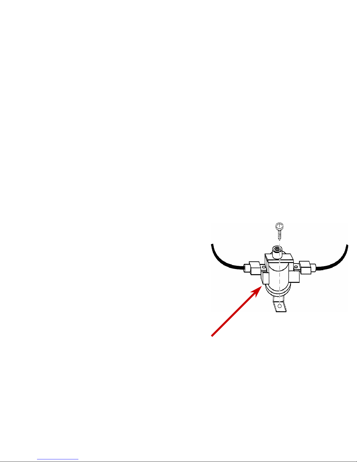
Component Description
High Temp Cutout
Component Description
Component Description
High Temp Cutout
ä
ä
Trips at 350 degrees
Trips at 350 degrees
ä
ä
Will trip if oven interior
Will trip if oven interior
exceeds 975 degrees
exceeds 975 degrees
ä
ä
Disables L1 to stalled fan
Disables L1 to stalled fan
relay contacts
relay contacts
ä
ä
HTC is
HTC is
servicable
servicable
from the front of the oven
from the front of the oven
Page 87
87
87
Component Description
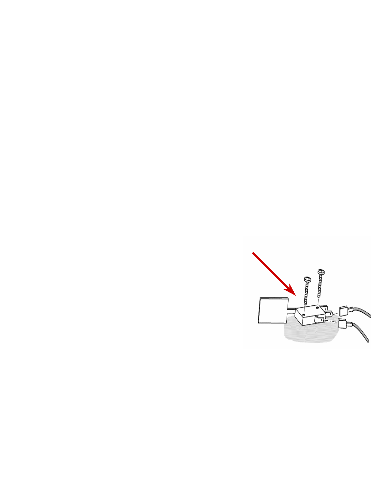
Door Switch
Component Description
Component Description
Door Switch
ä
ä
Serves three functions
Serves three functions
ä
ä
Door open signals board to
Door open signals board to
close K7…. turning on
close K7…. turning on
lights
lights
ä
ä
In clean monitors the fact
In clean monitors the fact
that the door is closed &
that the door is closed &
signals board to power
signals board to power
latch motor
latch motor
ä
ä
When the door is opened, it shuts off the
When the door is opened, it shuts off the
convection fan by de-energizing the K4 relay
convection fan by de-energizing the K4 relay
Page 88
88
88
Component Description
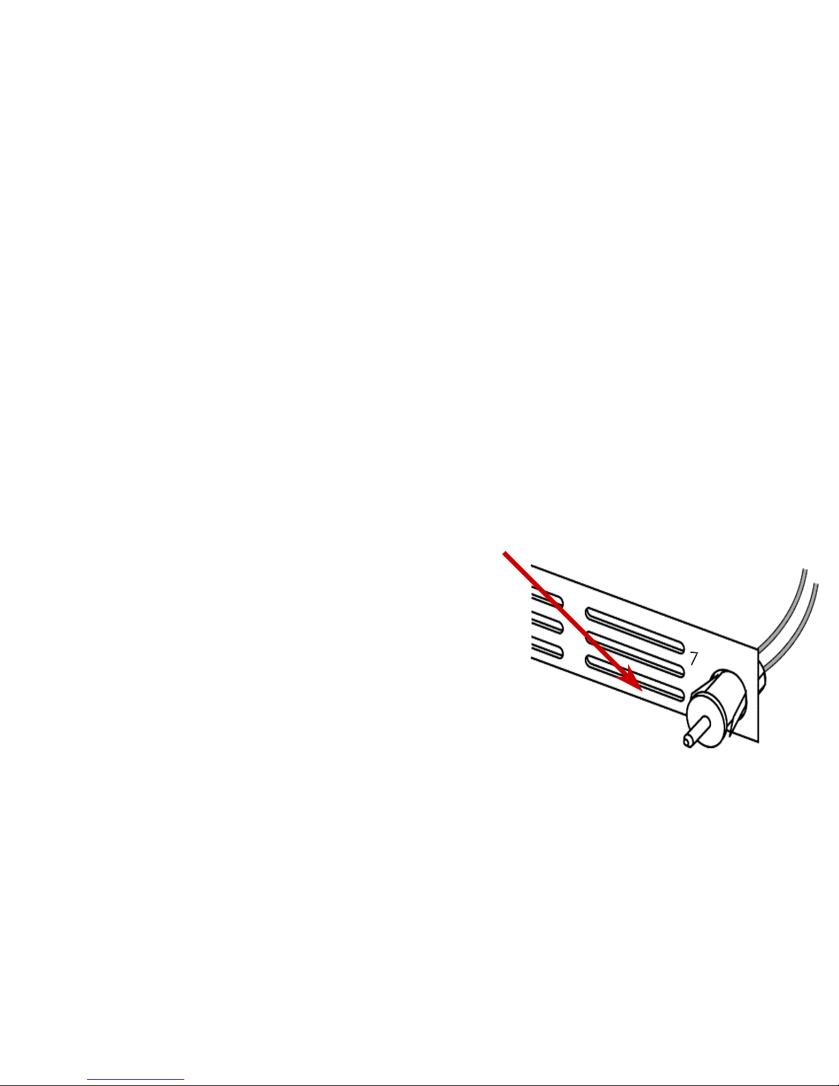
Air Switch
Component Description
Component Description
Air Switch
ä
ä
Mounted in air path of
Mounted in air path of
cooling fan
cooling fan
ä
ä
When closed, it allows for
When closed, it allows for
the activation of the stalled
the activation of the stalled
fan relay
fan relay
ä
ä
Cover must be on back of
Cover must be on back of
oven for correct air flow
oven for correct air flow
over switches
over switches
ä
ä
Conveys 120 VAC
Conveys 120 VAC
Page 89

89
89
Component Description
Oven Module
Component Description
Component Description
Oven Module
ä
ä
A replacement oven cell will include the
A replacement oven cell will include the
following items as a single unit:
following items as a single unit:
ä
ä
Bake element
Bake element
ä
ä
Broil element
Broil element
ä
ä
Halogen lights & cover
Halogen lights & cover
ä
ä
Sensor
Sensor
ä
ä
Insulation
Insulation
ä
ä
Outer panels
Outer panels
Page 90
Page 91
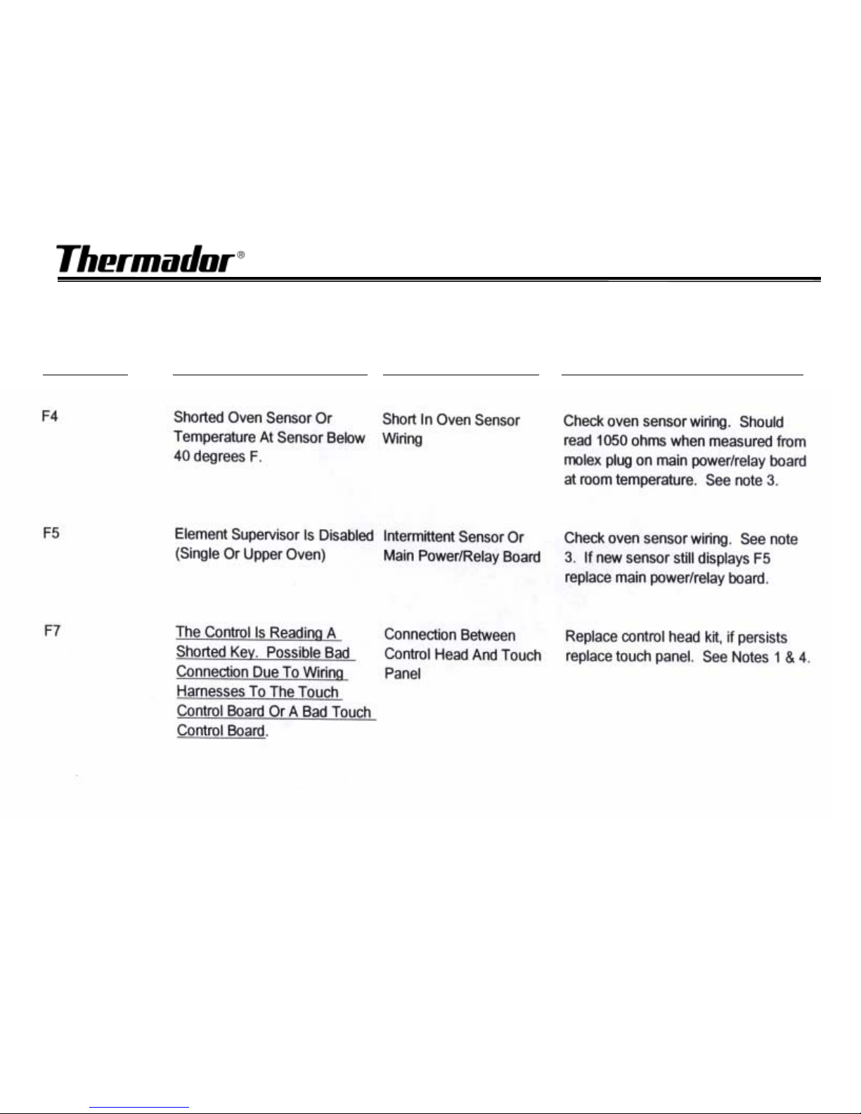
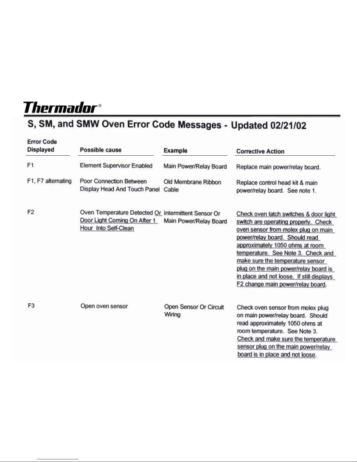
S, SM and SMW Oven Error Code Messages…continued
S, SM and SMW Oven Error Code Messages…continued
Error Code
Displayed Possible Cause Example Corrective Action
Page 92
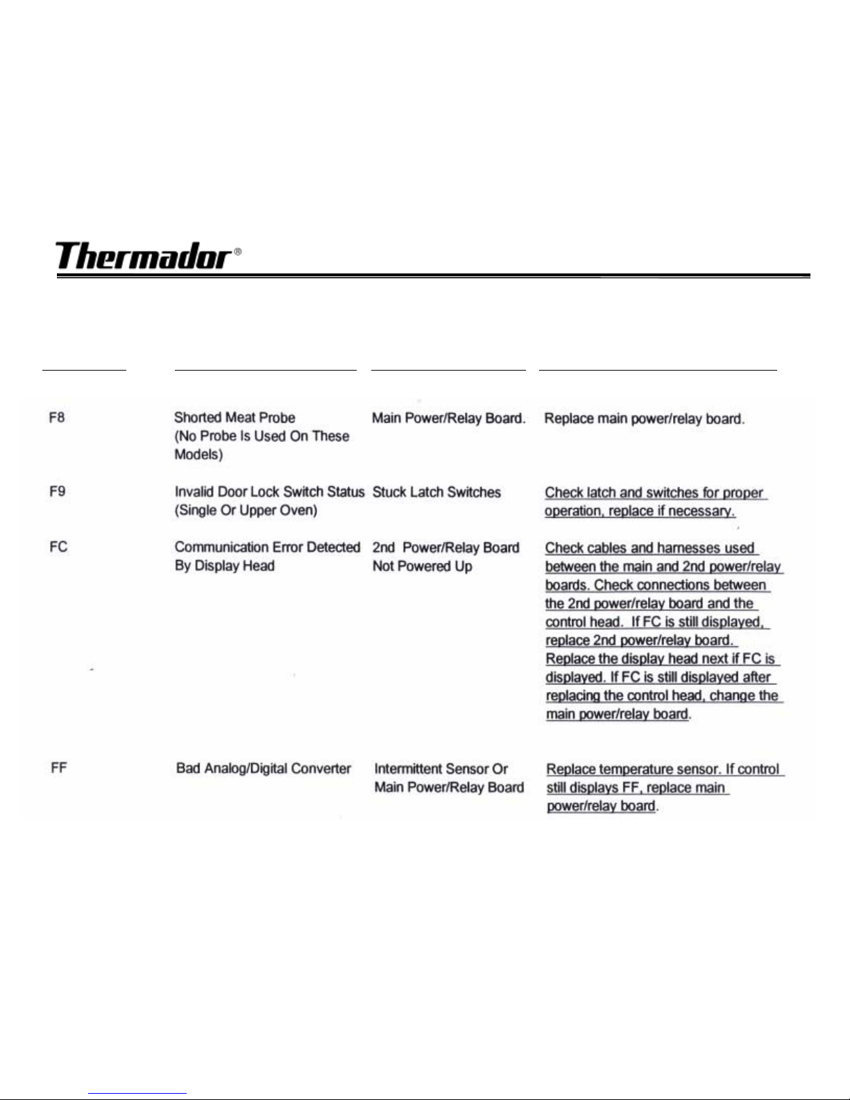
S, SM and SMW Oven Error Code Messages…continued
S, SM and SMW Oven Error Code Messages…continued
Error Code
Displayed
Possible Cause Example Corrective Action
Page 93
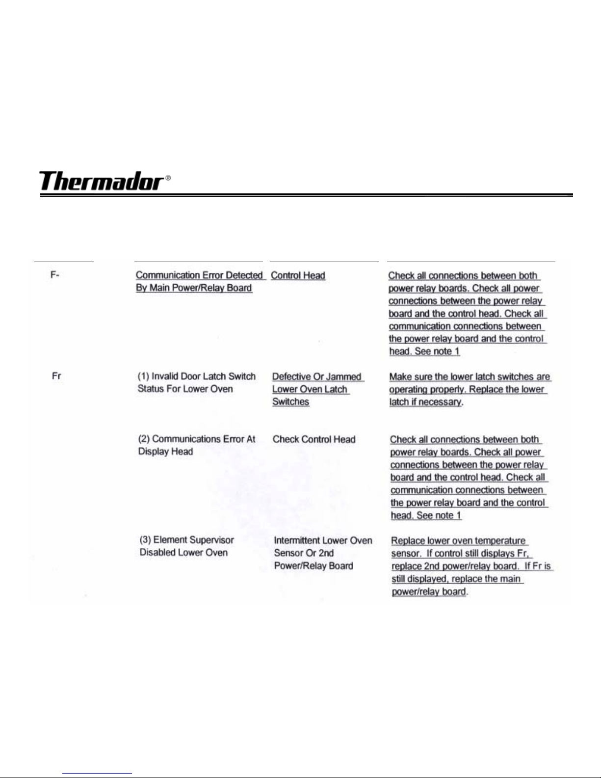
S, SM and SMW Oven Error Code Messages…continued
S, SM and SMW Oven Error Code Messages…continued
Error Code
Displayed
Possible Cause Example Corrective Action
Page 94
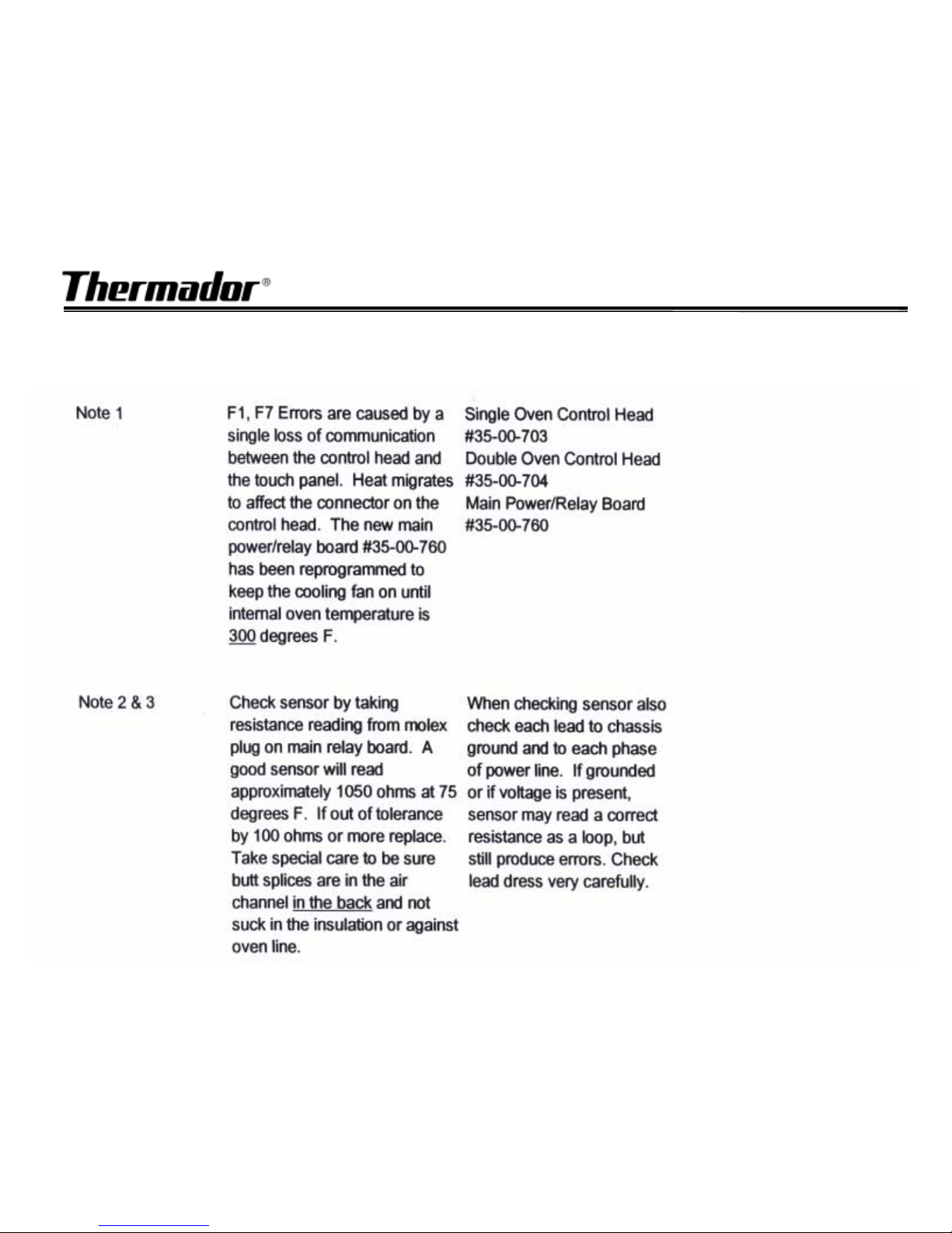
S, SM and SMW Oven Error Code Messages…continued
S, SM and SMW Oven Error Code Messages…continued
Page 95
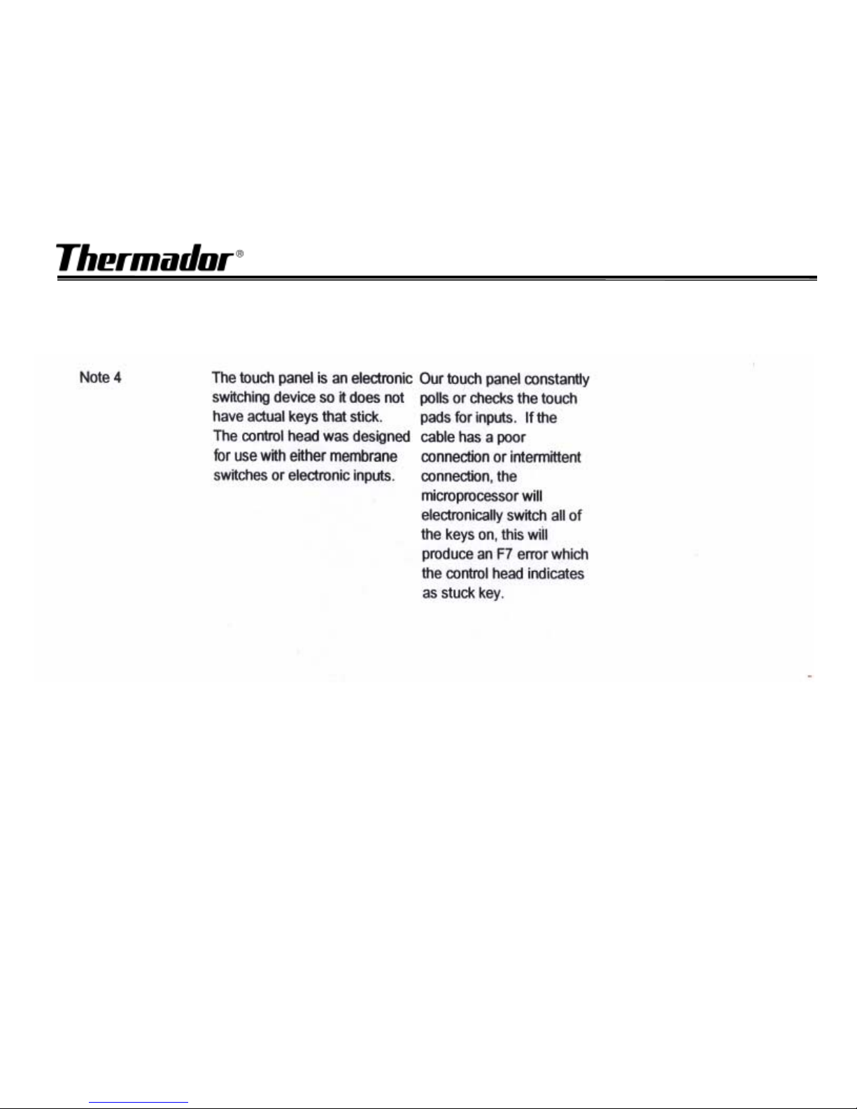
S, SM and SMW Oven Error Code Messages…continued
S, SM and SMW Oven Error Code Messages…continued
Page 96

90
90
HOW THE LOWER OVEN
WORKS
HOW THE LOWER OVEN
HOW THE LOWER OVEN
WORKS
WORKS
ä
ä
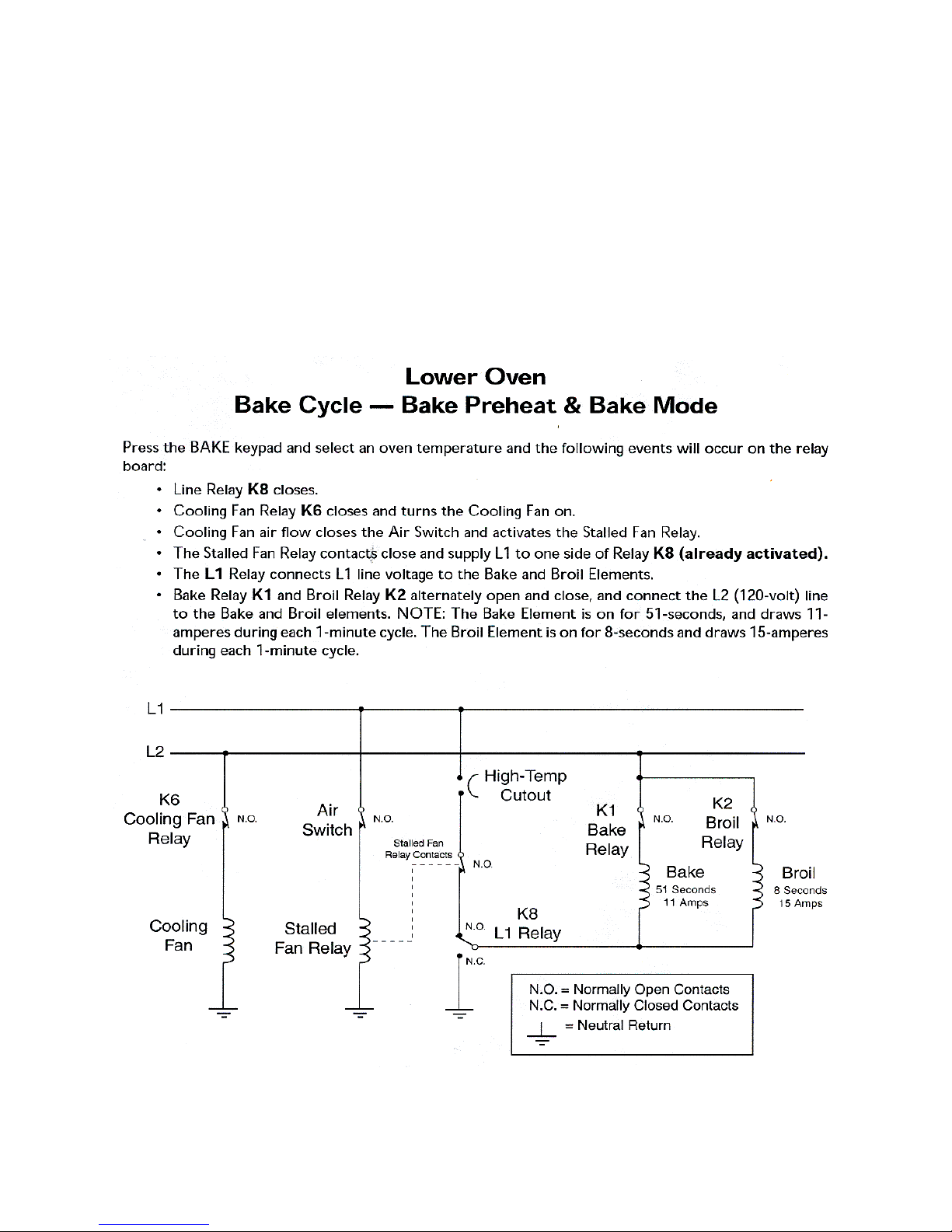
BAKE CYCLE
BAKE CYCLE
ä
ä
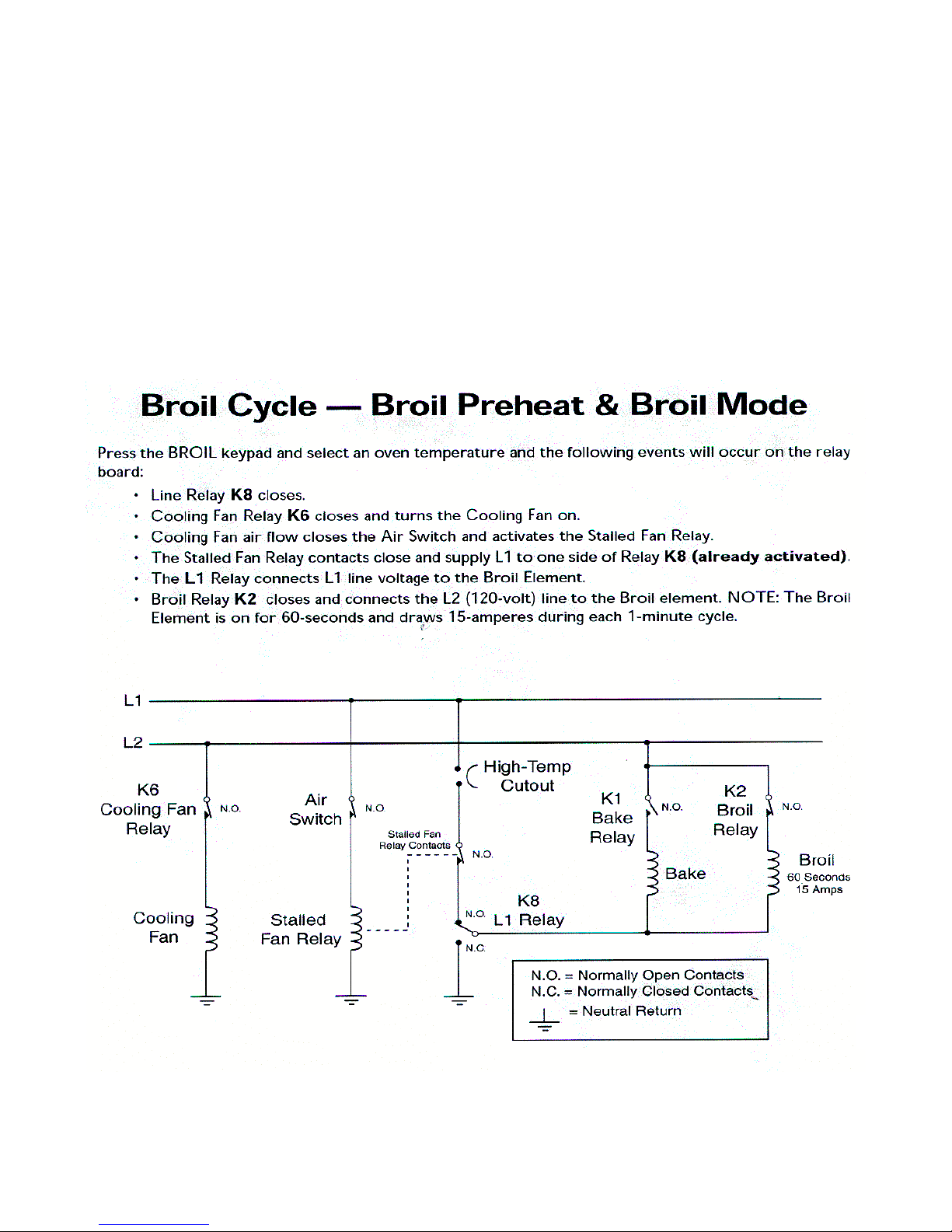
BROIL CYCLE
BROIL CYCLE
ä
ä
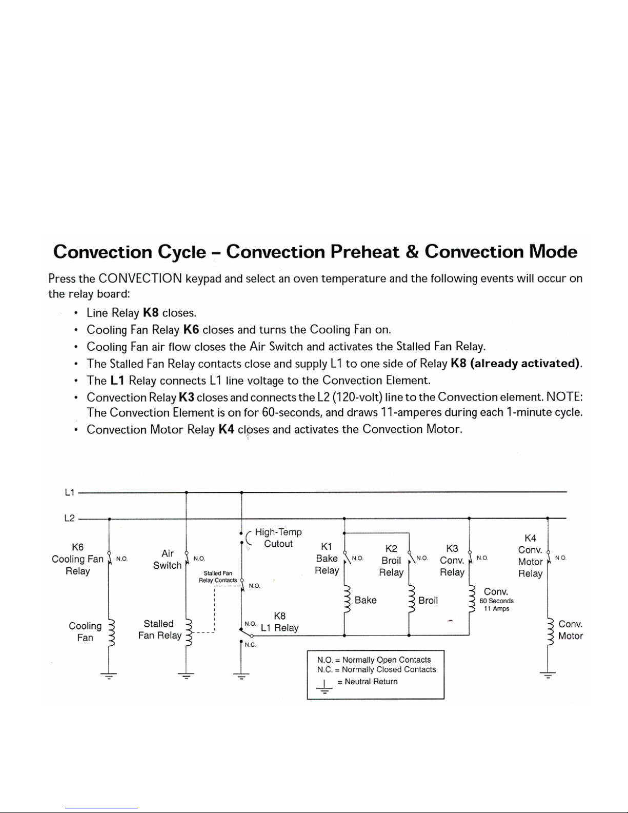
CONVECTION BAKE
CONVECTION BAKE
ä
ä
CONVECTION ROAST
CONVECTION ROAST
ä
ä
CLEAN CYCLE
CLEAN CYCLE
Page 97
91
91
N/C
N/C
Page 98
92
92
N/C
N/C
92
92
Page 99
93
93
93
93
N/C
N/C
Page 100
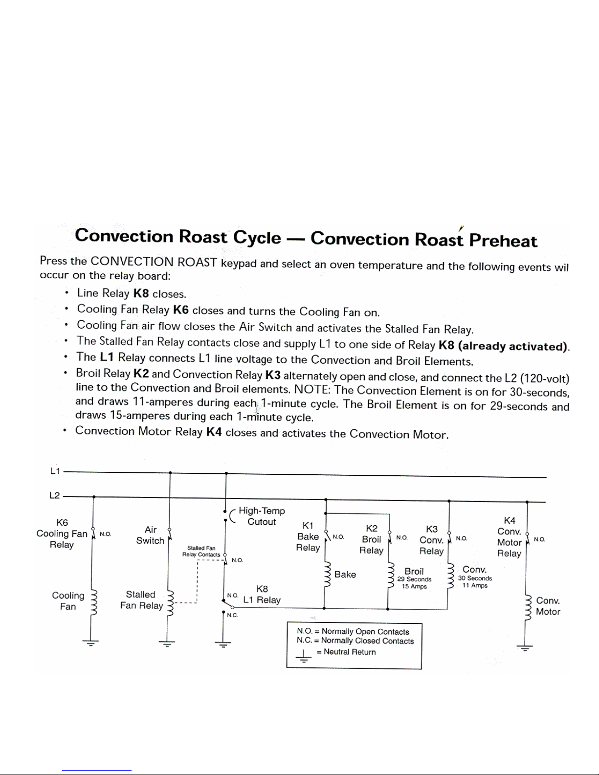
94
94
94
94
N/C
N/C
 Loading...