

Page 1

LP GAS CONVERSION INSTRUCTIONS
For Thermador Professional® Cooktops and Dual Fuel Ranges
INSTRUCTIONS DE
CONVERSION DE GAZ LP
Pour toutes les cuisinières mixtes
Thermador Professional
®
INSTRUCCIONES DE
Model/
Modèle /
Modelo:
PLPKIT
CONVERSION DE GAS LP
Para Parillas y Estufas de Todo Tipo de Gas
Thermador Professional
®
Page 2

Table of Contents
Safety . . . . . . . . . . . . . . . . . .1
Important Safety Instructions . . . . . . . . 1
Conversion Instructions . . .2
Before You Begin . . . . . . . . . . . . . . . . . . 2
Possible Tools Needed for All Orifice
Conversions . . . . . . . . . . . . . . . . . . . . 2
Table 1: Conversion Kit Contents . . . . 2
Table 2: LP Orifice Conversion Chart—
by Model Number (older models /
newer models) . . . . . . . . . . . . . . . . . . 3
Replacing Burner Orifices in Cooktop /
Rangetop . . . . . . . . . . . . . . . . . . . . . . . . . 5
Replace the Star® Burner orifices—
all models . . . . . . . . . . . . . . . . . . . . . . 5
Replace the Gas Grill Orifice—if equipped
with Open-Grate Style Grill . . . . . . . . . 6
Replace the Gas Grill Orifice—if equipped
with Solid-Plate Style Grill . . . . . . . . . . 7
Replace the Gas Griddle Orifice—
if so equipped . . . . . . . . . . . . . . . . . . . 9
Replace the Wok Orifice in Pro Cooktop—
if so equipped . . . . . . . . . . . . . . . . . . 10
Accessing the Gas Regulator . . . . . . . 11
Converting the Regulator to
LP Operation . . . . . . . . . . . . . . . . . . . . . 12
Harper-Wyman regulator conversion 12
Maxitrol regulator conversion . . . . . . 13
Setting Manual Valve Screws for
Cooktop / Rangetop . . . . . . . . . . . . . . . 13
Screw driver for valve screw setting . 13
PRO-GRAND™ and PRO-HARMONY™
Dual-Fuel Ranges and Pro Cooktops 14
Older models of Professional® Dual-Fuel
Ranges and Cooktops . . . . . . . . . . . . 14
Check for Gas Leaks . . . . . . . . . . . . . . 15
Gas leakage checking using a liquid
solution . . . . . . . . . . . . . . . . . . . . . . . 15
Burner Testing and Adjustment . . . . . 16
Checking manifold pressure
(if necessary) . . . . . . . . . . . . . . . . . . . 16
Checking LP flame characteristics and
burner performance . . . . . . . . . . . . . . 16
Tubular and wok burner performance
and final air-shutter adjustments
(if necessary) . . . . . . . . . . . . . . . . . . . 17
Final Step—Placement of LP Conversion
Label . . . . . . . . . . . . . . . . . . . . . . . . . . . 18
Location of Rating Labels on Thermador
Professional® products . . . . . . . . . . . 19
This Thermador Appliance is made by
BSH Home Appliances Corporation
5551 McFadden Ave.
Huntington Beach, CA 92649
Questions?
1-800-735-4328
www.thermador.com
We look forward to hearing from you!
Page 3

Safety
Important Safety Instructions
PLEASE READ ENTIRE INSTRUCTIONS BEFORE PROCEEDING
Natural Gas to Propane (LP) Gas Conversion Kit for
Thermador Professional
Ranges
FOR RESIDENTIAL USE ONLY
IMPORTANT:
Only a qualified service technician or installer should make
this conversion.
INSTALLER:
Please leave these Conversion Instructions with this unit
for the owner.
OWNER:
Please retain these instructions for future reference.
®
Contains Star
conversion to Propane Gas operation for all burners in
cooktop or rangetop section of the following series models.
Save the natural gas parts for possible conversion from LP
back to the natural gas in the future.
This kit is used to convert Thermador Professional
Cooktops, PRO-GRAND™ Dual-Fuel Ranges, and PROHARMONY™ Dual-Fuel Ranges, from natural gas to
Propane (LP) Gas operation. This kit cannot be used to
convert older models of Thermador Professional cooktops
or ranges other than those identified in these instructions
(see TABLE 2). This kit cannot be used to convert
Thermador Professional
or any other brand of appliance.
Burner orifices and hood orifices for proper
®
Cooktops and Dual Fuel
®
®
All Gas Ranges, oven burners,
WARNING:
This conversion kit shall be installed
by a qualified service agency in
accordance with the manufacturer’s
instructions and all applicable codes
and requirements of the authority
having jurisdiction. If the information
in these instructions is not followed
exactly, a fire, explosion or
production of carbon monoxide may
result causing property damage,
personal injury or loss of life. The
qualified service agency is
responsible for the proper
installation of this kit. The
installation is not proper and
complete until the operation of the
converted appliance is checked as
specified in the manufacturer’s
instructions supplied with the kit.
CAUTION:
Disconnect gas and electric power before
making conversion. Before turning power ON,
be sure that all controls are in the OFF position.
To the Service Agent:
It is important that you know the following BEFORE you
begin the gas conversion of the appliance.
• Confirm that the Propane (LP) Gas supply system is
available and ready to use. This is part icu lar ly
important for new construction.
• You must plan for sufficient time and resources to
perform the LP conversion process properly and
completely before leaving the job site. Every step
described in these instructions must be performed to
safely convert the appliance for proper operation on
Propane Gas. INCOMPLETE OR INADEQUATE GAS
CONVERSION OF THE APPLIANCE CAN CREATE A
SAFETY HAZARD.
English 1
Page 4
California Safe Drinking Water and Toxic Enforcement Act (Proposition 65) Notice:
WARNING:
This product contains or, through ordinary use
for its intended purpose, facilitates emission of a
chemical or chemicals known to the State of
California to cause cancer and/or birth defects
or other reproductive harm. To mi n im iz e
exposure to these chemicals:
Conversion Instructions
Before You Begin
1. Perform the LP conversion according to the instructions in this manual.
2. The conversion and adjustment to the burners should be done by a certified installer or agency to ensure proper combustion.
3. Always operate the unit according to the instructions provided with your Range or Cooktop.
4. Ensure proper ventilation with an open window or use a ventilation fan or hood when cooking with Gas.
CAUTION:
Before proceeding with the conversion, shut off
the gas supply to the appliance prior to
disconnecting the electrical power.
Possible Tools Needed for All Orifice Conversions
• Scissors
• 7mm nut driver
• 1/2" deep-well socket and drive
• 1/4" nut driver or wrench
• Large, slotted screwdriver, .40" X .050" blade
• Extra large, slotted screwdriver, .60" X .060" blade
• 7/8" wrench or socket and drive
• Precision, slotted screwdriver, 1/8" X .020" blade
• Phillips #2 screwdriver
• Soap and water mixture or leak-check solution
Table 1: Conversion Kit Contents
Description
PLPKIT Instructions 552805 1 Foam Tape, 1” piece 418145 1 Propane Conversion
Label
Service
Number
418146 1
Quantity
Table 1: Conversion Kit Contents
Description
Plastic Bag 418148 1 Star Burner Jet
Orifice
Grill Hood Orifice
(open grate style)
Grill Hood Orifice
(solid plate style) Griddle Hood Orifice 418150 1 Wok Hood Orifice 414918 1 This Propane Conversion Kit contains the quantities of
parts indicated above; however, some parts will not be
used depending upon the type and model of appliance
being converted to LP Gas. Refer to Table 2 for a listing
of appropriate combination of orifices to be used for
each particular model.
Service
Number
424851 6
418151 1
414916 1
Quantity
CAUTION:
When connecting the unit to propane gas, make
certain the propane gas tank is equipped with its
own high pressure regulator. The maximum gas
pressure to this appliance is not to exceed 14.0
inches water column from the propane gas tank
regulator.
English 2
Page 5
When properly converted using the prescribed LP orifices,
the burners will operate at the following flow rates using
Propane (LP) Gas:
•Star
• Gas Grill (open grate style) — 17,000 BTU/hr. [4.98
• Gas Grill (solid plate style) — 12,000 BTU/hr. [3.51
• Gas Griddle — 13,000 BTU/hr. [3.81 kW], using a #57
• Gas Wok — 24,500 BTU/hr. [7.17 kW], using a #54 or
Table 2: LP Orifice Conversion Chart—by Model Number (older models / newer models)
®
Burners — 13,000 BTU/hr . [3.81 kW] each, u sing
1.07mm orifices.
kW], using a 1.20mm orifice.
kW], using a #59 orifice.
or 1.10mm orifice.
1.40mm orifice.
WARNING:
NEVER leave the gas conversion partially
completed. If the appliance is operated while the
gas conversion is incomplete, high levels of
carbon monoxide may be emitted, or a fire or
explosion may occur.
WARNING:
If the Natural Gas orifices are left in place while
attempting to operate the appliance using
Propane (LP) Gas, at the higher pressure
setting for LP Gas, the burners will produce
large flames which may emit high levels of
carbon monoxide into the room, or a fire or
explosion may occur.
Appliance Model Numbers
(older/newer)
Pro Cooktops:
PC304 / PCG304E 4 each - 1.07mm
PC366 / PCG366E 6 each - 1.07mm
PC364GD / (no newer model) 4 each - 1.07mm #57 or 1.10mm
PC364GE / PCG364ED 4 each - 1.07mm
PC364GL / PCG364EL 4 each - 1.07mm 1.20mm (grate) or
PC486GD / (no newer model) 6 each - 1.07mm #57 or 1.10mm
PC486GE / PCG486ED 6 each - 1.07mm
PC486GL / PCG486EL 6 each - 1.07mm 1.20mm (grate) or
PC484GG / (no newer model) 4 each - 1.07mm 1.20mm (open grate
PC484GGE / PCG484EC 4 each - 1.07mm 1.20mm (grate) or
PC484WK / PCG484EW 4 each - 1.07mm #54 or 1.40mm
PC484GE / PCD484EE 4 each - 1.07mm
Star Burners
#424851
Jet Orifice
Gas Grill*
(Grate/Plate Styles)
#418151 or #414916
Hood Orifice
#59 (plate)
#59 (plate)
grill only)
#59 (plate)
Gas Griddle**
#418150
Hood Orifice
#57 or 1.10mm
Gas Wok
#414918
Hood Orifice
PRO-GRAND™ Dual-Fuel Ranges (27" depth):
PD304 / PRD304EG 4 each - 1.07mm
PD366 / PRD366EG and
PRD366EPG
PD364GD / (no newer model) 4 each - 1.07mm #57 or 1.10mm
PD364GE / PRD364EDG and
PRD364EDPG
6 each - 1.07mm
4 each - 1.07mm
English 3
Page 6

Table 2: LP Orifice Conversion Chart—by Model Number (older models / newer models)
Appliance Model Numbers
(older/newer)
PD364GL / PRD364ELG 4 each - 1.07mm 1.20mm (grate) or
PD486GD / (no newer model) 6 each - 1.07mm #57 or 1.10mm
PD486GE / PRD486EDG and
PRD486EDPG
PD486GL / PRD486ELG 6 each - 1.07mm 1.20mm (grate) or
PD484GG / (no newer model) 4 each - 1.07mm 1.20mm (open grate
PD484GGE / PRD484ECG 4 each - 1.07mm 1.20mm (grate) or
PD484GE / PRD484EEG 4 each - 1.07mm
PRO-HARMONY™ Dual-Fuel Ranges (24" depth):
DP304 / PRD304EH 4 each - 1.07mm
DP366 / PRD366EH 6 each - 1.07mm
DP364GE / PRD364EDH 4 each - 1.07mm
DP364GL / PRD364ELH 4 each - 1.07mm #59 (solid plate grill
Star Burners
#424851
Jet Orifice
6 each - 1.07mm
Gas Grill*
(Grate/Plate Styles)
#418151 or #414916
Hood Orifice
#59 (plate)
#59 (plate)
grill only)
#59 (plate)
only)
Gas Griddle**
#418150
Hood Orifice
#57 or 1.10mm
Gas Wok
#414918
Hood Orifice
(no older model) / PRD486EDH 6 each - 1.07mm
(no older model) / PRD486ELH 6 each - 1.07mm #59 (solid plate grill
only)
(no older model) / PRD484ECH 4 each - 1.07mm #59 (solid plate grill
only)
(no older model) / PRD484EEH 4 each - 1.07mm
NOTES:
* Some newer-model Pro Cooktops and Pro-Grand DF Ranges have the open grate style Gas Grill.
** Older model numbers with letters "GE" and newer "E" model numbers that have letters "ED", "EC", or "EE" are for
models with Electric Griddle -- which do not require conversion.
Examples
High Altitude:
Many of the Thermador appliances that are serviced by this
Propane (LP) conversion kit are CSA-certified for safe
operation on LP Gas up to an elevation of 10,200 ft.
[3,109m] above sea level without additional alterations. For
: "PC484GGE", "DP364GE", "PRD364EDG", "PRD484ECH", or "PCD484EE".
safe LP conversion of an appliance for use at higher
elevations, consult the local gas company for their
recommendations for correct orifice sizes an d an y oth er
necessary adjustments that will provide proper gas
combustion at high altitudes.
English 4
Page 7

Replacing Burner Orifices in Cooktop / Rangetop
NOTICE:
After the replacement of each orifice, and before
reassembly of the burner, perform a brief gas leakage
check of the orifice and associated fittings, per the "Check
for Gas Leaks" section of these instructions.
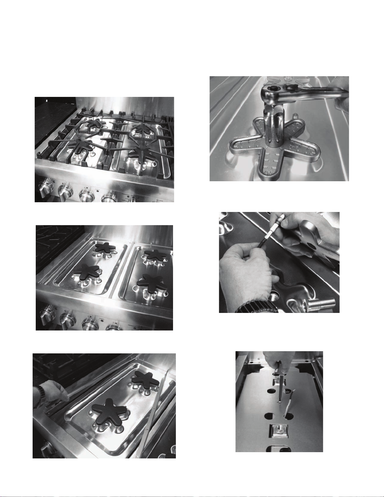
Replace the Star® Burner orifices— all models
• Cut a 3/8" long piece of the adhesive foam strip
supplied in the kit and place over the edge of the nut
®
driver used to replace the Star
shown.
Burner orifices, as
• Use a 7mm nut driver to reach down through the
venturi and remove the orifice from the burner's jet
holder.
• Replace each star burner jet orifice with one of the
1.07mm, LP jets supplied in the kit. These are sized for
the Star
flow rate using Propane (LP) Gas.
®
Burners to produce 13,000 BTU/hr . [3.81 kW]
Foam Strip
The foam piece helps to retain the orifice in the end of
the nut driver, so it will not fall inside the appliance
during orifice removal or installation.
• Perform a brief gas leakage test of each orifice and
associated supply tube fittings, per the "Check for Gas
Leaks" section of these instructions. Proper access to
the burner's jet holder can be accomplished after spill
tray removal—see "Accessing the Gas Regulator"
section for instructions on how to remove the spill tray.
English 5
Page 8
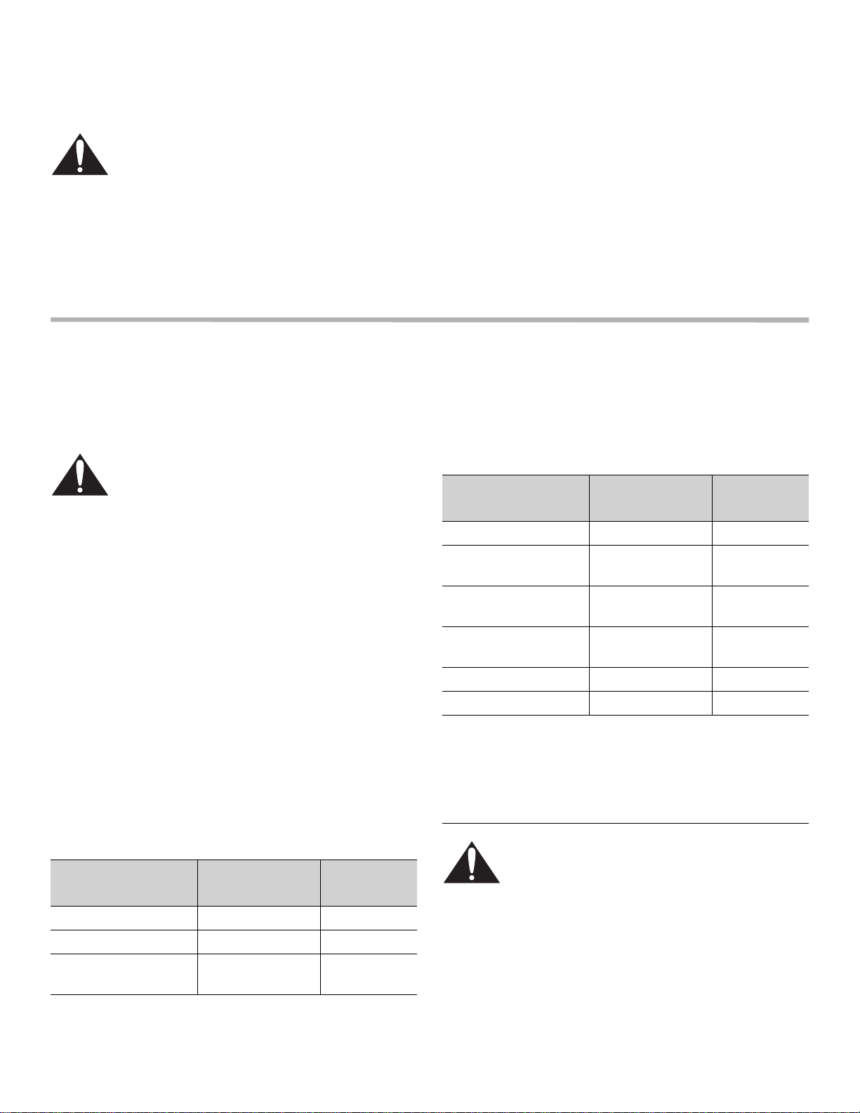
• Each orifice is stamped "107" (for 1.07mm orifice
diameter) as shown.
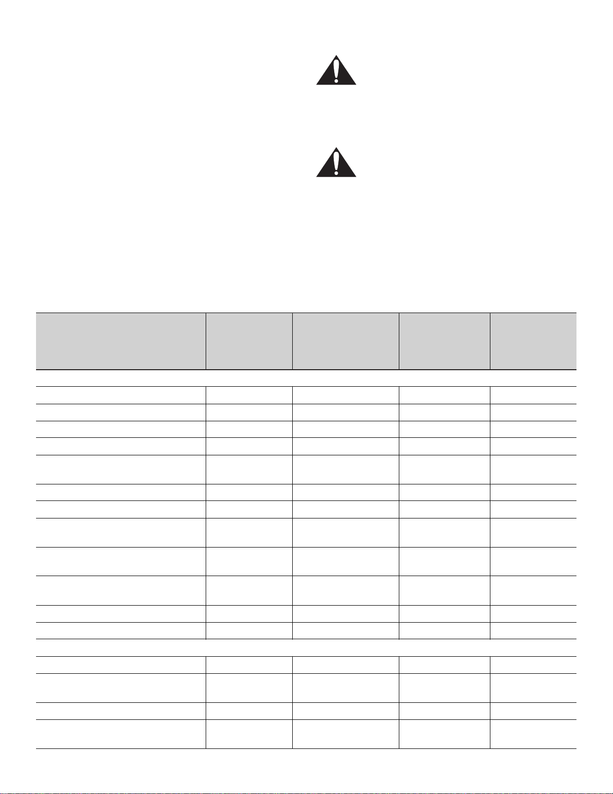
Replace the Gas Grill Orifice—if equipped with Open-Grate Style Grill
This style grill is an open-top design that can be identified
by its "U" shaped burner tube and corrugated stainlesssteel radiant, as shown in the exploded view.
WARNING
The grill must be assembled as shown. The drip
tray heat shields must be in place, and the
burner must be properly positioned relative to
the gas supply. Incorrect assembly of the grill
may result in unsafe or hazardous conditions
during operation.
• Remove the Grill Grate, Radiant, and Grill Burner from
the Grill Can Assembly.
• Pull back the metal lever at the front of the Grill Burner
to release it, and then remove the Grill Burner.
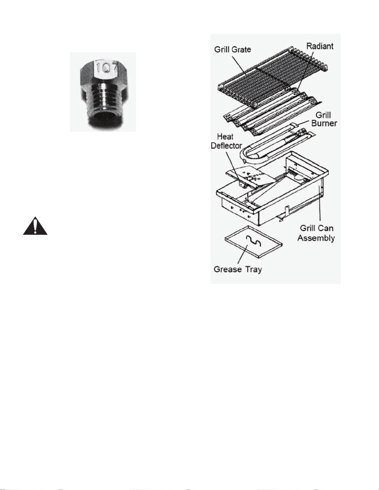
• Use a 1/2" deep-well socket to remove the Grill hood
orifice and replace with the 1.20mm LP hoo d orifice
supplied in this kit.
• Pre-adjust the burner's air shutter to approximately
75% closed (approximately 0.20" opening) position and
re-tighten screw(s) using a 1/4" nut driver or wrench.
• Re-insert the venturi end of the Grill Burner into the two
slots at the back of the Grill Can Assembly. Then rotate
the other end of the burner into position and lock the
tab on the front of the burner into the slot in the Heat
Deflector.
• Re-install the stainless steel Radiant onto the two studs
on each end of the Grill Can Assembly.
English 6
Page 9
• Replace the Grill Grate such that the raised food
containment rail is oriented toward the back of the Grill.
• The "1.20MM"-stamped hood orifice is sized to
produce 17,000 BTU/hr . [4.98 kW], using Propane (L P)
Gas.
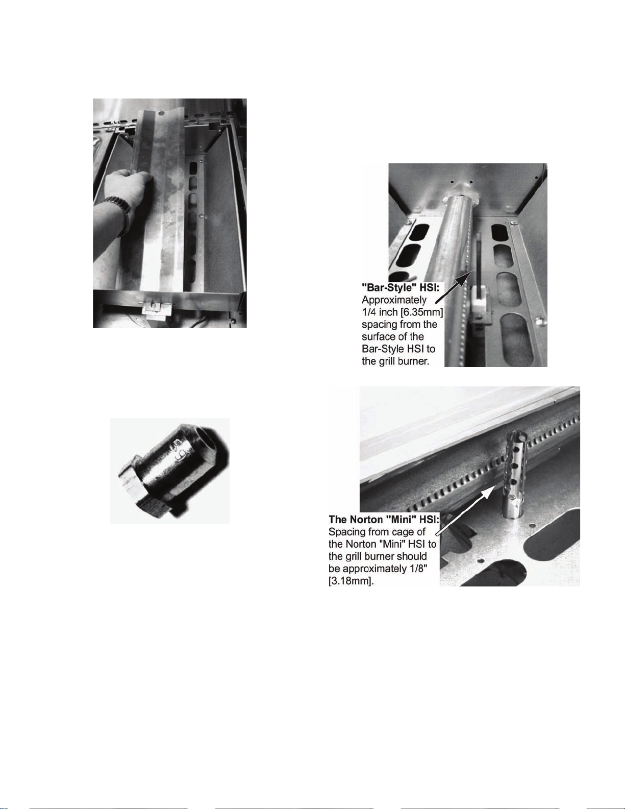
Replace the Gas Grill Orifice—if equipped with Solid-Plate Style Grill
This style grill design can be identified by its ribbed grill
plate and its "T" shaped burner, as shown in the exploded
view.
• After the orifice conversion, gas leak check, and reinstallation of the grill burner, check that the electrode
and bracket spacing to the burner is within the distance
range shown here.
• Verify that the grill burner's air shutter is properly readjusted, per the “Burner Testing and Adjustment"
section of these instructions, as air-shutter position can
also influence ignition performance.
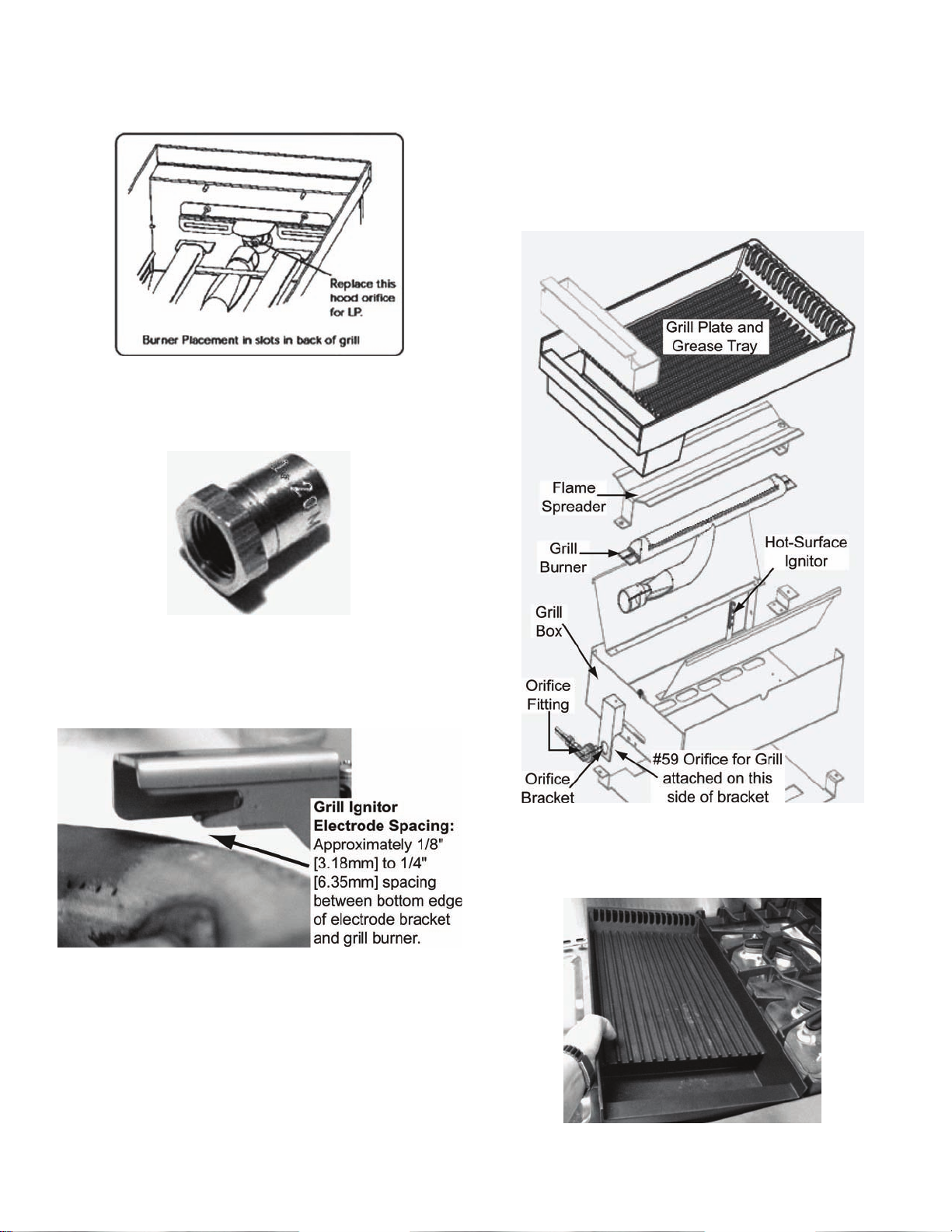
• Remove the Grill Plate. Some Grills have a Grill Plate
and Frame as two separate pieces, similar to the Gas
Griddle on the next pages.
English 7
Page 10
• Remove the screws at each end of the Flame
Spreader, tilt to ward you, and pull the spreader out of
the front slot in the Grill Box.
• Use a 1/2" deep-well socket to remove the Grill hood
orifice.
• The LP orifice is a #59 drill (stamped "59"), which is
sized to produce 12,000 BTU/hr. [3.51 kW], using
Propane Gas.
• Pre-adjust the burner's air shutter to approximately
75% closed (approximately 0.20" opening) position and
re-tighten screw(s) using a 1/4" nut driver or wrench.
• After the orifice conversion, gas leak check, and resetting of the grill burner, check that the Hot-Surface
Ignitor (HSI) spacing to the burner is within the
distance ranges shown, for the following two types of
ignitors used with Grill models.
English 8
Page 11

Replace the Gas Griddle Orifice— if so equipped
• The LP orifice is a #57 drill (stamped "57"), which is
sized to produce 13,000 BTU/hr. [3.81 kW], using
Propane (LP) Gas. The orifice diameter could also be
1.10mm; in which case, the hood orifice could have a
"110" or "1.10MM" stamp.
• Pre-adjust the burner's air shutter to approximately
75% closed (approximately 0.20" opening) position and
re-tighten screw(s) using a 1/4" nut driver or wrench.
• Remove the Griddle's Grease Tray, Griddle Plate and
Griddle Frame. These items are not held with
fasteners, so they should lift up and out easily.
• Remove the screws on each end of the Flame
Spreader, while paying attention not to drop the
spacers inside the cooktop / rangetop area.
• Remove the Cover Plate with four (4) screws, which
covers the Griddle Burner's venturi at the bottom of the
Griddle Box.
• Lift out the Griddle Burner.
• Use a 1/2" deep-well socket to remove the Grill hood
orifice. When installing the LP orifice, take extra care
not to bend the sheet metal orifice bracket.
• After the orifice conversion, gas leak check, and reinstallation of the griddle burner, check that the ignitor
electrode tip spacing to the surface of the burner
(tangent point) is approximately 0.105". There is some
movement available in the burner mounting, on each
end, to adjust this spacing if needed.
English 9
Page 12
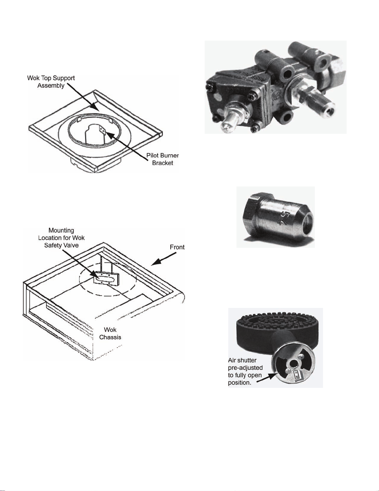
Replace the Wok Orifice in Pro Cooktop— if so equipped
• Remove the two screws that attach the pilot burner to
the bracket on the Wok Top Support Assembly.
• Lift the Top Assembly straight up, away from the Wok
Chassis a few inches, and then remove the Wok
Burner.
• Lift out the Wok Top Support Assembly. This will
expose the Safety Valve.
Wok Safety Valve with Hood Orifice
• The LP orifice for the Wok is a #54 drill (stamped "54"),
which is sized to produce 24,500 BTU/hr. [7.17 kW],
when using Propane (LP) Gas. The orifice diameter
could also be 1.40mm; in which case, the hood orifice
could have a "140" or "1.40MM" stamp.
• Use a 1/2" deep-well socket to remove the hood orifice
from the safety valve.
NOTE:
The pilot burner does not require orifice conversion for
operation on Propane Gas.
• Pre-adjust the air shutter on the Wok Burner to fully
open position.
• Replace the Wok Top Assembly.
• Re-install the wok burner. Make sure that the burner's
venturi is properly positioned on the hood orifice, and
that the bottom of the burner head is positioned
between the pins on the cross member at the base of
the top support.
• Re-attach the pilot burner to the bracket on the Wok
Top Support.
English 10
Page 13
Accessing the Gas Regulator
All dual-fuel range models and some cooktop models have
the gas regulator located inside the cooktop/rangetop,
under the left spill tray .
• Gas regulator is located inside cooktop, left side
• Remove the cooking grates
• Remove Star
both burners using a 13/16" socket or wrench.
• Disconnect the spark wire from the tab on the spark
electrode for each burner.
®
Burner caps, then remove venturi from
• Remove aluminum trim from sides of left spill tray
• Remove the shield on some models. Some models
have a double-width shield that extends under ad jacent
spill tray.
English 11
Page 14

• The gas regulator is located near the left rear corner
inside the cooktop area of appliance.
NOTE:
Fallen star-burner orifices inside cooktop area, from the
replacement process, can usually be retrieved during this
step.
Converting the Regulator to LP Operation
WARNING:
If the Natural Gas orifices are left in place while attempting to operate the appliance using Prop ane (LP) Gas, at
the higher pressure setting for LP Gas, the burners will produce large flames which may emit high levels of
carbon monoxide into the room, or a fire or explosion may occur. All orifice replacements for LP operation
should be performed prior to regulator conversion.
Harper-Wyman and Maxitrol are the two brands of gas regulators that are used on Thermador Professional
Harper-Wyman regulator conversion
• Use a large, slotted screwdriver, with .40" X .050"
blade, to remove conversion cap.
• Using a large screwdriver, press down on conversion
cap and rotate counter-clockwise to release bayonet
mount.
• Flip the conversion cap over to show the recessed
side. "LP" will show at the bottom of the recess.
• Use an extra large, slotted screwdriver, with .60" X
.060" blade, to re-install LP cap.
• Re-insert cap in top of the regulator with rece ss up ,
"LP" visible. Press down and rotate clockwise to lock
cap position.
®
products.
English 12
Page 15
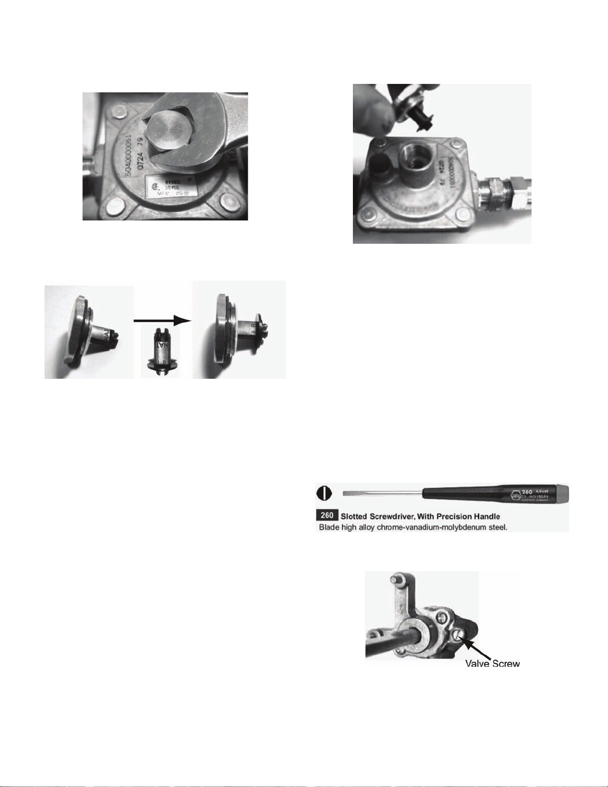
Maxitrol regulator conversion
• Remove conversion cap with a 7/8" socket or wrench.
• Snap-out stem from bottom of the cap, flip stem over to
show "LP" end, and snap stem back into the cap, as
shown.
Flip Stem
• Re-install conversion cap -configured for LP gas- back
into top of the Maxitrol regulator.
Setting Manual Valve Screws for Cooktop / Rangetop
Screw driver for valve screw setting
A precision screwdriver with high-strength blade, similar to
the *Wiha no. 26033, with 1/8" [3.0mm] wide, .020"
[0.50mm] thickness tip, shown below, should be used to reposition the bypass screws for minimum flow settings on
manual valves.
*Used by permission from Wiha Quality Tools division of Willi
Hahn Corporation USA.
English 13
Page 16

PRO-GRAND™ and PRO-HARMONY™ Dual-Fuel Ranges and Pro Cooktops
• Remove knob from the valve stem by slowly pulling
knob straight out, away from control panel.
• For newer models, remove the bezel-mounting screw
located to the right of the valve stem.
• Turn the valve screw clockwise just until "bottom out"
position is reached. DO NOT over-tighten the valve
screw.
• For open-grate style Grill or Wok valves — After turning
valve screw to bottom position, turn screw counterclockwise one-half (1/2) turn.
NOTE:
• It is necessary that the two valves for XLO operation
(farthest left on control panel) are in the OFF position
for proper access to the valve screws through
clearance holes in the XLO potentiometers.
• Solid-plate style Gas Grill and Gas Griddle are
controlled by thermostats and do not have valves that
require adjustments.
Older models of Professional® Dual-Fuel Ranges and Cooktops
• Remove knob from the valve stem by slowly pulling
knob straight out, away from control panel.
• To engage the valve screw, insert precision
screwdriver into hole in bezel created by removal of
mounting screw.
English 14
• Valve screws on older models can be accessed directly
through the control panel, without removing bezel
screws.
Page 17

Check for Gas Leaks
WARNING:
DO NOT use a flame of any kind to check for gas leaks.
WARNING:
Hot Surface Ignitor (HSI) for Grill gets very hot and can cause severe burns.
Gas leakage checking using a liquid solution
All of the replacement orifices in the PLPKIT, LP conversion
kit, have straight threads (not pipe threads) and do not
require thread sealing compound.
Leak-checking should occur after the orifice conversion is
complete, and before the burner is reassembled and
tested.
• Make sure that all of the LP orifices have been
tightened and that all valves and controls are in the
OFF position.
• Turn on electrical and gas supplies.
• Briefly evaluate the threaded connection of each
replaced orifice individually - that is, one orifice at a
time.
• Spray a generous amount of soap and water mixture—
or other solution designed for checking gas leaks—on
the threaded junction at the base of the orifice. Avoid
spraying electrical devices. (A 25% dishwashing liquid
to water mixture is effective for this.)
• Briefly turn on the valve or control while blocking the
orifice hole with a soft pencil eraser, your finger, or
something similar. It is normal to hear spark ignition
noise during this process. —Avoid extreme heat from
the Grill HSI on models so equipped. See warning
above.—
• Monitor the base of the orifice junction to see if bubbles
are forming anywhere around the threaded co nnection.
• Bubbles forming are indications of gas leaks. The
amount and sizes of the bubbles are indications of the
severity of the leakage.
• Repair all gas leaks immediately after their discovery;
this can often be accomplished by re-tightening the
orifice.
• Since considerable torque is sometimes used during
orifice replacement, leak-check other fitting junctions
leading up to the orifice as well.
• Turn off the gas and electrical supplies.
• Reassemble the appliance in preparation for testing
the newly-converted burner systems.
English 15
Page 18

Burner Testing and Adjustment
Checking manifold pressure (if necessary)
Checking the appliance manifold pressure is NOT
REQUIRED for the Propane Gas conversion; however, if
the outlet pressure of the gas regulator or the inlet pressure
to the appliance is suspect, the following procedure can be
used to check the manifold pressure.
• A manifold pressure measurement can be acquired at
one of the star burner orifices, as shown.
Checking LP flame characteristics and burner performance
To observe the burner flames, loosen or remove the
minimum number of components necessary for an unobstructed view. It may be necessary to turn off lights or
close window blinds to darken the room for easier viewing
of the flame.
• Test Burner Ignition. Push in the burner control knob
and turn counter-clockwise (CCW) to "HI". The ignitor
electrode and spark module will produce a clicking
sound. Once the air has been purged from the supply
lines, the burner should light within four (4) seconds.
• Attach a portable or hand-held manometer, that reads
pressure in inches water column ("WC), using a piece
of PVC or vinyl tubing.
• Turn on the electrical and gas supplies to the cooktop
or range.
• Turn on one of the top burners to HI position. This is
important to acquire a true pressure reading under g as
flow conditions.
• Turn the manual valve for the burner being monitored
to HI position. (Spark ignition noise will be heard
coming from this burner.)
• The manifold pressure reading on the manometer
should be between 9.50 and 10.50"WC for an
appliance regulator converted to LP gas.
• If the manifold pressure reading is below this range,
verify that the regulator has been properly converted
for use with LP gas, and that the inlet pressure to the
appliance is between 11.0 and 14.0"WC.
• The LP flames should be stable, with no excessive
noise. The inner cones of the individual flames should
be well defined and distinctly separate from each other .
• Portions of the flame, along the burner, should not
exhibit excessive or continuous indications of "lifting" or
"lazy flame".
• It is normal for slight yellow tipping of the flames to
appear after a few minutes of operation using Propane
English 16
Page 19
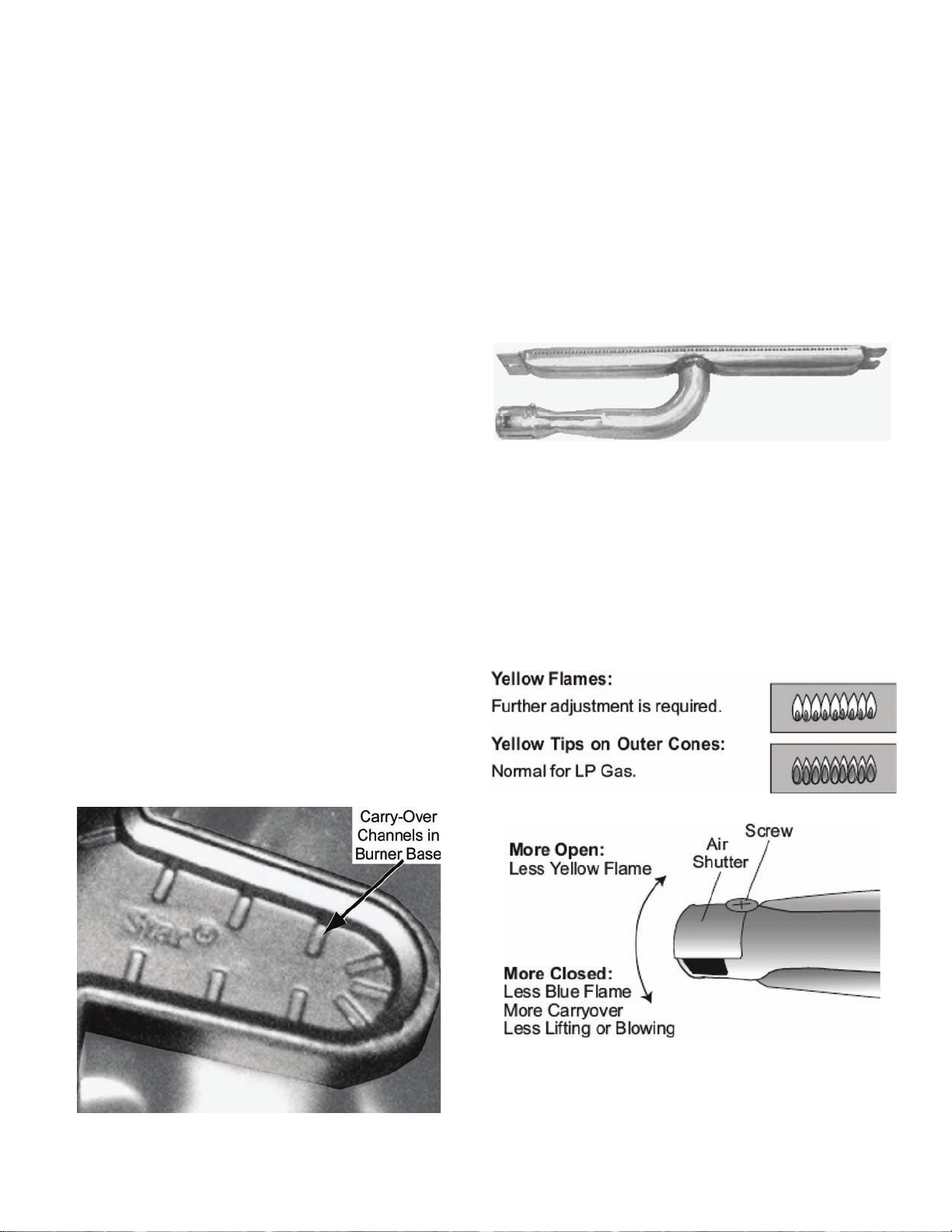
(LP) Gas. Orange-colored streaks in the flame are
produced from burning airborne debris; this is normal
during initial start up and should dissipate within a few
minutes of operation.
• Adjust the burner's control valve or thermostat to "LO"
or "SIM" to see that the flame continues to wrap around
the burner. Blow out the flame, or use a quick fan
motion from a writing tablet or piece of cardboard to
extinguish the flame, and then observe the burner's
ability to re-ignite and wrap around ("carry-over") the
burner within several seconds. The flame "carry-over"
is essential for proper burner ignition and re-ignition.
• Test re-ignition of the two Star
of the appliance by turning the control knobs to "XLO"
and observe the carry-over of the small simmer flames
as the XLO system cycles the two burners on and off.
• If the flame performance is not acceptable, verify that
the burner has the correct size LP orifice installed, and
that the regulator has been properly converted for LP
Gas.
• For un-acceptable performance of a Star
verify that the burner cap is seated properly in its
burner base. The cap should fit reasonably flat when
correctly-positioned in the base and not rock
significantly.
• If the burner flame is uneven, flutters, makes excessive
noise, or lifts, some of the ports in the burner cap may
be blocked with food spillage or other debris. Clogged
ports can be cleared using a straightened paper clip,
needle, or similar object. This is also applicable for
blocked ports in Grill or Griddle Burners.
• Additionally , hardened food spillage or other debris can
block some of the small carry-over channels in the
®
Star
Burner base, which can inhibit the flame from
wrapping around the burner. The channels can be
cleared using a wire brush.
®
Burners on the left side
®
Burner,
Tubular and wok burner performance and final air-shutter adjustments (if necessary)
Propane (LP) Gas is heavier, with greater density than
Natural Gas, and is distributed within the appliance at
higher pressure. The differences in properties an d
application cause LP Gas to entrain different amounts of
primary air which usually requires different air-sh utter
openings, as compared to Natural Gas applications for the
same or similar BTU ratings.
Burner for "solid plate" style Grill or Griddle
• A "too open" air shutter position creates noticeable
"lifting" (also called "blowing") of the flame - which can
degrade carry-over performance of the burner. This
condition can also create excessive noise.
• A flame that is "lazy", with excessively-long flames that
are reaching for air, is created by a "too closed" air
shutter. Many of the outer mantle s of the individual
flames tend to "coalesce" or blend together. Excessive
yellow color in the flame can also occur with an
excessively-closed shutter.
If air-shutter adjustment is needed, remove the burner from
the appliance. Loosen the shutter's retaining screw using a
1/4-inch nut driver or wrench and rotate the shutter to its
new position. If less than 50% opening is desired, move the
retaining screw to the alternate location shown on the next
page and rotate the shutter to its new position. Re-install
English 17
Page 20
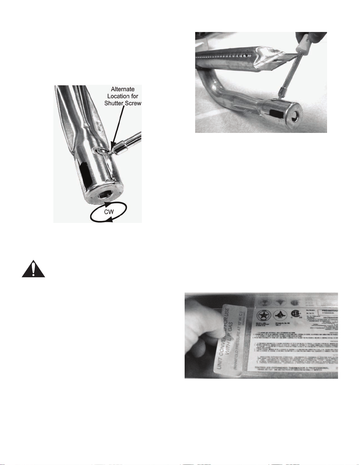
the burner and re-evaluate flame performance
characteristics. Repeat this process as necessary to
produce acceptable flame performance.
• For less than 50% air-shutter opening, move the
retaining screw to the alternate location and rotate the
air shutter in the clockwise (CW) direction as needed.
Final Step—Placement of LP Conversion Label
WARNING:
NEVER leave the gas conversion partially completed. If the appliance is operated while the gas conversion is
incomplete, high levels of carbon monoxide may be emitted, or a fire or explosion may occur.
IMPORTANT:
For proper identification and evidence of the appliance's
conversion to Propane (LP) Gas, affix the provided
Conversion Label in a location next to the Rating Labels on
the appliance. This is particularly important if the converted
appliance is re-installed in a different home.
English 18
Page 21

Location of Rating Labels on Thermador
®
Professional
Rating labels are found at various locations on the
appliances, depending upon the model series:
products
the range's lower front-frame, behind the kick-panel.
(See illustration below.)
• Pro Cooktops
the underside, chassis bottom of the cooktop, and can
be accessed inside the cabinet area, underneath the
unit.
• Pro-Grand Dual-Fuel Ranges
typically located behind the kick-panel, on the lower
cross member of the frame of the range.
• Pro-Harmony Dual-Fuel Ranges
typically located either under the front edge of rangetop
section or on a metal plate, attached with a lanyard to
— Rating labels are typically located on
— Rating labels are
— Rating labels are
English 19
Page 22

Table des matières
Sécurité . . . . . . . . . . . . . . . .1
Instructions de sécurité importantes . . 1
Instruction pour conversion 2
Avant de commencer . . . . . . . . . . . . . . . 2
Outils nécessaires pour conversion
des orifices : . . . . . . . . . . . . . . . . . . . . 2
Table 1: PLPKIT - nécessaire . . . . . . . 2
Table 2: tableau de conversion des orifices
LP --par numéro de modèle (anciens
modèles/nouveaux modèles) . . . . . . . 3
Remplacement des orifices de brûleurs sur
surfaces de cuisson et cuisinières . . . . 5
Remplacer les orifices de brûleur Star®–
tous les modèles . . . . . . . . . . . . . . . . . 5
Remplacer l’orifice de gril de gaz — si
équipé avec gril style grille ouverte . . . 6
Remplacer l’orifice de gril à gaz – si doté
du style plaque unie . . . . . . . . . . . . . . 7
Remplacer l’orifice de grille de gril –
si doté . . . . . . . . . . . . . . . . . . . . . . . . . 9
Remplacer l’orifice du wok — si équipé 10
Accès au régulateur de gaz . . . . . . . . . 11
Conversion du régulateur pour le
fonctionnement LP . . . . . . . . . . . . . . . . 12
Conversion du régulateur
Harper-Wyman . . . . . . . . . . . . . . . . . 12
Conversion du régulateur Maxitrol . . 13
Réglage des vis de soupape manuelle
pour brûleurs de surface de cuisson
et cuisinière . . . . . . . . . . . . . . . . . . . . . . 13
Tournevis pour régler la vis de
soupape . . . . . . . . . . . . . . . . . . . . . . 13
Cuisinière à combustion jumelé
PRO-GRAND™ et PRO-HARMONY™ et
surface de cuisson- Pro . . . . . . . . . . 14
Anciens modèles de cuisinière à
combustion jumelée et surface de
cuisson Professional® . . . . . . . . . . . . 14
Vérifier les fuites de gaz . . . . . . . . . . . 15
Vérifier les fuites de gaz avec une solution
liquide . . . . . . . . . . . . . . . . . . . . . . . . 15
Test et réglage des brûleurs . . . . . . . . 16
Vérifier la pression du distributeur
(au besoin) . . . . . . . . . . . . . . . . . . . . 16
Vérifier les caractéristiques de flamme
LP et rendement des brûleurs . . . . . . 16
Rendement du brûleur de wok et tubulure
et réglage final de l’obturateur d’air
(au besoin) . . . . . . . . . . . . . . . . . . . . 17
Étape finale – Pose de l’étiquette de
conversion LP . . . . . . . . . . . . . . . . . . . . 18
Emplacement de l’étiquette
signalétique sur les produits
Professional®Thermador . . . . . . . . . . 19
Cet appareil électroménager de Thermador est fait par
BSH Home Appliances Corporation
5551 McFadden Ave.
Huntington Beach, CA 92649
Questions ?
1-800-735-4328
www.thermador.com
Nous attendons de vos nouvelles !
Page 23

Sécurité
Instructions de sécurité importantes
LIRE LES INSTRUCTIONS AVANT DE COMMENCER
Nécessaire de conversion de gaz naturel à gaz
propane (LP) pour surfaces de cuisson et cuisinières à
®
combustion jumelée Thermador Professional
POUR L'USAGE RÉSIDENTIEL SEULEMENT
IMPORTANT :
Seul un technicien qualifié peut effectuer la conversion.
INSTALLATEUR :
Laisser les instructions de conversion avec l’appareil pour
le propriétaire.
PROPRIÉTAIRE :
Conserver ces instructions à des fins de références.
Comprend des orifices de brûleur Star
protecteurs pour une conversion appropriée en vue du
fonctionnement au gaz propane pour tous les brûleurs de
la surface de cuisson ou de la cuisinière des modèles de la
gamme suivante.
Conservez les pièces servant au gaz naturel pour une
future conversion de gaz LP au gaz naturel.
Ce nécessaire est utilisé pour convertir les surfaces de
cuisson Professional
PRO-GRAND™ et PRO-HARMONY™ Thermador pour un
fonctionnement du gaz naturel au gaz propane (LP). Ce
nécessaire ne peut pas être
anciens modèles de cuisinières ou surface de cuisson
Professional Thermador autres que ceux spécifiés dans
ces instructions (voir le TABLEAU 2). Ce nécessaire ne
peut pas être utilisé pour convertir les cuisinières, brûleurs
de four à gaz Professional
marque d’appareils.
®
, cuisinières à combustion jumelée
utilisé pour convertir les
®
Thermador ou tout autre
®
et orifices
AVERTISSEMENT :
Ce nécessaire de conversion doit
être effectué par un technicien
qualifié conformément aux
instructions du fabricant et à tous
les codes et exigences applicables
ayant juridiction. Si l’information
n’est pas observée à la lettre, il peut
en résulter un incendie, explosion
ou une production de monoxyde de
carbone causant ainsi des
dommages à la propriété, des
blessures ou même la mort.
L’agence de service est responsable
pour une installation appropriée de
ce nécessaire. L’installation n’est
pas appropriée ni complétée tant
que le fonctionnement de l’appareil
converti n’est pas vérifié tel qu’il est
indiqué dans les instructions
fournies avec le nécessaire.
ATTENTION :
Débrancher l’alimentation en gaz et électrique
avant d’effectuer la conversion. Avant de
remettre en circuit, s’assurer que tous les
contrôles sont en position arrêt (OFF).
À l’agence de service :
Il est important de savoir ce qui suit AVANT de commencer
la conversion de l’appareil.
• S’assurer qu’un système d’alimentation en gaz
propane (LP) est disponible et prêt à l’utilisation. Ceci
est particulièrement important avec les nouvelles
constructions.
• Il faut planifier suffisamment de temps et de ressources
afin d’effectuer adéquatement la conversion LP et la
compléter avant de quitter les lieux. Toutes les étapes
décrites dans ces instructions doivent être faites pour
convertir de façon sécuritaire l’appareil poru un
fonctionnement approprié au gaz propane. UNE
CONVERSION INCOMPLÈTE OU INADÉQUA TE DE
L’APPAREIL PEUT CRÉER UN RISQUE.
Français 1
Page 24

Avis de la Loi sur la toxicité et la potabilité de la Californie (proposition 65) :
AVERTISSEMENT :
Ce produit contient ou facilite l’émission, lors
d’une utilisation ordinaire pour laquelle il est
prévu, d’un ou de plusieurs produits chimiques
qui, selon les connaissances de l’État de la
Californie, peuvent causer le cancer et/o u des
anomalies congénitales ou d’autres problèmes
congénitaux. Pour minimiser toute exposition à
ces produits chimiques :
1. Effectuez la conversion au LP conformément aux instructions contenues dans le présent manuel.
2. Pour assurer une combustion adéquate, la conversion et l’ajustement des brûleurs devraient être réalisés par une agence ou un installateur accrédités.
3. Faites toujours fonctionner l’appareil conformément aux instructions fournies avec votre cuisinière ou votre surface de cuisson.
4. Lorsque vous cuisinez au gaz, assurez-vous de bien faire aérer la pièce en ouvrant une fenêtre ou en utilisant un ventilateur ou une hotte.
Instruction pour conversion
Avant de commencer
ATTENTION :
Avant de commencer la conversion, fermer
l’alimentation en gaz à l’appareil avant de
débrancher l’alimentation électrique.
Outils nécessaires pour conversion des orifices :
• Ciseaux.
• Tourne-écrou 7 mm.
• Douille profonde 1/2 po.
• Tourne-écrou 1/4 po ou clé.
• Tournevis à lame plate large 0,40 X 0,050 po.
• Tournevis à lame plate très large 0,60 X 0,060 po.
• Clé ou douille 7/8 po.
• Tournevis de précision à lame plate 1/8 X 0,020 po.
• Tournevis Phillips n° 2.
• Solution d’eau et savon ou conçue pour les fuites.
Tableau 1: PLPKIT - nécessaire
Description
Instructions PLPKIT 552805 1 Ruban mousse, 1 po 418145 1 Étiquette conversion au
propane Sac de plastique 418148 1 Orifice jet de brûleur
étoile
Orifice de gril (style grille
ouverte)
Orifice de gril (style
plaque unie) Orifice protecteur de grille 418150 1 Orfice protecteur de wok 414918 1 Ce nécessaire de conversion au propane comprend les
quantités de piéces indiquées ci-dessus. Toutefois,
certaines piéces ne seront pas utilisées selon le type et
le modéle de l’appareil à convertir. Consulter le
TABLEAU 2 pour une liste de combinaison d’orifices
appropriée à utiliser pour un modéle particulier.
Numéro
Service
418146 1
424851 6
418151 1
414916 1
Quantité
Français 2
Page 25

ATTENTION :
Au moment de brancher l’appareil sur le gaz,
s’assurer que le réservoir de gaz propane est
doté de son propre régulateur de pression
élevée. La pression maximale de gaz à cet
appareil ne doit pas excéder 14,0 po, C.E. du
régulateur du réservoir de gaz propane.
Lorsque converti adéquatement en utilisant les orifices LP
indiqués, les brûleurs fonctionneront au débit suivant avec
le gaz propane (LP) :
• Brûleurs Star
avec orifices 1,07 mm.
• Gril à gaz (style grille ouverte) — 17 000 BTu/h [4.98
kW], avec orifice 1,20 mm.
• Gril à gaz (style plaque unie) — 12 000 BTu/h [3.51
kW], avec orifice n° 59.
• Grille à gaz — 13 000 BTu/h [3.81 kW], avec orifice n°
57 – ou – 1,10 mm.
Tableau 2: tableau de conversion des orifices LP --par numéro de modèle (anciens modèles/nouveaux modèles)
®
— 13 000 BTu/h [3.81 kW] chacun,
• Wok à gaz — 24 500 BTu/h [7.17 kW], avec orifice n°
54 – ou – 1,40 mm.
AVERTISSEMENT :
NE JAMAIS laisser la conversion incomplète. Si
l’appareil est actionné lorsque la conversion est
incomplète, il y a risque d’émission élevée de
monoxyde de carbone, d’incendie ou
d’explosion.
AVERTISSEMENT :
Si les orifices pour gaz naturel sont laissés en
place pendant que l’on tente de faire foncti onner
l’appareil avec le gaz propane, à un réglage de
pression élevé pour gaz LP, les brûleurs
produiront une flamme plus grosse ce qui peut
émettre des niveaux élevés de monoxyde de
carbone dans la pièce, causer un incendie ou
une explosion.
Appareil
Numèro de modèle
(ancien/nouveau)
Surfaces de cuisson Pro :
PC304 / PCG304E 4 chac - 1.07mm
PC366 / PCG366E 6 chac - 1.07mm
PC364GD / (aucun nouveau) 4 chac - 1.07mm #57 -ou- 1.10mm
PC364GE / PCG364ED 4 chac - 1.07mm
PC364GL / PCG364EL 4 chac - 1.07mm 1.20mm (grille) ou 59
PC486GD / (aucun nouveau) 6 chac - 1.07mm #57 -ou- 1.10mm
PC486GE / PCG486ED 6 chac - 1.07mm
PC486GL / PCG486EL 6 chac - 1.07mm 1.20mm (grille) ou 59
PC484GG / (aucun nouveau) 4 chac - 1.07mm 1.20mm (grille
PC484GGE / PCG484EC 4 chac - 1.07mm 1.20mm (grille) ou 59
PC484WK / PCG484EW 4 chac - 1.07mm 54 -ou- 1.40mm PC484GE / PCD484EE 4 chac - 1.07mm
Cuisinières à combustion jumelèe PRO-GRAND
Brûleur Star
424851
Orifice
MC
(27 po de profondeur) :
Gril à gaz*
(style grille/plaque)
418151 -ou- 414916
Orifice protecteur
(plaque)
(plaque)
ouverte seul.)
(plaque)
Gril à gaz**
418150
Orifice
protecteur
#57 -ou- 1.10mm
Wok à gaz
414918
Orifice
protecteur
PD304 / PRD304EG 4 chac - 1.07mm
PD366 / PRD366EG et
PRD366EPG
6 chac - 1.07mm
Français 3
Page 26

Tableau 2: tableau de conversion des orifices LP --par numéro de modèle (anciens modèles/nouveaux modèles)
Appareil
Numèro de modèle
(ancien/nouveau)
Brûleur Star
424851
Orifice
Gril à gaz*
(style grille/plaque)
418151 -ou- 414916
Orifice protecteur
Gril à gaz**
418150
Orifice
protecteur
PD364GD / (aucun nouveau) 4 chac - 1.07mm 57 -ou- 1.10mm PD364GE / PRD364EDG et
4 chac - 1.07mm
PRD364EDPG
PD364GL / PRD364ELG 4 chac - 1.07mm 1.20mm (grille) ou 59
(plaque) PD486GD / (aucun nouveau) 6 chac - 1.07mm 57 -ou- 1.10mm PD486GE / PRD486EDG et
6 chac - 1.07mm
PRD486EDPG
PD486GL / PRD486ELG 6 chac - 1.07mm 1.20mm (grille) ou 59
(plaque)
PD484GG / (aucun nouveau) 4 chac - 1.07mm 1.20mm (grille
57 -ou- 1.10mm
ouverte seul)
PD484GGE / PRD484ECG 4 chac - 1.07mm 1.20mm (grille) ou 59
(plaque) PD484GE / PRD484EEG 4 chac - 1.07mm
Cuisinières à combustion jumelèe PRO-HARMONY
MC
(24 po de profondeur) :
Wok à gaz
414918
Orifice
protecteur
DP304 / PRD304EH 4 chac - 1.07mm
DP366 / PRD366EH 6 chac - 1.07mm
DP364GE / PRD364EDH 4 chac - 1.07mm
DP364GL / PRD364ELH 4 chac - 1.07mm 59 (plaque unie
seul.)
(aucun ancien) / PRD486EDH 6 chac - 1.07mm
(aucun ancien) / PRD486ELH 6 chac - 1.07mm 59 (plaque unie
seul.)
(aucun ancien) / PRD484ECH 4 chac - 1.07mm 59 (plaque unie
seul.)
(aucun ancien) / PRD484EEH 4 chac - 1.07mm
REMARQUES :
* Certains nouveaux modéles de surfaces de cuisson Pro et cuisiniéres à combustion jumelée Pro-Grand ont le style
gril à gaz ouvert..
** Les modéles plus anciens avec les lettres <<GE>> et les nouveaux modéles <<E>> dotés des lettres <<ED>>,
<<EC>> ou <<EE>> sont pour les modéles avec grille électrique - aucune conversion nécessaire
Exemples
Haute altitude:
Plusieurs appareils Thermador doté du nécessaire de
conversion au gaz propane (LP) sont certifiés ACNOR pour
un fonctionnement sécuritaire jusqu’à une élévation de 10
200 pi (3 109 m) au-dessus du niveau de la mer, sans autre
: "PC484GGE", "DP364GE", "PRD364EDG", "PRD484ECH", or "PCD484EE".
appareil utilisé à une altitude plus élevée, consulter la
compagnie de gaz locale relativement à leurs
recommandations pour la dimension appropriée de l’orifice
et tout autre réglage nécessaire afin d’obtenir une
combustion appropriée du gaz à une altitude élevée.
modification. Pour une conversion LP sécuritaire d’un
Français 4
Page 27

Remplacement des orifices de brûleurs sur surfaces de cuisson et cuisinières
Important :
Après le remplacement de chaque orifice et avant de
réassembler le brûleur , effectuer une vérification de fu ite de
gaz de l’orifice et des raccords associés, selon Vérification
des fuites de gaz donnée dans ces instructions.
Remplacer les orifices de brûleur Star®– tous les modèles
• Couper une pièce d’adhésif mousse de 3/8 po de long
fournie dans le nécessaire et placer sur le bord du
tourne-écrou utilisé pour remplacer les orifices de
brûleur Star, comme montré.
• Utiliser un écrou 7 mm pour se passer par le venturi et
enlever l’orifice du porte-jet du brûleur.
• Remplacer chaque orifice de brûleur avec un jet LP
1,07 mm fourni avec le nécessaire. C’est la dimension
pour les brûleurs Star pour produire un dé bit de 13 000
BTu/h [3,81 kW] avec le gaz propane LP.
Bande mousse
La mousse aide à maintenir l’orifice dans l’extrémité du
tourne-écrou pour ne pas qu’il tombe dans l’appareil
pendant l’installation ou le retrait.
• Effectuer un bref test de fuite pour chaque orifice et
raccords associés, selon Vérification des fuites donnée
dans les instructions. Un accès approprié au porte-jet
de brûleur peut être fait après le retra it du plateau
égouttoir – voir Accès au régulateur de gaz pour le
retrait du plateau égouttoir.
Français 5
Page 28

• Chaque orifice porte la marque «107» (pour le
diamètre de 1,07 mm diamètre), comme montré.
Remplacer l’orifice de gril de gaz — si équipé avec gril style grille ouverte
Ce modèle est de style grille ouverte pouvant être identifié
par un brûleur tubulaire en U et déflecteur de chaleur
ondulé, comme montré.
AVERTISSEMENT
Le gril doit être assemblé comme montré.
L’écran d e ch aleur du platea u ég outtoir doit ê tre
en place et le brûleur doit être bien positionné
relativement à l’alimentation en gaz. Un
assemblage incorrect peut causer un risque
pendant le fonctionnement.
• Retirer la grille, le radiant et le brûleur de l’assemblage
du réservoir de gril
• Tirer le levier en métal sur le devant du brûleur de gril
pour le dégager, puis retirer le brûleur de gril.
• Utiliser une douille 1/2 po de profondeur pour enlever
l’orifice protecteur du gril et remplacer avec un orifice
LP 1,20 mm fourni avec le nécessaire.
• Prérégler le volet d’air du brûleur à approximativement
75 % fermé (ouverture approximative de 0,20 po) et
serrer la vis avec un tourne-écrou ou une clé1/4 po.
• Réinsérer l’extrémité du venturi du brûleur de gril sur
les deux fentes à l’arrière de l’assemblage de réservoir
de gril, comme montré ci-dessous. Tourner ensuite
l’autre extrémité du brûleur en position et verrouiller la
languette sur le devant du brûleur dans la fente du
déflecteur de chaleur.
• Réinstaller le radiant en acier inoxydable sur les deux
tiges de chaque côté de l’assemblage de réservoir de
gril.
Français 6
Page 29

• Remettre la grille de façon à ce que le rail pour
surélever les aliments soit orienté ver l’arrière du gril.
• L’orifice protecteur marqué 1,20 mm est conçu pour
produire 17 000 BTu/h [4.98 kW], avec gaz propane
(LP).
Remplacer l’orifice de gril à gaz – si doté du style plaque unie
Ce style peut être identifié par sa plaque de gril côtelée et
son brûleur tubulaire en T, comme montré.
• Après la conversion d’orifice, vérifier les fuites de gaz
et réinstaller le brûleur de gril, vérifier que l’espace
d’électrode et fixation au brûleur est selon la distance
montrée ici.
• Vérifier si le volet d’air du brûleur de gril est bien réglé,
selon Test et réglage du brûleur dans ces instructions,
car la position du volet d’air peut aussi modifier le
rendement de l’allumage.
• Retirer la plaque de gril. Certains modèles ont une
plaque et un cadre en deux pièces, semblable au
modèle de la page suivante.
Français 7
Page 30

• Enlever les vis à chaque extrémité de la cannelure de
flamme, incliner vers soi et tirer la cannelure hors de la
fente avant dans le réservoir de gril.
• Utiliser une douille 1/2 po de profondeur pour enlever
l’orifice protecteur de gril.
• L’orifice LP est étampé 59, format produisant 12 000
BTu/h [3,51 kW], avec le gaz propane.
• Régler le voleur d’air du brûleur à approximativement
75 % fermé (environ 0,20 po d’ouverture) et serrer la
vis avec un tourne-écrou ou une clé 1/4 po.
• Après la conversion, vérifier les fuites de gaz et régler
le brûleur de gril, vérifier si l’espace de l’allumeur de
surface chaude (HSI) est selon la distance montrée,
pour les deux types d’allumeurs suivants utilisés avec
les modèles gril.
Français 8
Page 31

Remplacer l’orifice de grille de gril – si doté
• L’orifice LP porte le n° 57 ce qui est la dimension pour
produire 13 000 BTu/h. [3,81 kW], en utilisant le gaz
propane (LP). L’orifice peut aussi être de 1,10 mm de
diamètre; dans quel cas, l’orifice protecteur doit porter
la marque «110» ou «1,10 mm».
• Prérégler le volet d’air du brûleur à approximativement
75 % fermé (environ 0,20 po ouvert) et serrer la vis à
l’aide d’un écrou ou d’une clé de 1/4 po.
• Retirer le plateau égouttoir de grille, la plaque et le
cadre. Ces pièces ne sont pas maintenues, elles
s’enlèvent facilement.
• Enlever les vis de chaque côté de la cannelure de
flamme tout en portant attention à ne pas échapper les
entretoises à l’intérieur de l’appareil.
• Enlever la plaque couvercle avec 4 vis, la quelle couvre
le venture du brûleur de grille au fond du réservoir de
grille.
• Soulever le brûleur de grille.
• Utiliser une douille 1/2 po de profondeur pour enlever
l’orifice de grille. Au moment d’installer l’orifice LP, faire
très attention à ne pas plier la fixation d’orifice en
métal.
• Après la conversion, vérifier les fuites de gaz et
réinstaller le brûleur de grille, vérifier si l’espace de la
pointe de l’électrode d’allumeur à la surface du brûleur
(point tangent) est d’environ 0,105 po. Il y a un peu de
mouvement disponible dans la fixation du brûleur, à
chaque extrémité pour régler l’espacement au besoin.
Français 9
Page 32

Remplacer l’orifice du wok — si équipé
• Enlever les 2 vis qui maintiennent la veilleuse du
brûleur de la fixation sur l’assemblage du support
supérieur du wok.
• Soulever droit l’assemblage, de quelques pouces du
châssis de wok et enlever le brûleur de wok.
• Retirer l’assemblage supérieur de wok. Ceci expose la
soupape de sécurité.
Soupape de sécurité de wok avec or if ic e
• L’orifice LP porte le n° 54 ce qui est la dimension pour
porduire 24 500 BTu/h. [7,17 kW], en utilisant le gaz
propane (LP). L’orifice peut aussi être de 1,40 mm de
diamètre; dans quel cas, l’orifice protecteur doit porter
la marque «140» ou «1,40 mm».
• Utiliser une douille 1/2 po de profondeur pour enlever
l’orifice protecteur de la soupape de sécurité.
REMARQUE :
La veilleuse de brûleur ne requiert pas une conversion pour
fonctionnement avec le gaz propane.
• Prérégler le volet d’air sur le brûleur de wok en position
complètement ouverte.
• Remettre l’assemblage supérieur de wok.
• Réinstaller le brûleur de wok. S’assurer que le venturi
du brûleur est adéquatement positionné sur l’orifice
protecteur et que le bas de la tête du brûleur est
positionné entre les tiges sur la croix à la base du
support supérieur.
• Fixer la veilleuse de brûleur sur la fixation du support
supérieur de wok.
Français 10
Page 33

Accès au régulateur de gaz
Tous les modèles à combustion jumelée et certaines
surfaces de cuisson sont dotés d’un régulateur de gaz situé
à l’intérieur de l’appareil, sous le plateau égouttoir gauche.
• Régulateur de gaz situé à l’intérieur, côté gauche.
• Retirer les grilles de cuisson.
• Retirer le capuchon de brûleur Star
leégouttoir venturi des 2 brûleurs avec une clé ou
douille 13/16 po.
• Débrancher le fil d’étincelle de la languette sur
l’électrode d’étincelle pour chaque brûleur.
®
, puis enlever
• Retirer la garniture aluminium des côtés du plateau.
• Enlever l’écran sur certains modèles. Certains modèles
ont un écran double qui va jusqu’en dessous du
plateau égouttoir.
Français 11
Page 34

• Le régulateur de gaz est situé près du coin arrière
gauche à l’intérieur de l’appareil.
REMARQUE :
Un orifice de brûleur étoile tombé lors du remplacement
peut être récupéré à cette étape.
Conversion du régulateur pour le fonctionnement LP
AVERTISSEMENT :
Si les orifices pour gaz nature l sont en pla ce pendan t le fonctionne ment de l’appareil avec du gaz propane ( LP),
à un réglage de pression élevée pour le gaz LP, les brûleurs produiront une grosse flamme ce qui peut émettre
des niveaux élevés de monoxyde de carbone dans la pièce, un incendie ou une explosion. Tous les
remplacements des orifices pour le fonctionnement au gaz LP doivent être faits avant la conversion du
régulateur.
Harper-Wyman et Maxitrol sont les deux marques de régulateurs de gaz utilisés avec les produits Professional
Thermador.
Conversion du régulateur Harper-Wyman
• Utiliser un tournevis à lame plate large 0,40 X 0,050
po, pour enlever le capuchon de conversion.
• Avec le tournevis large, presser sur le capuchon de
conversion et tourner dans le sens contre horaire pour
dégager la base baïonnette.
• Retourner le capuchon, côté creux sur le dessus. «LP»
figure au fond du capuchon.
• Utiliser un tournevis à lame plate très large 0.60 X
0,060 po, pour réinstaller le capuchon.
®
Français 12
Page 35

• Remettre le capuchon sur le régulateur avec le creux
sur le dessus, «LP» est visible. Presser vers le bas et
tourner dans le sens horaire pour verrouiller le
capuchon en place.
Conversion du régulateur Maxitrol
• Enlever le capuchon de conversion avec une douille ou
une clé 7/8 po.
• Dégager la tige du bas du capuchon, retourner la tige
pour voir l’extrémité «LP» et réenclencher la tige dans
le capuchon, comme montré.
Retourner la tige
• Réinstaller le capuchon de conversion, configuré pour
le gaz LP, dans le régulateur Maxitrol
Réglage des vis de soupape manuelle pour brûleurs de surface de cuisson et cuisinière
Tournevis pour régler la vis de soupape
Un tournevis de précision à lame robuste, semblable au
*Wiha n° 26033, avec lame 1/8 po [3,0 mm] de large, 0 ,020
po [0,50 mm] d’épaisseur, comme ci-dessous, doit être
utilisé pour repositionner les vis de dérivation pour un
réglage de débit minimal sur les soupapes manuelles.
*Utilisé avec la permission de Wiha Quality Tools, une division
de Willi Hahn Corporation, É.-U.
Français 13
Page 36

Cuisinière à combustion jumelé PROGRAND™ et PRO-HARMONY™ et
surface de cuisson- Pro
• Enlever le bouton de la tige de soupape en tirant droit
lentement, hors du panneau de contrôle.
• Tourner la vis de soupape dans le sens horaire jusqu’à
ce que la position «bas» soit atteinte. NE PAS trop
serrer la vis de soupape.
• Pour les soupapes de gril à grille ouverte ou de wok –
après avoir tourner la vis de soupape vers le bas,
tourner la vis dans le sens contre horaire un demi (1/2 )
tour.
REMARQUES :
• Il est nécessaire que les deux soupapes pour XLO (les
plus à gauche sur le panneau de contrôle) soient en
position arrêt (OFF) pour un accès approprié aux vis
de soupape par les trous de dégagement dans le
potentiomètre XLO.
• Le gril à gaz de style plaque unie et la grille à gaz sont
contrôlés par thermostat et ne requièrent pas de
réglage de soupape.
• Pour les nouveaux modèles, enlever la vis de bague
de fixation située à la droite de la tige de soupape.
• Pour la vis de soupape, insérer le tournevis de
précision dans le trou de la bague créé en enlevant la
vis de fixation.
Anciens modèles de cuisinière à
combustion jumelée et surface de cuisson
Professional
• Enlever le bouton de la tige de soupape en tirant droit
lentement, hors du panneau de contrôle.
• Les vis de soupape sur les modèles plus anciens
peuvent être accédées directement par le panneau de
contrôle, sans retirer les vis de bague.
®
Français 14
Page 37

Vérifier les fuites de gaz
AVERTISSEMENT :
NE PAS utiliser de flamme pour vérifier les fuites de gaz.
AVERTISSEMENT :
L’allumeur d e surface chaude (HSI) pour le gril devient très chaud et peut causer des brûlures graves.
Vérifier les fuites de gaz avec une solution liquide
Tous les remplacements d’orifices du nécessaire de
conversion PLPKIT pour le gaz LP sont dotés de filetage
droit (non comme un tuyau) et ne requièrent pas de
scellant à filetage.
La vérification de fuites doit être faite une fois la conversion
des orifices complétée et avant que les brûleurs ne soient
réassemblés et testés.
• S’assurer que tous les orifices LP sont bien serrés et
que toutes les soupapes et contrôles sont en position
OFF.
• Mettre en circuit les alimentations électrique et de gaz.
• Évaluer brièvement la connexion filetée de chaque
orifice remplacé, un à la fois.
• Vaporiser une généreuse quantité de solution eau et
savon ou une solution conçue pour vérifier les fuites de
gaz sur les connexions filetées à la base de l’orifice.
Éviter de vaporiser les dispositifs électriques. (Une
solution d’eau et de savon pour la vaisselle, 25 %, est
efficace pour cette marche à suivre.)
• Mettre en circuit brièvement la soupape ou le contrôle
tout en bloquant le trou d’orifice avec une efface
souple, le doigt ou un objet semblable. Il est normal
d’entendre un bruit d’allumage pendant ce processus. -
--Éviter la chaleur extrême du gril HIS sur les modèles
qui en sont dotés. Voir l’avertissement ci-dessus. ---
• Surveiller la base de l’orifice pour voir s’il y a des bulles
qui se forment autour de la connexion filetée.
• Une formation de bulle indique une fuite de gaz. La
grosseur et la quantité de bulles représentent une
indication de la sévérité de la fuite.
• Réparer immédiatement toute fuite de gaz. Ceci peut
être effectué en serrant l’orifice.
• Puisqu’une force considérable est utilisée parfois
pendant le remplacement d’orifices, vérifier les fuites
de gaz aux autres raccords menant à l’orifice.
• Fermer les alimentations en électricité et en gaz.
• Réassembler l’appareil en vue d’un test des systèmes
de brûleurs nouvellement convertis.
Français 15
Page 38

Test et réglage des brûleurs
Vérifier la pression du distributeur (au besoin)
La vérification de la pression du distributeur de l’appareil
N’EST P AS nécessaire pour la conversion au gaz propane.
Toutefois, si la pression à la sortie du régulateur de ga z ou
la pression d’entrée à l’appareil semble suspecte, ef fectuer
les étapes suivantes pour vérifier la pression du
distributeur.
• La mesure de pression du distributeur peut être
obtenue à un des orifices de brûleurs étoile, comme
montré.
Vérifier les caractéristiques de flamme LP et rendement des brûleurs
Pour observer la flamme, desserrer ou enlever le nombre
minimum de pièces nécessaires pour une vue non
obstruée. Il peut être nécessaire de fermer les éclairages
ou les stores de fenêtres pour assombrir la pièce et faciliter
la vérification.
• Vérifier l’allumage du brûleur. Pousser le bouton de
contrôle du brûleur et tourner dans le sens contre
horaire à HI. L’électrode d’allumage et le module
d’étincelle produisent un clic. Une fois l’air purgé de la
canalisation, le brûleur devrait s’allumer dans un délai
de 4 secondes.
• Fixer un manomètre portatif qui lit la pression en
pouces par colonne d’eau en utilisant un tube en vinyle
ou en PVC.
• Ouvrir les alimentations électrique et de gaz à
l’appareil.
• Ouvrir un des brûleurs de surface en position HI. Ceci
est important pour obtenir une lecture de pression
véritable dans des conditions de débit de gaz.
• Ouvrir la soupape manuelle pour le brûleur en q uestion
en position HI. (Il y aura un bruit d’allumage provenant
de ce brûleur.)
• La pression du distributeur sur le manomètre doit être
entre 9,50 et 10,50 po C.E. pour le régulateur converti
au gaz LP.
• Si la pression du distributeur est inférieure à cette
gamme, vérifier si le régulateur a été adéquatement
converti pour le gaz LP et que la pression d’entrée à
l’appareil est entre 11,0 et 14,0 po C.E.
• La flamme LP devrait être stable, sans bruit excessif.
Le cône intérieur de chaque flamme doit être bien
défini et distinct des uns des autres
• La portion de la flamme le long du brûleur ne doit pas
être excessive ni soulevée ou couchée.
Français 16
Page 39

• Il est normal d’avoir une pointe jaune qui apparaît
après quelques minutes d’utilisation. Des rayures
orangées dans la flamme sont produites par les débris
dans l’air; ceci est normal pendant la mise en marche
initiale et devrait se dissiper après quelques minutes.
• Régler la soupape de contrôle du brûleur ou le
thermostat à LO ou SIM pour voir si la flamme continue
d’envelopper le brûleur. Souffler la flamme ou utiliser
un mouvement de vent avec une tablette pour éteindre
la flamme, puis observer si le brûleur est apte à
réallumer et si la flamme enveloppe le brûleur en
quelques secondes. La flamme enveloppante est
essentielle pour un allumage et un rallumage du
brûleur.
• Vérifier le rallumage des deux brûleurs étoiles sur le
côté gauche de l’appareil en tournant les boutons de
contrôle à XLO et observer si la petite flamme pour
mijoter enveloppe le brûleur pendant le cycle XLO des
deux brûleurs.
• Si le rendement de la flamme n’est pas acceptable,
vérifier si le brûleur est doté du format approprié
d’orifice LP et que le régulateur a été adéquatement
converti pour le gaz LP.
• Pour un rendement inacceptable du brûleur étoile,
s’assurer que le capuchon du brûleur est bien en
place. Le capuchon doit s’ajuster à plat lorsque bien
positionné à la base et ne pas ballotter trop.
• Si la flamme du brûleur n’est pas uniforme, qu’elle
vacille, fait du bruit ou se soulève, certains ports du
brûleur peuvent être obstrués. Les nettoyer à l’aide
d’un trombone étiré, une aiguille ou objet semblable.
Ceci s’applique également aux ports obstrués des
brûleurs de gril ou de grille.
• Également, des déversements d’aliments ou autres
peuvent obstruer certains des petits canaux à la base
du brûleur étoile, ce qui peut empêcher la flamme de
bien envelopper le brûleur. Nettoyer les canaux avec
une brosse métallique.
Rendement du brûleur de wok et tubulure et réglage final de l’obturateur d’air (au besoin)
Le gaz propane (LP) est plus lourd avec une plus grande
densité que le gaz naturel et est distribué dans l’appareil à
une pression plus élevée. Les différences dans les
propriétés et les applications font que le gaz LP entraîne
une quantité différente d’air primaire lequel requiert
habituellement différentes ouvertures d’obturateur d’air,
comparativement aux applications du gaz naturel pour la
même cote en BTu.
Brûleur pour gril de style plaque uni ou brûleur de grille
• Une position d’obturateur d’air trop ouverte peut créer
un soulèvement notable de la flamme, ce qui dégrade
le rendement enveloppant du brûleur. Cette condition
peut causer aussi du bruit excessif.
• Une flamme dite paresseuse est une flamme
excessivement longue qui recherche l’air et qui est
créée par un obturateur d’air trop fermé. Plusieurs
manteaux extérieurs de chaque flamme tendent à se
mettre ensemble. Une couleur jaune excessive de la
flamme survient lorsque l’obturateur est trop fermé.
Si un réglage de l’obturateur d’air est requis, enlever le
brûleur de l’appareil. Desserrer la vis qui maintient
l’obturateur avec une douille ou une clé 1/4 po et tourner
Français 17
Page 40

l’obturateur à sa nouvelle position. Si une ouverture de
moins de 50 % est désirée, déplacer la vis de retenue
comme montré ci-dessous et tourner l’obturateur à sa
nouvelle position. Réinstaller le brûleur et évaluer de
nouveau les caractéristiques de rendement. Répéter au
besoin pour un rendement adéquat.
• Pour une ouverture de moins de 50 %, déplacer la vis
de retenue à une autre position et tourner l’obturateur
d’air dans le sens horaire au besoin.
Étape finale – Pose de l’étiquette de conversion LP
AVERTISSEMENT :
NE JAMAIS laisser la conversion de gaz partiellement terminée. Si l’appareil est actionné pendant une
conversion incomplète, il y aura de hauts niveaux d’émission de monoxyde de carbone, un risque d’incendie ou
d’explosion.
IMPORTANT :
Pour une identification adéquate et une mise en évidence
de la conversion de l’appareil au gaz propane (LP),
apposer l’étiquette de conversion fournie à côté des
étiquettes signalétiques sur l’appareil. Ceci est
particulièrement important si l’appareil conve rti est
réinstallé dans une nouvelle maison.
Français 18
Page 41

Emplacement de l’étiquette signalétique
®
sur les produits Professional
Les étiquettes signalétiques sont situées à différents
endroits sur les appareils, selon les modèles :
Thermador
plaque en métal fixée au cadre avant inférieur de
l’appareil, derrière la plaque inférieure (voir illustration).
• Surface de cuisson Pro
sont habituellement situées sur le dessous, au bas du
boîtier de la surface de cuisson et peut être accédée
par l’intérieur, sous l’appareil.
• Cuisinière à combustion jumelée Pro- Gr an d
étiquettes signalétiques sont habituellement situées
derrière la plaque inférieure, sur la traverse inférieure
du cadre de l’appareil.
• Cuisinière à combustion jumelée Pro- Ha rm on y
étiquettes signalétiques sont habituellement situées
sous le bord avant de la section cuisinière ou sur la
– les étiquettes signalétiques
– les
– les
Français 19
Page 42

Table des matières
Seguridad . . . . . . . . . . . . . . .1
Instrucciones Importantes de Seguridad 1
Instrucciones de conversión 2
Antes de comenzar . . . . . . . . . . . . . . . . 2
Posibles Herramientas Necesarias para
Todas las Conversiones de Orificio: . . 2
Table 1: Contenido del Kit de
Conversión . . . . . . . . . . . . . . . . . . . . . 2
Table 2: Tabla de Conversión de Orificio —
por Número de Modelo (modelos anteri-
ores / modelos nuevos) . . . . . . . . . . . . 3
Reemplazando los Orificios de
Quemadores en Parrillas / Estufas . . . . 5
Reemplace los orificios del Quemador
Star® – todos los modelos . . . . . . . . . 5
Reemplace el Orificio de la Parrilla –
si está equipado con parrilla estilo
rejilla-abierta . . . . . . . . . . . . . . . . . . . . 6
Reemplace el Orificio de Gas de la
Parrilla – si está equipada con Parrilla
Estilo Placa-Sólida . . . . . . . . . . . . . . . 7
Reemplace el Orificio de la Plancha de
Gas – si así está equipada . . . . . . . . . 9
Reemplace el Orificio de Wok en la
Pro Cooktop – si así está equipada . 10
Accediendo el Regulador de Gas . . . . 11
Convirtiendo el Regulador a Operación
con LP . . . . . . . . . . . . . . . . . . . . . . . . . . 13
Conversión de reguladores
Harper-Wyman . . . . . . . . . . . . . . . . . 13
Conversión de reguladores Maxitrol . 13
Estableciendo Tornillos de Válvula
Manualmente para Quemadores de
Parrillas/Estufas . . . . . . . . . . . . . . . . . . 14
Desarmador para establecer el tornillo
de válvula . . . . . . . . . . . . . . . . . . . . . 14
Estufas y Parrillas PRO-GRAND™ y
PRO-HARMONY™ de Combustible
Dual . . . . . . . . . . . . . . . . . . . . . . . . . . 14
Modelos anteriores de Estufas y Parrillas
Professional® de combustible dual . . 15
Comprobación de Fugas de Gas . . . . 16
Comprobación de Fugas de Gas utilizando
una solución líquida . . . . . . . . . . . . . 16
Prueba y ajuste de Quemador . . . . . . . 17
Verificando la presión del múltiple
(si es necesario) . . . . . . . . . . . . . . . . 17
Verificando las características de flama del
LP y el desempeño de quemadores . 17
Desempeño de quemador tubular y
de wok y ajustes al abturador de aire
(si es necesario) . . . . . . . . . . . . . . . . 18
Paso Final – Colocación de la Etiqueta de
Conversión a LP . . . . . . . . . . . . . . . . . . 20
Ubicación de las Etiquetas de
Especificaciones en productos
Thermador Professional
®
. . . . . . . . . 20
Cet appareil électroménager de Thermador est fait par
BSH Home Appliances Corporation
5551 McFadden Ave.
Huntington Beach, CA 92649
Questions ?
1-800-735-4328
www.thermador.com
Nous attendons de vos nouvelles !
Page 43

Seguridad
Instrucciones Importantes de Seguridad
POR FAVOR LEA EL INSTRUCTIVO COMPLETO ANTES DE PROCEDER
Kit de Conversión de Gas Natural a Propano (LP) para
®
Parrillas Thermador Professional
Combustible Dual
PARA EL USO RESIDENCIAL SOLAMENTE
IMPORTANTE:
Solo técnicos de servicio o instaladores calificados o
deben realizar la conversión.
INSTALADOR:
Por favor deje estas Instrucciones de Conversión junto a la
unidad con el dueño.
DUEÑO:
Por favor conserve estas instrucciones para referencia
futura.
Contiene orificios de Quemador Star
campana para la propia conversión a operación con Gas
Propano para todos los quemadores en la sección de
parrilla o plancha de las series de modelos siguientes.
Conserve las piezas de gas natural para una posible
conversión de gas LP a gas natural en el futuro.
y Estufas de
®
y orificios de
ADVERTENCIA:
Este kit de conversión debe ser
instalado por una agencia de
servicio calificada de acuerdo con
las instrucciones del fabricante y
todos los códigos aplicables y
requerimientos de las autoridades
que tengan jurisdicción. Si la
información de estas instrucciones
no es seguida exactamente puede
surgir fuego, explosión o producción
de monóxido de carbono causando
daños a propiedad, lesiones
personales o la muerte. La agencia
de servicio calificada es responsable
por la instalación apropiada de este
kit. La instalación no es apropiada o
completa hasta la operación de la
unidad convertida es verificada
como se especifica en las
instrucciones del fabricante
proveídas con el kit.
Al Agente de Servicio:
Es importante que conozca lo siguiente ANTES de
comenzar la conversión de gas de la unidad.
Este kit es utilizado para convertir Planchas Thermador
Professional
Dual, y PRO-HARMONY™ Estufas de Combustible Dual,
de operación con gas natural a Gas (LP). Este kit no puede
ser utilizado para convertir modelos anteriores de parrillas
o estufas Thermador Professional distintas a los indicados
en estas instrucciones (vea TABLA 2). Este kit no puede
ser utilizado para convertir Estufas de Todo Gas
Thermador Professional
cualquier otra unidad de otra marca.
®
, PRO-GRAND™ Estufas de Combustible
®
, quemadores de horno, o
PRECAUCIÓN:
Desconecte el gas y corriente eléctrica antes de
realizar la conversión. Antes de encender la
corriente, asegúrese que todos los controles
están en posición de APAGADO.
• Confirme que el sistema de suministro de Gas
Propano (LP) está disponible y listo para utilizarse.
Esto es particularmente importante para
construcciones nuevas.
• Debe planear para tener suficiente tiempo y recursos
para realizar el proceso de conversión a LP
apropiadamente –y- completamente antes de
abandonar el sitio de trabajo. Cada paso descrito en
estas instrucciones debe ser realizado para convertir
con seguridad la unidad para una operación apropiad a
con Gas Propano. LA CONVERSIÓN A GAS
INCOMPLETA O INADECUADA DE LA UNIDAD
PUEDE CREAR RIESGOS A LA SEGURIDAD.
Español 1
Page 44

Aviso de la Ley del Estado de California sobre la potabilidad y la toxicidad del agua (proposición 65):
ADVERTENCIA:
Este producto contiene o facilita, en el caso de
una utilización normal por la que está
concebido, uno o varios productos químicos
que, según el Estado de California, pueden
causar cáncer, defectos de nacimiento u otros
daños reproductivos. Para minimizar la
exposición a dichos productos químicos:
1. Proceda a la conversión al gas LP según las instrucciones de este manual.
2. Para asegurar una combustión adecuada, un instalador o una agencia acreditados deberían proceder a la conversión y al ajuste de los quemadores.
3. Siempre maneje el aparato según las instrucciones proporcionadas con su parrilla o estufa.
4. Cuando cocina con gas, asegúrese de que la ventilación esté adecuada abriendo una ventana o utilizando un ventilador o una campana extractora.
Instrucciones de conversión
Antes de comenzar
PRECAUCIÓN:
Antes de proceder con la conversión, cierre el
suministro de gas a la unidad antes de
desconectar la corriente eléctrica.
Posibles Herramientas Necesarias para Todas las Conversiones de Orificio:
• Tijeras.
• Aprietatuercas de 7mm.
• Dado de arrastre de cavidad profunda de 1/2”.
• Aprietatuercas o llave de 1/4”.
• Desarmador plano largo con hoja .40” X .050”.
• Desarmador plano extra largo con hoja .60” X .060”.
• Llave o dado de 7/8”.
• Desarmador plano de precisión con hoja 1/8” X .020”.
• Desarmador Phillips #2.
• Mezcla de Agua y Jabón o solución para verificar
fugas.
Tabla 1: Contenido del Kit de Conversión
Tabla 1: Contenido del Kit de Conversión
Description
Bolsa de Plástico
Quemador de Estrella
Orificio Jet
Orificio de Campana
(estilo de rejilla abierta)
Orificio de Campana
(estilo de placa sólida)
Orificio de Campana de
Plancha
Orificio de Campana de
Wok
Este Kit de Conversión contiene la cantidad de partes
indicadas arriba; sin embargo, algunas partes no serán
utilizadas dependiendo del tipo y modelo de la unidad
siendo convertida a Gas LP. Refiérase a la tabla 2 para
una lista de combinaciones de orificios a ser utilizados
para cada modelo en particular.
Service
Number
418148 1 424851 6
418151 1
414916 1
418150 1
414918 1
Quantity
Description
PLPKIT I 552805 1 Cinta de Espuma, 1”
pieza
Etiqueta de Conversión a
Propano
Español 2
Service
Number
418145 1
418146 1
Quantity
PRECAUCIÓN:
Al conectar la unidad al gas propano, asegúrese
que el tanque de gas propano está equipado
con su propio regulador de alta presión. La
máxima presión de gas a esta unidad no debe
exceder 14.0 pulgadas de columna de agua
desde el regulador del tanque de gas propano.
Page 45

Cuando es convertido apropiadamente utilizando los
orificios LP descritos, los quemadores operarán en los
siguientes rangos de flujo utilizando Gas Propano (LP):
• Quemadores Star
uno, utilizando orificios de 1.07mm.
• Parrilla de Gas (estilo de parrilla abierta) – 17,000
BTU/hr. [4.98 kW], usando un orificio de 1.20mm.
• Parrilla de Gas (estilo de placa sólida) – 12,000 BTU/
hr. [3.51 kW], utilizando un orificio de #59.
• Plancha de Gas – 13,000 BTU/hr. [3.81 kW], utilizando
un orificio #57 -ó- de 1.10mm.
• Wok de Gas – 24,500 BTU/hr. [7.17 kW], utilizando un
orificio #54 -ó- de 1.40mm.
Tabla 2: Tabla de Conversión de Orificio — por Número de Modelo (modelos anteriores / modelos nuevos)
Números de Modelo de Unidad
(anteriores/nuevos)
®
– 13,000 BTU/hr. [3.81 kW] cada
Quemadores
Star
#424851
Orificio Jet
Parrilla de Gas*
(Grate/Plate Styles)
#418151 -ó-
#414916
Orificio de
Campana
ADVERTENCIA:
NUNCA deje la conversión parcialmente
terminada. Si se opera la unidad con la
conversión incompleta, altos niveles de
monóxido de carbono pueden ser emitidos, o un
incendio o explosión pueden ocurrir.
ADVERTENCIA:
Si los orificios de Gas Natural se dejan
instalados mientras se intenta operar la unidad
utilizando Gas Propano (LP), a la presión más
alta establecida para Gas LP, los quemadores
producirán flamas largas que pueden emitir
altos niveles de monóxido de carbono a la
habitación, o un incendio o explosión pueden
ocurrir.
Plancha de
Gas**
#418150
Orif. de Camp.
Wok de Gas
#414918
Orif. de Camp.
Pro Cooktops:
PC304 / PCG304E 4 c/u - 1.07mm
PC366 / PCG366E 6 c/u - 1.07mm
PC364GD / (no modelos nuevos) 4 c/u - 1.07mm #57 ó 1.10mm
PC364GE / PCG364ED 4 c/u - 1.07mm
PC364GL / PCG364EL 4 c/u - 1.07mm 1.20mm (rejilla) ó
#59 (placa)
PC486GD / (no modelos nuevos) 6 c/u - 1.07mm #57 ó 1.10mm
PC486GE / PCG486ED 6 c/u - 1.07mm
PC486GL / PCG486EL 6 c/u - 1.07mm 1.20mm (rejilla) ó
#59 (placa)
PC484GG / (no modelos nuevos) 4 c/u - 1.07mm 1.20mm (sólo parrilla
rej. abierta)
PC484GGE / PCG484EC 4 c/u - 1.07mm 1.20mm (rejilla) ó
#59 (placa)
PC484WK / PCG484EW 4 c/u - 1.07mm #54 ó 1.40mm
PC484GE / PCD484EE 4 c/u - 1.07mm
PRO-GRAND™ Dual-Fuel Ranges (27" de profundidad):
PD304 / PRD304EG 4 c/u - 1.07mm
PD366 / PRD366EG y
PRD366EPG
6 c/u - 1.07mm
#57 ó 1.10mm
PD364GD / (no modelos nuevos) 4 c/u - 1.07mm #57 ó 1.10mm
Español 3
Page 46

Tabla 2: Tabla de Conversión de Orificio — por Número de Modelo (modelos anteriores / modelos nuevos)
Parrilla de Gas*
(Grate/Plate Styles)
#418151 -ó-
#414916
Orificio de
Campana
Plancha de
Gas**
#418150
Orif. de Camp.
Wok de Gas
#414918
Orif. de Camp.
Números de Modelo de Unidad
(anteriores/nuevos)
Quemadores
Star
#424851
Orificio Jet
PD364GE / PRD364EDG y
PRD364EDPG
PD364GL / PRD364ELG 4 c/u - 1.07mm 1.20mm (rejilla) ó
PD486GD / (no modelos nuevos) 6 c/u - 1.07mm #57 ó 1.10mm
PD486GE / PRD486EDG y
PRD486EDPG
PD486GL / PRD486ELG 6 c/u - 1.07mm 1.20mm (rejilla) ó
PD484GG / (no modelos nuevos) 4 c/u - 1.07mm 1.20mm (sólo parrilla
PD484GGE / PRD484ECG 4 c/u - 1.07mm 1.20mm (rejilla) ó
PD484GE / PRD484EEG 4 c/u - 1.07mm
PRO-HARMONY™ Dual-Fuel Ranges (24" de profundidad):
DP304 / PRD304EH 4 c/u - 1.07mm
DP366 / PRD366EH 6 c/u - 1.07mm
DP364GE / PRD364EDH 4 c/u - 1.07mm
DP364GL / PRD364ELH 4 c/u - 1.07mm #59 (sólo parrilla
(no mod. nuevos) / PRD486EDH 6 c/u - 1.07mm
(no mod. nuevos) / PRD486ELH 6 c/u - 1.07mm #59 (sólo parrilla
(no mod. nuevos) / PRD484ECH 4 c/u - 1.07mm #59 (sólo parrilla
(no mod. nuevos) / PRD484EEH 4 c/u - 1.07mm
4 c/u - 1.07mm
#59 (placa)
6 c/u - 1.07mm
#59 (placa)
#57 ó 1.10mm
rej. abierta)
#59 (placa)
placa sólida)
placa sólida)
placa sólida)
NOTAS:
* Algunos modelos recientes de Pro Cooktops y Estufas Pro-Grand DF tienen la Parilla de Gas de estilo de rejilla
abierta.
** Números de modelos anteriores con letras “GE” y núme ros de modelos recientes “E” que tienen las letras “ ED”, “EC”,
o “EE” son para modelos de Planchas Eléctricas - mismas que no requieren conversión.
Ejemplos
Gran Altitud:
Muchas de las unidades Thermador que contienen este kit
de conversión a Propano (LP) están certificadas por la
CSA para una operación segura con Gas LP hasta una
elevación sobre el nivel medio del mar de 10,200 pies
[3,109m] sin alteraciones adicionales. Para una
Español 4
: "PC484GGE", "DP364GE", "PRD364EDG", "PRD484ECH", or "PCD484EE".
conversión segura a LP de una unidad que operará a
altitudes mayores, consulte a su compañía de gas local
para obtener sus recomendaciones sobre el tamaño de los
orificios recomendados y cualquier otro ajuste necesario
que proveerá una combustión apropiada de gas a
elevaciones mayores.
Page 47

Reemplazando los Orificios de Quemadores en Parrillas / Estufas
IMPORTANTE:
Después del reemplazo de cada orificio, y antes de volver
a ensamblar el quemador, realice una prueba rápida de
fuga de gas del orificio y ensambles asociados, según la
sección “Prueba de fuga de gas” de éste instructivo.
Reemplace los orificios del Quemador
®
Star
• Corte una tira de espuma de 3/8” proveída en el kit y
– todos los modelos
colóquela sobre el borde del aprietatuercas utilizado
para reemplazar los orificios de Quemador Star
según se muestra.
®
,
• Utilice un aprietatuercas de 7mm para alcanzar abajo
por medio del venturi y retire el orificio de la base del
inyector.
• Reemplace cada mechero de quemador estrella con
uno de los mecheros LP de 1.07mm, contenidos en el
kit. Estos tienen el tamaño para los Quemadores Star
para producir un caudal de 13,000 BTU/hr. [3.81 kW]
utilizando Gas Propano (LP).
®
Tira de Espuma
La pieza de espuma ayuda a mantener el orificio al
final del aprietatuercas, para que no se suelte y caiga
dentro de la unidad durante su remoción o instalación.
• Realice una breve prueba de fuga de gas en cada
orificio y los ensambles de tuberías de entrada
asociadas, según la sección “Prueba de fuga de gas”
de éste instructivo. Se puede lograr el acceso
apropiado al soporte del inyector del quemador tras la
remoción de la charola de derrames—vea la sección
Español 5
Page 48

“Accediendo al Regulador de Gas” para instrucciones
de como retirar la charola de derrames.
• Cada orificio está marcado “107” (por el diámetro del
orificio de 1.07mm), según se muestra.
Reemplace el Orificio de la Parrilla – si
está equipado con parrilla estilo rejillaabierta
Esta parrilla es estilo de diseño de cubierta abierta y puede
ser identificada por el tubo de quemador en forma de “U” y
un radiador corrugado de acero inoxidable, como se
muestra en la vista explotada.
ADVERTENCIA
La parrilla debe ser ensamblada como se
muestra. Los protectores de calor de la bandeja
de goteo deben estar en su posición, y el
quemador debe estar posicionado relativamente
al la entrada de gas. Ensamble incorrecto de la
parrilla puede resultar en condiciones inseguras
o peligrosas durante su operación.
• Retire la Rejilla de la Parrilla, Radiante, y el Quemador
de Parrilla del Cuerpo de Parrilla.
• Jale hacia atrás el nivelador de metal al frente del
Quemador de Parrilla para liberarlo, entonces retire el
Quemador de Parrilla.
• Use un dado de arrastre de cavidad profunda de 1/2”
para retirar el orificio de campana de Parrilla y
reemplácelo con el orificio de campana de LP de
1.20mm incluido en este kit.
• Preajuste el obturador de aire del quemador
aproximadamente a posición del 75% de cierre y
vuelva a apretar los tornillos utilizando una llave o
aprietatuercas de 1/4”.
• Vuelva a insertar el extremo del venturi del Quemador
de Parrilla en las dos aberturas en la parte trasera del
Cuerpo de Parrilla, como se muestra abajo. Entonces
gire el otro extremo del quemador a su posición y
asegure en el frente del quemador en la ranura del
Deflector de Calor.
• Reinstale el Radiante de acero inoxidable en las dos
clavijas en cada orilla del Cuerpo de la Parrilla.
Español 6
Page 49

• Reemplace la Rejilla de la Parrilla para que el riel de
contención de comida levantado esté orientado hacia
la parte trasera de la Parrilla.
• El orificio de campana marcado con “1.20MM” tiene el
tamaño para producir 17,000 BTU/hr. [4.98 kW],
utilizando Gas Propano (LP).
Reemplace el Orificio de Gas de la Parrilla – si está equipada con Parrilla Estilo Placa-Sólida
Este estilo de parrilla puede ser identificado por su placa
corrugada y su tubo de quemador en forma de “T”, según
se muestra en la vista explotada.
• Posterior a la conversión del orificio, comprobación de
fugas de gas y reinstalación del quemador de Parrilla,
verifique que el espacio entre el electrodo y soporte
hacia el quemador está dentro del rango de dista ncias
mostrado aquí.
• Verifique el que cortador de aire del quemador está
reajustado apropiadamente según la sección “Ajuste y
Prueba de Quemadores” de estas instrucciones, ya
que la posición del obturador de aire puede influir en el
desempeño de la ignición.
• Retire la Placa de la Parrilla. Algunas Parrillas tienen la
Placa de Parrilla y Marco como dos piezas separadas,
similar a la Plancha de Gas en la siguiente página.
Español 7
Page 50

• Retire los tornillos a cada lado del Difusor de Flama,
incline hacia Usted, y jale el desparramador hacia
afuera por la ranura frontal de la Caja de la Parrilla.
• Utilice un dado de cavidad profunda de 1/2” para retirar
el orificio de campana de la Parrilla.
• El orificio LP es una broca #59 (marcada “59”), que
está hecha para producir 12,000 BTU/hr. [3.51 kW],
utilizando Gas Propano.
vuelva a apretar los tornillos utilizando una llave o
aprietatuercas de 1/4”.
• Posterior a la conversión del orificio, comprobación de
fugas de gas y reinstalación del quemador de Parrilla,
verifique que el espacio entre el encendedor de
Superficie Caliente (HIS) hacia el quemador está
dentro del rango de distancias mostrado aquí, para los
dos tipos de encendedores utilizados en modelos de
Parrillas.
• Preajuste el obturador de aire del quemador
aproximadamente a posición del 75% de cierre y
Español 8
Page 51

Reemplace el Orificio de la Plancha de Gas – si así está equipada
• El orificio de LP es una broca #57 (marcada “57”), la
cual está diseñada para producir 13,000 BTU/hr. [3.81
kW], al utilizar Gas Propano (LP). El diámetro del
orificio puede también ser de 1.10mm; en cuyo caso, el
orificio de la campana puede estar marcado con “110”
ó “1.10MM”.
• Preajuste el obturador de aire del quemador aprox. a
posición del 75% de cierre y vuelva a apretar los
tornillos utilizando una llave o aprietatuercas de 1/4”.
• Retire la Bandeja para Grasa, el Plato y el Marco de
Plancha. Estas piezas no están fijas con sujetadores,
así que debe ser posible levantarlas fácilmente.
• Retire los tornillos de cada lado del Difusor de Flama,
tenga cuidado de no dejar caer los Espaciadores
dentro del área de parrilla / parte superior de la estufa.
• Retire la Tapa con cuatro (4) tornillos, que cubre el
venturi del Quemador de Plancha al fondo de la Caja
de la Plancha.
• Levante hacia afuera el Quemador de Plancha.
• Utilice un dado de cavidad profunda de 1/2” para retirar
el orificio de la campana del asador. Cuando esté
instalando el orificio LP, extreme cuidado en no doblar
el brazo del orificio de lámina de metal.
• Posterior a la conversión del orificio, comprobación de
fugas de gas y reinstalación del quemador de la
plancha, verifique que el espacio de la punta del
electrodo de encendido a la superficie del quemador
(punto tangente) es de aproximadamente 0.105”. Hay
un poco de movimiento en el montaje del quemador, a
cada lado, para ajustar el espacio si es necesario.
Español 9
Page 52

Reemplace el Orificio de Wok en la Pro Cooktop – si así está equipada
• Retire los dos tornillos que sostienen el piloto al brazo
en el Ensamble de Soporte Superior para Wok.
• Levante el Ensamble Superior directamente hacia
arriba, alejándolo del Chasis para Wok unas cuantas
pulgadas, entonces retire el Quemador para Wok.
• Levante hacia afuera el Ensamble de Soporte Superior
para Wok. Esto expondrá la Válvula de Seguridad.
• Utilice un dado de cavidad profunda de 1/2” para retirar
el orificio de campana de la válvula de seguridad.
Válvula de Seguridad de Wok con Orificio de Campana
• El orificio de LP para el Wok es de una broca #54
(marcada “54”), que está diseñado para producir
24,500 BTU/hr. [7.17 kW], al utilizar Gas Propano (LP).
El diámetro del orificio también puede ser de 1.40mm;
en cuyo caso, el orificio de la campana puede tener
una marca “140” ó “1.40MM”.
NOTA:
El quemador piloto no requiere conversión de orificio para
operar con Gas Propano.
• Preajuste el obturador de aire en el Quemador de Wok
a su posición totalmente abierta.
Español 10
Page 53

• Reemplace el Ensamble Superior para Wok.
• Reinstale el quemador de Wok. Asegúrese que el
venturi del quemador está posicionado
apropiadamente en el orificio de la campana, y que la
parte inferior de la cabeza del quemador está
Accediendo el Regulador de Gas
posicionada entre los broches en el larguero
transversal en la base del soporte superior.
• Vuelva a colocar el piloto del quemador al brazo en el
Soporte Superior de Wok.
Todos los modelos de estufas de doble combustible y
algunos modelos de parrillas tienen un regulador de gas
localizado dentro de la parrilla/superficie de estufa, debajo
de la bandeja de derrame izquierda.
• El regulador de gas está localizado dentro de la estufa,
lado izquierdo.
• Retire las parrillas para cocinar.
• Retire la tira de aluminio de los lados de la bandeja de
contención de derrames.
• Retire las tapas de los Quemadores Star
el venturi de ambos quemadores utilizando una llave o
dado 13/16”.
®
, luego retire
Español 11
Page 54

• Desconecte el cable de chispa de la lengüeta del
electrodo de chispa para cada quemador.
• El regulador de gas está localizado cerca de la esquina
trasera izquierda dentro del área superior de la unidad.
• Retire el protector en algunos modelos. Algunos
modelos tienen un protector de doble ancho que se
extiende debajo de la bandeja de contención de
derrames.
NOTA:
Orificios de quemadores estrella que caen dentro de la
unidad, en el proceso de reemplazo, pueden ser
usualmente recuperados durant e este paso.
Español 12
Page 55

Convirtiendo el Regulador a Operación con LP
ADVERTENCIA:
Si los orificios de Gas Natural permanecen en su lugar mientras se intenta operar la unidad con Gas Propano
(LP), a la presión mayor para Gas LP, los quemadores producirán grandes flamas que pueden emitir niveles
altos de monóxido de carbono en la habitación, o puede ocurrir un incendio o explosión. Se deben reemplazar
todos los orificios para operación con LP antes de realizar la conversión del regulador.
Harper-Wyman y Maxitrol son dos marcas de reguladores que son utilizadas en productos Thermador Professional
Conversión de reguladores HarperWyman
• Utilice un desarmador plano y largo, con hoja de .40” X
.050”, para retirar la tapa de conversión.
• Utilizando un desarmador largo, presione hacia abajo
en la tapa de conversión y gire en contra de las
manecillas del reloj para liberar el montaje de la
bayoneta.
visibles. Presione hacia abajo y gire a favor de las
manecillas del reloj para bloquear la tapa en posición.
Conversión de reguladores Maxitrol
• Retire la tapa de conversión con un dado o llave de 7/
8”.
®
.
• Voltee la tapa de conversión para mostrar el lado
hueco. Las siglas “LP” serán visibles al fondo del
hueco.
• Utilice un desarmador plano y extra largo, con hoja de
.60” X .060”, para reinstalar la tapa LP.
• Vuelva a insertar la tapa en la parte superior del
regulador con el hueco hacia arriba, con las siglas “LP”
• Retire de golpe el vástago desde la parte inferior de la
tapa, gire el vástago al revés para mostrar el lado con
las siglas “LP”, e inserte el vástago en la tapa
nuevamente, como se muestra.
gire el vástago
Español 13
Page 56

• Reinstale la tapa de conversión –configurada para ga s
LP— de vuelta a la parte superior del regulador
Maxitrol.
Estableciendo Tornillos de Válvula Manualmente para Quemadores de Parrillas/Estufas
Desarmador para establecer el tornillo de válvula
Un desarmador de precisión con una hoja de alta
resistencia, similar al *Wiha no. 26033, con 1/8” [3.0mm]
de ancho y .020” [0.50mm] grosor de punta, mostrado
abajo, debe ser utilizado para reposicionar los tornillos de
paso un flujo mínimo en válvulas manuales.
*Utilizado con permiso de Wiha Quality Tools división de Willi
Hahn Corporation USA.
Estufas y Parrillas PRO-GRAND™ y PROHARMONY™ de Combustible Dual
• Retire la perilla del vástago de la válvula tirando de la
perilla lentamente directamente hacia afuera,
alejándola del panel de control.
Español 14
Page 57

• Para modelos más nuevos, retire el tornillo de la
montura de bisel localizado a la derecha del vástago
de válvula.
• Para mover el tornillo de la válvula, inserte el
desarmador de precisión en el hoyo del bisel creado
para retirar el tornillo de montura.
Modelos anteriores de Estufas y Parrillas
®
Professional
• Retire la perilla del vástago de la válvula tirando de la
perilla lentamente directamente hacia afuera,
alejándola del panel de control.
• Los tornillos de válvula en modelos anteriores pueden
ser alcanzados directamente desde el panel de
control, sin retirar los tornillos de los vástagos.
de combustible dual
• Gire el tornillo de válvula según las manecillas del reloj
justo hasta que alcance la posición “bottom out”. NO
apriete demasiado el tornillo de válvula.
• Para válvulas de Parrillas de estilo de Rejilla Abierta o
para Woks – Después de girar el tornillo de válvula a la
posición inferior, gire el tornillo en contra de las
manecillas de reloj media (1/2) vuelta.
NOTA:
• Es necesario que las dos válvulas para operación XLO
(extrema izquierda del panel de control) están en
posición APAGADO para acceso apropiado a los
tornillos de válvula a través de los hoyos de apertura
en potenciómetros XLO.
• Parrillas de Estilo de Plato Sólido y Plancha de Gas
son controlados por termostatos y no requieren ajustes
de válvula.
Español 15
Page 58

Comprobación de Fugas de Gas
ADVERTENCIA:
NO utilice una flama de cualquier tipo para buscar fugas de gas.
ADVERTENCIA:
Encendedor de Superficie Caliente (HSI) para Parrilla se pone muy caliente y puede causar quemaduras
graves.
Comprobación de Fugas de Gas utilizando una solución líquida
Todos los orificios de reemplazo en el PLPKIT, kit de
conversión a LP, tienen cuerdas rectas (no cuerdas de
tubo) y no requieren compuesto sellador de cuerda.
La comprobación de fugas de gas se debe realizar
después de que la conversión de orificio sea completada, y
antes de reensamblar y probar el quemador.
• Asegúrese que todos los orificios LP estén apretados y
que todas las válvulas y controles estén en posición
APAGADO.
• Encienda el suministro de electricidad y gas.
• Brevemente evalúe individualmente la conexión con
rosca de cada orificio que ha sido reemplazado — esto
es, un orificio a la vez.
• Rocíe una cantidad generosa de mezcla de jabón y
agua –o otra solución diseñada para comprobar fugas
de gas— en la unión con rosca de la base del orificio.
Evite rociar partes eléctricas. (Una mezcla de 25% de
líquido lavavajillas en agua es efectiva para este
propósito.)
• Brevemente gire la válvula o control mientras bloquea
el hoyo del orificio con un borrador suave de lápiz, su
dedo, o algo similar. Es normal que escuche un
chasquido de encendido durante este proceso. ---Evite
calor extremo de la HIS de la Parrilla en modelos así
equipados. Vea advertencia de arriba.---
• Busque si en la unión de la base del orificio hay
formación de burbujas en cualquier parte alrededor de
la conexión enroscada.
• Formación de burbujas es un indi ca do r de fug as de
gas. La cantidad y tamaño de las burbujas indicarán la
severidad de la fuga.
• Repare todas las fugas de gas inmediatamente al
descubrirlas; esto puede ser logrado al volver a apretar
los orificios.
• Ya que algunas veces se requiere de un torque
considerable al reemplazar los orificios, verifique otras
conexiones que lleguen hacia el orificio también.
• Cierre el suministro de gas y electricidad.
• Reensamble la unidad en preparación para la prueba
de un sistema de quemadores recién convertido.
Español 16
Page 59

Prueba y ajuste de Quemador
Verificando la presión del múltiple (si es necesario)
NO ES REQUERIDO que se verifique la presión del
múltiple en la conversión de Gas Propano; sin embargo, si
la presión de salida del regulador de gas o la presión de
entrada a la unidad está bajo sospecha, el siguiente
procedimiento puede ser utilizado para probar la presión
de múltiple.
• La lectura de presión del múltiple puede ser obtenida
en uno de los quemadores estrella, segú n se muestr a.
Verificando las características de flama del LP y el desempeño de quemadores
Para observar la flama de quemador, afloje o retire el
mínimo número de componentes necesarios para una vista
sin obstáculos. Puede ser necesario que tenga que apa gar
las luces o cierre persianas para obscurecer la habitación
para facilitar la observación de la flama.
• Pruebe el encendido del quemador. Presione la perilla
de control del quemador y gire en contra de las
manecillas del reloj (CCW) hacia ALTO (HI). El
electrodo de encendido y módulo de chispa producirán
un chasquido. Una vez que el aire haya sido purgado
de las líneas de suministro, el quemador debe
encender dentro de cuatro (4) segundos.
• Adjunte un manómetro portátil o de mano, que lea la
presión en pulgadas de columna de agua (“WC),
utilizando un pedazo de tubería de PVC o vinilo.
• Abra el suministro de electricidad y de gas a la parrilla
o estufa.
• Gire uno de los quemadores superiores a la posición
ALTO (HI). Esto es importante para obtener una
lectura confiable bajo condiciones de flujo de gas.
• Gire la válvula manual para el quemador que está
verificando a la posición ALTO (HI). (Un chasquido de
encendido será escuchado proviniendo de este
quemador.)
• La lectura de presión del múltiple en el manómetro
debe estar entre 9.50 y 10.50“WC para una regulador
de unidad convertido a gas LP.
• Si la lectura de presión del múltiple está por debajo de
este rango, verifique que la presión del regulador ha
sido convertida apropiadamente para utilizar gas LP, y
que la presión de entrada a la unidad esté entre 11.0 y
14.0”WC.
• Las flamas de LP deben ser estables, sin ruido
excesivo. Los conos interiores de las flamas
individuales deben estar bien definidos y separados
distintivamente uno de otro.
Español 17
Page 60

• Porciones de la flama, a lo largo del quemador, no
deben exhibir indicadores excesivos o continuos de
“levantamiento” o “flama perezosa”.
• Es normal que aparezcan puntas amarillas después de
algunos minutos de operación utilizando Gas Propano
(LP). Rayos anaranjados en la flama son producidos
por la combustión de impurezas en el aire; esto es
normal durante el arranque inicial y debe disiparse en
los primeros minutos de operación.
• Ajuste la perilla de control del quemador o termostato a
“LO” o “SIM” para ver que la flama continua
envolviéndose alrededor del quemador. Sople la flama
para apagarla, o utilice un movimiento rápido con una
tableta o pedazo de cartón para extinguir la flama,
entonces observe la habilidad del quemador para
volverse a encender y envolverse alrededor
(“desplazarse”) del quemador en unos segundos. El
desplazamiento de la flama es esencial para un
encendido de quemador apropiado y re-encendido.
• Pruebe el re-encendido de ambos Quemadores Star
en la parte izquierda de la unidad al girar las perillas de
control a “XLO” y observe el desplazamiento de las
pequeñas flamas de fuego lento mientras que el
sistema XLO realiza el ciclo de los dos quemadores de
encendido y apagado.
• Si el desempeño de la flama no es aceptable, verifique
que el quemador tiene instalado el tamaño de orificio
de LP correcto, y que el regulador ha sido
apropiadamente convertido para Gas LP.
• Para un desempeño no aceptable de un quemador
®
Star
, verifique que la tapa del quemador esté se ntada
apropiadamente en la base de su quemador. La tapa
debe entrar razonablemente plana cuando está
posicionada correctamente en la base y no se mueve
significativamente.
• Si la flama es irregular , palpita, produce ruido excesivo
o se levanta, algunos de los puertos de la tapa del
quemador pueden estar tapados con comida o
escombro. Puertos atascados pueden ser limpiados
utilizando un clip de papel enderezado, aguja u objeto
similar. Esto también aplica para puertos tapados en
los quemadores de Parrilla o Plancha.
®
• Adicionalmente, escombro de comida endurecida u
otros residuos pueden bloquear algunos de los
pequeños canales de desplazamiento de la base de
los quemadores Star
envuelva al quemador. Los canales pueden ser
limpiados utilizando un cepillo de alambre.
®
, lo que inhibirá que la flama
Desempeño de quemador tubular y de wok y ajustes al abturador de aire (si es necesario)
El Gas Propano (LP) es más pesado, con mayor densidad
que el Gas Natural, y es distribuido en la unidad a una
mayor presión. Las diferencias en propiedades y a plicación
causan que se atrapen distintas cantidades de aire
primario el cual requiere aberturas di ferentes aber turas del
obturador de aire, según comparadas con aplicaciones de
Gas Natural con BTUs igual o similar.
Quemador para estilo de Parrilla de “placa sólida” o Quemador de Plancha
Español 18
• Una posición de obturador “demasiado abierta”, crea
“levantamiento” notable (también llamado “soplado”)
de la flama – lo que puede degradar el desplazamiento
del quemador. Esta condición también puede crear
ruido excesivo.
Page 61

• Una flama que es “perezosa”, con flamas
excesivamente largas que suben en el aire, es creada
por un obturador “demasiado cerrado”. Muchos de los
mantos exteriores de las flamas individuales tienden a
“fusionarse” o doblarse juntas. Color amarillo excesivo
en la flama también puede ocurrir con un obturador
cerrado en exceso.
• Para apertura del obturador menor al 50%, mueva el
tornillo sujetador a la posición alterna y gire el
obturador en dirección a las manecillas del reloj (CW)
según sea necesario.
Si se requiere el ajuste al obturador de aire, retire el
quemador de la unidad. Afloje el tornillo del obturador
utilizando una llave o aprieta tuercas de 1/4 de pulgada y
gire el obturador a su nueva posición. Si se desea menos
del 50% de abertura, mueva el tornillo sujetador a la
posición alterna mostrada abajo y gire el obtu ra do r a la
nueva posición. Reinstale el quemador y reevalúe las
características de desempeño de flama. Repita este
proceso según sea necesario para producir un desempeño
aceptable.
Español 19
Page 62

Paso Final – Colocación de la Etiqueta de Conversión a LP
ADVERTENCIA:
NUNCA deje la conversión de gas sin completar totalmente. Si la unidad es operada mientras la conversión de
gas esté incompleta, altos niveles de monóxido de carbono pueden ser emitidos, o puede ocurrir un incendio o
explosión.
IMPORTANTE:
Para una propia identificación y evidencia de la conversión
de la unidad a Gas Propano (LP), coloque la Etiqueta de
Conversión en una ubicación junto a la Etiqueta de
Especificaciones de la unidad. Esto es particularmente
importante si la unidad convertida es reinstalada en un
hogar distinto.
Ubicación de las Etiquetas de
Especificaciones en productos Thermador
Professional
Las etiquetas de especificaciones se encuentran en varias
ubicaciones en las unidades, según la serie del modelo:
• Parrillas Pro
están ubicadas típicamente en el lado inferior, abajo
del chasis de la parrilla, y pueden ser localizada dentro
del área del gabinete, por debajo de la unidad.
• Estufas de Combustible Dual Pro-Grand
etiquetas de especificaciones están típicamente
ubicadas detrás del panel de piecera, en el larguero de
la cruz inferior del marco de la estufa.
• Estufas de Combustible Dual Pro-Harmony
etiquetas de especificaciones están típicamente
ubicadas ya sea debajo del borde frontal de la parte
superior de la estufa o en una placa de metal, unida
con un cordón al marco inferior frontal de la estufa,
detrás del panel de piecera. (Vea ilustración de abajo).
®
— Las etiquetas de especificaciones
— Las
— Las
Español 20
Page 63

Page 64

5551 McFadden Avenue, Huntington Beach, CA 92649 • 800-735-4328 • www.thermador.com
9000016009 • Rev. E • 5U032R • 1/10 © BSH Home Appliances Corporation, 2008 • All rights reserved
Litho in USA
 Loading...