

Thermador PHE, PHE Series, PHE 30, PHE 36, PHE 42 Installation Instructions Manual [en, fr]
...Page 1
READ AND SAVE THESE INSTRUCTIONS
WARNING - TO REDUCE THE RISKWARNING - TO REDUCE THE RISK
WARNING - TO REDUCE THE RISKWARNING - TO REDUCE THE RISK
WARNING - TO REDUCE THE RISK
OF FIRE, ELECTRIC SHOCK, OROF FIRE, ELECTRIC SHOCK, OR
OF FIRE, ELECTRIC SHOCK, OROF FIRE, ELECTRIC SHOCK, OR
OF FIRE, ELECTRIC SHOCK, OR
INJURY TO PERSONS, OBSERVEINJURY TO PERSONS, OBSERVE
INJURY TO PERSONS, OBSERVEINJURY TO PERSONS, OBSERVE
INJURY TO PERSONS, OBSERVE
THE FOLLOWING:THE FOLLOWING:
THE FOLLOWING:THE FOLLOWING:
THE FOLLOWING:
CAUTION: FOR GENERAL VENTI-CAUTION: FOR GENERAL VENTI-
CAUTION: FOR GENERAL VENTI-CAUTION: FOR GENERAL VENTI-
CAUTION: FOR GENERAL VENTILATING USE ONLY. LATING USE ONLY.
LATING USE ONLY. LATING USE ONLY.
LATING USE ONLY.
DO NOTDO NOT
DO NOTDO NOT
DO NOT
USE USE
USE USE
USE
TO EXHAUST HAZARDOUS ORTO EXHAUST HAZARDOUS OR
TO EXHAUST HAZARDOUS ORTO EXHAUST HAZARDOUS OR
TO EXHAUST HAZARDOUS OR
EXPLOSIVE MATERIALS OR VA-EXPLOSIVE MATERIALS OR VA-
EXPLOSIVE MATERIALS OR VA-EXPLOSIVE MATERIALS OR VA-
EXPLOSIVE MATERIALS OR VAPORS.PORS.
PORS.PORS.
PORS.
A.Use this unit only in the manner
intended by the manufacturer. If
you have questions, contact the
manufacturer.
B.Before servicing or cleaning the
unit, switch power off at service
panel and lock service panel
disconnecting means to prevent
power from being switched on
accidentally. When the service
disconnecting means cannot be
locked, attach a tag to the service
panel to indicate power has been
switched off for maintenance.
INSTALLATION INSTRUCTIONS
PHE WALL HOOD
APPROVED FOR ALL
RESIDENTIAL APPLIANCES
FOR RESIDENTIAL USE ONLY
IMPORTANT SAFETY INSTRUCTIONSIMPORTANT SAFETY INSTRUCTIONS
IMPORTANT SAFETY INSTRUCTIONSIMPORTANT SAFETY INSTRUCTIONS
IMPORTANT SAFETY INSTRUCTIONS
PLEASE READ ENTIRE INSTRUCTIONS BEFORE PROCEEDING.PLEASE READ ENTIRE INSTRUCTIONS BEFORE PROCEEDING.
PLEASE READ ENTIRE INSTRUCTIONS BEFORE PROCEEDING.PLEASE READ ENTIRE INSTRUCTIONS BEFORE PROCEEDING.
PLEASE READ ENTIRE INSTRUCTIONS BEFORE PROCEEDING.
INSTINST
INSTINST
INST
ALLAALLA
ALLAALLA
ALLA
TION MUST COMPLTION MUST COMPL
TION MUST COMPLTION MUST COMPL
TION MUST COMPL
Y Y
Y Y
Y
WITH WITH
WITH WITH
WITH
ALL LOCALL LOC
ALL LOCALL LOC
ALL LOC
AL CODES.AL CODES.
AL CODES.AL CODES.
AL CODES.
IMPORTANT:IMPORTANT:
IMPORTANT:IMPORTANT:
IMPORTANT: Save these Instructions for the Local Electrical Inspector’s use.
INSTALLER:INSTALLER:
INSTALLER:INSTALLER:
INSTALLER: Please leave these Instructions with this unit for the owner.
OWNER:OWNER:
OWNER:OWNER:
OWNER: Please retain these instructions for future reference.
Safety Warning: Turn off power circuit at service panel and lock out panel,Safety Warning: Turn off power circuit at service panel and lock out panel,
Safety Warning: Turn off power circuit at service panel and lock out panel,Safety Warning: Turn off power circuit at service panel and lock out panel,
Safety Warning: Turn off power circuit at service panel and lock out panel,
before wiring this appliance.before wiring this appliance.
before wiring this appliance.before wiring this appliance.
before wiring this appliance.
Requirement: 120 V AC, 60 Hz. 15 or 20 ARequirement: 120 V AC, 60 Hz. 15 or 20 A
Requirement: 120 V AC, 60 Hz. 15 or 20 ARequirement: 120 V AC, 60 Hz. 15 or 20 A
Requirement: 120 V AC, 60 Hz. 15 or 20 A
FILE # E21958
LI06EC Ed. 10/98
C.Installation Work and Electrical
Wiring Must Be Done By
Qualified Person(s) In Accordance With All Applicable
Codes & Standards, Including
Fire-rated Construction.
D.Sufficient air is needed for
proper combustion and exhausting of gases through the
flue (chimney) of fuel burning
equipment to prevent backdrafting. Follow the heating
equipment manufacturers
guideline and safety standards
such as those published by the
National Fire Protection Association (NFPA), the American
Society for Heating, Refrigeration and Air
Conditioning
Engineers
(ASHRAE), and
the local code
authorities.
Page 2

Page 2
to duct air outside - do not vent
exhaust air into spaces within
walls, ceilings, attics, crawl
spaces, or garages.
H.
WARNINGWARNING
WARNINGWARNING
WARNING -
TO REDUCE THE TO REDUCE THE
TO REDUCE THE TO REDUCE THE
TO REDUCE THE
RISK OF FIRE, USE ONLYRISK OF FIRE, USE ONLY
RISK OF FIRE, USE ONLYRISK OF FIRE, USE ONLY
RISK OF FIRE, USE ONLY
METAL DUCT WORK.METAL DUCT WORK.
METAL DUCT WORK.METAL DUCT WORK.
METAL DUCT WORK.
I. Install this hood in accordance
with all requirements specified.
E. Due to size and weight of this
unit two installers are recommended.
F. When cutting or drilling into
wall or ceiling, do not damage
electrical wiring and other
hidden utilities.
G. To properly exhaust air, be sure
LES INSTRUCTIONS DE SÉCURITÉ LES INSTRUCTIONS DE SÉCURITÉ
LES INSTRUCTIONS DE SÉCURITÉ LES INSTRUCTIONS DE SÉCURITÉ
LES INSTRUCTIONS DE SÉCURITÉ
IMPORIMPOR
IMPORIMPOR
IMPOR
TT
TT
T
ANTESANTES
ANTESANTES
ANTES
AA
AA
A
VERVER
VERVER
VER
TISSEMENT - POURTISSEMENT - POUR
TISSEMENT - POURTISSEMENT - POUR
TISSEMENT - POUR
RÉDUIRE LE RISQUERÉDUIRE LE RISQUE
RÉDUIRE LE RISQUERÉDUIRE LE RISQUE
RÉDUIRE LE RISQUE
D’INCENDIE, DE CHOCD’INCENDIE, DE CHOC
D’INCENDIE, DE CHOCD’INCENDIE, DE CHOC
D’INCENDIE, DE CHOC
ÉLECTRIQUE, OU DE LAÉLECTRIQUE, OU DE LA
ÉLECTRIQUE, OU DE LAÉLECTRIQUE, OU DE LA
ÉLECTRIQUE, OU DE LA
BLESSURE AUX PERSONNES,BLESSURE AUX PERSONNES,
BLESSURE AUX PERSONNES,BLESSURE AUX PERSONNES,
BLESSURE AUX PERSONNES,
OBSEROBSER
OBSEROBSER
OBSER
VER LE SUIVVER LE SUIV
VER LE SUIVVER LE SUIV
VER LE SUIV
ANTANT
ANTANT
ANT
::
::
:
AA
AA
A
TTENTION: SEULEMENT POURTTENTION: SEULEMENT POUR
TTENTION: SEULEMENT POURTTENTION: SEULEMENT POUR
TTENTION: SEULEMENT POUR
L’UTILISAL’UTILISA
L’UTILISAL’UTILISA
L’UTILISA
TION D’AÉRATION D’AÉRA
TION D’AÉRATION D’AÉRA
TION D’AÉRA
TION. NETION. NE
TION. NETION. NE
TION. NE
PP
PP
P
AS L’UTILISER POUR ÉPUISERAS L’UTILISER POUR ÉPUISER
AS L’UTILISER POUR ÉPUISERAS L’UTILISER POUR ÉPUISER
AS L’UTILISER POUR ÉPUISER
LA VLA V
LA VLA V
LA V
APEUR OU LES MAAPEUR OU LES MA
APEUR OU LES MAAPEUR OU LES MA
APEUR OU LES MA
TIÈRESTIÈRES
TIÈRESTIÈRES
TIÈRES
EXPLOSIVES OU DANGEREUSES.EXPLOSIVES OU DANGEREUSES.
EXPLOSIVES OU DANGEREUSES.EXPLOSIVES OU DANGEREUSES.
EXPLOSIVES OU DANGEREUSES.
A. Utiliser cet appareil seulement
dans la manière destinée par le
fabricant. Si vous avez des
questions, contacter le
fabricant.
B. Avant l’entretien ou le nettoyage
de l’appareil, couper le courant
au tableau de service, et fermer
à clef la moyenne de débrayage
de service pour empêcher
l’alimentation d’être allumée par
hasard. Quand la moyenne de
débrayage de service ne peut
pas être fermée à clef, attacher
une étiquette au tableau de
service pour indiquer que
l'alimentation a été coupée pour
l'entretien.
C. Le Travail d’Installation et de
Câblage Électrique Doit Être
Fait Par les Personne(s)
Qualifiées Conformément à
Tous les Codes & Normes
Applicables, y Compris la
Construction Calculée à Feu.
D. L’écoulement comburant pour
le fonctionnement sûr du
matériel de la combustion du
combustible peut être affecté
par le fonctionnement de cet
appareil. Suivre la directive des
fabricants du matériel
chauffant et les normes de
sécurité tel que ceux publiées
par l’Association du Protection
de Feu National (NFPA), et la
Société Américaine pour les
Ingénieurs de Chauffage, de
Réfrigération et de Climatisation (ASHRAE), et les autorités
des codes locales.
E. Par suite de la dimension et le
poids de cet appareil, deux
installateurs sont recommandés.
F . En coupant ou en forant dans
un mur ou dans un plafond, ne
pas endommager le câblage
électrique et des autres utilités
cachées.
G. Les ventilateurs canalisés
doivent être toujours déchargés
à l’extérieur et vers le haut. Ne
pas décharger au grenier ou au
vide sanitaire.
H
..
..
.
Pour Pour
Pour Pour
Pour
réduirréduir
réduirréduir
réduir
ee
ee
e
le risque le risque
le risque le risque
le risque
d’incendie, utiliser seulementd’incendie, utiliser seulement
d’incendie, utiliser seulementd’incendie, utiliser seulement
d’incendie, utiliser seulement
le travail du conduitle travail du conduit
le travail du conduitle travail du conduit
le travail du conduit
métalliquemétallique
métalliquemétallique
métallique.
I. Installer ce capot conformé-
ment aux toutes exigences
spécifiées par le fabricant de
votre cooktop/cuisinière.
Page 3
Page 3
Parts Included with yourParts Included with your
Parts Included with yourParts Included with your
Parts Included with your
HoodHood
HoodHood
Hood
••
••
• Hood Canopy Assembly
with Light Bulbs Installed
• Care & Use /Installation
Instructions
• Registration Card
• Filters, 2, 3, 4 or 5 depending on model and size
• Metal Transition with Back
draft dampers installed
• Screws and Drywall Anchors
• Remote Blower (“pigtail”)
Adaptor
• Wooden Strip for Hood
Support
• Wire Clamp
• Contents Sheet
enters the heated portion of the
house.
4. Hood installation height above
cooktop is the users preference.
The lower the hood above the
cooktop, the more efficient the
capturing of cooking odors,
grease, and smoke. This hood
has been approved for installations from 24” to 36” above the
cooktop. The lower height may
be inconvenient for tall people
and large cooking vessels. Consequently, Thermador recommends the hood be installed 30”36" above the countertop.
5. Remote blowers require a five wire
installation.
1. For the most efficient air flow
exhaust, use a straight run
or as few elbows as possible.
CAUTION:CAUTION:
CAUTION:CAUTION:
CAUTION: Vent unit to
outside of building, only.
2. Use flex ducting only to
connect rigid duct directly to
transitions.
3. COLD WEATHER installations should have an additional backdraft damper
installed to minimize backward cold air flow and a
nonmetallic thermal break to
minimize conduction of
outside temperatures as part
of the ductwork. The damper
should be on the cold air side
of the thermal break. The
break should be as close as
possible to where the ducting
CONSIDERACONSIDERA
CONSIDERACONSIDERA
CONSIDERA
TIONS BEFORE INSTTIONS BEFORE INST
TIONS BEFORE INSTTIONS BEFORE INST
TIONS BEFORE INST
ALLING HOODALLING HOOD
ALLING HOODALLING HOOD
ALLING HOOD
Parts Not Included withParts Not Included with
Parts Not Included withParts Not Included with
Parts Not Included with
your Hoodyour Hood
your Hoodyour Hood
your Hood
• Duct Tape
• 1/2" Conduit
• Wire Nuts
• Ventilator- The PHE model
can be installed with any
Thermador VTN1000Q,
VTR600R, VTR1000Q, and
VTR1400Q.
• Optional duct cover, 6” or 12”
height, available for purchase
seperately
Page 4
Page 4
Appliance Installation:Appliance Installation:
Appliance Installation:Appliance Installation:
Appliance Installation:
The PHE unit can be mounted on
a wall or suspended from a
cabinet. Both vertical and
horizontal discharge are possible
with either mounting method.
DischarDischar
DischarDischar
Dischar
ge Dirge Dir
ge Dirge Dir
ge Dir
ection: ection:
ection: ection:
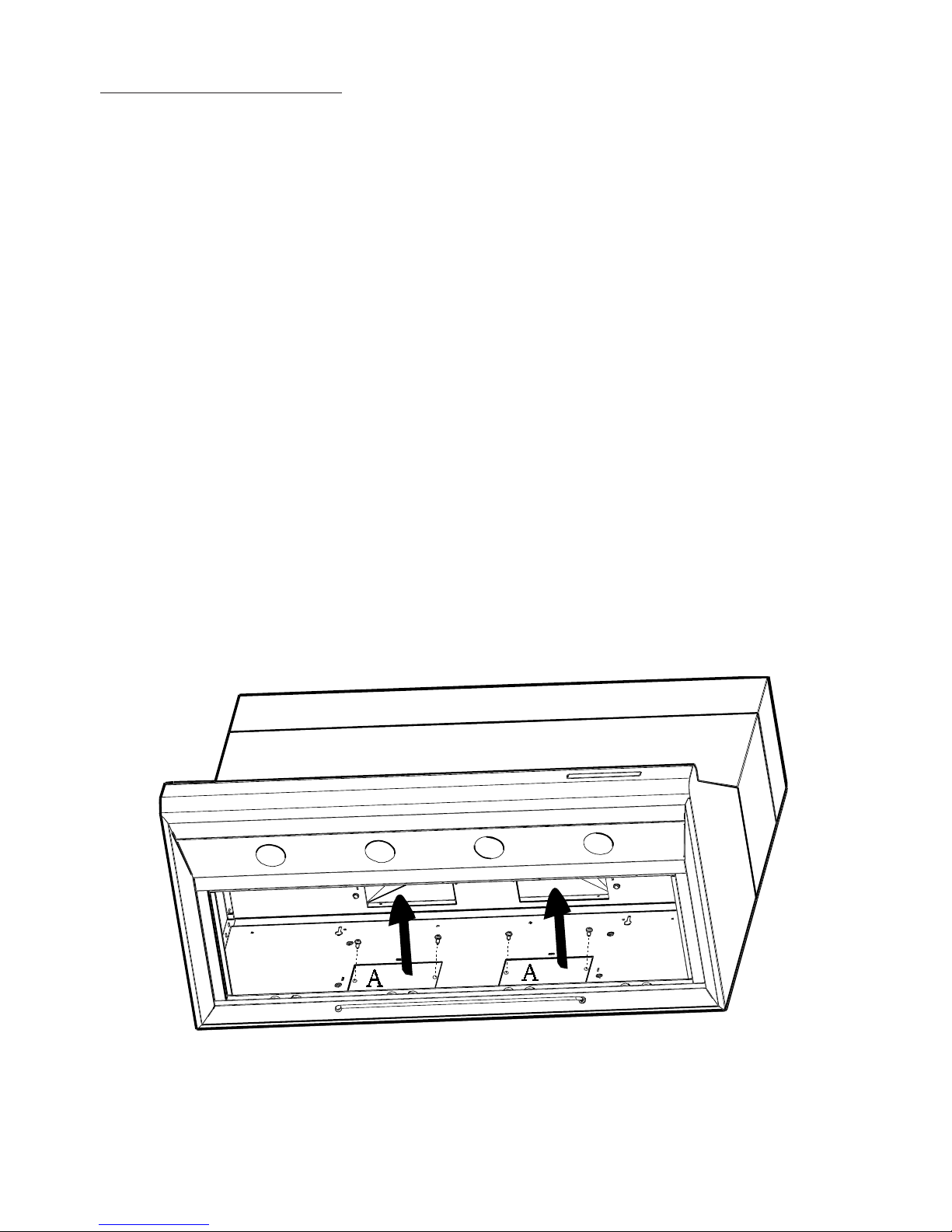
ection: The PHE
hood is shipped ready for vertical
discharge. To change to horizontal discharge simply move the two
plates marked
AA
AA
A in Figure 1 to
the top of the hood. Each plate is
held in place by two sheetmetal
screws.
Assembly of the TAssembly of the T
Assembly of the TAssembly of the T
Assembly of the T
ransition:ransition:
ransition:ransition:
ransition:
The transition supplied with the
PHE hood mounts to the top or
rear of the hood depending on the
discharge direction.
1. Align mounting holes at base
of transition with mounting holes
on 1/2” flange located at the top
or rear of the hood depending on
direction of discharge.
2. Fasten transition to hood
using 6 (4 mm x 9.5 mm) screws
(included with hood).
3. Duct tape connection between
transition and hood.
4. Remove tape holding damper
closed.
Figure 1
Page 5
Page 5
WW
WW
W
all Mount Installationall Mount Installation
all Mount Installationall Mount Installation
all Mount Installation
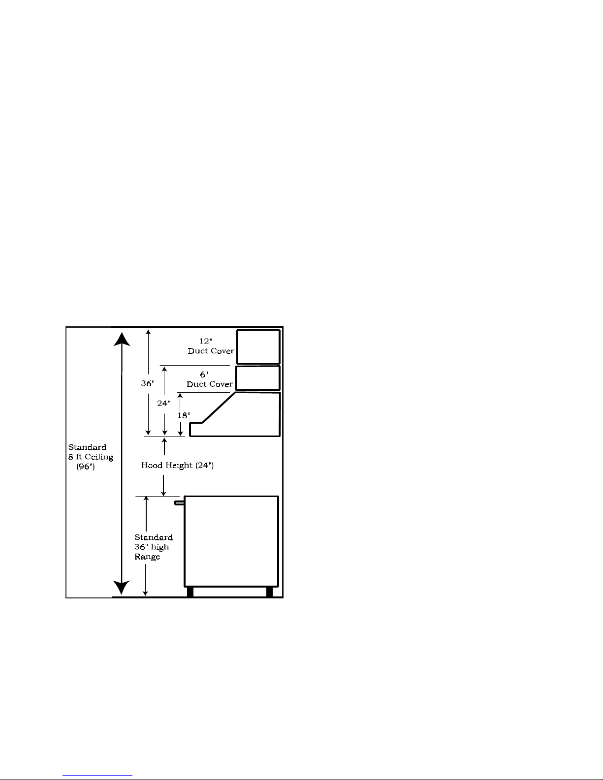
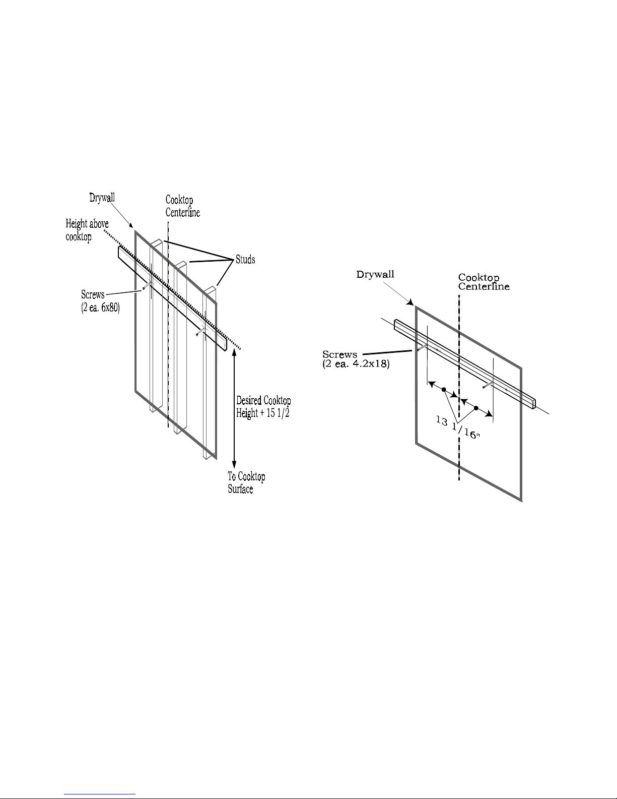
The desired installation
height of the PHE is the
user’s preference. Figure 2
shows a typical installation
of the hood with two duct
covers. Thermador offers 6”
and/or 12” duct covers to
fill the space between the
hood and ceiling.
The installation height
shown in Figure 2 is 24”.
One 6” and one 12” duct
cover have been used in
this installation. Add or
subtract duct
Figure 2
covers as appropriate to
accommodate ceiling height
and desired hood height.
The duct cover structure is
supported by the hood.
1. Hood Installation Height
After the hood installation
height has been determined
draw a horizontal line at a
distance above the cooktop
equal to the desired hood
installation height plus
15.5”. This line is the
mounting location of the
wooden bracket shipped
with the hood.
2. Find the centerline of
the cooktop. Draw a vertical line along this centerline
up to the horizontal line
drawn in step 1.
3. The PHE is mounted to
the wall using a wooden
bracket shipped with the
hood. Remove the bracket
from the hood by removing
two shipping screws. Mark
the centerline of the
bracket.
Page 6
Page 6
4. Find studs behind the
drywall by tapping the wall
or using a stud finder. Locate one stud on either side
of the cooktop centerline to
use for mounting the
wooden bracket as shown in
Figure 3.
Figure 3
5. Align the top of the wood
bracket along the horizontal
line drawn in step 1. Align
the centerlines of the
bracket and cooktop.
6. Drill a 3” deep 1/8” tap
hole through the wooden
bracket, drywall, and into
the stud.
7. Use 2-4 (6mm x 80 mm)
screws to attach the
bracket to the wall as
shown in Figure 3. For
support of longer hoods,
use three or four studs as
available. Countersink the
heads to prevent interference with the hood.
8. On the wood bracket
mark the locations used to
hang the hood according to
Figure 4.
Figure 4
9. Drill a 1/8” tap hole
through the wooden
bracket and drywall. These
screws do not need to go
into the studs.
10. Screw 2 (4.2mm x 18
mm) screws into the wood
bracket leaving 1/4” of the
screw exposed for hanging
the hood.
Page 7
Page 7
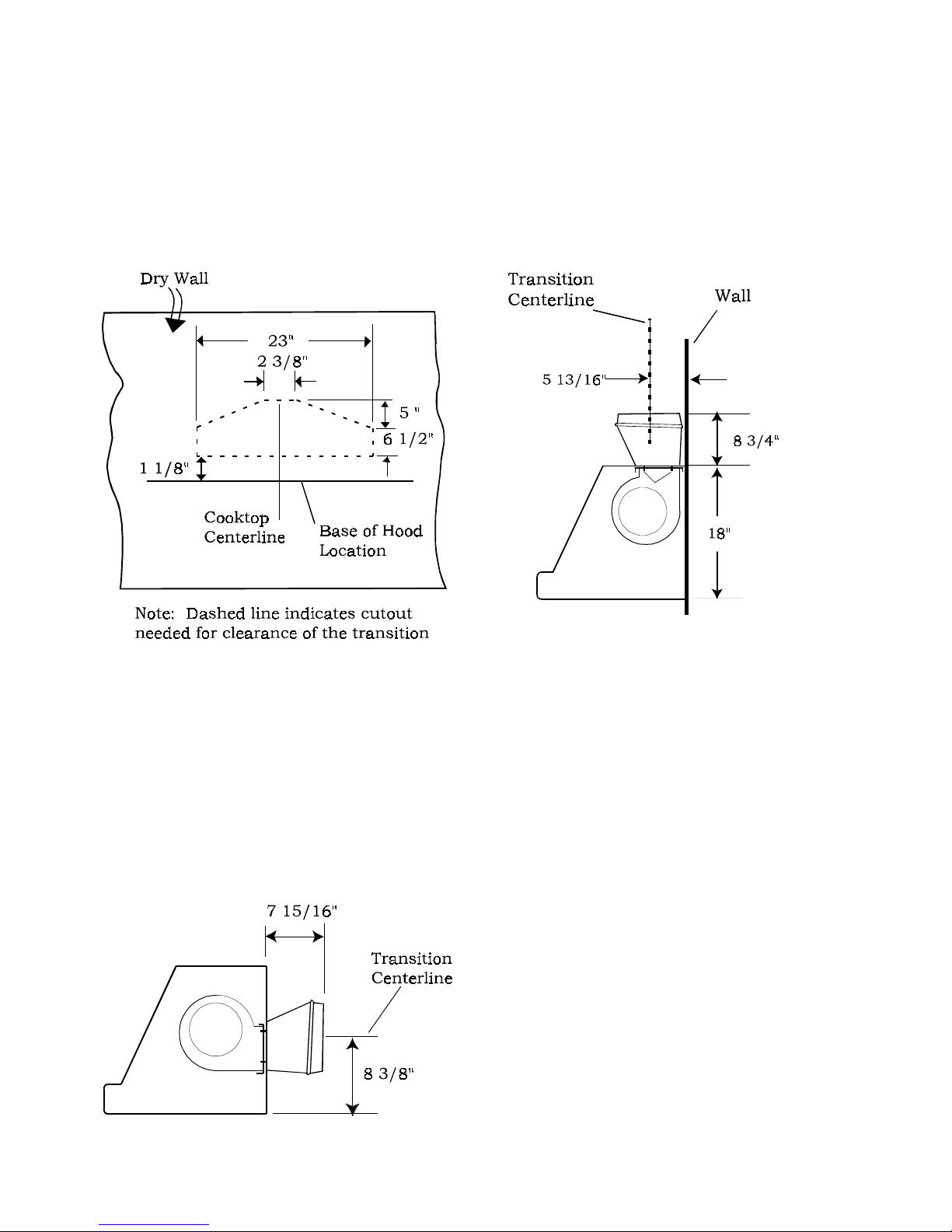
11. Discharge Direction: Horizontal discharge requires a wall
cutout, as shown in Figure 5, to
provide clearance for the transition. The location of the cutout is
determined by the hood installa-
tion height.
Figure 5
The transition supplied with the
PHE connects to standard 10”
round duct. Figure 6 shows the
transition connected for horizontal discharge.
Figure 7 below shows the PHE
configured for vertical discharge.
Installations using this type of
method require a cutout in the
ceiling to accomodate 10” duct
and the 1/2” conduit carrying
power to the unit.
Figure 7
Duct covers, sold separately, are
available to cover the space
between the top of the hood and
ceiling.
Figure 6
Page 8
Page 8
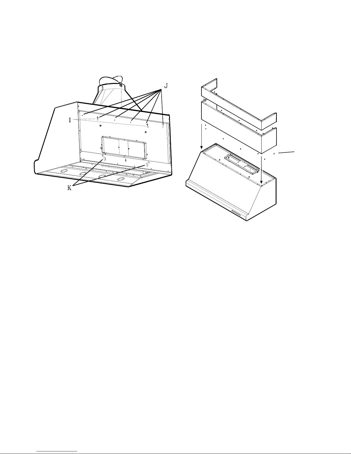
12. Hang the hood using
slots
II
II
I in Figure 8. Make
sure the wood bracket fits
into the recess on the back
of the hood.
Figure 8
13. Tighten the screws in
slots
II
II
I. Use slots
II
II
I to level
the hood.
14. From inside the hood
drive screws (4.2 mm x 18
mm) through holes
JJ
JJ
J into
wooden bracket.
15. Drill a 3/8” tap hole
through the center of the
oval holes K into the wall.
Insert two wall plugs into
drilled holes. Tighten hood
to wall anchors by installing
2 screws with washers.
Assembly and InstallationAssembly and Installation
Assembly and InstallationAssembly and Installation
Assembly and Installation
of the Duct Covers:of the Duct Covers:
of the Duct Covers:of the Duct Covers:
of the Duct Covers:
Optional duct covers shown
in Figure 9 may be used to
fill the space between the
hood and ceiling in wall
mount installations. 6” and
12” high duct covers are
available and may be ordered separately.
1. If multiple duct covers
are used, connect the
pieces together using
sheetmetal screws provided
with chimneys.
Figure 9
2. Attach the duct cover(s)
to the hood using
sheetmetal screws as
shown in Figure 9.
Cabinet Installation:Cabinet Installation:
Cabinet Installation:Cabinet Installation:
Cabinet Installation:
The PHE hood can be installed under a cabinet by
supporting the hood from
the top.
Note: The cabinet mustNote: The cabinet must
Note: The cabinet mustNote: The cabinet must
Note: The cabinet must
be structurally joined tobe structurally joined to
be structurally joined tobe structurally joined to
be structurally joined to
the wall studs to supportthe wall studs to support
the wall studs to supportthe wall studs to support
the wall studs to support
the weight of this hood.the weight of this hood.
the weight of this hood.the weight of this hood.
the weight of this hood.
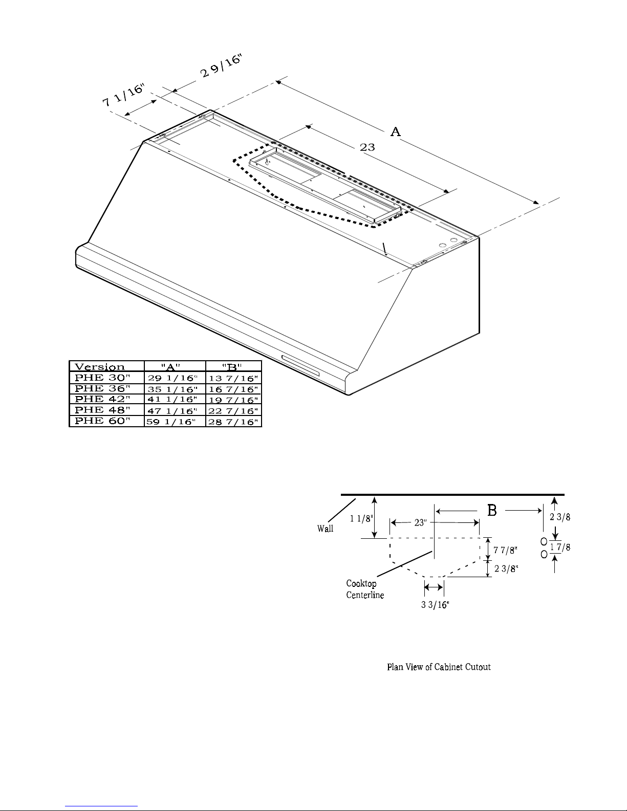
Figure 10 shows the four
holes
used for mounting the
hood to the bottom of the
cabinet.
4x9.5 Screws
(number
depends on
hood size)
Page 9
Page 9
1. In the base of the cabinet drill
1/16” tap holes at the locations
shown in Figure 10. Screw in
four 4.2 mm x 18 mm screws
(provided with hood) leaving 1/4”
exposed.
2. If the hood is installed for
vertical discharge use Figure 11
to create clearance holes for
passage of the transition and
conduit. Dimension A in Figure
11 depends on the hood model
being installed and can be located
in the table above.
Figure 10
Figure 11
""
""""
""
"
""
""""
""
"
Page 10

Page 10
3. For horizontal discharge use
Figure 5 for the geometry of the
cutout required for clearance of
the transition.
4. Hang hood from screws and
tighten securely.
5. Install two wall anchors as
described in step 15 on the
previous page.
Page 11
Page 11
Installing an IntegralInstalling an Integral
Installing an IntegralInstalling an Integral
Installing an Integral
Blower:Blower:
Blower:Blower:
Blower:
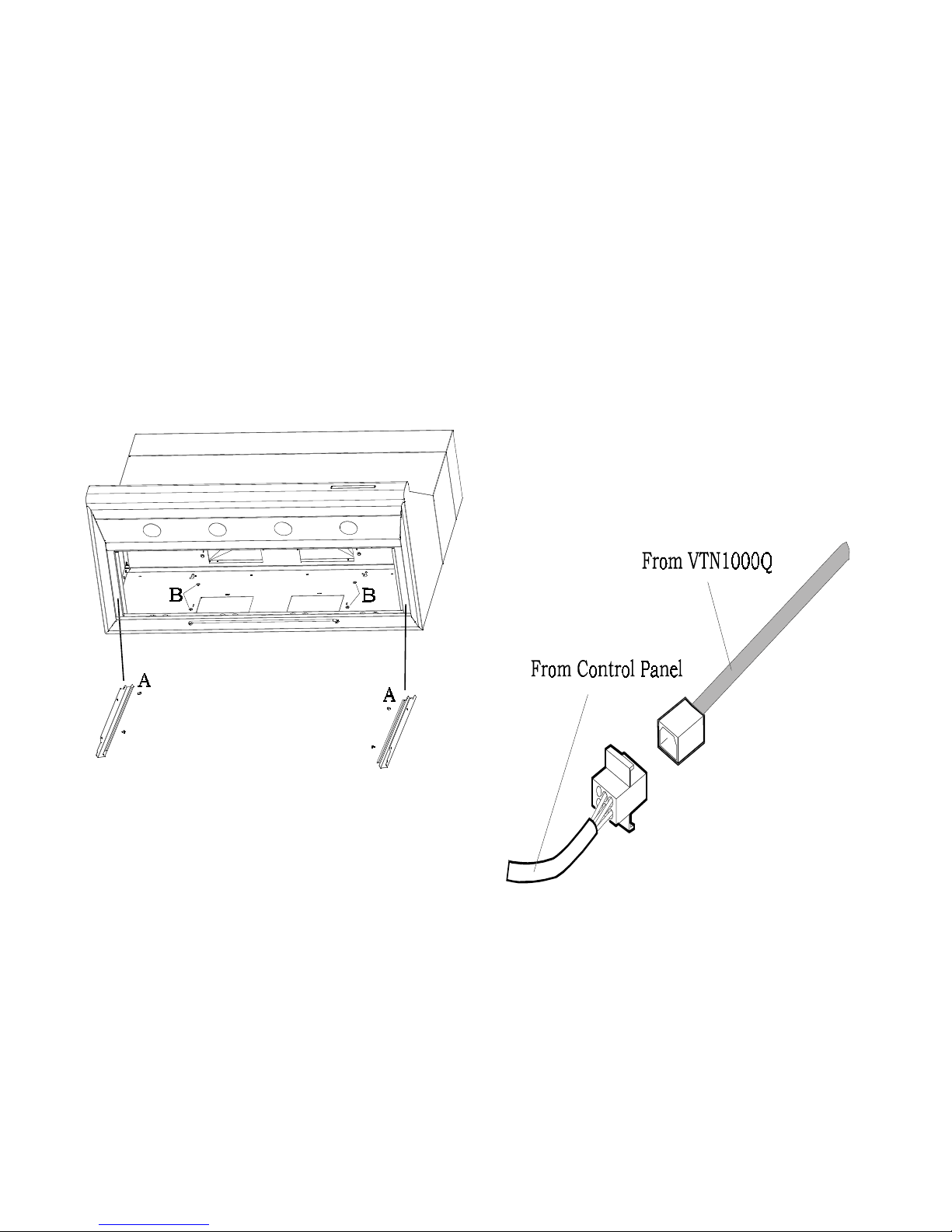
The PHE hood can be installed with Thermador’s
VTN1000Q blower.
1. In the 30” PHE model
remove the two spacers
AA
AA
A
shown in Figure 12. Each
spacer is held in place by
three screws.
Figure 12
2. For horizontal discharge
install four M5 screws in
location
B B
B B
B as shown in
Figure 12. Install the
screws in the hood top plate
for vertical discharge installations. Do not tighten
screws.
3. The four screws in step
two are used to mount the
motor by guiding the screws
into the slots on the motor
mounting plate. Tighten the
screws
BB
BB
B.
WW
WW
W
iring the PHE with aniring the PHE with an
iring the PHE with aniring the PHE with an
iring the PHE with an
Integral motor:Integral motor:
Integral motor:Integral motor:
Integral motor:
WW
WW
W
arar
arar
ar
ning: Turning: Tur
ning: Turning: Tur
ning: Tur
n ofn of
n ofn of
n of
f elec-f elec-
f elec-f elec-
f elec-
tricity at the servicetricity at the service
tricity at the servicetricity at the service
tricity at the service
panel beforpanel befor
panel beforpanel befor
panel befor
e wiring thee wiring the
e wiring thee wiring the
e wiring the
unit.unit.
unit.unit.
unit.
1. Connect the VTN1000Q
molex plug connector to the
connector present inside
the hood as shown in Figure 13.
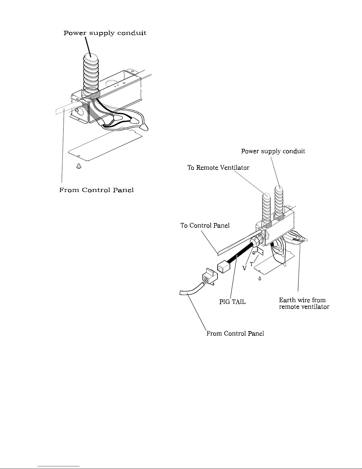
2. Remove the j-box cover
as shown in Figure 14.
3. Remove 1 of 2
knockouts and install 1/2”
conduit connector in j-box.
Figure 13
4. Run black, white, and
green wires (#16 AWG) in
1/2” conduit from power
supply to j-box.
5. Connect black, white,
and green wires from power
supply to black, white, and
green/yellow wires in j-box
respectively.
Page 12
Page 12
Figure 14
6. Close j-box cover. Replace filters as described in
the Care & Use section of
this manual. Turn power on
at service panel. Check
operation of the hood.
Remote BlowerRemote Blower
Remote BlowerRemote Blower
Remote Blower
Installation:Installation:
Installation:Installation:
Installation:
The PHE hood is designed to
work with Thermador’s
VTR600R, VTR1000Q, and
VTR1400Q remote blowers.
For installation instructions
see the instructions supplied
with the blower unit.
WW
WW
W
iring the PHE with airing the PHE with a
iring the PHE with airing the PHE with a
iring the PHE with a
Remote Blower:Remote Blower:
Remote Blower:Remote Blower:
Remote Blower:
WW
WW
W
arar
arar
ar
ning: Turning: Tur
ning: Turning: Tur
ning: Tur
n ofn of
n ofn of
n of
f electric-f electric-
f electric-f electric-
f electric-
ity at the service panelity at the service panel
ity at the service panelity at the service panel
ity at the service panel
beforbefor
beforbefor
befor
e wiring the unit.e wiring the unit.
e wiring the unit.e wiring the unit.
e wiring the unit.
1. Remove the j-box cover
as shown in Figure 15.
2. Remove cover
TT
TT
T from the
j-box.
3. Remove the 2 knockouts
and install 1/2” conduit
connectors.
4. Run black, white, and
green wires (#16 AWG) in
1/2” conduit from power
supply to j-box.
Figure 15
5. Connect black, white,
and green wires from power
supply to black, white, and
green/yellow wires in j-box
respectively.
Page 13

Page 13
6. Connect wire clamp to
“pigtail” as shown in Figure
15. Insert “pigtail” wires
into j-box and fix wire
clamp to j-box using nut
supplied with wire clamp
VV
VV
V.
7. Run five wires (#16
AWG) in 1/2” conduit from
the remote blower to the
second conduit connector.
8. Connect the black,
white, red, and blue wires
from the remote ventilator
to the black, white, red, and
blue wires of the “pigtail
respectively. Connect the
remote blower green/yellow
(ground) wire to the ground
wire from the service panel.
9. Close junction box cover.
Check that all light bulbs
are secure in their sockets.
Install filters. Turn power
on at service panel, and
check lights and blower
operation per Care & Use
section of this manual.
 Loading...