

Page 1
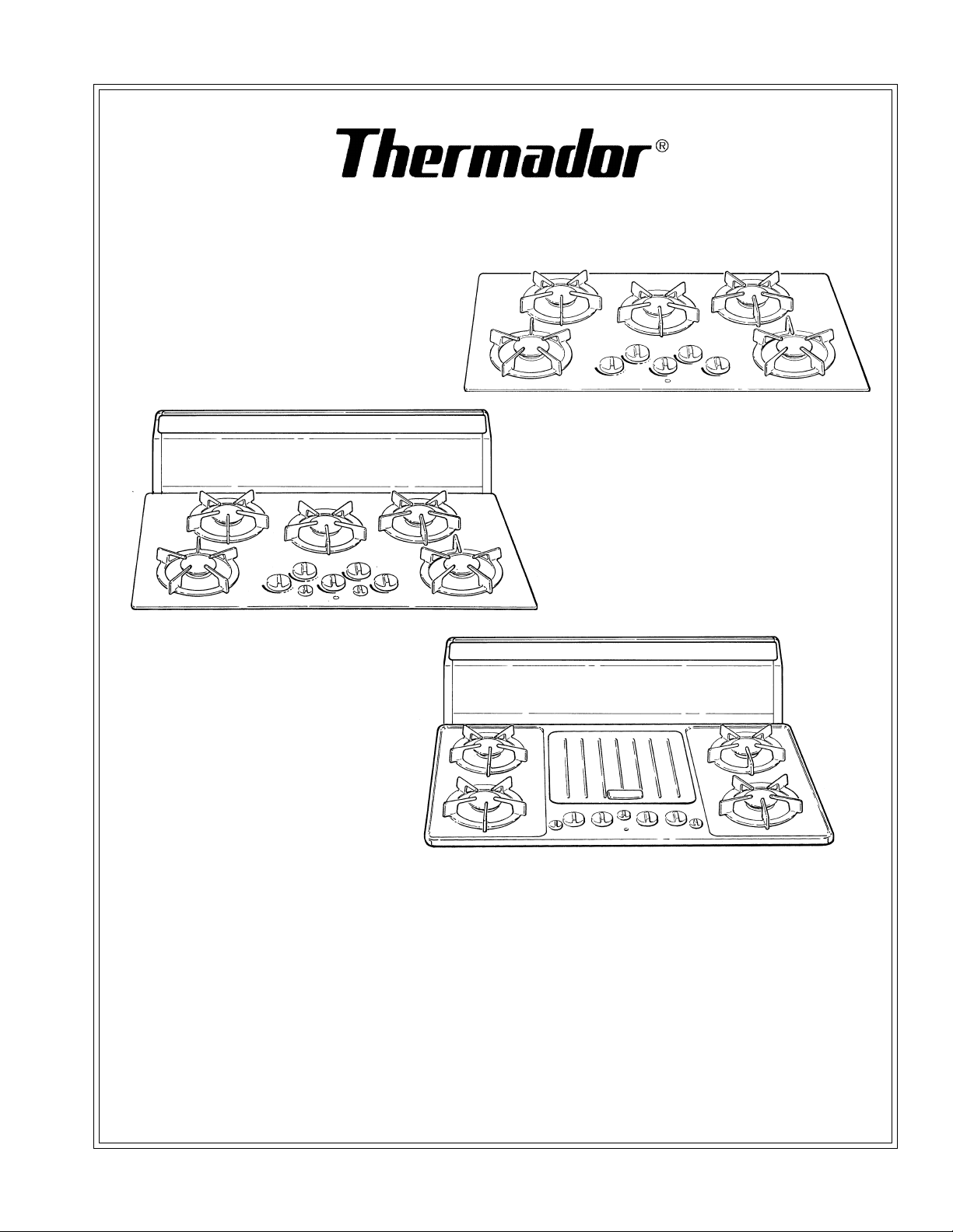
Care and Use Manual
for
ExtraLow
™
Gas Cooktops
Models
GGS30/36/365, GGSCV30/
36/365, SGS30/36G,
SGSCV36G
and
Traditional Series Gas Cooktops
Models
GGN30/36/365, GGNCV30/36/365, SGN30/36G, SGNCV36G
To the Installer: Leave this owner's manual with the cooktop.
To the Consumer: Retain this Care & Use Manual for future reference. Be sure to fill in the information on
Page 28 for warranty validation.
Page 2
A Special Message to Our Customers,
Thank you for selecting a Thermador Gas Cooktop. If you follow the few
simple procedures and suggestions in this manual, the cooktop should give
you years of service.
You have either a steel top or a glass top. The glass cooktop fully meets the
safety and durability requirements of the American Gas Association, the
Canadian Gas Association and the Tempered Glass Association as well as the
stringent test requirements imposed by Thermador. Testing includes dropping a 1.2 pound steel ball from about 2 feet and hitting the glass with a 4 pound
“pan bottom” 10 times. The cooktop is tough, but it is glass. Severe abuse or
excessively rough treatment may break the glass. Tempered glass derives its
excellent strength and heat resistance from powerful internal tensions throughout the piece. When any part of the glass is broken, these tensions are released
throughout the piece. In this unlikely event, the entire glass will break into
many small, blunt pieces called popcorn (the average count is 20 pieces per
square inch). The pieces may scatter somewhat and since most particles are
transparent, food on or near the cooktop should not be eaten. The cooktop
should not be used again until it is repaired by a qualified service technician.
Remember, the steel top is covered with porcelain enamel, which is also a very
durable glass. Severe abuse or excessively rough treatment may cause the
porcelain enamel to chip.
There is no limit to the types of food which can be cooked on your cooktop, but
some utensils could harm it. Do not use any utensil which spans two burners
because this will excessively heat the space between them. Utensils which
have large overhangs beyond the burner grate may cause over heating or
tipping, if used for long periods of time. Of course, hard impact should be
avoided.
We recommend that you read this entire manual before using your new
cooktop. We know you will enjoy cooking on your new cooktop. Please
contact us if you have questions or comments. When you write, please include
the model and serial numbers of your cooktop.
Sincerely,
The Home Economics Staff
Page 3
TABLE OF CONTENTS
Propane Installation ................................... 2
Section One:
General Safety Instructions................. 3 to 6
Safety/Electrical Requirements ................ 3
Precautions .............................................. 4
Section Two: Before you Begin ................... 6
Before using your Cooktop ....................... 6
Section Three: Description ................ 7 to 10
Models GGS30, GGN30, GGSCV30
GGNCV30................................................. 7
Models GGSCV36, GGSCV365,GGNCV36,
GGNCV365............................................... 8
Models GGS36, GGN36, GGS365,
GGN365 ................................................... 9
Models SGS30, SGN30, SGS36G,
SGN36G, SGSCV36G,SGNCV36G........... 10
Section Four: Using the Cooktop ..... 10 to 21
Cooktop Operation ................................. 11
Proper Cookware .................................... 14
Flame Setting Chart ............................... 16
Griddle'N Grill Operation ........................ 19
Cook'n'Vent Operation............................ 21
Section Five: General Care .............. 22 to 27
General Care .......................................... 22
Cleaning Chart ....................................... 23
Cook'n'Vent Care .................................... 26
Section Six: Service ....................... 28 to 29
Before Calling For Service....................... 28
Warranty ................................................ 29
WARNING
If the information in this manual is not followed exactly, a fire or explosion
may result causing property damage, personal injury or death.
— Do not store or use gasoline or other flammable vapors and liquids in the
vicinity of this or any other appliance.
WHAT TO DO IF YOU SMELL GAS
• Do not try to light any appliance.
• Do not touch any electrical switch; do not use any phone in your building.
• Immediately call your gas supplier from a neighbor’s phone. Follow the gas
supplier’s instructions.
• If you cannot reach your gas supplier, call the fire department.
— Installation and service must be performed by a qualified installer, service
agency or the gas supplier.
Page 1
Page 4
PROPANE INSTALLATION
PROPANE GAS INSTALLATION
The cooktop is ready for use with natural gas. It
may be converted for use with propane gas
using the Burner Propane Conversion Kit, Model
NLPKIT6, Part Number 35-00-688. A qualified
service techhnican or installer can convert the
cooktop. Be sure the unit being installed is
correct for the type of gas being used. Refer to
the Rating plate on the right side underneath
the cooktop, see pages 7 to 10 for the location.
CAUTION
When connecting the unit to propane gas, make
certain the propane tank is equipped with its
own high pressure regulator. In addition the
pressure regulator supplied with the cooktop
must be on the inlet gas pipe of this unit. The
maximum gas pressure to this appliance is
not to exceed 14.0 inches water column from
the propane gas tank pressure regulator.
TESTED IN ACCORDANCE WITH ANSI
Z21.1, STANDARD FOR HOUSEHOLD
COOKING GAS APPLIANCES, and CAN/
CGA 1.1 DOMESTIC GAS RANGES.
Check your local building codes for the
proper method of installation. In the absence of local codes this unit should be
installed in accordance with the National
Fuel Gas Code No. Z223.1 Current Issue
and National Electrical Code ANSI/NFPA
No. 70 Current Issue or the CAN - B149
Installation Codes for Gas Burning Appliances and C22.1 Canadian Electrical Code
Part 1.
Page 2
Page 5
Section One: General Safety Instructions
ELECTRICAL REQUIREMENTS AND GROUNDING INSTRUCTIONS
PLEASE READ CAREFULLY
See Installation Instructions for electrical requirements and
MODELS: GGS30/36/365,
GGSCV30/36/365,
SGS30, GGN30/36/365
GGNCV30/36/365 &
SGN30
Rated 120 volt, 60 Hz., 1.0 Amp.
.
MODELS: SGS36G, SGSCV36G
SGN36G & SGNCV36G
Rated 120 volt, 60 Hz., 11.7 Amp
grounding instructions.
DO NOT UNDER ANY CIRCUMSTANCES CUT OR REMOVE THE
THIRD (GROUND) PRONG FROM THE POWER CORD PLUG.
If the electrical outlet you intend to use does not accept the 3-prong
plug, it is the personal responsibility and obligation of you, the user, to
have it replaced with a properly grounded 3-prong wall receptacle in
accordance with the National Electrical Code and/or applicable local
codes and ordinances, by a qualified electrician.
SAFETY
FOR PERSONAL SAFETY,
THIS APPLIANCE MUST BE
PROPERLY GROUNDED.
ALWAYS DISCONNECT THE
ELECTRICAL PLUG FROM THE
WALL RECEPTACLE BEFORE
SERVICING THIS UNIT.
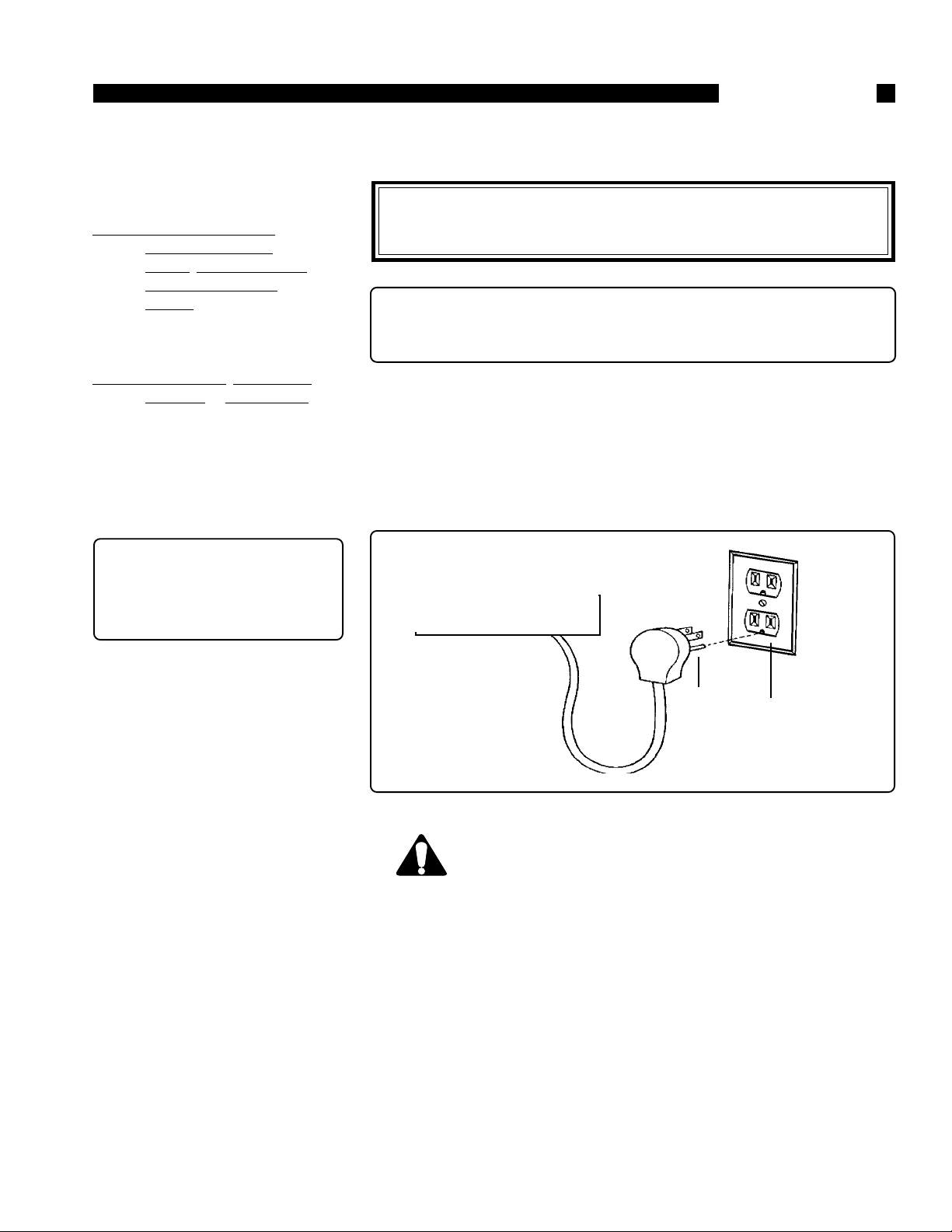
The power cord on your cooktop
is equipped with a three prong
grounding plug with polarized
parallel blades. This type of plug
is for your protection against
shock hazard. This cord must be
plugged directly into a properly
grounded 3-prong wall receptacle
that is connected to a correctly
polarized 120 volt electric power
supply. It is recommended that a
separate circuit serving each appliance be provided.
Cooktop
Cook'n'Vent (optional)
➛
➛
Three
Prong
Plug
CAUTION - ALL MODELS
Outlet
IN CASE OF AN ELECTRICAL FAILURE
If for any reason a gas control knob is turned ON and there is no electric
power to operate the electronic igniter of the cooktop, turn OFF the gas
control knob and wait 5 minutes for the gas to dissipate before lighting
the burner manually. On the models with the ExtraLow™ Gas the two
left burners cannot be turned on manually.
To light the burners, carefully hold a lighted match to the burner ports
and turn the gas control knob to HI. During a power failure you can use
the cooktop burners, but each must be lit with a match.
Page 3
Page 6

PRECAUTIONS
SAFETY PRACTICES TO AVOID
Section One: General Safety Instructions
PERSONAL INJURY
IMPORTANT SAFETY INSTRUCTIONS
WARNING - TO REDUCE THE
RISK OF FIRE, ELECTRIC
SHOCK, OR INJURY TO PERSONS, OBSERVE THE FOLLOWING:
A. Use this unit only in the man-
ner intended by the manufacturer. If you have any questions, contact the manufacturer.
B. Before servicing or cleaning
unit, switch power off at service panel and lock service
panel to prevent power from
being switched on accidentally.
CAUTION: For General Ventilating
Use Only. Do Not Use To Exhaust
Hazardous or Explosive Materials
and Vapors.
WARNING - TO REDUCE THE
RISK OF FIRE, ELECTRIC
SHOCK, OR INJURY TO PERSONS, OBSERVE THE FOLLOWING:
A. Keep fan, filters and grease
laden surfaces clean.
B. Always turn hood ON when
cooking at high heat.
C. Use high range settings on
range only when necessary.
Heat oil slowly on low to medium setting.
D. Do not leave range unattended
when cooking.
E. Always use cookware and uten-
sils appropriate for the type
and amount of food being prepared.
WARNING - TO REDUCE THE
RISK OF INJURY TO PERSONS,
IN THE EVENT OF A RANGE TOP
GREASE FIRE, OBSERVE THE
FOLLOWING:
A. SMOTHER FLAMES with a
close-fitting lid, cookie sheet.
or other metal tray, then turn
off the gas burner or the elec-
tric element. BE CAREFUL TO
PREVENT BURNS. If the flames
do not go out immediately
EVACUATE AND CALL THE
FIRE DEPARTMENT.
B. NEVER PICK UP A FLAMING
PAN - You may be burned.
C. DO NOT USE WATER, includ-
ing wet dishcloths or towels - a
violent steam explosion will
result.
D. Use an extinguisher ONLY if:
1. You know you have a Class
ABC extinguisher, and you
already know how to operate it.
2. The fire is small and contained in the area where it
started.
3. The fire department is being called.
4. You can fight fire with your
back to an exit.
When properly used and cared
for your new Thermador Cooktop has been designed to be a safe,
reliable appliance. When using
kitchen appliances, basic safety
precautions must be followed, including the following:
Read this Care and Use Manual
carefully before using you new
cooktop to reduce the risk of fire,
electric shock, or injury to persons.
Begin by insuring proper installation and servicing. Fol-
low the installation instructions provided with this product. Have the cooktop installed
and grounded by a qualified
technician. Have the installer
show you where the gas shutoff valve is located so that you
know how and where to turn
off the gas to the cooktop.
Page 4
If you smell gas, your installer
has not done a proper job of
checking for leaks. Connections can loosen in transit. If
the connections are not perfectly tight, you can have a
small leak and therefore a faint
gas smell. Finding a gas leak is
not a “do-it-yourself” procedure. Some leaks can only be
found with the burner control
in the ON position.
Page 7

Section One: General Safety Instructions
PRECAUTIONS
For proper lighting and performance of the burners, keep the ig-
niters clean. It is necessary to clean
these when there is a boil over, or
when the burner does not light
even though the electronic igniters click. See page 22.
The cooktop is factory
assembled for natural gas. It
should be correctly adjusted by a
qualified service person or installer for the type of gas with
which it is used. (See page 2 for
propane gas.)
Do not repair or replace any part
of the appliance unless specifi-
cally recommended in this
manual. All other servicing
should be referred to a qualified
technician.
Children should not be left alone
or unattended in an area where
appliances are in use. They
should never be allowed to sit or
stand on any part of the appliance.
CAUTION: Do not store items
of interest to children above the
cooktop or at the back. If chil-
dren should climb onto the appliance to reach these items, they
could be seriously injured.
Do not store flammable materials on or near the cooktop.
Do not use water on grease fires.
Turn appliance off and smother
fire with baking soda or use a dry
chemical or foam-type extinguisher.
Never let clothing, potholders,
or other flammable materials
come in contact with the burners
or burner grates, until they are
cool to the touch.
Use only dry potholders; moist
or damp potholders on hot surfaces may cause burns from steam.
Do not use a towel or other bulky
cloth in place of potholders. Do
not let potholders touch hot burners or burner grates.
For personal safety, wear proper
apparel. Loose fitting garments
or hanging sleeves should never
be worn while cooking.
Do not use aluminum foil to line
any part of the cooktop. Improper
use of a foil liner could result in a
shock, fire hazard or it could obstruct the flow of combustion and
ventilation air. Foil is an excellent
heat insulator and heat will be
trapped beneath it. This will upset the cooking performance and
can damage the cooktop finish.
Warning: The appliance is for
cooking. Based on safety consid-
erations never use the cooktop to
warm or heat a room. Also, such
use can be damaging to the
cooktop.
Do not heat unopened food containers; a buildup of pressure may
cause the container to burst.
When using the cooktop: DO
NOT TOUCH THE BURNER
GRATES or THE IMMEDIATE
SURROUNDING AREA. Areas
adjacent to the burners may become hot enough to cause burns.
Never leave the burners unattended when using high flame
settings. Boil overs cause smoking, and greasy spillovers that may
ignite. More importantly, if the
flame is smothered, unburned gas
will be coming into the room. See
“What to do if you smell Gas”,
Page 1.
Always use utensils that have
flat bottoms. Hold the handle of
the pan to prevent movement of
the utensil when stirring or turning food.
To minimize burns, ignition of
flammable materials and unintentional spillovers, position handles
of utensils inward so they do not
extend over adjacent work areas,
burners, or the edge of the
cooktop.
During cooking, set the burner
control so that the flame heats
only the bottom of the pan and
does not extend beyond the edge
of the pan.
Take care that drafts like those
from fans or forced air vents do
not blow flammable material toward the flames or push the flames
so that they extend beyond the
edges of a pot.
Only certain types of glass, heatproof glass-ceramic, ceramic,
earthenware, or other glazed
utensils are suitable for cooktop
use. This type of utensil may break
with sudden temperature
changes. Use only on low or medium flame settings according to
the manufacturer’s directions.
If the cooktop is near a window,
be certain the curtains do not
blow over or near the burners;
they could catch on fire.
In the event a burner goes out and
gas escapes, open a window or a
door. Do not attempt to use the
cooktop until the gas has had time
to dissipate. Wait at least 5 min-
utes before using the cooktop.
Page 5
Page 8

PRECAUTIONS
Section One: General Safety Instructions
Clean the cooktop with caution.
Avoid steam burns; do not use a
wet sponge or cloth to clean the
cooktop while it is hot. Some
cleaners produce noxious fumes
if applied to a hot surface.
Clean the hood above or the ventilator at the back of your cooktop
frequently so grease from cook-
ing vapors does not accumulate
on the filters or on the intake.
SAVE THESE INSTRUCTIONS
BEFORE USING YOUR COOKTOP FOR THE FIRST TIME
Turn the ventilator OFF in case
of fire or when intentionally
“flaming” liquor or other spirits
on the cooktop. The blower, if in
operation, could unsafely spread
the flames.
The electric element is
removeable, however it should
never be immersed in water. Turn
the element on and it will clean
itself. DO NOT leave it unattended
when burning off food soil.
California Proposition 65 - Warn-
ing: Burning gas cooking fuel generates some by-products which
are on the list of substances which
are known by the State of California to cause cancer or reproductive harm. California law requires
businesses to warn customers of
potential exposure to such substances. To minimize exposure to
these substances, always operate
this unit according to the instructions contained in this booklet and
provide good ventilation.
Section Two: Before You Begin
Remove all packaging
materials and labels before
using your cooktop.
1. Check that you havethese items.
GGS30/36, GGSCV30/36
GGN30/36, GGNCV30/36
/
▲ 4 Burner Grates
▲ 4 Burner Caps
▲ 2 Ventilator Filters*
▲ Care and Use Manual
(warranty found on Page 29).
GGS365, GGSCV365
GGN365, GGNCV365
▲ 5 Burner Grates
▲ 5 Burner Caps
▲ 2 Ventilator Filters*
▲ Care and Use Manual (war-
ranty found on Page 29).
SGS30, SGS36G, SGSCV36G
▲ 4 Burner Grates
▲ 4 Burner Caps
▲ Griddle'n Grill™ (drip pan,
cover, griddle, grill, removable element)**
▲ 2 Ventilator Filters*
▲ Care and Use Manual
(warranty found on Page 29).
SGN30, SGN36G, SGNCV36G
▲ 4 Burner Grates
▲ 4 Burner Caps
▲ Griddle (drip pan, cover,
griddle, removable element)**
▲ 2 Ventilator Filters*
▲ Care and Use Manual
(warranty found on Page 29).
2. Record the Model and Serial
Number as described on page
28. These may be used for any
future contacts with your servicer
or the factory.
* Cook'n'Vent models only.
** Griddle'n Grill or griddle models
only.
Page 6
Page 9
Section Three: Description
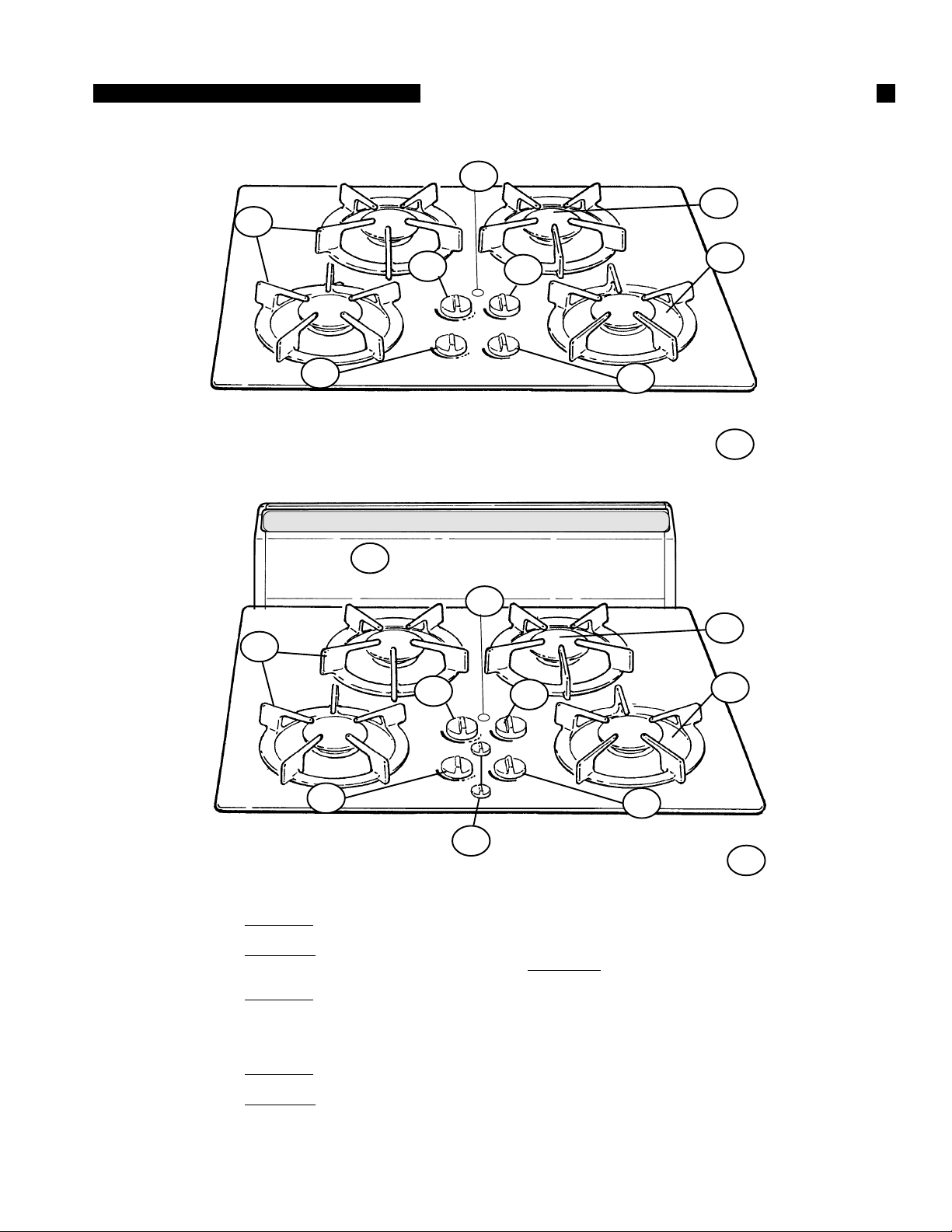
Models GGS30* & GGN30
10
MODEL AND PARTS IDENTIFICATION
7
9
2
Model GGSCV30* & GGNCV30
1
10
3
4
8
5
➚
11
7
9
3
4
8
2
1. Cook'n'Vent™
2. Models GGS - ExtraLow™ 300 to 9,100
BTU/HR Burner & Control Knob
Models GGN - 950 to 6,500 BTU/HR
Burner & Control Knob
3. Models GGS - ExtraLow™ 365 to 11,000
BTU/HR Burner & Control Knob
GGN Models - 1650 to 11,000 BTU/HR
Burner & Control Knob
4. Models GGS - 1300 to 9100 BTU/HR
Burner & Control Knob
Models GGN - 950 to 6500 BTU/HR
Burner & Contol Knob
5
6
5. 1650 to 11,000 BTU/HR Burner
& Control Knob
6. Ventilator Controls
7. Models GGS - "ON" Light
8 . Burner Plate
9 . Burner Cap
1 0 . Grates
1 1. Rating Plate, Right Side, under-
neath Cooktop
Page 7
➚
11
* GGS models
illustrated
Page 10
MODEL AND PARTS IDENTIFICATION
Model GGSCV36* & GGNCV36
1
11
Section Three: Description
10
3
2
8
7
7
Model GGSCV365* & GGNCV365
1
11
5
9
6
➚
12
10
3
2
7
Page 8
4
8
7
5
9
6
➚
12
*GGSCV models illustrated
Page 11

Section Three: Description
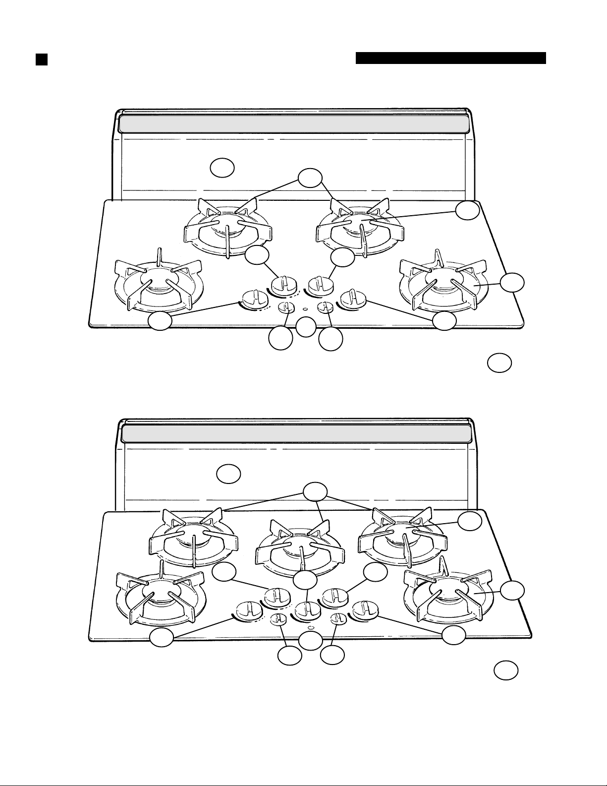
Models GGS36* & GGN36
MODEL AND PARTS IDENTIFICATION
3
2
Models GGS365* & GGN365
11
3
11
10
5
9
8
6
➚
12
10
4
5
2
1. Cook'n'Vent
2. Models GGS - ExtraLow™ 300 to 9100
BTU/HR Burner & Control Knob
Models GGN - 950 to 6,500 BTU/HR
Burner & Control Knob
3. Models GGS - ExtraLow™ 365 to
11,000 BTU/HR Burner & Control
Knob
Models GGN - 1650 to 11,000 BTU/
HR Burner & Control Knob
4. Models GGSCV365, GGS365 &
GGN365 - 950 to 6,500 BTU/HR
Burner & Control Knob
9
6
8
➚
12
5. Models GGS - 1300 to 9,100
BTU/HR Burner & Control Knob
Models GGN 950 to 6,500 BTU/
HR Burner & Control Knob
6 . 1650 to 11,000 BTU/HR Burner &
Control Knob
7 . Ventilator Controls
8. Models GGS - "ON" Light
9 . Burner Plate
10. Burner Cap
1 1 . Grate
1 2. Rating Plate, Right Side, Underneath
Cooktop
*GGS models
illustrated
Page 9
Page 12

MODEL AND PARTS IDENTIFICATION
Section Three: Description
Models SGS30* & SGN30
Models SGS36G* & SGN36G
Model SGSCV36G* &
SGNCV36G
10
9
3
4
8
2
7
5
➚
11
10
9
3
12
4
8
2
7
13
5
➚
11
1
10
1. Cook'n'Vent
2. Models SGS - ExtraLow™ 300 to 9100
BTU/HR Burner & Control Knob
Models SGN - 950 to 6,500 BTU/HR
Burner & Control Knob
3. Models SGS - ExtraLow™ 365 to
11,000 BTU/HR Burner & Control
Knob
Models SGN - 1650 to 11,000 BTU/HR
Burner & Control Lnob
4. Models SGS - 1300 to 9,100 BTU/HR
3
2
6
Burner & Control Knob
Models SGN - 950 to 6,500 BTU/
HR Burner & Control Knob
5 . 1650 to 11,000 BTU/HR Burner &
Control Knob
6 . Ventilator Controls
7 . "ON" Light except SGN30
8 . Burner Plate
9 . Burner Cap
12
13
7
1 0 . Grates
1 1. Rating Plate, Right Side, Underneath
Cooktop
12. Models SGS - Griddle'n Grill
13. Models SGSG - Griddle'n Grill
Control Knob
Models SGNG - Griddle only Control
Knob
*SGS models illustrated
4
5
9
8
➚
11
Page 10
Page 13

Section Four: Using the Cooktop
COOKTOP OPERATION
CONTROL KNOB — ALL STANDARD BURNERS
Glass
Models
HI
OFF
LO
STANDARD BURNER CONTROL KNOB SETTINGS
Porcelain/Stainless
Models
THERMADOR
®
EXTRALOW™ BURNERS
(ModelsGGS/SGS)
The left front 9,100 BTU/HR burner
and left rear 11,000 BTU/HR burner
are designed to provide flame settings which enable you to simmer,
poach, melt and hold cooked food at
a serving temperature, without
scorching or burning. This is accomplished by cycling the flame OFF and
ON for varying lengths of time.
All the controls are push in to turn and have an infinite number of heat settings,
with no fixed positions. Select the appropriate control knob and turn it
counterclockwise to the HI position (detent) until the burner lights. Adjust the
flame size. Turn off by turning the control clockwise to OFF.
CONTROL KNOB —
Thermador® ExtraLow™ BURNERS
GGS
Glass
Models
HI
OFF
XLO
LO
ExtraLow™ CONTROL KNOB SETTINGS
Both ExtraLow controls are push in to turn and have an infinite number of heat
settings, with no fixed positions. The ExtraLow settings are between XLO and
just after LO, at the detent, shown by the broken line.
2
1
1. ExtraLow™ 300 to 9,100 BTU/
HR Burner and Control Knob
2. ExtraLow™ 365 to 11,000
BTU/HR Burner and Control
Knob
3. 950 to 6,500 BTU/HR Burner
and Control Knob (Models
1
1
SGS
Porcelain/
Stainless Models
3
4
3
2
4
5
GGSCV365 and GGS365)
4. 1300 to 9,100 BTU/HR Burner
and Control Knob
5. 1650 to 11,000 BTU/HR Burner
and Control Knob
Model GGS365
5
HOW THEY WORK
• The BTU/HR usage on the 9,100
BTU/HR burner ranges from HI
(at 9,000) to XLO (at 300). The
BTU/HR usage on the 11,000
BTU/HR burner ranges from HI
(at 11,000) to XLO (at 365).
• There are an infinite number of
settings between HI and XLO; the
control knob can be set at any position.
• The burner flame will pulse ON
and OFF when the setting is at any
position between LO and XLO.
• The length of time the flame is ON
and OFF varies.
• With a setting just below LO, the
flame will be ON approximately
50 seconds and OFF 10 seconds of
each minute.
• With a setting at the XLO position,
the flame is ON approximately 10
seconds and OFF 50 seconds of
each minute.
FOR THE BEST RESULTS
• Temperature control will be more
accurate if a lid is used.
• Bring food to a rolling boil; stir
well to be sure all the food is boiling; cover and reduce the heat to
just below LO.
• Check periodically to see if the
control knob should be turned to a
lower setting.
Page 11
Page 14

COOKTOP OPERATION
Section Four: Using the Cooktop
• Adjust control knob to lower settings in small steps.
• If control is set too low to maintain simmer, bring the food back
to a boil before setting a higher
simmer setting.
WHAT TO EXPECT
• The type and quantity of the food
will affect which setting to use.
• The size, type and material of your
pan will affect which setting to
use.
• When a large pan is used on a
small burner, it may cause the
simmer action to occur mainly in
the center of the pan. When the
food is stirred, the cooler food
near the edges of the pan may
result in an overall temperature
too cool to simmer. If this happens, turn the burner up slightly.
• It is normal to stir food occasionally. This is especially important
when simmering for several
hours. For example: a homemade
spaghetti sauce or beans.
• It is normal not to see simmer
bubbles immediately after the
food has been stirred.
SEALED BURNERS
Front of Burner
SEALED BURNER
Your new cooktop features four or
five sealed gas burners. On Models GGS30/36/365, GGSCV30/
36/365, SGS30/30G and
SGSCV36G you have two 9,100
BTU/HR burners, two 11,000
BTU/HR burners and on the
GGSCV365 or GGS365 there is
one 6,500 BTU/HR burner. On
Models GGN30/36/365 and
SGN30/36 there are two 11,000
BTU/HR and two or three 6,500
BTU/HR burners. Each burner is
sealed to the cooktop for easier
cleaning.
BURNER CAPS
BURNER PLATES
Burner Base (C)
Indentation (E)
Notch (B)
Igniter (D)
BURNER PLATE
The Burner Plate has a notch (B) on
the burner base, directly across
from the igniter (D). This is where
the tab (A) on the burner cap fits.
❐ NOTE: For proper burner op-
eration be sure the tab (A) on the
underside of the burner cap fits
into the corresponding notch (B)
on the burner plate.
GRATES
• While the flame is ON there may
be bubbling; there should be at
least steam and a slight quivering
of the liquid’s surface.
• Simmer bubbles may not be seen
when the flame has cycled OFF.
(Models GGS & SGS)
SIGNAL LIGHT
The Signal Light (not on all models),
or "ON" Light is located in the area of
the Control Knobs. For location see
"Section Three: Description", located
on pages 7 to 9, to identify your model.
This light turns on when any Control
Knob is set.
Tab (A)
BURNER CAP
The Burner Cap top is porcelain
enamel and has a tab (A) on the underside that fits into the notch (B) on
the burner base (C).
BE SURE ALL BURNERS
ARE IN THE OFF POSI-
TION BEFORE WIPING
OR CLEANING THE
COOKTOP.
Page 12
Extension
(E)
GRATE (Underside)
The five finger grates are porcelain
enameled cast iron or steel and have
an extension (E) that is longer (underneath) than the other four. This
extension fits into the indentation (E)
on the burner plate, which is directly
across from the igniter (D).
Page 15

Section Four: Using the Cooktop
COOKTOP OPERATION
ELECTRONIC IGNITION
IGNITER
The cooktop uses electronic igniters to light the burners. Each
burner has its own igniter that
sparks when any burner is turned
on. When the igniters are clicking
(sparking), do not touch the burners. If a burner fails to ignite, see
“Before Calling For Service,” Page
28.
AUTOMATIC RE-IGNITION
If
any burner flame blows out, the
electronic igniter automatically
sparks on all burners to relight
the flame. Do not touch any burner
while the igniters are clicking.
POWER FAILURE
In the event of a power failure, only
the standard burners can be lighted
manually (the burners on the left on
Models GGS & SGS cannot be lit). It
is necessary to light each standard
series burner individually.
If the cooktop is being used when the
power failure occurs, turn all the
burner control knobs to the OFF position. Then, the standard burners
can be lighted by holding a match at
the ports and turning the control knob
to the HI position. Wait until the
flame is burning all the way around
the burner cap before adjusting the
flame to the desired height.
The two ExtraLow™ (Models GGS &
SGS) burners, on the left side, cannot
be used during a power failure. Be
sure to turn them OFF if a power
failure occurs, as they will not turn
back on until both control knobs are
turned OFF and then turned back on
again. See “What To Do If You Smell
Gas,” Page 1.
FLAME HEIGHT
The correct height of the flame depends on the size and material of the
utensil being used, the food being
cooked and how much liquid is in the
utensil. Here are some basic rules for
selecting the flame height.
s The flame should never extend
beyond the bottom of the pan.
s Utensils which conduct heat
slowly (such as glass-ceramic)
should be used with a low or
medium flame unless you are
cooking with a large amount of
liquid.
BURNER EFFICIENCY
and FLAME
CHARACTERISTICS
The burner flame should be blue in
color and stable with no yellow tips,
excessive noise or fluttering. It should
burn completely around the burner
cap.
Foreign particles in the gas line may
cause an orange flame during initial
use. This should disappear with use.
If the flame does not burn evenly all
the way around the burner cap, be
sure the cap is resting correctly on the
burner base.
If the ports are clogged, use a wire, a
straightened paper clip or a needle to
clear the ports. Do not use a tooth-
pick; it could break off inside the
port. If the condition persists, contact
a service agency for adjustment.
The burner should light in 4 seconds or less. If a burner does not
light, check to see that the cap is
resting correctly on the burner base.
FOR PROPER COMBUSTION
DO NOT USE THE COOKTO
WITHOUT THE BURNER GRATES IN PLACE.
CAUTION
▲ Foods packaged in aluminum
foil should not be placed di-
rectly on the burner grate for
cooking: aluminum foil can
melt.
▲ Plastic, paper and cloth can
melt or burn when in contact
with a hot burner grate. Do
not let these items come in contact with the burner grate.
▲ Do not allow pans to boil dry.
This can damage the pan, the
burner grate, the cooktop glass
and/or the burner plate.
Ports
BURNER CAP
Page 13
Page 16

Section Four: Using the Cooktop
PROPER COOKWARE
Top performance of your new cooktop is directly related to the use of proper pots and pans. An out-ofshape pan, without a lid, cannot possibly cook with the same speed and evenness as a pan with a heavy,
flat bottom and a good fitting lid.
FLAT
Cookware should have the following characteristics:
s Good heat conductivity
s Bottom diameter matching
the size of the burner used
s Good balance (pan bottom
remains level on burner
grate)
s Smooth, heavy bottom that
does not warp when hot;
provides even heat
s Proper fitting lid (when
needed for specific cooking
methods)
Do not use cookware with
these characteristics:
s Thin bottom
s Concave bottom when
heated
s Convex bottom when
heated
s Poor balance (rocks back
from weight of handle)
CONVEX (rounded)
Many different types of pans can be
used on this cooktop. To get the best
cooking results, choose pans having
the following qualities:
Match Flame Size to Pan Size
Match the flame to the bottom diameter of the pan. The flame should
be the same size as the pan or slightly
smaller. Small utensils and high
flames result in energy loss and increase the potential for burns.
Use cookware that has good heat
conductive qualities. Metal cook-
ware that has copper or aluminum
imbedded in a stainless steel disk
bottom (“tri-ply construction”) conducts heat better than other cookware.
Use medium to heavy gauge pans.
These pans resist warping and last
CONCAVE (hollow)
longer than thin pans. The weight or
thickness of the pan material (gauge)
should be heavy enough to conduct
heat evenly over the bottom of the
pan for even browning and to avoid
scorching.
Balanced Pan
Unbalanced Pan
Use balanced pans that sit level on
the burner grate without tilting from
the weight of the handle.
Use Lids that fit Properly
Use lids that fit the cookware properly to help shorten cooking time
and to allow food to cook in a minimum amount of liquid on a lower
heat setting.
Page 14
Page 17

Section Four: Using the Cooktop
PROPER COOKWARE
Use Flat Bottom Pans
Use flat, heavy bottom pans that
stay flat when heated for the best
results. Avoid cookware that is
warped, dented, ridged or thin. A
warped or ridged pan receives the
most heat at the points that contact
the flame. This can result in burning
or scorching of the food being prepared.
Use only a flat bottom wok. A round
bottom wok cannot be used with or
without its support ring. The wok is
unstable without the ring, and the
ring may restrict air to the burners.
Canning Tips:
An oversize canning pot can be used
with success following these suggestions.
▲ Use a canner with a dark or dull
finish to reduce heat reflecting
back to the cooktop surface.
▲ Select a canner with a flat bottom,
rather than one with a concave,
convex or rippled bottom.
▲ Allow at least 3/8 inch of air space
between the canner overhang and
the cooktop surface.
▲ Use the lowest heat setting pos-
sible to maintain a boil or pressure.
▲ Be sure to cover all
containers.
Do not use an oversize utensil
Specialty pans such as woks, lobster
pots, pressure cookers, griddles,
French fryers, etc. must meet similar
design requirements as regular cookware: flat bottom, balanced, correct
size, and proper cover (if applicable).
Do not use utensils such as griddles,
roasting pans, au gratin pans, fish
poachers or other cooking utensils
that must fit across two burners. Use
of these products can result in damage to the glass cooktop and porcelain burner pans.
Heat and cool pans gradually to help
maintain a flat bottom on your cookware. Do not place pans under cold
water while still hot, unless recommended by the manufacturer, as they
may warp.
Large or Warped Utensils
Do not use unusually large or
warped utensils such as canners
and stock pots on HI heat for an
extended period of time. This may
cause heat build up which can result
in damage to the cooktop or the surrounding countertop. Once food has
reached temperature, turn the control setting down to maintain the
cooking heat.
Use canners and stock pots that have
a flat bottom and extend no more
than 2 inches beyond the burner
grate.
▲ Follow the canning instructions
given in a standard cookbook or
manufacturer’s instructions provided with the canning jars.
▲ Use care to prevent burns from
the large amount of steam generated by the canning process.
Look for canners fitting this
description:
▲ Water Bath Canner: Standard 21
to 22-quart canners with an 11 to
12-inch diameter and a 9 to 11inch depth.
▲ Pressure Canner: Canners vary
in size from 8 to 22 quarts with 8
to 11-inch bottom diameters and
a 6-1/2 to 12-inch depth.
Page 15
Page 18

SUGGESTED FLAME SETTINGS
CAUTION
The tempered glass, porcelain and stainless steel
used for your cooktop is heat resistant; however,
the use of improper utensils can possibly damage
it. Large or warped utensils or utensils that span
two burners, trap heat against the cooktop. The
trapped heat goes into the cooktop and overheats
the glass which through repeated use of could
eventually cause the glass to break; the porcelain
top could craze (fine hairlike lines) or the steel top
could show heat discoloration.
FLAME SETTING CHART GUIDELINES
Section Four: Using the Cooktop
Use the right size flame for
the cooking job
Models GGS/SGS shown
OFF
HI
Medium
All the controls have an infinite
number of heat settings, with no
fixed positions between HI, LO or
XLO. The word (Medium) and
number designations are for reference only and are guides to the
flame settings referenced in the
following chart.
LO
XLO
1
2
3
4
The Flame Setting Chart, on Pages
17 and 18, is to be used as a guide.
Your pans and your manner of
cooking may need a different setting than what is suggested. All
flame settings were determined
using a variety of good quality,
flat bottom pans with lids (un-
less the method of cooking did
not require a covered pan). The
flame was matched to the size of
the pan and the method of cooking: simmering, frying, braising,
etc.
Guidelines:
1. The actual flame setting used
to cook is selected from the
range of flame settings given.
Whether the higher or lower
setting is selected depends on
the quality of the pan, the
amount of food, and the BTU/
HR rating of the burner used.
How to Use the Chart
The chart is divided into two sections: the food and the flame settings. The flame settings section
shows an initial Start Cooking
setting, a second Continue Cooking setting and/or an ExtraLow™
Heat setting. There may or may
not be a change between the two
Start Cooking and the Continue
Cooking settings depending on
the food prepared. The
ExtraLow™ Heat (see pages 17-
18) setting can be either a cooking, or a holding setting.
2. Raise or lower the flame set-
ting gradually. Allow time for
the pan and food to adjust to
the new setting. Changes are
more satisfactory when the
increased or decreased setting
is only one or two markings
on the control.
Page 16
Page 19

Section Four: Using the Cooktop
Before using this chart, read Page 16.
USING THE COOKTOP
FOOD
BEVERAGES
Cocoa
BREADS
French Toast, Pancakes,
Grilled Sandwiches
BUTTER
CEREALS
Cornmeal, Grits, Oatmeal
CHOCOLATE
DESSERTS
Candy
Pudding and Pie Filling Mix
Pudding
START COOKING
Med. — heat milk, cover
HI — cover, bring water
to a boil, add cereal
Med. Lo to Med. —
cook following recipe
Med. to Med. Hi — cook
according to package
directions
Med. Lo — Bring milk
to a boil
CONTINUE
COOKING
LO — finish heating
Med. Lo to Med. — cookMed. — preheat skillet
Med. Lo to Med. — fin-
ish cooking according to
package directions
Med. Lo to Med.
Med. to Med. HI
EXTRALOW™ HEAT
SETTINGS
XLO — keep warm, cover*
4 to 3 — allow 5 to 10 minutes
to melt
XLO — to hold
XLO — to hold, cover*
2 to XLO — allow 10 to 15
minutes to melt
XLO — to hold*
3 to 2 — to cook
EGGS
Cooked in Shell
Fried, Scrambled
Poached
MEAT, FISH, POULTRY
Bacon, Sausage Patties
Braising: Swiss Steak,
Pot Roast, Stew Meat
Quick Frying: Breakfast
Steaks
Frying: Chicken
Deep Frying: Shrimp
Pan Frying: Lamb Chops,
Thin Steaks, Hamburgers,
Link Sausage
HI — cover, bring water
to a boil, add eggs,
cover
Med. to Med. Hi — melt
butter, add eggs
HI — bring water to the
steaming point, add
eggs
HI — until meat starts to
sizzle
HI — melt fat, then
brown on Med. Hi to HI,
add liquid, cover,
Med. Hi to HI — preheat skillet
HI — heat oil, then
brown on Med.
HI — heat oil
HI — preheat skillet
LO to Med. Lo — finish
cooking
Med. Lo to Med. — finish cooking
Med. Hi to HI — fry
quickly
LO — cover, finish cooking
Med. Hi to HI — to maintain temperature
Med. to Med. HI —
brown meat
XLO — cook 3 to 4 minutes for
soft cooked; or 15 to 20 minutes
for hard cooked
XLO — to hold for a short period*
4 to 3 — finish cooking
3 to 2 — simmer until tender
4 to 3 — to hold, covered
3 to 2 — to hold, uncovered
Poaching: Chicken, whole
or pieces, Fish
HI — Cover, bring liquids to a boil
2 to 1 — to finish cooking
Page 17
Page 20

SUGGESTED FLAME SETTINGS
Section Four: Using the Cooktop
FOOD
Simmering: Stewed
Chicken, Corned Beef,
Tongue, etc.
PASTAS
Macaroni, Noodles,
Spaghetti
POPCORN (use a heavy,
flat bottom pan)
PRESSURE COOKER
Meat
Vegetables
RICE
SAUCES
Tomato Base
White, Cream, Bernaise,
Hollandaise
SOUPS, STOCK
VEGETABLES
Fresh
Frozen
Deep Frying
In Pouch
Saute
START COOKING
HI — cover, bring liquid to a
boil
HI — bring water to a boil, add
pasta
HI — cover, heat until kernels
start to pop
Med. Hi to HI — build up
pressure
HI — build up pressure
HI — cover, bring water to a
boil, add rice, cover
Med. Hi to HI — cook meat/
vegetables, follow recipe
Med. Lo — melt fat, follow
recipe
HI — cover, bring liquid to
a boil
HI — cover, bring water and
vegetables to a boil
HI — cover, bring water and
vegetables to a boil
HI — heat oil
HI — cover, bring water and
vegetables to a boil
HI — heat oil or melt butter;
add vegetables
CONTINUE
COOKING
Med. Hi to HI — to
maintain a rolling boil
Med. to Med. Hi —
finish popping
Med. Lo to Med. —
maintain pressure
Med. Lo to Med. —
maintain pressure
LO to Med. Lo —
finish cooking
Med. Lo to Med. —
cook 10 to 30 minutes,
or until tender
Med. Lo to Med. —
cook according to
package directions
Med. to Med. Hi —
maintain frying temperature
LO to Med. Lo — cook
according to package
directions
Med. Lo to Med. —
cook to desired
doneness
EXTRALOW™ HEAT
SETTINGS
4 to 1 — simmer slowly
4 to 2 — cook according to
package directions
XLO — to hold, cover
2 to XLO — simmer (2 to 3
to thicken sauce, uncovered)*
XLO — to hold, cover*
3 to 2 — simmer
XLO — to hold, cover*
XLO — to hold, cover
HI — heat oil, add vegetablesStir Fry
* We recommend that these foods be stirred occasionally.
Med. Hi to HI — finish
cooking
Page 18
Page 21

Section Four: Using the Griddle’n Grill
GRIDDLE‘N GRILL OPERATION
GRIDDLE’n GRILL™
(Model SGS)
GRIDDLE ONLY
(Model SGN)
Your new Thermador Griddle’n Grill
is a dual purpose electric appliance; a
griddle and a grill. The griddle and
the grill are used separately and must
sit directly on the element for best
cooking results. If the griddle or the
grill does not sit on the element, it will
not heat enough for foods to cook
properly.
The Griddle’n Grill control has an
infinite number of heat settings. There
are no fixed positions between HI
and LO.
To turn the element ON, push in on
the control knob and turn it in either
direction to the desired setting. See
chart for the griddle settings.
When ON, this element cycles a percentage of HI power on and off to
maintain the selected heat setting. On
HI it does not cycle.
Griddle Finish
The aluminum griddle is very durable.
It features a stick resistant surface that
is an integral part of the metal; it is not
a coating. This hardness is achieved
through a special anodizing process
which changes the surface metal structure. This surface will not rust, chip or
peel. Because of it hardness, metal
utensils may be used on it while cooking; however, cutting food with a knife
or other sharp utensil should be
avoided.
Stains, Shadows
Stains on the finish usually result from
improper cleaning of the griddle.
Minor stains, shadows or images are
considered normal and do not effect
the performance of the griddle. To
maintain good performance and appearance, always follow the cleaning
instructions, see Page 24.
BEFORE USING THE GRIDDLE or THE GRILL
Wash the griddle and the grill with hot sudsy water, then rinse
thoroughly with clear hot water and dried. This should remove
any manufacturing oils which may still be on the surface. A small
amount of oil or butter applied after preheating helps to prevent
sticking.
GRIDDLE/GRILL CONTROL
KNOB and SIGNAL LIGHT
HI
8
•
•
•
7
6
The number designations, on the illustration, are for reference only and
are guides to the heat settings in this
chart.
LO
•
2
•
3
•
4
5
The signal light turns on when any
heat setting is selected for the griddle
or the grill
SUGGESTED HEAT SETTINGS CHART
GRIDDLE
FOOD
BREADS
French
Toast, Pan
cakes,Grilled
Sanwiches
EGGS
Fried,
Scrambled
FISH
Fish Sticks
MEAT
Bacon,
Sausage
Patties
and Links
Hamburgers,
Ham Slice
Hash Brown
Potatoes
PREHEAT AT
SETTING
6 to 8 — to preheat, until water
dances, about 8
minutes
5 to 6 — to preheat, about 5
minutes, then
melt butter, add
eggs
HI — to preheat
Put meat on cold
griddle. HI — un-
til meat starts to
sizzle, about 3 to
4 minutes
HI — until meat
starts to sizzle
HI — to brownVegetables
COOK AT
SETTING
7 to 8 — to cook
4 to 6 — to cook
7 to 8 — to
cook
6 to 8 — to
cook.
8 to HI — to
cook.
8 to HI — to
cook.
Page 19
Page 22

GRIDDLE ‘N GRILL OPERATION
Section Four: Using the Griddle’n Grill
1. Remove the Griddle’n Grill cover
and be sure the element is
plugged all the way into the receptacle. The two fixed supports
on the bottom of the element
must rest in the indentations in
the bottom of the drip pan.2.
Place the griddle directly on top
of the element.
3. Preheat the griddle according
to the chart. After preheating,
lightly coat griddle surface with
cooking oil or butter. (A paper
towel coated with oil works well
to cover surface evenly.)
4. Place food on the griddle.
5. Adjust the heat setting for the
food being cooked.
Griddle settings may need to be adjusted to a lower setting if the griddle
is used for an extended period of
time. When cooking foods such as
bacon, the well may need to be
drained of grease. When draining
grease from the well, always drain
away from the cooktop. It is a good
idea to turn the gas flame off before
moving the griddle so that any grease
that spills will not flare up. Be sure to
wipe any drips off the griddle before
returning it to the cooktop.
If a residue develops while cooking
try sprinkling the surface with salt.
Rub the salt vigorously into the surface of the griddle with a paper towel.
Wipe salt off and continue cooking.
It is important that the griddle be
thoroughly cleaned after wach use
(see Cleaning Chart on Page 24).
THE GRILL (MODEL SGS)USING THE GRIDDLE
DO NOT leave the grill unat-
tended while grilling food.
1. Remove the Griddle’n Grill
cover. Be sure the element is
plugged all the way into the receptacle. The two fixed supports
on the bottom of the element
must rest in the indentations in
the bottom of the drip pan.
DO NOT USE BRIQUETS OR
COALS OF ANY KIND
UNDER THE GRILL
2. Place the grill directly on top of
the element.
3. Turn the control knob to HI and
preheat the grill for 10 minutes.
NOTE: The hot grill will sear
the food sealing in the juices.
The longer the preheat, the
faster the meat browns and the
darker the grill marks.
4. Place the food on the grill and
cook to desired doneness (most
foods are cooked on HI heat setting for the entire cooking time).
GRILLING HINTS
Foods cooked for a long time or basted
with a sugary marinade may need a
lower heat setting near the end of the
cooking time. The control knob may
be set at any indicated setting or to
any position in between.
If large amounts of meat are cooked
at one time, occasionally there will be
grease drippings that ignite and create minor puffs of flame for a brief
second or two. This is a normal part
of the cooking process. Should flame
become excessive, remove the food
from the grill, turn the control to
OFF. Use baking soda to extinguish
the flames.
NOTE: Quantities of accumulated
grease may flame or flare up suddenly.
The doneness of meat, whether rare,
medium, or well done, is affected to
a large degree by the thickness of the
cut. Expert chefs say it is impossible
to have a rare doneness with a thin
cut of meat.
The cooking time is affected by: the
kind of meat, the size and shape of
the cut, the temperature of the meat
when cooking begins, and the degree
of doneness desired.
Use a spatula instead of tongs or a
fork to turn the meat, as a spatula will
not puncture the meat and let the
juices run out.
To get the juiciest meats: add seasoning or salt after the cooking is finished; turn the meat only once (juices
are lost when the meat is turned several times); and turn the meat just
after the juices begin to bubble to the
surface.
Trim any excess fat from the meat
before cooking. To prevent steaks or
chops from curling during cooking,
slit the fat around the edges at 1 to 11/2 - inch intervals.
To test for doneness, make a small
slash in the center of the meat, not at
the edge. This will prevent loss of
juices.
Page 20
Page 23

Section Four: Using the Cooktop
COOK'N'VENT® OPERATION
VENTILATOR
Models GGSCV30/36/365
and SGSCV36G
VENTILATOR CONTROLS
The ventilator is a 500 CFM exhaust
system that can be hidden away when
not in use. It has a variable speed
blower. The amount of drawing
power can be adjusted to the cooking
job; HI exhaust for frying, LO for
light simmering, or anywhere in between
.
RAISING AND LOWERING
THE VENTILATOR
The ventilator is raised and lowered
by the control knob on the right. It
must complete either the up or down
cycle before it can be moved in the
opposite direction. Be certain it is
completely raised or lowered before
trying to move it in the opposite direction.
BLOWER SPEED CONTROL
The blower control allows you to select the drawing power needed for a
particular food or cooking method.
The vent intake must be in the raised position for the blower to turn on. If it is
not fully raised, the blower will not turn on.
To turn the
blower
ON, turn
the control
knob clockwise for
power continue turning to the right for LO.
The control knob does not have to be
turned OFF manually before the vent
intake is lowered. It turns OFF automatically when the Vent DOWN control knob is turned towards the down
position. If the control knob is not
turned off, it will automatically be
ON the next time the intake is fully
raised.
Blower
Speed
Control
Up /Down Control
CONTROLS FOR GGSCV36/365
Blower Speed Control
Up /Down
Control
To raise the vent, turn
the Vent control knob to
the right (UP) until the
vent intake no longer
moves upward. It automatically stops
moving when the maximum height
is reached or when the push-button
is released.
To lower the vent, turn the Vent
control knob to the left (DN) until the
vent intake is completely lowered.
You will hear a click when it is completely lowered.
Blower
Speed
Control
Page 21
CONTROLS FOR GGSCV30
Up /Down
Control
CONTROLS FOR SGSCV36G
Page 24

GENERAL CARE
Section Five: Care and Maintenance
Before cleaning be certain
the burners are turned off and
the grates are cool.
Any part of the cooktop can be
cleaned with hot, sudsy water, then
rinsed and dried with a clean, dry
BURNERS
The best cleaning method is prevention. Follow the recommended cleaning procedures and never let the burners get too dirty. If you have a
spillover, let the burner cool, then
clean immediately. If stains and cooking oils are allowed to burn into the
burner, they become more difficult to
remove. Refer to Cleaning Chart Page
24, for specific instructions.
DAILY CLEANING
Wipe the burner with a cloth dipped
in warm sudsy water, then rinse with
a cloth dipped in clean water. Avoid
getting excess water on the igniter.
Porcelain Enamel
Burner Cap
Tab (A)
UNDERSIDE OF BURNER CAP
Be sure the burner cap fits correctly;
the flame will not burn completely or
correctly if cap is not positioned with
Tab A in Notch B. Keep the burner
ports clear. If the ports are clogged,
use a wire, a straightened paper clip
or a needle to clear the ports. Do not
use a toothpick; it could break off in
the ports.
IGNITERS
IGNITER (D)
BURNER PLATES
Indentation
for Grate (E)
Burner
Base
BURNER PLATE (C)
The porcelain enamel finish of the
burner plate (C) is acid resistant, but
not acid proof. Acid foods, such as
citric juices, tomatoes, rhubarb, vinegar, alcohol or milk, should be wiped
up immediately. If not removed, they
may affect the porcelain finish. Use a
paper towel or dry cloth on warm
surfaces.
Other food soils can be wiped up
with warm soapy water after the
cooktop has cooled. Rinse and wipe
dry.
Notch (B)
Burner
Ports
BURNER CAPS
Over a period of time the porcelain
enamel burner cap may craze (get
fine hair like lines) and discolor or
become iridescent. This is normal.
Tab (A)
Burner Cap
Each burner has an igniter (D) located on the burner plate. Keep the
igniters clean. Avoid getting excess
water or liquid cleaner on the igniter. If the igniter becomes too wet,
it may continue to click but not ignite
the burner. If the burner does not
ignite in 4 seconds, turn off the control and wait until the igniter is dry.
Page 22
BURNER GRATES
Extension (E)
Burner Grates
The grates are porcelain enameled
cast iron or steel. They should be
washed regularly and especially after spillovers. When replacing grates
on the burner plates (C), the extension (E) is indexed into indentation
(E) directly across from the igniter
(D). See illustration Page 22, under
Burner Plates.
Page 25

Section Five: Care and Maintenance
GENERAL CARE
CONTROL KNOBS
To Remove: Turn the control knob
to the OFF position and pull up.
OFF
Glass
CONTROL KNOBS
To Replace: Hold the knob with the
OFF position up, so that the control
knob stem opening on the underside
of the knob aligns with stem. Push
knob down. Do not force the knob
onto the stem.
To clean, see Cleaning Chart, “PLASTIC,” Page 25. Do not soak knobs.
OFF
Porcelain Enamel
or
Stainless Steel
COOKTOP FINISH
Glass
GLASS COOKTOP
The glass on your cooktop has been
fully tempered to withstand the sudden temperature changes it will experience during cooking. It is also
highly impact resistant. Treat this
glass with the normal care you would
give any glass material. To clean, see
Cleaning Chart, “GLASS,” Page 24.
PORCELAIN ENAMEL
PORCELAIN ENAMEL COOKTOP
The porcelain enamel finish of the
burner plate (C) and the cooktop are
acid resistant, but not acid proof. Acid
foods, such as citric juices, tomatoes,
rhubarb, vinegar, alcohol or milk,
should be wiped up immediately. If
not removed, they may affect the
porcelain finish. Use a paper towel or
dry cloth on warm surfaces.
Other food soils can be wiped up
with warm soapy water after the
cooktop has cooled. Rinse and wipe
dry. To clean, see Cleaning Chart,
“PORCELAIN ENAMEL,” Page 25.
See "Stainless Steel" info on Page 25.
DO NOT CLEAN ANY REMOVABLE COOKTOP PARTS IN
ANY SELF-CLEANING OVEN. DO NOT USE THE COOKTOP
WITHOUT THE BURNER GRATES IN PLACE . BE SURE ALL
BURNERS ARE IN THE OFF POSITION BEFORE WIPING OR
CLEANING COOKTOP.
When cleaning various parts of the cooktop:
1. Use the mildest cleaning procedure that will do the job efficiently
and effectively. Some cleaners of the same type are harsher than
others. Try a small area first.
2. Use only clean soft cloths, paper towels, and soap-filled pads for
cleaning and scouring.
3. Any part of this appliance can be cleaned with hot sudsy water.
Rinse thoroughly with fresh water after every cleaning operation.
4. Always wipe dry to avoid water marks.
The chart on the following page gives directions for cleaning the various
parts of the cooktop.
CLEANING CHART
BRAND NAMES
The use of brand names is intended
only to indicate a type of cleaner.
This does not constitute an endorsement. The omission of any brand
name cleaner does not imply its adequacy or inadequacy. Many products are regional in distribution and
can be found in the supermarkets.
It is imperative that all products be
used in strict accordance with instructions on the package.
Page 23
Page 26

Section Five: Care and Maintenance
CLEANING CHART
DO NOT CLEAN ANY REMOVABLE PARTS OF THIS APPLIANCE IN ANY
SELF-CLEANING OVEN. BE SURE ALL BURNERS ARE IN THE OFF POSITION
BEFORE WIPING OR CLEANING COOKTOP
MATERIAL/PART
ALUMINUM
Filters
(Models
GGSCV30/36/365 & SGSCV36G)
Burner Base
Griddle
• Normal
• Hard to Remove Soil
CLEANING PRODUCTS/DIRECTION
Any part of this appliance can be washed with hot sudsy water, except
element.
• Wash thoroughly, rinse and dry.
Hot sudsy water or wash in dishwasher
• Agitate in hot soapy water, rinse thoroughly and allow to dry, or put
through a dishwasher cycle.
Fiber or steel wool soap pad: PanHandl’rs
®
, S.O.S
• Rub in circular motion, as small scratch lines will be noticeable. Rinse and
dry. Aluminum cleaners may dull the surface.
Revereware® Metal Polish will help to retain the luster.
• Follow the directions on the package.
Hot sudsy water, sponge or nylon pad.
• Wash thoroughly with hot soapy water, rinse and dry.
Always wash and rinse the griddle thoroughly after each use. Some discoloration may occur with use, but will not affect performance. When not
thoroughly cleaned you will feel a film of food residue; this will cause food
to stick.
Scouring Pad: Medium grade, Scotch Brite
®
• Wash thoroughly with this type scrubber. If necessary sprinkle 1 - 2 Table-
spoons baking soda or mild cleanser on wet griddle, rub with a paper towel
or nylon pad to remove food soil. Wash with hot soapy water, rinse and dry.
®
Grill
• Normal
• Hard to Remove Soil
CERAMIC
Igniters
GLASS
Cooktop Surface
• Water Spots
Never wash the griddle in the dishwasher. The caustic detergent used in
the dishwasher will discolor the surface. Never use oven cleaners or
other harsh cleaning agents, this could destroy the surface.
Hot sudsy water
• Always wash and rinse the grill thoroughly after each use. It can be washed
in the dishwasher if burned on residue is removed first.
• Soak grill in hot, sudsy water to which a household cleaner like ammonia
has been added.
Avoid excess water on the igniters. If an igniter becomes too wet, it may
continue to click, but not ignite the burner. If the burner does not ignite in 4
seconds, turn off the control and wait until the igniter is dry.
Cotton Swab or toothpick
• Wipe with dampened swab. If necessary, scrape with a toothpick. Be careful
not to damage the igniter.
Glass or window Cleaners: Windex®, Glass Plus®, ammonia and water, or
vinegar and water solution
• Spray on and wipe dry. Use a clean dry cloth, paper towel or newspaper to
polish.
Undiluted vinegar.
• Rub on with a dampened cloth or sponge, rinse, and dry.
Soft Scrub®, mild abrasive liquid cleanser.
• Use sparingly and rub gently with a damp sponge or soft cloth. If rubbing
is hard or if an abrasive pad is used, scratching may occur. Rinse and dry.
Page 24
Page 27

Section Five: Care and Maintenance
CLEANING CHART
MATERIAL/PART
ELEMENT
Griddle Element
PLASTIC
Control Knobs
PORCELAIN
ENAMEL
Burner Caps,
Burner Plates,
Grates, Cooktop
Surface
CLEANING PRODUCTS/DIRECTION
DO NOT RINSE OR IMMERSE ANY ELEMENT IN WATER. The element will
cleans itself when turned onto the HI setting. The drip pan must always be in place
when cooking on the Griddle'n Grill. Do not leave the cooktop unattended when
cleaning the element.
Hot sudsy water.
• Pull knobs straight up from cooktop. Wash, do not soak. Rinse, then dry. When
replacing knobs match the stem opening on the back of the knob with the stem. Do
not force knobs onto stems.
• Some knobs may discolor temporarily from food stains; this color will lighten and
disappear in a few days. Do not wash knobs in the dishwasher.
The Porcelain Enamel used on the cooktop is acid resistant, but not acid proof.
If foods such as citric juices, tomatoes, vinegar, milk, etc. are spilled, wipe up
immediately or it may effect the finish.
Hot sudsy water.
• Wash, rinse thoroughly with hot water, and dry.
• For burned on food soil, soak the grates in hot soapy water.
Mild Cleansers: Bon-ami, Soft Scrub.
• Apply to a damp sponge or cloth. Rub lightly. Rinse thoroughly and dry.
Fiber or steel wool soap pads: PanHandl’rs, S.O.S, Brillo.
• For stubborn stains, the occasional use of abrasive cleansers is okay, but, if used
vigorously or too often, they can eventually harm the enamel. Dampen pad, rub
lightly, rinse thoroughly, and dry.
STAINLESS STEEL
Cooktop,
Ventilator
• Grease, food
spatters,
fingerprints
The quality of this material resists most stains and pitting, providing
the surface is kept clean and protected.
Nonabrasive Cleaners: Hot soapy water ammonia, or detergent and water.
• Apply with sponge or cloth, then wipe clean using a clean cloth and thoroughly dry
the surface. Apply stainless steel cleaner-polish such as; Stainless Steel Magic® to
protect the finish and leave a soft lustre.
• Wipe off the stainless steel front and back panels of the vent after each use. Rinse,
then polish with a dry cloth, rubbing in the direction of the grain.
• If grease has accumulated on the inside of the back panel of the vent, use a nylon
or other soft-touch spatula to lift the accumulated grease from the back panel. To
reach the back panel, remove the front panel and filters. See page 26.
Mild Cleaners: Stainless Steel Magic®, general kitchen cleaners such as
Fantastik®, Formula 409®.
Vinegar: to remove hard water spots.
• Apply with sponge or cloth, then wipe clean using a clean cloth and thoroughly dry
the surface.
Mild abrasive Cleaners: RevereWare Instant Stainless Steel Cleaner®, Kleen
King® Stainless Steel Cleaner.
• Apply with a damp sponge or cloth. Rub lightly in direction of the polish lines. Wipe
clean using damp cloth or sponge and dry surface.
Remember, chlorine or chlorine compounds (check the labels) are corrosive even
to stainless steel. It is very important to rinse thoroughly and dry if a cleaning agent
with chlorine is used.
• Heat Tint or
discoloration
Abrasive Cleaners: RevereWare Instant Stainless Steel Cleaner, Zud®.
• Apply with a damp cloth or sponge. Satisfactory for uses on all finishes if rubbing
is light. Use in direction of polish lines.
Page 25
Page 28

COOK'N'VENT® VENTILATOR CARE*
Section Five: Care & Maintenance
See “SAFETY PRACTICES,”
on Page 4.
The efficiency of the exhaust system
depends on the cleanliness of the
ventilator, especially the filters. The
frequency of cleaning depends on
the amount and type of cooking preformed.
FILTERS and INTAKE
PANEL
Filters become soiled in a short period of time and should be cleaned
regularly. The filters may be cleaned
by agitating them in a hot detergent
solution or by washing in the dishwasher.
Do not use the ventilating system
without the filters in place.
TO REMOVE THE FILTERS
AND CLEAN THE PANEL
Scrape
Grease Off
5. Using a nylon or other soft-touch
spatula, lift the accumulated
grease from the back panel - behind the filters. Clean front and
back panels using a mild grease
solvent (See Cleaning Chart for
Stainless Steel).
☛☛ TIP: Wipe the intake off
after each use.
TO REPLACE THE FILTERS
AND THE FRONT PANEL
Side Supports
Hook over Side
Supports
9. Hook the top of the front intake
panel over the side supports at
the top of the ventilator.
Cover and Vent Going Down
7-1/4"
Raise the Vent to its
Maximum Height
1. Raise the ventilator intake to its
maximum height. If the blower
is on, turn it off.
Ventilator
Cap
Grasp Front
Panel
2. Grasp the front panel at the top
towards the sides and pull up
and forward: remove and set
aside.
3. Remove the ventilator cap by
grasping both ends of the cap
and lifting up.
4. Lift out the filters and clean.
Place Filters side by side
6. Place the filters side by side on
the support bars in front of the
back panel. They will lean forward and the tops will rest
against the inside of the front
panel supports.
7. Replace ventilator cap. Be certain all sides of the cap fit inside
the ventilator sides and back
panel.
Replace
Front Panel
8. Replace the front panel by hooking the lower front edge of the
front panel over the lower front
edge of the ventilator.
10. As the ventilator intake is lowered, the cover will return to its
position covering the ventilator.
To Clean Gap Area
Between Ventilator &
Cooktop
1. With ventilator in up position,
remove front panel, ventilator
cap and filters.
2. Lower ventilator completely.
3. Clean gap area using a mild
grease solvent (see Cleaning
Chart).
4. Raise ventilator completely and
replace filters, cap and front
panel.
* Not on all Models.
Page 26
Page 29

Section Five: Care & Maintenance
GENERAL CARE AND MAINTENANCE - COOK'N'VENT
ACCESS PANELS
AND ELECTRICAL
CONNECTIONS
Remote
Blower
Remote Installation
VIEWS
SIDE
Frequency of cleaning depends on how
often the filters and back panel at the top
of the unit are cleaned.
FRONT VIEW
Countertop Level
Below
Counter
C
DO NOT REMOVE
There are four different ways the Access
Panels A and B could have been installed. DO NOT OPEN ELECTRICAL
BOX "E". See Installation Instructions.
D
B
G
A
F
E
Cabinet Installation
You have either a remote or a cabinet blower C installed on the ventilation system of your Cook'n'Vent
cooktop.
There are access panels at the base
of the ventilator system inside the
cabinet. If there is a shelf under the
cooktop, it must be removable as
the Access Panels A and B and the
Electrical Connection Box E must
be accessible for cleaning, electrical
inspection or service.
Periodically – approximately every
six months – check the enclosure
behind the access panels A and B
for food soil.
KEY:
A Access Panel
B Access Panel
C Cabinet Blower or Duct
Attachment Box for the
Remote Blower
D Four Thumb Screws
E Electrical Connections – DO
NOT OPEN (for electrical
inspection only)
F Ventilator Reset Button
G Retainer Bar
TO REACH CLEAN OUT AREA
1. Loosen (but do not remove) the thumb screws (Item D).
2. While holding C (it is heavy), move the retainer bar G up and lift
out panels A and B. Lower the retainer bar G so it will hold C in
place.
DO NOT REMOVE BLOWER or DUCT ATTACHMENT
BOX C
(remote blower installation).
3. Do not open the electrical box E on the right.
4. Wipe up any accumulated grease inside the area. Wipe with a
cloth dampened with hot soapy water or use a general household
spray for grease. Rinse and dry before closing the compartment.
5. After cleaning, replace the access panels and securely tighten the
thumb screws.
Page 27
Page 30

BEFORE CALLING FOR SERVICE
Before calling for service, check the following to avoid unnecessary service charges.
Section Six: Service
The burners do not light within 4
seconds:
The igniters do not spark:
The igniters spark intermittently:
The burner flame is yellow, distorted
or does not burn completely around
the burner cap:
Models SGS36G, SGSCV36G,
SGNCV36G & SGN36G — If the
Griddle element does not heat:
▲ Are the igniters sparking?
▲ Is there excess water or liquid cleaner on the igniter?
▲ Is the burner cap level and properly positioned on the burner
base? See Page 12.
▲ Are the burner ports clogged? See page 13.
▲ Is the gas shutoff valve in the ON position?
▲ Is the gas supply to the house or the area turned off?
▲ Is the power cord plugged all the way into the wall receptacle?
▲ Is the circuit breaker tripped or household fuse blown?
▲ Is there a power outage in the area?
▲ Is there a draft in the room?
▲ Check that the wires to the electric outlet have not been
reversed. See Note below re: polarity.
▲ Was a liquid cleaner sprayed on the igniter?
▲ Is the burner cap level and properly positioned on the burner
base? See Page 12.
▲ Are the burner ports dirty or clogged ? See Page 13.
▲ Was the the cooktop installed correctly? (Have it checked by a
qualified technician.)
▲ Check to be certain the element terminals are pushed securely
into the receptacle. If element needs replacement, use only
original Thermador parts.
Models GGNCV30/36, SGNCV36G,
SGSCV36G: If the ventilation system does not operate:
If there is a power failure:
☛☛ NOTE: Polarity —In older
houses, wiring polarity was not
always observed. Although polarized receptacles (3 Prong) may
have been installed, they could
have been wired incorrectly. If
they were wired incorrectly, the
igniters see a grounded condition
and may click intermittently even
with both the control knobs turned
OFF.
RATING PLATE
The Rating Plate shows the model
number and serial number of your
cooktop. It is located underneath the
cooktop at the right front corner of
the rough-in box.
▲ Check the reset button located at the bottom of the intake
assembly, see Page 27, front view, item F.
▲ See Page13.
SERVICE INFORMATION
For handy reference, copy the information below from the rating plate.
Keep your invoice for warranty validation.
Model Number
Serial Number
Date of Purchase
Dealer’s Name
Dealer’s Telephone Number
Service Center’s Name
Service Center’s Telephone Number
Page 28
Page 31

Section Six: Service
WARRANTY
GGS30/36/365 - GGSCV30/36/365 - SGS30 -SGS36G - SGSCV36G GGN30/36/365 - GGNCV30/36/365 - SGN30 - SGN36G - SGNCV36G
FULL ONE YEAR WARRANTY
Covers one year from date of installation, or date of occupancy on a new, or previously unoccupied dwelling.
Save your dated receipt or other evidence of installation/ occupancy date.
Thermador Will Pay For:
All repair labor and replacement parts found to be defective due to materials and workmanship.
Service must be provided by a Factory Authorized Service Agency, during normal working hours. For a
Service Agency nearest you, please call 800/735-4328.
Thermador Will Not Pay For:
1. Service by an unauthorized agency. Damage or repairs due to service by an unauthorized agency or the use
of unauthorized parts.
2. Service visits to:
• Teach you how to use the appliance.
• Correct defects or repairs due to improper installation. You are responsible for providing electrical wiring
and other connecting facilities.
• Reset circuit breakers or replace home fuses.
• Damage caused from accident, alteration, misuse, abuse, improper installation or installation not in
accordance with local electrical codes or plumbing codes, or improper storage of the appliance.
• Service labor during limited warranty period.
• Travel fees and associated charges incurred when the product is installed in a location with limited or
restricted access. (i.e., airplane flights, ferry charges, isolated geographic regions).
• Repairs due to other than normal home use.
This warranty applies to appliances used in residential applications; it does not cover their use in commercial
installations.
The warranty is for products purchased and retained in the 50 states of the U. S. A., the District of Columbia
and Canada. Should the appliance be sold by the original purchaser during the warranty period, the new
owner continues to be protected until the expiration date of the original purchaser’s warranty period.
Products for use in Canada must be purchased through the Canadian distribution channel to ensure
regulatory compliance and warranty coverage.
This warranty gives you specific legal rights. You may also have other rights which vary from state to state.
HOW TO OBTAIN SERVICE
• Contact the Factory Authorized Service Agent in your area
• Contact the Dealership where you purchased the appliance.
• Call the Thermador Customer Support Call Center at 800-735-4328
• Write us to at: Thermador 5551 McFadden Avenue, Huntington Beach CA, 92649
Thermador Commitment:
Thermador wants to ensure that we exceed your expectations of support not only with your current
appliance purchase, but well into the future. If an issue arises that is not resolved to your satisfaction, please
let us know by calling or writing to us at the telephone number or address shown above.
Page 29
Page 32

Specifications are for planning purposes only. Refer to installation instructions and consult your countertop supplier
prior to making counter opening. Consult with a heating and ventilating engineer for your specific ventilation
requirements. For the most detailed information, refer to installation instructions accompanying product or write
Thermador indicating model number.
We reserve the right to change specifications or design without notice. Some models are certified for use in Canada.
Thermador is not responsible for products which are transported from the United States for use in Canada. Check with
your local Canadian distributor or dealer.
For the most up to date critical installation dimensions by fax, use your fax handset and call 702/833-3600. Use code
#8030.
ECO 5V0065 • 20-02-373I • © 2001 BSH Home Appliances Corp. • Litho in U. S. A. 5/01
5551 McFadden Avenue, Huntington Beach, CA 92649 • 800/735-4328
ECO 5V0065 • Part Number 50 60 00 05 01
 Loading...