

Thermaco Trapzilla TZ-1826 Installation & Maintenance Instructions Manual
A THERMACO® Technology
1
2
3
Installation & Maintenance Instructions
For Trapzilla® TZ-1826
For additional information on Trapzilla or other Thermaco products,
please visit www.trapzilla.com or call at 1-800-633-4204.
AEF
®
Conforms to ASME Standard
ASME A112.14.3-2000
Please consult Thermaco, Inc. for specic models tested,
certied and/or listed by these organizations.
®
*Please consult Thermaco, Inc. for specic models tested,
certied and/or listed by these organizations.
Copyright ©2018 Trapzilla® Thermaco, Inc. • P.O.Box 2548 • Asheboro, NC 27204
Toll Free: (800) 633-4204 • Phone: (336) 629-4651 • Fax: (336) 626-5739
info@thermaco.com • www.trapzilla.com
Part# MNL-TZ-1826
Trapzilla® Grease Interceptor
Installation and Operations Manual
A THERMACO® Technology
Contents
1. System Overview.................................................................................................................................... 3
2. Models and Options................................................................................................................................ 4
2.1 Models ........................................................................................................................................... 4
2.2 Options .......................................................................................................................................... 5
3. Plumbing Installation .............................................................................................................................. 6
3.1 Plumbing Considerations Prior to Installation ................................................................................ 6
3.1.1 Locating the Unit ................................................................................................................... 6
3.1.2 Inlet/Outlet Piping ................................................................................................................. 6
3.1.3 Flow Controls ........................................................................................................................ 6
3.1.4 Venting the Outlet ................................................................................................................. 6
3.1.5 High Head Height Applications Over Six (6) Feet (1.95 m) .................................................. 6
3.2 Vessel Vent Connection .................................................................................................................. 7
3.3 Plumbing Congurations ................................................................................................................ 8
TZ-1826 Models
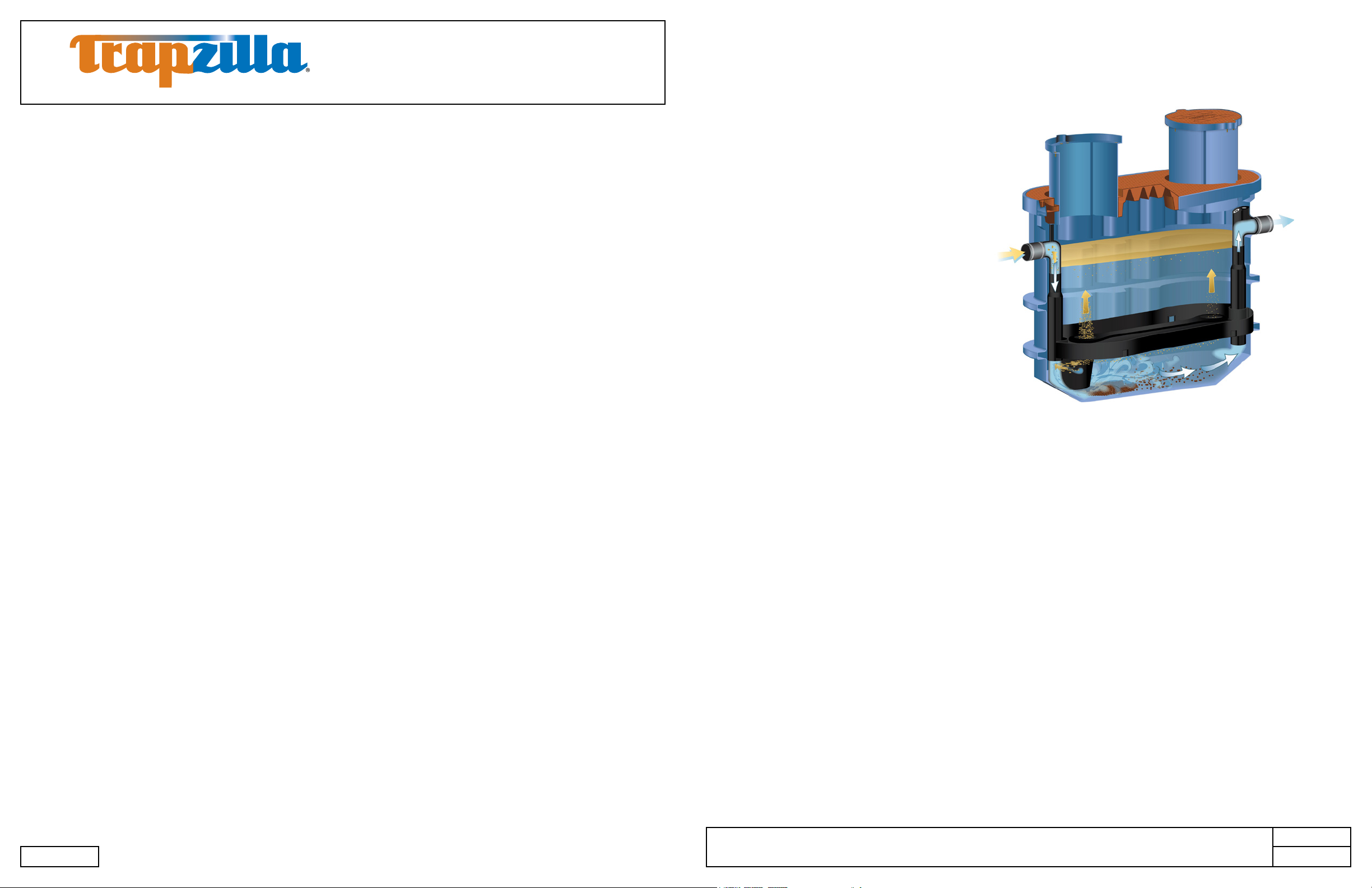
1. System Overview
The Thermaco, Inc. Trapzilla® Supercapacity
Grease Interceptor collects free-floating
grease & oils contained in kitchen drain water
ows. As most food service facility managers
already know, grease buildup inside a
building’s grease containment system is a
major cause of problems due to exterior drain
line blockages. These problems jeopardize
normal operations as well as create health
and safety hazards within the facility itself.
The proper installation of a Trapzilla®
Supercapacity Grease Interceptor can
reduce or eliminate grease problems and
costly sewer surcharges and nes through
efcient separation and retention of freeoating grease & oils.
3.3.1 One TZ-1826 ......................................................................................................................... 8
3.3.2 Installing Multiple Trapzilla Units in Parallel ........................................................................... 9
3.3.3 Installing Multiple Trapzilla Units in Series ............................................................................. 10
4. Above-Ground Installation ...................................................................................................................... 11
4.1 Components for Above-Ground Installations .................................................................................. 11
4.2 Instructions for Assembling and Attaching External Brace ............................................................. 12
4.3 Instructions for Installing Multiple Trapzilla Units Above-Ground .................................................... 12
4.3.1 Installing TZ-1826-SSA with TSS-95-SSA in Series .............................................................. 12
4.3.2 Construction of Riser for TSS-95-SSA installation in series with TZ-1826-SSA .................... 13
4.3.3 Installing Multiple TZ-1826-SSA in Series ............................................................................. 13
4.3.4 Installation of Pipe Hangers with Above-Ground Units .......................................................... 14
5. In-Ground Installation Instructions .......................................................................................................... 15
5.1 Single TZ-1826 Installed In-Ground ............................................................................................... 15
5.2 TZ-1826 with Optional ECA-TZ-29 Extension Collars .................................................................... 16
5.3 Concrete Specications for In-Ground Installation ......................................................................... 17
5.4 Concrete Calculations for TZ-1826 Models/Components* ............................................................. 17
5.5 Trimming and Setting the ECA-TZ-18 Single-Piece Extension Collar ............................................ 18
The Trapzilla offers patented at separation
curve technology. This means that the unit does not lose grease separation efciency as it lls with
retained grease. Thus, the Trapzilla stores large quantities of grease without losing efciency. The
unique compact design of the Trapzilla allows for installation into most facilities. Options are available
that enable a Trapzilla unit to be installed on the oor, suspended from the ceiling or in-ground outside
the facility.
Trapzilla units are designed to treat high ows of kitchen drainwater with large grease storage capacity
within a small footprint unit. These units are easy to maneuver into position and just as easy to plumb.
Hydromechanical grease interceptors, automatic recovery units, grease removal devices and other
similar plumbing devices receiving kitchen ows from sinks, oor drains, woks and other food bearing
sources may generate odors. There are many factors inuencing odor evolution and dissemination.
These include room ventilation, kitchen menu, ambient temperatures, ware washing practices, grease/oil
input, daily input uid volume, sanitizers, installation plumbing design and product maintenance/upkeep.
Odors are usually prevented by good area ventilation, frequent uid inputs, good product maintenance
practices and proper product installation. Additional steps, including aeration, chlorination, pH control,
improved area ventilation and additional maintenance may be needed at some sites.
*Devices formerly referred to as grease traps are now called hydromechanical grease interceptors.
6. Unit Maintenance.................................................................................................................................... 20
6.1 Measuring Grease/Solids Levels .................................................................................................... 20
6.2 Pumping/Servicing Unit .................................................................................................................. 21
7. Limited Warranty and Remedy ............................................................................................................... 22
MNL-TZ-1826 2
©2018 Thermaco, Inc. All rights reserved • Patented/Patents Pending • Specications subject to change without notice
Thermaco, Inc. • 646 Greensboro St. • Asheboro, N. C. 27204-2548 • (336) 629-4651
AEF
MNL-TZ-1826 3
Trapzilla® Grease Interceptor
1
2
3
1
2
3
1
2
3
1
2
3
4
1
2
3
Installation and Operations Manual
A THERMACO® Technology
2. Models and Options
Thermaco offers different models and options specically designed to assist the owner/installer meet
site conditions while complying with local pretreatment and plumbing code.
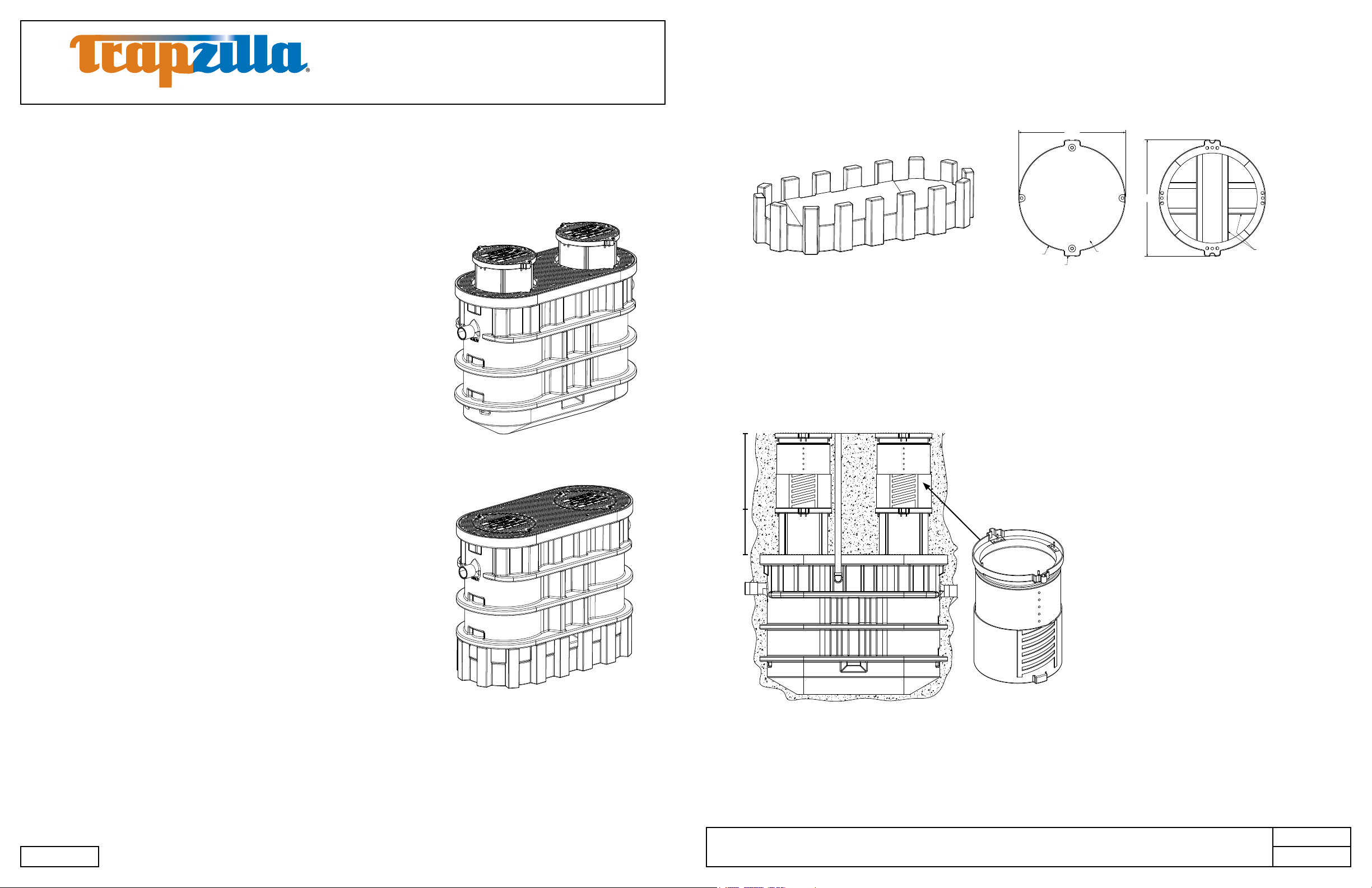
2.1 Models
TZ-1826
1,826 pounds of grease storage, PDI and ASME rated
at 100 gpm. Equipped with 4” inlet/outlet, 2” vessel vent
connection, and 4” Low-Head Flow Control Accessory to
limit ow to 100 gpm.
Comes with: Extension Collar Adapter Lid Assembly with
two 18” tall extension collars and two 22” diameter lids.
TZ-1826 Models
2.2 Options (Some options must be purchased separately)
Top View
21.13 in
[53.7 cm]
R10.56 in
[26.8 cm]
R11.56 in
[29.4 cm]
SSA-1826
Support Stand for TZ-1826 for Above-Ground
Installations. Must be fully supported, not to
be installed over grates.
*Included with TZ-1826-SSA Models
Optional 22” diameter cover available for
In-Ground installations. Provides a non-slip,
diamond patterned aluminum replacement for
the standard STC-22 cover. Each TZ-1826
would require two (2) FTCA-22 covers.
DIAMOND PLATE SURFACE
FTCA-22
23.10 in
[58.7 cm]
Bottom View
ANGLE STIFFENERS
ECA-TZ-29
(purchase separately)
ECA-TZ-29
TZ-1826-SSA
1,826 pounds of grease storage, PDI and ASME rated
at 100 gpm. Equipped with 4” inlet/outlet, 2” vessel vent
connection, and 4” Low-Head Flow Control Accessory to
limit ow to 100 gpm.
Comes with: Extension Collar Adapter Lid Assembly with
two 18” tall extension collars, two 22” diameter lids,external
brace (not pictured) and SSA-1826 Support Stand.
*Models available with 6” Inlet/Outlet, add sufx -6 to model.
Extension
0-18” Built-In
Optional, eld-modiable extension
collars available to provide
additional depth for existing kitchen
drainage piping.
• TZ-1826-ECA Models ship with
two (2) built-in 0-18” extension
collars.
• ECA-TZ-29 adds 0-29” depth
to -ECA model.
• Contact Thermaco before
installing any Trapzilla more
than 60” below grade from
center of outlet pipe or in
location where water table will
ever rise above bottom of unit.
MNL-TZ-1826 4
©2018 Thermaco, Inc. All rights reserved • Patented/Patents Pending • Specications subject to change without notice
Thermaco, Inc. • 646 Greensboro St. • Asheboro, N. C. 27204-2548 • (336) 629-4651
AEF
MNL-TZ-1826 5
Trapzilla® Grease Interceptor
1
2
3
Installation and Operations Manual
A THERMACO® Technology
3. Plumbing Installation
3.1 Plumbing Considerations Prior to Installation
3.1.1 Locating the Unit
The system should be visible and easily accessible for maintenance and inspection. Options are available
to install the Trapzilla in a basement, suspended from a ceiling or in-ground in an exterior location. Make
sure adequate room is provided around the unit to allow easy access for a pump truck operator. Make
sure the height above the Trapzilla access cover is enough to properly service the system.
3.1.2 Inlet/Outlet Piping
The inlet and outlet piping connections require exible sleeve pipe couplings. Keep outlet piping as
straight as possible. Thermaco, Inc. recommends installation of Two-Way Cleanouts on both the Inlet and
Outlet of Trapzilla Interceptors and Solids Separators in accordance with all applicable laws, regulations
and codes. These cleanouts should match the size of the Inlet and Outlet Piping (i.e. for 4” Inlet/
Outlet piping, a 4” cleanout should be used). Use only “sweep” connections. Do not reduce the pipe
sizing on the outlet piping. Do not install “P” trap on outlet connection of system. (Note: The system
already has a internal gas trap)
TZ-1826 Models
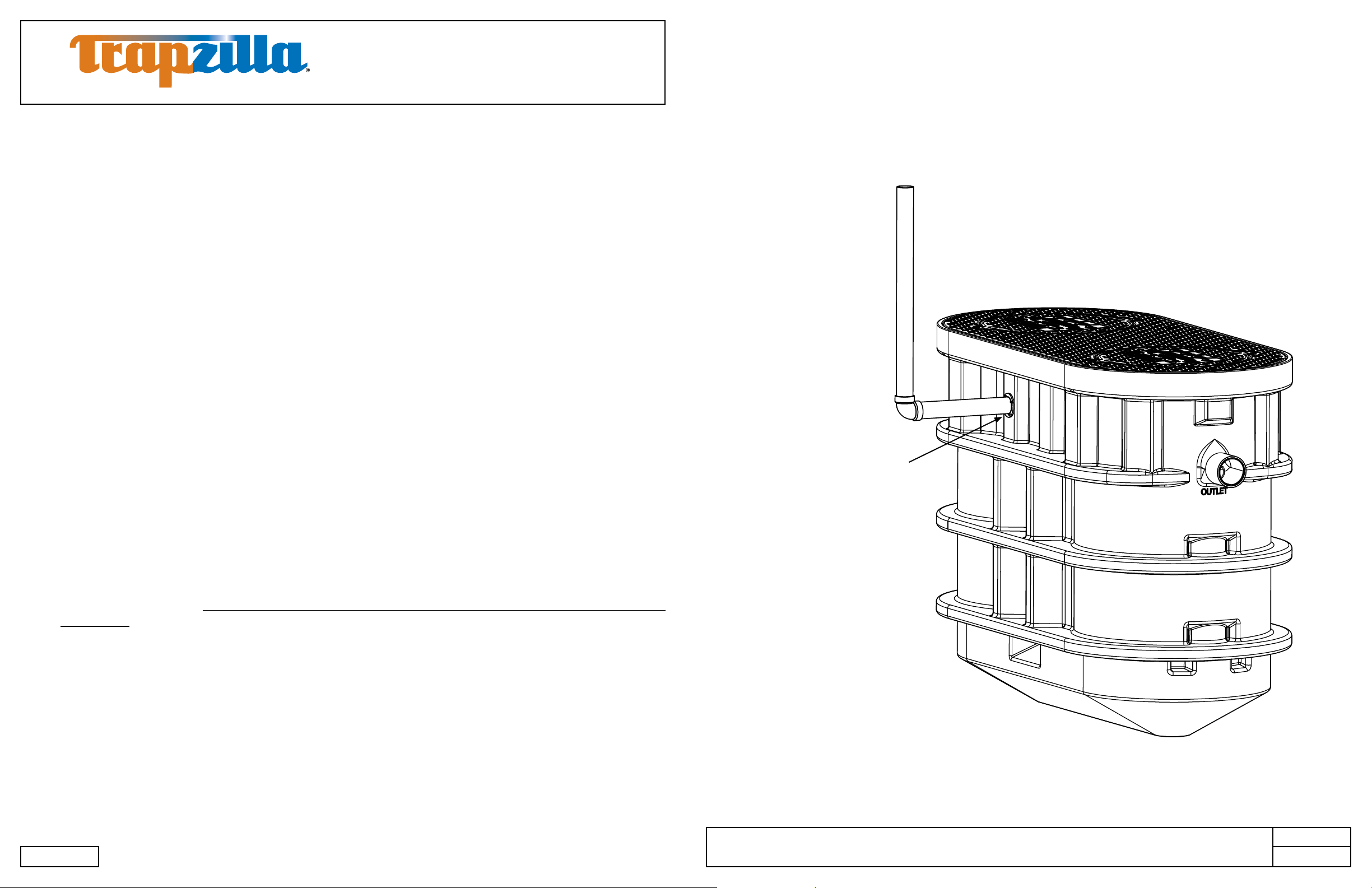
3.2 Vessel Vent Connection
Venting of the Trapzilla tank is recommended by the manufacturer and required for in-door installations.
• Vent the tank through the provided 2” NPT threaded connector on the side of the tank (This vent may
be located above the outlet or on the side of the tank depending on model).
• Remove and discard the plug and connect appropriate vent lines as indicated below (for 2” vent
connection, use 2” pipe).
3.1.3 Flow Controls
Trapzilla systems are supplied with a Low-Head Flow Control module (LHFC). This should be connected
to the inlet of the Trapzilla unit in situations where ow rate needs to be restricted to the ASME rated
ow or when vented ow control is required by local code.
3.1.4 Venting the Outlet
An outlet vent or approved air admittance valve of at least 1/2 the diameter of the system’s outlet
connection must be present as close as possible to the Trapzilla outlet to prevent possible siphonage
problems. The Vent on the Outlet piping is to be installed in accordance with all applicable laws,
regulations and codes. Failure to provide a vent for the system voids Thermaco’s Limited Warranty for
the system.
3.1.5 High Head Height Applications Over Six (6) Feet (1.95 m)
For installations where there is head height of greater than 6 feet (1.95 meters), Thermaco, Inc.
recommends installation of a code-approved Vented Flow Control Assembly (Thermaco VFCA not
included with Trapzilla).
Vessel Vent Connection
Can be connected to the outlet vent,
facility vent, or independently vented to
atmosphere
Note: Drawing for reference only. Equipment must be installed in compliance with all applicable laws, regulations
and codes, including plumbing codes. Installation should be performed by a qualied plumber.
MNL-TZ-1826 6
©2018 Thermaco, Inc. All rights reserved • Patented/Patents Pending • Specications subject to change without notice
Thermaco, Inc. • 646 Greensboro St. • Asheboro, N. C. 27204-2548 • (336) 629-4651
AEF
MNL-TZ-1826 7
 Loading...