

Thermablaster WDFT060-VF-IR, WNT060-VF-IR, WDFT100-VF-IR, WNT100-VF-IR, WDFT250-VF-IR User Manual
...
WARNING: This appliance is equipped for
(Natural and/or Propane) gas. Field
conversion is not permitted other than
between natural or propane gases in dual
fuel models only.
Vent-Free Gas Wall Heater
WNT060/100/250-VF-IR (NATURAL GAS)
WLT060/100/250-VF-IR (PROPANE GAS)
CAUTION - FOR YOUR SAFETY
INSTALLER: Leave this manual with the appliance
CONSUMER: Retain this manual for future reference
This is an unvented gas-fired heater. It uses air (oxygen) from the room in
which it is installed. Provisions for adequate combustion and ventilation
air must be provided. Refer to Air For Combustion and Ventilation
section on page 8 of this manual. Warranty is void if not professionally installed.
This appliance may be installed in an aftermarket, permanently located,
manufactured (mobile) home, where not prohibited by local codes.
This appliance is only for use with propane or natural gas.
This appliance is equipped with a simple means to switch between
propane and natural gas in dual fuel models only. Field conversion by
any other means including the use of a kit is not permitted.
Conforms to ANSI Z21.11-2b-2013. Gas-Fi red Room Heater Volume II, Unvented Room Heater
1
MODEL: WDFT060/100/250-VF-IR (DUAL FUEL)
Reecon North America
1090 Freeport Road
Pittsburgh, PA 15238
nd
2
Floor

PRODUCT SPECIFICATIONS
Model WDFT060-VF-IR WDFT100-VF-IR WDFT250-VF-IR
BTU(available)
Gas type Using natural gas Using natural gas Using natural gas
Press regulator setting 4 in w.c. 4 in w.c. 4 in w.c.
Inlet gas pressure (inches of water) for purpose of input adjustment
Maximum 7 in w.c. 7 in w.c. 7 in w.c.
Minimum 5 in w.c. 5 in w.c. 5 in w.c.
Gas type Using propane gas Using propane gas Using propane gas
Press regulator setting 11 in w.c. 11 in w.c. 11 in w.c.
inlet gas pressure (inches of water) for purpose of input adjustment
Maximum 14 in w.c. 14 in w.c. 14 in w.c.
Minimum 11 in w.c. 11 in w.c. 11 in w.c.
Ignition Electric Piezo Electric Piezo Electric Piezo
6000 10000 25000
Dimension inches
(H×W×D)
15.7×7.5×25.6 18.1×7.5×28.7 30.7×9.1×29.5
Important Note:
1) An unvented room heater having an input rating of more than 10,000 Btu/hr
(2,931 W) shall not be installed in a bedroom or bathroom; or
2) An unvented room heater having an input rating of more than 6000 Btu/hr
(1,758 W) shall not be installed in a bathroom.
2

Model WNT060-VF-IR WNT100-VF-IR WNT250-VF-IR
BTU(available)
Gas type natural gas natural gas natural gas
Press regulator setting 4 in w.c. 4 in w.c. 4 in w.c.
Inlet gas pressure (inches of water) for purpose of input adjustment
Maximum 7 in w.c. 7 in w.c. 7 in w.c.
Minimum 5 in w.c. 5 in w.c. 5 in w.c.
Ignition Electric Piezo Electric Piezo Electric Piezo
Dimension inches
(H×W×D)
6000 10000 25000
15.7×7.5×25.6 18.1×7.5×28.7 30.7×9.1×29.5
Model WLT060-VF WLT100-VF WLT250-VF-IR
BTU(available)
6000 10000 25000
Gas type LP LP LP
Press regulator setting 11 in w.c. 11 in w.c. 11 in w.c.
inlet gas pressure (inches of water) for purpose of input adjustment
Maximum 14 in w.c. 14 in w.c. 14 in w.c.
Minimum 11 in w.c. 11 in w.c. 11 in w.c.
Ignition Electric Piezo Electric Piezo Electric Piezo
Dimension inches
(H×W×D)
15.7×7.5×25.6 18.1×7.5×28.7 30.7×9.1×29.5
3

1. IMPORTANT SAFETY INFORMATION
IMPORTANT: Read this owner’s manual carefully and completely before trying to assemble, operate, or
service this heater. Improper use of this heater can cause serious injury or death from burns, fire,
explosion, electrical shock, and carbon monoxide poisoning. Only a qualified installer, service agent, or
local gas supplier may install and service this product.
WARNING: Do not store or use gasoline or other flammable vapors and liquids in the vicinity of this
or any other appliance.
CARBON MONOXIDE POISONING: Early signs of carbon monoxide poisoning resemble the flu with
headache, dizziness and/or nausea. If you have these signs, heater may not be working properly. Get
fresh air at once! Have heater serviced. Some people - pregnant women, persons with heart or lung
disease, anemia, those under the influence of alcohol, those at high altitude - are more affected by
carbon monoxide than others.
Natural and Propane /LP Gas: Natural and Propane/LP gas are odorless. An odor-producing agent is
added to the gas. The odor helps you detect a gas leak. However, the odor added to the gas can fade.
Gas may be present even though no odor exists.
WARNING: Any change to this heater or its controls can be dangerous.
WARNING: Do not use any accessories not approved for use with this heater.
WARNING: Carefully supervise young children when they are in the room with the heater.
WARNING: Make sure grill guard is in place before running heater.
WARNING: Keep the appliance area clear and free from combustible materials, gasoline, and other
flammable vapors and liquids.
WARNING: Due to high temperatures, the appliance should be located out of traffic and away from
furniture and draperies.
WARNING: Heater becomes very hot when running. Keep children and adults away from hot
surfaces to avoid burns or clothing ignition. Heater will remain hot for a time after shutoff. Allow
surfaces to cool before touching.
WARNING: Do not place clothing or other flammable material on or near the appliance. Never place
any objects in the heater.
WARNING: Failure to keep the primary air opening(s) of the burner(s) clean may result in sooting
and property damage.
WARNING: Do not allow fans to blow directly towards the heater. Avoid any drafts that alter burner
flame patterns.
WARNING: Do not use a blower insert, heat exchanger insert or other accessory not approved for
use with this heater
WARNING: Failure to position the parts in accordance with these diagrams or failure use only parts
specifically approved with this heater may result in property damage or personal injury.
4

CAUTION: Two gas line installations at the same time are prohibited. The access plate to the simple
switching means on the dual fuel models shall not be opened while the heater is in operation.
1. This heater shall not be installed in a room or space unless the required volume of indoor combustion
air is provided by the method described in the National Fuel Gas Code, ANSI Z223.1/NFPA 54, the
International Fuel Gas Code, or applicable local codes.
2. Do not place Propane/LP supply tank(s) inside any structure. Propane/LP supply tank(s) must be
placed outdoors.
3. This heater shall not be installed in the place which the strong wind would shut down the appliance.
4. This heater needs fresh air ventilation to run properly. This heater has an Oxygen Depletion Sensing
(ODS) safety shutoff system. The ODS shuts down the heater if not enough fresh air is available. See Air
for Combustion and Ventilation, pages 6 through 9. If heater keeps shutting off, see Troubleshooting.
5. Keep all air openings in front and bottom of heater clear and free of debris. This will ensure enough air
for proper combustion.
6. If heater shuts off, do not relight until you have provided fresh air from outside. If heater keeps shutting
off, have it serviced.
7. Do not run heater where flammable liquids or vapors are used or stored under dusty conditions.
8. Before using furniture polish, wax, carpet cleaner, or similar products, turn heater off. If heated, the
vapors from these products may create a white powder residue within burner box or on adjacent walls or
furniture.
9. Always run heater with control knob at PILOT/IGN, LOW or HIGH locked positions. Never set control
knob between locked positions, otherwise poor combustion and higher levels of carbon monoxide may be
resulted.
10. Do not use this room heater if any part has been under water. Immediately call a qualified service
technician to inspect the room heater and to replace any part of the control system and any gas control
which has been under water.
11. Turn off and let heater cool down before servicing. Only a qualified service person should service and
repair heater.
12. Periodic visual check of pilot and burner flame, with pictorial sketches or drawings.
13. The appliance must be isolated from the gas supply piping system by closing its equipment shut-off
valve during any pressure testing of the gas supply piping system at test pressures equal to or less
than 1/2 psi (3.5 kPa).
QUALIFIED INSTALLING AGENCY
Only a qualified agency should install and replace gas piping, gas utilization equipment or
5

accessories, repair and service the heater. The term “qualified agency” means any individual, firm,
corporation, or company that either in person or through a representative is engaged in and is
responsible for:
a.) Installing, testing, or replacing gas piping or
b.) Connecting, installing, testing, repairing, or servicing equipment; that is experienced in such work; that
is familiar with all precautions required; and that has complied with all the requirement of the authority
having jurisdiction.
2 PRODUCT FEATURES
SAFETY PILOT
This heater has a pilot with an Oxygen Depletion Sensing (ODS) safety shutoff system. The ODS/pilot
shuts off the heater if there is not enough fresh air.
PIEZO IGNITION SYSTEM
This heater is equipped with a piezo igniting system. No power supply required.
GAS OPTIONS CAPABLE (Dual Fuel Models Only) (Models that start with WDFT)
If you have the dual fuel model, your heater is equipped to operate on either Propane or Natural gas. The
heater is shipped from the factory ready for connecting to Propane. The heater can easily be changed to
Natural gas by having your qualified installer follow the instructions and the markings on the heater.
THERMOSTATIC CONTROL
These heaters have a control valve with a thermostat sensing bulb. This results in the greatest heater
comfort and may result in lower gas bills.
LOCAL CODES
Install and use heater with care. Follow all local codes. In the absence of local codes, use the latest
edition of The National Fuel Gas Code, ANSI Z223.1/ NFPA 54.
3. Preparing for installation
Before beginning assembly or operation of the product, make sure all parts are present. Compare parts
with package contents list and diagram above. If any part is missing or damaged, do not attempt to
assemble, install or operate the product. Contact customer service for replacement parts.
6

Before installing heater, make sure you have the items listed below:
Plaque plates
Igniter button
Control knob
NAT and LP
gas conversion
(WDFT only)
Grill
Figure 1 - Vent-Free Gas Heater Infrared
UNPACKING
1. Remove heater from carton.
2. Remove all protective packaging applied to heater for shipping
3. Check heater for any shipping damage. If heater is damaged, promptly inform dealer where you bought
heater.
4. WATER VAPOR: A BY-PRODUCT OF UNVENTED ROOM HEATERS
Water vapor is a by-product of gas combustion. An unvented room heater produces approximately one (1)
ounce (30 ml) of water for every 1,000 BTUs (0.3 KWs) of gas input per hour. Unvented room heaters are
recommended as supplemental heat (a room) rather than a primary heat source (an entire house). In
most supplemental heat applications, the water vapor does not create a problem. In most applications,
the water vapor enhances the low humidity atmosphere experienced during cold weather. The following
steps will help ensure that water vapor does not become a problem.
1. Be sure the heater is sized properly for the application, including ample combustion air and circulation
air.
2. If high humidity is experienced, a dehumidifier may be used to help lower the water vapor content of
the air.
3. Do not use an unvented room heater as the primary heat source.
5. AIR FOR COMBUSTION AND VENTILATION
WARNING: This heater shall not be installed in a confined space or unusually tight construction
unless provisions are provided for adequate combustion and ventilation air. Read the following
instructions to ensure proper fresh air for this and other fuel-burning appliances in your home.
Providing Adequate Ventilation
This heater shall not be installed in a room or space unless the required volume of indoor combustion air
is provided by the method described in the NATIONAL FUEL GAS CODE, ANSI Z223.1/NFPA 54, the
INTERNATIONAL FUEL GAS CODE, or applicable local codes.The following are excerpts from National
Fuel Gas Code, ANSI Z223.1/ NFPA 54. Air for Combustion and Ventilation. All spaces in homes fall into
one of the three following ventilation classifications:
1. Unusually Tight Construction
Igniter button Igniter button
7

2. Unconfined Space
3. Confined Space
The information on the followed pages will help you classify your space and provide adequate ventilation.
Confined and Unconfined Space
The National Fuel Gas Code, ANSI Z223 .1/NFPA 54 defines a confined space as a space whose volume
is less than 50 cu. ft. per 1,000 BTU/hr (4.8 m3 per kw) of the aggregate input rating of all appliances
installed in that space and an unconfined space as a space whose volume is not less than 50 cubic feet
per 1,000 BTU/hr (4.8 m3 per kw) of the aggregate input rating of all appliances installed in that space.
Rooms connecting directly with the space in which the appliances are installed, through openings not
furnished with doors, are considered a part of the unconfined space.
This heater shall not be installed in a confined space or unusually tight construction unless provisions are
provided for adequate combustion and ventilation air. Adjoining rooms are connecting only if there are
odorless passageways or ventilation grills between them.
Unusually Tight Construction
The air that leaks around doors and windows may provide enough fresh air for combustion and ventilation.
However, in buildings of unusually tight construction, you must provide additional fresh air. Unusually
tight construction is defined as construction where:
a) Walls and ceilings exposed to the outside atmosphere have a continuous water vapor retarder with a
rating of one perm (6×10-11kg per pa-sec-m2) or less with openings gasket or sealed and
b) Weather stripping has been added on openable windows and on doors and
c) Caulking or sealants are applied to areas such as joints around window and door frames, between sole
plates and floors, between wall ceiling joints, between wall panels, at penetrations for plumbing, electrical,
and gas lines, and at other openings.
If your home meets all of the three criteria above, you must provide additional fresh air. See “Ventilation
Air From Outdoors”. If your home does not meet all of the three criteria above, proceed to “Determining
Fresh-Air Flow For Heater Location”.
6. DETERMINING FRESH-AIR FLOW FOR HEATER LOCATION
Using this worksheet to determine if you have a confined or unconfined space. Space: Includes the room
in which you will install heater plus any adjoining rooms with doorless passageways or ventilation grills
between the rooms.
1. Determine the volume of the space Length × Width × Height = cu. ft. (volume of space)
Example: Space size 20 ft. (length) × 16 ft. (width)×8 ft. (ceiling height) =2560 cu. ft. (volume of space) If
additional ventilation to adjoining room is supplied with grills or openings, add the volume of these rooms
to the total volume of the space.
2. Divide the space volume by 50 cubic feet to determine the maximum BTU/hr the space can support.
(volume of space) ÷ 50 cu. ft. =(Maximum BTU/hr the space can support)
8

3. Add the BTU/hr of all fuel burning appliances in the space.
Vent-free heater BTU/hr
Gas water heater* BTU/hr
Gas furnace BTU/hr
Vented gas heater BTU/hr
Gas heater logs BTU/hr
Other gas appliances* + BTU/hr
Total = BTU/hr
Example:
Gas water heater 30,000 BTU/hr
Vent-free heater + 26,000 BTU/hr
Total = 56,000 BTU/hr
*Do not include direct-vent gas appliances. Direct-vent draws combustion air from the outdoors and vents to the outdoors
4. Compare the maximum BTU/hr the space can support with the actual amount of
BTU/hr used
BTU/hr (maximum the space can support)
BTU/hr (actual amount of BTU/hr used)
Example : 51,200 BTU/hr (maximum the space can support)
56,000 BTU/hr (actual amount of BTU/hr used)
The space in the above example is a confined space because the actual BTU/hr used is more than the
maximum BTU/hr the space can support.
You must provide additional fresh air. Your options are as follows:
Rework worksheet, adding the space of an adjoining room. If the extra space provides an unconfined
space,
a) remove door to adjoining room or add ventilation grills between rooms. See “Ventilation Air From
Inside Building ” on next page.
b)Vent room directly to the outdoors. See “Ventilation Air From Outdoors ” on next page.
c) Install a lower BTU/hr heater if lower BTU/hr size makes room unconfined. If the actual BTU/hr used is
less than the maximum BTU/hr the space can support, the space is an unconfined space. You will need
no additional fresh air ventilation.
WARNING: If the area in which the heater may be operated is smaller than that defined as an
unconfined space or if the building is of unusually tight
construction, provide adequate combustion and ventilation air by
one of the methods described in the National Fuel Gas Code,
ANSI Z223.1/NFPA 54. Air for Combustion and Ventilation, or
applicable local codes.
WARNING: If the area in which the heater may be
operated does not meet the required volume for indoor
combustion air, combustion and ventilation air shall be
provided by one of the methods described in the National
Fuel Gas Code, ANSI Z223.1/NFPA 54, the International Fuel
Gas Code, or applicable local codes.
9

Ventilation Air From lnside Building
This fresh air would come from an adjoining unconfined space. When ventilating to an adjoining
unconfined space, you must provide two permanent openings: one within 12 inches of the ceiling and one
within 12 inches of the floor on the wall connecting the two spaces (see options 1 and 2, Figure 2). You
can also remove the door into adjoining room (see option 3, Figure 2). Follow the National Fuel Gas Code.
ANSI Z223.1/NFPA 54, Air for Combustion and Ventilation for required size of ventilation grills or ducts.
Figure 2 - Ventilation Air from Inside Building
NOTE: Base not included. Not for use in bedrooms or bathrooms.
Ventilation Air From Outdoors
Provide extra fresh air by using ventilation grills or ducts. You
must provide two permanent openings: one within 12 inches of
the ceiling and one within 12 inches of the floor. Connect these
items directly to the outdoors or spaces open to the outdoors.
These spaces include attics and crawl spaces. Follow the
National Fuel Gas Code, ANSI Z223.1/ NFPA 54, Air for
Combustion and Ventilation for required size of ventilation grills
or ducts.
Figure 3 - Ventilation Air from Outdoors
IMPORTANT: Do not provide openings for inlet or outlet air into attic if attic has a
thermostat-controlled power vent. Heated air entering the attic will activate the power vent. Rework
worksheet, adding the space of the adjoining unconfined space. The combined spaces must have
enough fresh air to supply all appliances in both spaces.
7. INSTALLATION
NOTICE: This heater is intended for use as supplemental heat. Use this heater along with your
primary heating system. Do not install this heater as your primary heat source. If you have a central
heating system, you may run system’s circulating blower while using heater. This will help circulate the
heat throughout the house. In the event of a power outage, you can use this heater as your primary heat
source.
Caution: If you install the heater in a home garage:
Heater pilot and burner must be at least 18 inches above the floor. Place heater where moving
vehicle will not hit it.
WARNING: A qualified service person must install heater. Follow all local codes.
WARNING: Never install the heater
in a recreational vehicle
where curtains, furniture, clothing, or other flammable objects are less than 36 inches from the
front, top, or sides of the heater
in high traffic areas
in windy or drafty areas
10

CAUTION: This heater creates warm air currents. These
currents move heat to wall surfaces next to heater.
Installing heater next to vinyl or cloth wall coverings or
operating heater where impurities (such as tobacco smoke,
aromatic candles, cleaning fluids, oil or kerosene lamps, etc.)
in the air exist, may cause walls to discolor.
IMPORTANT: Vent-free heaters add moisture to the air.
Although this is beneficial, installing heater in rooms without
enough ventilation air may cause mildew to form too much
moisture. See Air for Combustion and Ventilation.
Figure 4 Mounting clearances
from combustibles as
viewed from front of heater (inches)
Check Gas Type
Be sure your gas supply is right for your heater. Otherwise, call dealer where you bought the heater from
for proper type heater.
Clearances to Combustibles
Carefully follow the instructions below. This heater is a freestanding unit designed to be mounted on a wall.
WARNING: Maintain the minimum clearances shown in Figure 4. If you can, provide greater
clearances from floor, ceiling, and joining wall.
LOCATING HEATER
This heater is designed to be mounted on a wall. For convenience and efficiency, install heater:
1) where there is easy access for operation,
inspection, and service.
2) In the coldest part of room.
MOUNTING HEATER TO WALL
1. Mounting the Bracket
Mounting the attached bracket with folding anchor on desired location
2. Hanging the heater on the bracket, simply finished.
Figure 5 - Mounting holes Location
Figure 6 Mounting on wall 060/100-VF Figure 7 Mounting on wall 320-VF
11
8. CONNECTING TO GAS SUPPLY
WARNING: A qualified service technician must connect heater to gas supply. Follow all local codes.
WARNING: This appliance requires a 3/8-inch NPT (National Pipe Thread) inlet connection to the
pressure regulator.
WARNING: Never connect heater to private (non-utility) gas wells. This gas is commonly known as
wellhead gas.
WARNING: Do not over-tighten gas connections.
CAUTION: Use only new, black iron or steel pipe. Internally tinned copper tubing may be used in
certain areas. Check your local codes. Use pipe of 1/2-in. diameter or greater to allow proper gas
volume to heater. If pipe is too small, undue loss of pressure will occur.
NATURAL GAS MODELS:
CAUTION: Check your gas line pressure before connecting heater to gas line. Gas line pressure
must be no greater than 11 inches of water. If gas line pressure is higher, damage on appliance
regulator could occur.
PROPANE MODELS:
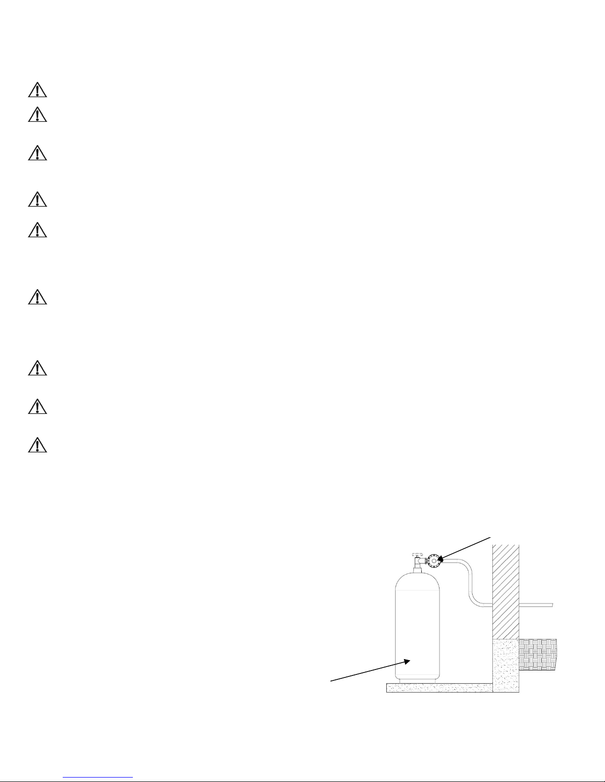
CAUTION: Never connect heater directly to the gas supply. This heater requires an external
regulator (not supplied). Install the external regulator between the heater and gas supply.
CAUTION: Avoid damage to regulator. Hold gas regulator with wrench when connecting into gas
piping and/or fittings.
CAUTION: Use pipe joint sealant that is resistant to gas (Propane or Natural Gas).
IMPORTANT: Install an equipment shutoff valve in an accessible location where the gas pipe goes
indoors. The equipment shutoff valve is for turning on or shutting off the gas to the appliance.
Apply pipe joint sealant lightly to male threads. This will prevent
excess sealant from going into pipe. Excess sealant in pipe could
result in clogged heater valves. The installer must supply an
external regulator. The external regulator will reduce incoming gas
pressure. You must reduce incoming gas pressure to between 11
and 14 inches of water. If you do not reduce incoming gas
pressure, appliance regulator damage could occur. Install external
regulator with the vent pointing down as shown in Figure 8.
Pointing the vent down protects it from freezing rain or sleet.
Propane/LP supply tank
Figure 8 - External Regulator with Vent Pointing Down
12
External regulator

C
h
e
r
r
e
C
a
c
f
u
t
n
i
a
w
r
l
a
e
U
l
r
e
e
e
u
p
e
g
c
t
o
9
,
h
t
a
y
t
n
p
3
i
a
e
p
n
a
e
n
e
a
e
e
m
l
e
a
c
a
c
i
a
t
p
i
p
e
w
e
r
o
n
i
h
O
s
e
o
h
Heat
requi
or se
conn
r is pre-se
ed for con
vice techn
cting to n
a qu
metal
For
dual
lified instal
hex plug
hanging f
uel mode
1)
Before g
2)
For NAT
AUTION:
eater is r
AUTION:
screw. (s
the knob
selection
NOT ope
Two gas li
nning.
at factory
ecting to
cian can p
tural gas s
To avoid
ler or servi
ith sealan
om propa
s only):
s conversi
e Figure
RAL GAS
ocks into t
valve mus
ate the he
nes install
for propan
ropane. O
rform gas
upply.
as leakag
e technici
.
ne to natu
n, remov
.1)
turn knob
e NG posi
be locked
ter betwe
tion at the
gas; no
ly a qualif
selection
at the inle
n must us
ral gas su
knob lock
counterclo
tion (see F
in the NG
n the lock
same time
hanges ar
ed installe
nd
of regulat
e steel or
ply (WDF
by removi
ckwise unt
gure 9.) T
osition. D
d position
is forbidd
r,
T
g
l
e
.
n. Do not t
he open c
F
igure 9
ver while t
e
3)
Remov
regulato
is in the
4)
Remov
cap (Se
5)
Turn it o
reinstall
Make s
installed
the cap b
r and now
LP positio
the white
Figure 9.
ver (See F
it on the c
re the whit
on the ca
hand fro
he white p
(See Figu
lastic scr
).
gure 9.4)
p (See Fig
plastic s
tightly.
6)
Replace
the cap o
the regul
the
astic scre
re 9.2).
w from the
nd
ure 9.5).
rew is
tor.
13
Figu
re 9.1

7)
s
c
s
P
.
o
s
o
u
S
R
u
o
b
k
i
9
9
9
s
n
e
n
O
a
s
After ga
conversi
n, make s
re to repla
ce
knob lo
8)
Reverse
supply to
For PRO
Figure 9)
k and the
teps 1 thr
propane s
ANE GA
Reverse
crew.
ugh 7 to c
pply:
, turn kno
egulator c
nvert bac
clockwise
p as prev
Figure
to LP ga
until the k
ously don
.3
if needed.
ob locks i
in steps 3
For chang
to the PR
through 6.
ing from n
PANE po
tural gas
ition (see
Figure
Figure
.4
.5
14

CHECKING GAS CONNECTIONS
WARNING: Test all gas piping and connections for leaks after installing or servicing. Correct all
leaks at once.
WARNING: Never use an open flame to check for a leak. Apply a mixture of liquid soap and water to
all joints. If bubbles form, there is a leak. Correct all leaks at once.
Presure Testing Gas Suply Piping System
Test Pressures In Excess Of 1/2 PSIG (3.5kPa)
1. Disconnect heater with its appliance main gas valve (control valve) and equipment shutoff valve from
gas supply piping system. Pressures in excess of 1/2 PSIG will damage heater regulator.
2. Cap off open end of gas pipe where equipment shutoff valve was connected.
3. Pressurize supply piping system by either using compressed air or opening gas supply valve.
4. Check all joints of gas supply piping system. Apply mixture of liquid soap and water to gas joints. If
bubbles form, there may be a leak.
5. Correct all leaks at once.
6. Reconnect heater and equipment shutoff valve to gas suply. Check reconnected fittings for leaks.
Test Pressures Equal To or Less Than 1/2 PSIG (3.5 kPa)
1. Close equipment shutoff valve
2. Pressurize supply piping system by either using compressed air or opening natural supply tank valve.
3. Check all joints from gas meter to equipment shutoff valve. Apply mixture of liquid soap and water to
gas joints. If bubbles form, there is a leak.
4. Correct all leaks at once.
Pressure Testing Heater Gas Connections
1. Open equipment shutoff valve.
2. Open gas supply tank valve.
3. Make sure control knob of heater is in the OFF position.
4 Check all joints from equipment shutoff valve to control valve. Apply mixture of liquid soap and water to
gas joints. If bubbles form, there may be a leak.
5. Correct all leaks at once.
15

9. OPERATION
FOR YOUR SAFETY READ BEFORE LIGHTING
WARNING: If you do not follow these instructions exactly, a fire or explosion may result causing
property damage, personal injury or loss of life.
1) When lighting the pilot, follow these instructions exactly.
2) BEFORE LIGHTING, smell all around the appliance area for gas. Be sure to smell next to the floor
because some gas is heavier than air and will settle on the floor.
3) Use only your hand to push in or turn the gas control knob. Never use tools. If the knob will not push in
or turn by hand, don’t try to repair it, call a qualified service technician or gas supplier. Forced or
attempted repair may result in a fire or explosion.
4) Do not use this appliance if any part has been under water. Immediately call a qualified service
technician to inspect the appliance and to replace any part of the control system and any gas control
which has been under water.
WHAT TO DO IF YOU SMELL GAS
Open the window or door immediately.
Do not try to light any appliance.
Do not touch any electric switch, do not use any phone in your building.
Immediately call your gas supplier from a neighbor’s phone. Follow the gas supplier’s instructions.
If you cannot reach your gas supplier, call the fire department.
16
Lighting INSTRUCTIONS
Before Lighting
1. Make sure the heater is properly installed and connected. Open the external safety shut off valve (not
part of the heater) on gas inlet line to the heater.
2. Wait five (5) minutes to clear out air inside gas lines. Smell if there is any leakage.
IMPORTANT: If you smell any gas, don’t try to light any appliances, do not touch electrical
switches or use any phone in the building. Shut off the valve on gas inlet line immediately and
contact gas supplier from a neighbor’s phone. Follow gas supplier’s instructions. If you can’t
reach the gas supplier, call the fire department. Only when you make sure there is no gas leakage,
go to the next step.
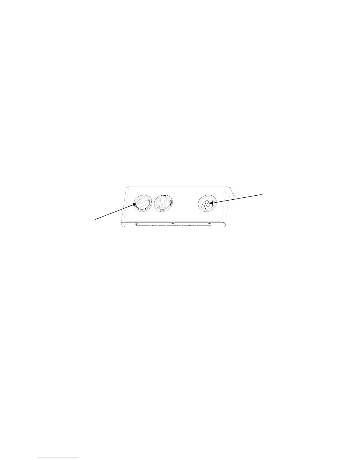
Heater Models: WDFT060/100-VF-IR
WNT060/100-VF-IR
WLT060/100-VF-IR
Igniter button
Temperature
Figure10
1. Turn the thermostat Control button to full position; turn the applianc e gas valve (ON-OFF-PILOT)
button to the “Pilot” position.
2. Push down the appliance gas valve and keep it depressed for several seconds, so that all the air in
the manifolds is clear.
3. Keep the gas valve button depressed and push down t he igniter button several times until the pilot is
lit.
4. Keep the gas valve button depressed for at least 10 seconds, so that the pilot sensor is heated up
enough. Release the gas valve button. If pilot goes out, repeat step 3 and step 4.
5. When the pilot flame is stable, slightly push the gas valve button down and turn to the “ON” position
QUICKLY. Heater will then operate normally. Now you can turn the thermostat control button to the
position as your desired.
To stop the heater shut off the external safety valve in gas inlet line (not part of the heater), then turn the
appliance gas valve to “OFF” position.
17

Heater Models: WDFT250-VF-IR
WNT250-VF-IR
WLT250-VF-IR
Temperature/Pilot
Igniter button
Figure11
1. Turn the appliance combination control valve button to the “Pilot” position.
2. Push down the appliance combination control valve button and keep it depressed for several seconds,
so that all the air in the manifolds are clear.
3. Keep the gas valve button depre ssed and meanwhile push down the igniter button several times until
the pilot is lit.
4. Keep the gas valve button depressed for at least 10 seconds, so that the pilot sensor is heated up
enough. Release the gas valve button. If pilot goes out, repeat step 3 and step 4.
5. When the pilot flame is stable, slightly push the gas valve button down and turn to the “6 o’clock”
position QUICKLY. Heater will then operate normally. Now you can turn the control button to the
position as your desired.
To stop the heater shut off the external safety valve in gas inlet line (not part of the heater), then turn the
appliance gas valve to “OFF” position.
INSPECTING BURNER
Check pilot flame pattern and burner flame pattern often.
PILOT FLAME PATTERN
Figure 12 shows a correct pilot flame pattern.
Figure 12
WARNING: If yellow tipping occurs, your heater could produce increased levels of carbon monoxide.
If burner flame pattern shows yellow tipping, follow instructions at bottom of this page.
Notice: Do not confuse orange flames with yellow tipping. Dirt or other fine particles enter the heater and
burn causing brief patches of orange flame
18

10. CARE AND MAINTENANCE
WARNING: Turn off heater and let cool before servicing
CAUTION: You must keep control areas, burner, and circulating air passageways of the heater clean.
Inspect these areas of heater before each use. Have heater inspected yearly by a qualified service
technician. Heater may need more frequent cleaning due to excessive lint from carpeting, bedding
material, pet hair, etc.
ODS/PILOT AND BURNER
Use a vacuum cleaner, pressurized air, or a small, soft bristled brush to clean.
CLEANING BURNER PILOT AIR INLET HOLE
We recommend that you clean the unit every 2,500 hours of operation
or every three months. We also recommend that you keep the burner
tube and pilot assembly clean and free of dust and dirt. To clean these
parts we recommend using compressed air no greater than 30 PSl.
Your local computer store, hardware store, or home center may carry
compressed air in a can. You can use a vacuum cleaner in the blow
position. If using compressed air in a can, please
follow the directions on the can. If you don’t follow directions
Figure13
on the can, you could damage the pilot assembly.
1. Shut off the unit, including the pilot. Allow the unit to cool for at least thirty minutes.
2. Inspect burner and pilot for dust and dirt.
3. Blow air through the ports/slots and holes in the burner. Also clean the pilot assembly. A yellow tip on
the pilot flame indicates dust and dirt in the pilot assembly. There is a small pilot air inlet hole about two
inches from where the pilot flame comes out of the pilot assembly (see Figure13. With the unit off, lightly
blow air through the air inlet hole. You may blow through a drinking straw if compressed air is not
available.
CABINET
Air Passageways
Use a vacuum cleaner or pressurized air to clean.
Exterior
Use a soft cloth dampened with a mild soap and water mixture.
Wipe the cabinet to remove dust
1) Use a soft cloth dampened with a mild soap and water mixture.
2) Wipe the cabinet to remove dust.
19

11. TROUBLE SHOOTING
WARNING: If you smell gas:
1) Open the window and door immediately.
2) Shut off gas supply.
3) Do not try to light any appliance.
4) Do not touch any electrical switch; do not use any phone in your building.
5) Immediately call your gas supplier from a neighbor’s phone. Follow the gas supplier’s instructions.
6) If you cannot reach your gas supplier, call the fire department.
IMPORTANT: Operating heater where impurities in air exist may create odors. Cleaning supplies, paint,
paint remover, cigarette smoke, cements and glues, new carpet or textiles, etc., create fumes. These
fumes may mix with combustion air and create odors.
WARNING: Only a qualified service technician should service and repair heater.
CAUTION: Never use a wire, needle, or similar object to clean ODS/pilot. This can damage ODS/ pilot
unit. Note: All troubleshooting items are listed in order of operation.
No. PROBLEM POSSIBLE CAUSE REMEDY
When igniter button is pressed in
1
there is no spark at ODS/pilot.
When igniter button is
2
pressed in there is a spark
at ODS/pilot but no ignition.
ODS/pilot lights but flame
3
goes out when control
knob is released.
Burner(s) does not light
4
after ODS/pilot is lit.
Delayed ignition of
5
burner(s).
1. Igniter electrode is positioned
wrong or broken.
2. Igniter electrode is not connected to
igniter cable.
3. Igniter cable is pinched or wet.
4. Broken igniter cable.
5. Bad piezo igniter.
1. Gas supply is turned off or
equipment
shutoff valve is closed.
2. Control knob not fully pressed in
while
pressing igniter button.
3. Air in gas lines when installed.
4. ODS/pilot is clogged.
5. Gas regulator setting is not correct.
6. Control knob not in PILOT position.
7. Depleted gas supply (propane).
1. Control knob is not fully pressed in.
2. Control knob is not pressed in long
enough.
3. Equipment shutoff valve is not
fully open.
4. Thermocouple connection is loose
at control valve.
5. Thermocouple damaged.
6. Control valve damaged.
1. Burner orifice is clogged.
2. Burner orifice diameter is too small.
3. Inlet gas pressure is too low.
1. Manifold pressure is too low.
2. Burner orifice is clogged.
20
1. Replace igniter.
2. Reconnect igniter cable.
3. Free igniter cable if pinched by any
metal or tubing. Keep igniter cable dry.
4. Replace igniter cable.
5. Replace piezo igniter.
1. Turn on gas supply or open equipment
shutoff valve.
2. Fully press in control knob while
pressing igniter button.
3. Continue holding down control knob.
Repeat igniting operation until air is
removed.
4. Clean ODS/pilot (see Care and
Maintenance, page 15) or replace ODS/
pilot assembly.
5. Replace gas regulator.
6. Turn control knob to PILOT position.
7. Contact local propane/LP gas company.
1. Press in control knob fully.
2. After ODS/pilot lights, keep control knob
pressed in 30 seconds.
3. Fully open equipment shutoff valve
4. Hand tighten until snug, and then
tighten 1/4 turn more.
5. Replace thermocouple.
6. Contact customer service.
1. Clean burner orifice (see Care and
Maintenance, page 15) or replace
burner orifice.
2. Contact customer service.
3. Contact local gas supplier.
1. Contact local gas supplier.
2. Clean burner (see Care and
Maintenance, page 15) or replace
burner orifice.

Burner backfiring
6
during combustion.
Yellow flame during
7
burner combustion.
1. Burner orifice is clogged or
damaged.
2. Burner is damaged.
3. Gas regulator is defective.
1. Not enough air.
2. Gas regulator is defective.
3. Inlet gas pressure is too low.
1. Clean burner orifice (see Care and
Maintenance, page 15) or replace.
2. Contact customer service.
3. Replace gas regulator.
1. Check burner for dirt and debris. If
found, clean burner (see Care and
Maintenance, page 15).
2. Replace gas regulator.
3. Contact local gas supplier.
Slight smoke or odor
8
during initial operation.
Heater produces a
9
whistling noise
when burner is lit.
1. Residues from manufacturing
processes.
1. Turning control knob to HI position
when burner is cold.
2. Air in gas line.
3. Air passageways on heater are
blocked.
4. Dirty or partially clogged burner
orifice.
1. Problem will stop after a few hours of
operation.
1. Turn control knob to LO position and let
warm up for a minute.
2. Operate burner until air is removed
from line. Have gas line checked by
local gas supplier.
3. Observe minimum installation
clearances (Figure 4, page 15).
4. Clean burner (see Care and
Maintenance, page15) or replace
burner orifice
Heater produces a
10
clicking/ ticking noise
just after burner is lit
or shut off.
1. Metal is expanding while
heating or contracting while
cooling.
1. This is common with most heaters. if
noise is excessive, contact qualified
service technician.
White powder residue
11
forming within burner box
or on adjacent walls or
furniture.
1. When heated, the vapors from
furniture polish, wax, carpet cleaners,
etc., turn into white powder residue.
1. Turn heater off when using furniture
polish, wax, carpet cleaner, or similar
products.
Heater produces
12
unwanted odors.
Heater shuts off in use
13
(ODS operates).
1. Heater is burning vapors from
paint, hair spray, glues, etc. See
IMPORTANT statement page 16.
2. Gas leak. See Warning Statement
at the top of page16.
3. Low fuel supply.
1. Not enough fresh air is available.
2. Low line pressure.
3. ODS/pilot is partially clogged.
1. Ventilate room. Stop using odor causing
products while heater is running.
2. Locate and correct all leaks (see
Checking Gas Connections, page 11).
3. Refill supply tank (Propane / LP
models).
1. Open window and/or door for
ventilation.
2. Contact local gas supplier.
3. Clean ODS/pilot (see Care and
Maintenance, page15).
1. Open window and/or door for
14
ventilation.
2. Contact local gas supplier.
3. Clean ODS/pilot (see Care and
Maintenance, page 22).
1. Gas leak. See Warning Statement
at top of page 16.
2. Control valve is defective.
1. Locate and correct all leaks (see
“Checking Gas Connections”, page
11).
2. Contact customer service.
Gas odor during
15
combustion.
1. Foreign matter between control
valve and burner.
2. Gas leak. See Warning Statement
at top of page 16.
1. Take apart gas tubing and remove
foreign matter.
2. Locate and correct all leaks (see
“Checking Gas Connections”, page 11).
21

U
0
R
ILL
STRATED PARTS (Models: WDFT
60-VF-I
)
22

PARTS LIST (Model: WDFT060-VF-IR)
Code Description Code Description
1 Grill 22 NG Nozzle
2 Body cover 23 LPG Nozzle
3 Scatter panel 24 Nozzle holder
4 Gas elbow 25 Gas allocator
5 Appliance regulator connecter 2 26 Ceramic plaque
6 Appliance regulator bracket 27 LPG ODS
7 Appliance regulator 28 NG ODS
8 Appliance regulator connecter 1 29 Knob
9 Igniter fixing nut 30 Thermostat seat
10 Igniter seat 31 Right insulation board
11 Igniter 32 Gas pipe nut
12 Rear insulation board 33 Gas valve seat
13 Left insulation board 34 Shell
14 Over-heat cut-off 35 Thermostat
15 Rear cover 36 Copper bush
16 Installation bracket 37 Thermostat connecting nut
17 Fixing racket 38 Gas safety valve
18 Burning chamber 39 Gas selector bracket
19 Air introducing tube 40 Gas selector nut
20 Nozzle holder fixing nut 41 Gas selector
21 Nozzle holder
23

ILL
U
0
)
STRATED PARTS (Model: WDFT1
0-VF-IR
24

PARTS LIST (Model: WDFT100-VF-IR)
Code Description Code Description
1 Grill 22 Nozzle holder
2 Body cover 23 NG Nozzle
3 Scatter panel 24 LPG Nozzle
4 Gas elbow 25 Nozzle holder nut
5 Appliance regulator connecter 2 26 Air introducing tube
6 Appliance regulator bracket 27 Ceramic plaque
7 Appliance regulator 28 LPG ODS
8 Appliance regulator connecter 1 29 NG ODS
9 Shell 30 Right insulation board
10 Igniter fixing nut 31 Knob
11 Igniter seat 32 Gas pipe nut
12 Igniter 33 Thermostat seat
13 Rear insulation board 34 Gas valve seat
14 Left insulation board 35 Thermostat
15 Over-heat cut-off 36 Copper bush
16 Rear cover 37 Thermostat connecting nut
17 Installation bracket 38 Gas safety valve
18 Fixing racket 39 Gas selector bracket
19 Burning chamber 40 Gas selector fixing nut
20 Gas allocator 41 Gas selector
21 Nuzzle holder bracket
25

ILL
U
5
STRATED PARTS (Model: WDFT2
0-VF-IR)
26

PARTS LIST (Model: WDFT250-VF-IR)
Code Description Code Description
1 Grill 21 LPG ODS
2 Body cover 22 NG ODS
3 Scatter panel 23 Right insulation board
4 Shell 24 Combination control valve seat
5 Rear insulation board 25 Gas Valve bracket
6 Left insulation board 26 Combination control valve
7 Over-heat cut-off 27 Gas Connecter
8 Rear cover 28 Gas pipe nut
9 Installation bracket 29 Igniter seat
10 Fixing racket 30 Igniter fixing nut
11 Burning chamber 31 Igniter
12 Nozzle holder bracket 32 Appliance regulator bracket
13 Nozzle holder 33 Appliance regulator connecter 1
14 Nozzle holder fixing nut 34 Appliance regulator
15 NG Nozzle 35 Appliance regulator connecter 2
16 LPG Nozzle 36 Gas elbow
17 Nozzle holder 37 Gas selector fixing nut
18 Air introducing tube 38 Gas selector bracket
19 Gas allocator 39 Gas selector
20 Ceramic plaque
27

ILL
U
6
STRATED PARTS (Models: WNT0
0-VF-IR/WLT060-VF-IR)
28

Part List (Models: WNT060-VF-IR/WLT060-VF-IR)
Code Description Code Description
1 Grill 20 Nozzle holder bracket
2 Body cover 21 LP Nozzle (WLT060-VF-IR)
3 Scatter panel 21 NG Nozzle (WNT060-VF-IR)
4 Gas elbow 22 Nozzle holder
5 Appliance regulator connecter 2 23 Gas allocator
6 Appliance regulator bracket 24 Ceramic plaque
7 NG Appliance regulator
25 NG ODS (WNT060-VF-IR)
(WNT060-VF-IR)
7 LP Appliance regulator
25 LP ODS (WLT060-VF-IR)
(WLT060-VF-IR)
8 Appliance regulator connecter 1 26 Knob
9 Igniter seat 27 Thermostat seat
10 Igniter fixing nut 28 Right insulation board
11 Igniter 29 Gas pipe nut
12 Rear insulation board 30 Gas valve seat
13 Left insulation board 31 Thermostat
14 Rear cover 32 Copper bush
15 Installation bracket 33 Thermostat connecting nut
16 Fixing racket 34 Gas safety valve
17 Burning chamber 35 Shell
18 Air introducing tube
19 Nozzle holder fixing nut
29

ILL
U
0
STRATED PARTS (Models: WNT1
0-VF-IR/WLT100-VF-IR)
30

Part List (Models: WNT100-VF-IR/WLT100-VF-IR)
Code Description Code Description
1 Grill 20 Nozzle holder bracket
2 Body cover 21 Nozzle holder
3 Scatter panel 22 LP Nozzle (WLT100-VF-IR)
4 Gas elbow 22 NG Nozzle (WNT100-VF-IR)
5 Appliance regulator connecter 2 23 Nozzle holder fixing nut
6 Appliance regulator bracket 24 Air introducing tube
7
7
NG Appliance regulator
(WNT100-VF-IR)
LP Appliance regulator
(WLT100-VF-IR)
25 Ceramic plaque
26 NG ODS (WNT100-VF-IR)
8 Appliance regulator connecter 1 26 LP ODS (WLT100-VF-IR)
9 Shell 27 Right insulation board
10 Igniter fixing nut 28 Knob
11 Igniter seat 29 Gas pipe nut
12 Igniter 30 Thermostat seat
13 Rear insulation board 31 Gas valve seat
14 Left insulation board 32 Thermostat
15 Rear cover 33 Copper bush
16 Installation bracket 34 Thermostat connecting nut
17 Fixing racket 35 Gas safety valve
18 Burning chamber
19 Gas allocator
31

ILL
U
5
STRATED PARTS (Models: WNT2
0-VF-IR/WLT250-VF-IR)
32

Part List (Models: WNT250-VF-IR/WLT250-VF-IR)
Code Description Code Description
1 Grill 18 Ceramic plaque
2 Body Cover 19 NG ODS (WNT260-VF-IR)
3 Scatter panel 19 LP ODS (WLT260-VF-IR)
4 Shell 20 Right insulation board
5 Rear insulation board 21 Combination control valve seat
6 Left insulation board 22 Valve bracket
7 Rear cover 23 Combination control valve
8 Installation bracket 24 Connecter
9 Fixing racket 25 Gas pipe nut
10 Burning chamber 26 Igniter seat
11 Nozzle holder bracket seat 27 Igniter fixing nut
12 Nozzle holder bracket 28 Igniter
13 Nozzle holder fixing nut 29 Appliance regulator bracket
14 LP Nozzle (WLT250-VF-IR) 30 Appliance regulator connecter 1
14 NG Nozzle (WNT250-VF-IR) 31 Appliance regulator
15 Nozzle holder 32 Appliance regulator connecter 2
16 Air introducing tube 33 Gas elbow
17 Gas allocator
33

Questions about installation, operation, or troubleshooting should be directed to your
installer. If you have additional support questions please call our customer service at
1-877-670-8428 or visit www.thermablaster.com
Annual Service Schedule
Service Performed Service Date
Please send in the form below to our office listed below or register online at www.thermablaster.com
Reecon North America
Attn: Thermablaster
1090 Freeport Road
nd
2
Floor
Pittsburgh, PA 15238
------------------------------------------------------------------------------------------------------------------------------Contact Information Product Information
Name: Model:
Phone: Serial Number:
Email: Date of Purchase:
Address:
Retailer Purchased From:
City: Installer Company:
State: Installer Phone:
Zip Code: Installer Zip Code:
**All information above is required in order for our company to honor the warranty.**
Comments:
34
 Loading...