

Page 1
1-4
FUNCTION
INSTALLATION
Models: THERACLEAR 255
(Clamp down multiport valve in 50mm)
THIS FILTER OPERATES UNDER HIGH PRESSURE. WHEN ANY PART OF THE CIRCULATING
SYSTEM (e.g., CLAMP, PUMP, FILTER, VALVES, ETC.) IS SERVICED, AIR CAN ENTER THE
SYSTEM AND BECOME PRESSURIZED . PRESSURIZED AIR CAN CAUSE THE LID OR VALVE TO
BE BLOWN OFF WHICH CAN RESULT IN SEVERE INJURY, DEATH, OR PROPERTY DAMAGE
TURN PUMP OFF BEFORE CHANGING VALVE POSITION.
WARNING
!
!
4-4
TO PREVENT DAMAGE TO THE PUMP AND FOR PROPER OPERATION OF THE SYSTEM,
CLEAN PUMP STRAINER AND SKIMMER BASKETS REGULARLY.
!
Valve Position Function
DO NOT UNSCREW SCREWS OF FLANGE CLAMP WHILE PUMP IS RUNNING.
!
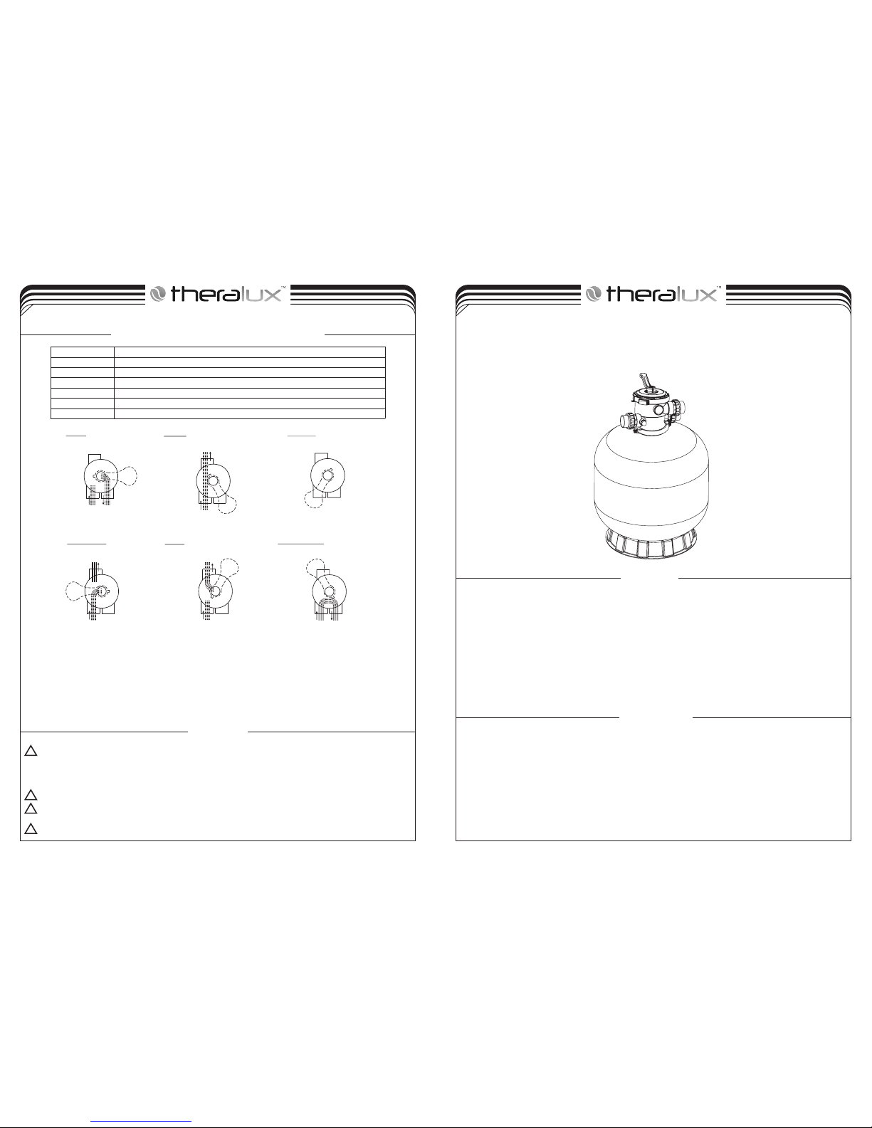
FUNCTIONS OF VALVE POSITIONS
WASTE
FILTER
BACKWASH
RINSE
WASTE
RECIRCULATE
CLOSED
WASTE WASTE
WASTE WASTE WASTE
IN FLOW
OUT FLOW
IN FLOW
OUT FLOW
IN FLOW
OUT FLOW
IN FLOW
OUT FLOW
IN FLOW
OUT FLOW
IN FLOW
OUT FLOW
GENERAL
TO ASSEMBLE:
The filter uses special filter sand to remove dirt particles from pool water. The filter sand is loaded into the filter tank and functions as
a permanent dirt removing media. When the control valve is in the FILTER position, the pool water which contains suspended dirt
particles, is pumped through your piping system and is automatically directed by the patented filter control valve to the top of the filter
tank. As the pool water is pumped through the filter, dirt particles are trapped by the sand bed, and filtered out. The cleaned pool water is
returned from the bottom of the filter tank, through the control valve and back to the pool through the piping system. This entire sequence
is continuous and automatic. It provides for total recirculation of pool water through your filter and piping system.
After a period of time, the accumulated dirt in the filter causes a resistance to flow, and the flow diminishes. This means it is time to
clean your filter. With the control valve in the BACKWASH position, the water flow is automatically reversed through the filter so that it
is directed to the bottom of the tank, up through the sand, flushing the previously trapped dirt and debris out the waste line. Once the filter
is back-washed of dirt, set control valve to RINSE position and run pump for about 1/2 to 1 minute, and then set the control valve in the
FILTER position, to resume normal filtering.
NOTE: Turn pump off before changing valve position.
Only simple tools (screwdriver and wrenches), plus pipe sealant for plastic adapters, are required to install and
service the filter.
1. The filter should be placed on a level concrete slab, very firm ground, or equivalent. The filter should be placed
2. Loading the sand media. Filter sand media is loaded through the top opening of the filter.
a. Loosen the flange clamp and remove filter control valve (if previously installed).
b. Cap internal pipe with plastic cap to prevent sand from entering it.
c. We recommend filling the tank approximately 1/2 way with water to provide a cushion effect when the filter
d. Carefully pour in correct amount and grade of filter sand. (Be sure center pipe remains centered in opening.)
internal pipe.
in the right position so that the piping connections, control valve are convenient and accessible for operation and service.
sand is poured in. This helps protect the under-drain laterals from excessive shock.
Sand surface should be leveled and should come to about the middle of the filter tank. Remove plastic cap from
SERVICING VALVE( Stop pump,close gate valve in suction&discharge before proceeding):
a. Set handle in filter position. b. Remove cover screws. c. Lift cover and key assembly out.
1. Place valve key so that wedge opening is at TOP port (handle in Filter psn.). Flat edge of cover screw lug should align with
flat edge of body screw lug.
2. Position cover o’ring.
3. Secure assembly to body with cover screws. Tighten cover screws evenly and alternately. Do not over-tighten.
FILTER
BACKWASH
RINSE
WASTE
RECIRCULATE
CLOSED
Normal Filtration and Vacuuming
Cleaning Filter by reversing the flow
Used after backwash to flush dirt from valve
By-passes filter, used for vacuuming to waste or lowering water level
By-passes filter for circulating water to pool
Shuts off all flow to filter or pool
TLFI13070818
Page 2
11
12
13
1
2
3
4
5
6
7
8
9
10
2-4
3. Assemble filter control valve into the filter tank.
a. Insert filter control valve (with o'ring in place) into the tank neck, taking care that the center pipe slips into the hole
b. Place two plastic clamps around valve flange and tank flange and tighten just enough so that the valve may be
d. Connect pump to control valve opening marked PUMP. After connections are made, tighten valve flange clamps with
plumbing connections, suction lines to pump, waste, etc.
5. Make electrical connections to pump per pump instructions.
6. To prevent water leakage, make sure all pipe connections are tight.
4. Make return to pool pipe connection to control valve opening marked RETURN and complete other necessary
MAIN DIMENSION
in the bottom of the valve.
rotated on tank for final positioning.
c. Carefully screw pressure gauge (with in place) into tapped hole in valve body. Do not over-tighten.o'ring
screwdriver, tapping around clamp with screwdriver handle to help seat valve flange clamp.
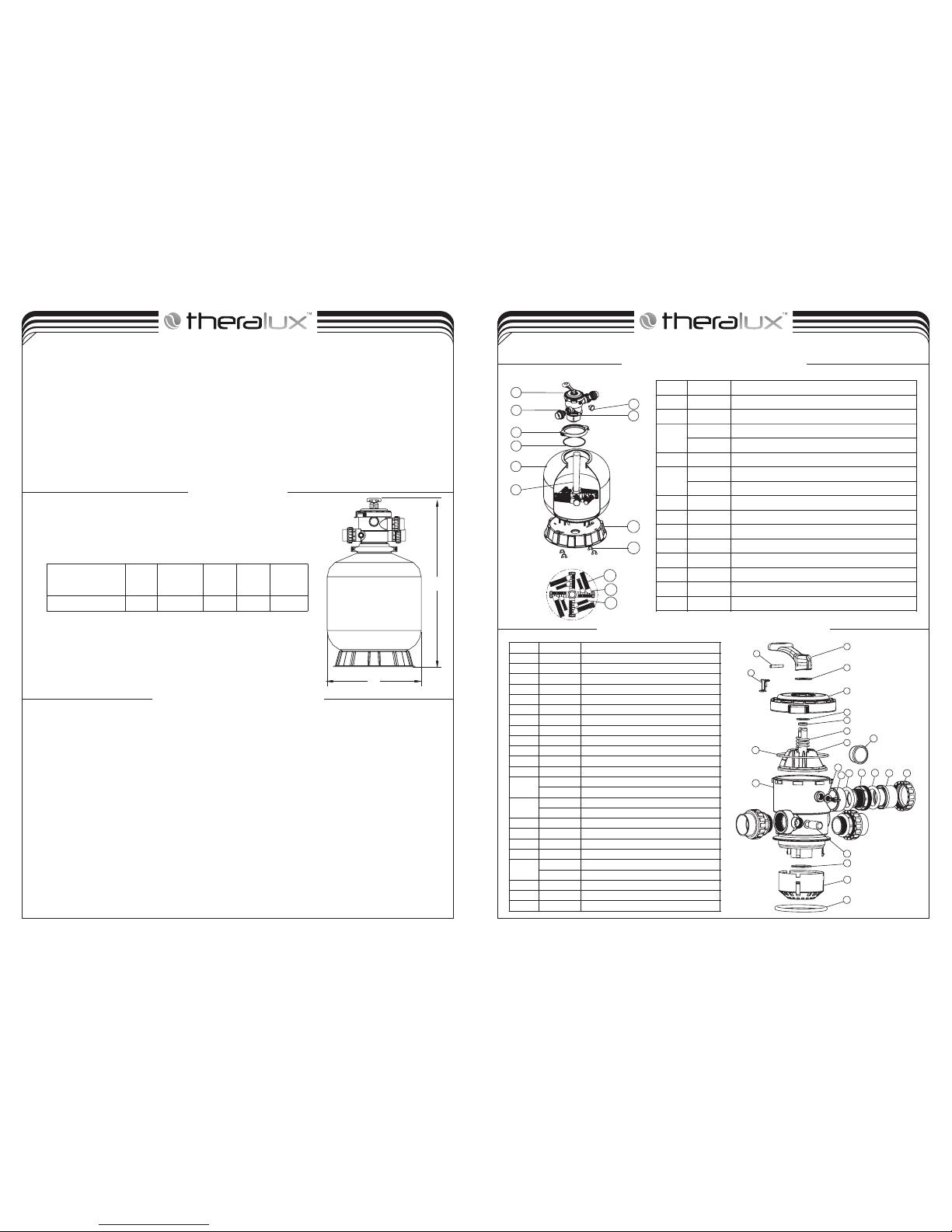
REPLACEMENT PARTS OF FILTER
3-4
1. Make sure the correct amount of filter media sand is located in the tank and all connections have been connected and secured.
2. Depress control valve handle and rotate to BACKWASH position. (To prevent damage to control valve seal, always depress handle
before turning.)
3. Prime and start pump according to pump instructions (be sure all suction and return lines are open), allowing the filter tank to fill with
water. Once water is flowing out of the waste line, run the pump for at least 1 minute. The initial back-washing of the filter is
recommended to remove any impurities or fine sand particles in the sand media.
4. Turn pump off and set valve to RINSE position. Start pump and operate until water in sight glass is clear, about 1/2 to 1 minute. Turn
pump off and set valve to FILTER position and restart pump. The filter is now operating in the normal filter mode, filtering dirt particles
from the pool water.
5. Adjust pool suction and return valves to achieve desired flow. Check system and filter for water leaks and tighten connections, bolts, nuts,
as required.
6. Note the initial pressure gauge reading when the filter is clean. (It will vary from pool to pool depending upon the pump and general piping
system.) As the filter removes dirt and impurities from the pool water, the accumulation of dirt in the filter will cause the pressure to rise
and diminish the water flow. When the pressure gauge reading is 1.5 bar, higher than the initial "clean" pressure you noted, it is time to
backwash the filter (see BACKWASH under filter and control valve functions).
NOTE: During initial clean-up of the pool water it may be necessary to backwash frequently due to the unusually
INSTALL/START-UP OF FILTER
heavy initial dirt load in the water.
B
A
A
B
Model
High Diameter
mm
mm
DIMENSION TABLE
950
THERACLEAR 255
635
inch
Valve Port
Size
Sand
kg
145
2.0"
REPLACEMENT PARTS OF MULTIPORT VALVE
1
3
2
4
5
6
7
8
9
10
11
14
15
16
15
17
18
19
20
21
22
13
12
Key N o.
Par t No.
Pro duct De scrip tion
1
882 81506
MPV 08 6-Wa y 2.0" C lamp Typ e Multi port Valv e
2
892 80103
2.0 "Unio n Set(3 P ieces )With O -Ring f or MPV0 8 Valve
3
060 11029
Oil P ressu re Gaug e With O- rin g (40ps i)
0111104 8
Con necto r for Pre ssure G auge/ Sto pper
4
892 80104
Sig ht glas s with O- Rin g
5
890 10119
M6* 50 Sc rews Wi th Nut
012 71010
Cla mp Lock
6
020 11134
O-R ing for F ilter N eck
7
890 10110
Fil ter tan k8890 10118
Sta ndpip e with hu b
9
0111106 2
Fil ter Bas e1001181 052
Fas tener f or Filt er Base
11
01172 010
Lat erals ( 185 mm)
12
01172 007
Lat erals b racke t
13
890 12516
Lat erals ( 115mm )
Key N o.
Par t No.
Pro duct De scrip tion
1
010 13003
Han dle(B ig)
2
030 18008
Pin f or Hand le
3
01181 027
Wash er for Ha ndle
4
01181 028
Def end Loc k
5
010 20009
2.0 " Lid601181 002
Wash er for Ha ndle
7
020 11022
O-R ing for 2 .0" Val ve Roto r
8
030 14014
Spr ing9010 20002
2.0 " Valve Ro tor wit h O-Ri ng
10
020 10003
O-R ing for L id
11
010 20010
2.0 " Body120111104 8
Con necto r for pre ssure g auge/ sto pper
13
0111101 7
O-R ing for D rain Pl ug
020 20014
Dra in Plug14060 11029
Oil P ressu re Gaug e With O- Ring( 40psi )
060 21013
Pla stic Pr essur e Gauge W ith O-R ing(4 0psi)
15
020 20016
1.5 "Uni on Nut( Bla ck)
16
010 13031
2.0 "Con necto r (bla ck)
17
011711 54
2.0 "Uni on (A/ E)
18
010 13032
2.0 "Uni on Nut( Bla ck)
19
020 11008
O-R ing for S ight Gl ass
010 41004
Sig ht Glas s
20
020 11005
O-R ing for D iffus er
21
01100 001
2.0 " Diffu ser
22
020 11134
O-R ing
105
Glass
Media
kg
Theraclear Glass Filter Media recommended rate:
5 bags x Fine Grade
2 bags x Course Grade (added to tank first)
 Loading...