

Page 1
U s e r M a n u a l
U s e r M a n u a l
I n s t a l l a t i o n
I n s t a l l a t i o n
M a n u a l
M a n u a l
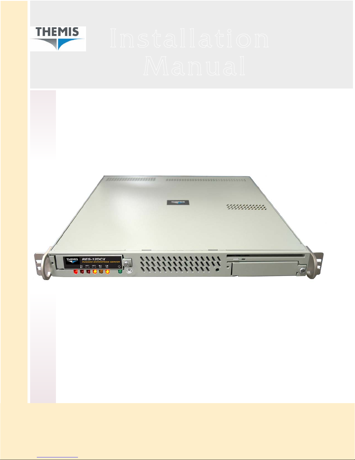
RES-12DCX
RES-12DCX
Tw o I ntel D ual -C or e/ Q ua d- Co re 64 -b it Xe on C PUs / 1 RU Se rv er
PC I- Exp re ss & PC I- X Slo ts / G i ga bi t Eth er ne t / S er ia l ATA (SATA )
Se ri al- At ta ch e d SC SI (S AS ) / R AI D / IDE -E ID E / F lo pp y / V GA / U SB
Page 2
2 I n t e l D u a l -C o re / Qu a d- C or e 6 4 -b i t X eo n C P Us / 1 RU Se r ve r
2 I n t e l D u a l -C o re / Qu a d- C or e 6 4 -b i t X eo n C P Us / 1 RU Se r ve r
2 I n t e l D u a l -C o re / Qu a d- C or e 6 4 -b i t X eo n C P Us / 1 RU Se r ve r
2 I n t e l D u a l -C o re / Qu a d- C or e 6 4 -b i t X eo n C P Us / 1 RU Se r ve r
2 I n t e l D u a l -C o re / Qu a d- C or e 6 4 -b i t X eo n C P Us / 1 RU Se r ve r
R E S - 1 2 D C X
R E S - 1 2 D C X
R E S - 1 2 D C X
R E S - 1 2 D C X
R E S - 1 2 D C X
R E S - 1 2 D C X
R E S - 1 2 D C X
R E S - 1 2 D C X
R E S - 1 2 D C X
R E S - 1 2 D C X
Page 3

RES-12DCX Installation Manual
Version 1.1— March 2008
Themis Computer—Americas and Pacific Rim
47200 Bayside Parkway
Fremont, CA 94538
Phone (510) 252-0870
Fax (510) 490-5529
World Wide Web http://www.themis.com
Themis Computer—Rest of World
5 Rue Irene Joliot-Curie
38320 Eybens, France
Phone +33 476 14 77 80
Fax +33 476 14 77 89
Page 4

Copyright © 2008 Themis Computer, Inc.
ALL RIGHTS RESERVED. No part of this publication may be reproduced in any form, by
photocopy, microfilm, retrieval system, or by any other means now known or hereafter invented without
the prior written permission of Themis Computer.
The information in this publication has been carefully checked and is believed to be accurate. However,
Themis Computer assumes no responsibility for inaccuracies. Themis Computer retains the right to
make changes to this publication at any time without prior notice. Themis Computer does not assume
any liability arising from the application or use of this publicat ion or the product(s) described herein.
RESTRICTED RIGHTS LEGEND: Use, duplication, or disclosure by the United States Government
is subject to the restrictions set forth in DFARS 252.227-7013 (c)(1)(ii) and FAR 52.227-19.
TRADEMARKS and SERVICEMARKS
®
Themis
Intel
Xeon
ATI
Intersil
Red Hat
Linux
All other trademarks, servicemarks, or registered trademarks used in this publication are the property of
their respective owners.
is a registered trademark of Themis Computer, Inc.
®
is a registered trademark of Intel Corporation.
™
is a trademark of Intel Corporation.
™
is a trademark of Advanced Micro Devices, Inc. (AMD)
®
is a registered trademark of Intersil Americas Inc.
®
is a registered trademark of Red Hat, Inc.
®
is a registered trademark of Linus Torvalds.
North America, South America, and Pacific Rim
RES-12DCX Installation Manual, Version 1.1
March 2008
Part Number: 115298-024
Themis Customer Support
Telephone: 510-252-0870
Fax: 510-490-5529
E-mail: [email protected]
Web Site: http://www.themis.com
Page 5

RES-12DCX Installation Manual
Version Revision History
Ve rsion 1. 1......................................................................................... March 2008
• Modified Table 1-1, page 1-4, to include DC power supplies.
• Modified
• Added a section (German) on Safety Instructions before the Table of Contents.
• Assorted minor edits and changes throughout the manual.
Table 1-2, page 1-11, to define Overheat/Fan Fail LED function.
Ve rsion 1. 0..................................................................................... February 2008
Themis Computer
iii
Page 6
RES-12DCX Installation Manual
Safety Instructions
To maximize user safety and ensure correct device operation, all instructions contained in this section should be read carefully.
Caution: It is important that the user observe all warnings and instructions that are
on the device and contained in this manual.
• The device must be used in accordance with the instructions for use.
• Electrical installations in the room must correspond to the requirements of
respective regulations.
• Take care that there are no cables, particularly mains cables, in areas where
persons can trip over them.
• Do not use a mains connection in sockets shared by a number of other power
consumers. Do not use an extension cable.
• Only use the mains cable supplied.
• The unit is completely disconnected from the power source only when the
power cord is disconnected from the power source. Therefore the power cord
and its connectors must always remain easily accessible.
• Do not set up the device in the proximity of heat sources or in a damp location.
Make sure the device has adequate ventilation.
• All plugs on the connection cables must be screwed or locked to the chassis
housing.
• The device is designed to be used in horizontal position only.
• The device is no longer safe to operate when
— the device has visible damage or
— the device no longer functions.
• In these cases, the device must be shut down and secured against unintentional
operation.
• Repairs may only be carried out by a person authorized by Themis Computer.
iv
Themis Computer
Page 7

• The device may only be opened for the installation and removal of extension
(PCI) cards, memory modules, hard-disk drives, fan housings, power supplies
(RES-22 and RES-32 systems only), and the lithium battery—all in accordance
with the instructions given in this manual.
• If extensions are made to the device, the legal stipulations and the device specifications must be observed.
• The device must be switched off when removing the top cover; for example,
before installing extension (PCI) cards.
Operation of Laser Source Devices
DVD/CD-ROM drives contain laser light-emitting diodes (classified in accordance
with IEC 825-1:1993: LASER CLASS 1) and, therefore, must not be opened.
RES-12DCX Installation Manual
If the enclosure of such a drive is opened, invisible laser radiation is emitted. Do
not allow yourself to be exposed to this radiation.
The laser system meets the code of Federal Regulations 21 CFR,1040 for the USA
and Canadian Radiation Emitting Devices Act, REDR C 1370.
Electrostatic Discharge (ESD)
A sudden discharge of electrostatic electricity can destroy static-sensitive devices
or micro-circuitry. Proper packaging and grounding techniques are necessary precautions to prevent damage. Always take the following precautions:
1. Transport boards in static-safe containers such as boxes or bags.
2. Keep electrostatic-sensitive parts in their containers until they arrive at static-
free stations.
3. Always be properly grounded when touching a sensitive board, component, or
assembly.
4. Store electrostatic-sensitive boards in protective packaging or on conductive
foam.
Themis Computer
v
Page 8
RES-12DCX Installation Manual
Grounding Methods
Guard against electrostatic damage at workstations by following these steps:
1. Cover workstations with approved anti-static material. Provide a wrist strap
connected to a work surface and properly grounded tools and equipment.
2. Use anti-static mats, heel straps, or air ionizers to give added protection.
3. Handle electrostatic-sensitive components, boards, and assemblies by the case
or the PCB edge.
4. Avoid contact with pins, leads, or circuitry.
5. Turn off power and input signals before inserting and removing connectors or
test equipment.
6. Keep the work area free of non-conductive materials such as ordinary plastic as-
sembly aids and Styrofoam.
7. Use field service tools, such as cutters, screwdrivers, and vacuums that are con-
ductive.
8. Always place drives and boards PCB-assembly-side down on the foam.
Instructions for the Lithium Battery
RES systems are equipped with a lithium battery installed on the motherboard. To
replace this battery, please observe the instructions that are described in this manual.
Warning: There is a danger of explosion when the wrong type of battery is used as
a replacement.
vi
Themis Computer
Page 9

RES-12DCX Betriebshandbuch
Auszug aus RES-12DCX Betriebshandbuch:
Sicherheitshinweise
Hersteller: Themis Computer
47200 Bayside Parkway
Fremont, CA 94538, U.S.A.
Tel.-Nr. 001-510-252-0870
Fax-Nr. 001-510-490-5529
Allgemeine Bezeichnung: Rechner-Arbeitsplatz
Handelsname/Typenbezeichnung: RES-12DCX (Rugged Enterprise Server)
Typ-Identikatoren: RES-12DCX Server, IR
RES-12DCX Server, RC/CC
Deutsche Version Nr. 01/2008 vom 20.03.2008
Themis Computer
vii
Page 10
RES-12DCX Betriebshandbuch
Sicherheitshinweise
Lesen Sie im Interesse Ihrer eigenen Sicherheit und des bestimmungsgemäßen
Gebrauchs diesen Abschnitt sorgfältig durch.
Achtung: Die Wa rnungen und Hinweise auf dem Gerät und in dieser Anleitung
sind unbedingt zu beachten.
• Das Gerät darf nur entsprechend der Gebrauchsanweisung verwendet wer-
den.
• Die elektrische Installation im Raum muss den geltenden V orschrif ten ent spre-
chen.
• Kabel (insbesondere Netzkabel) dürfen nicht in Bereichen verlegt werden, in
denen Personen darüber stolpern können.
• Für den Netzanschluss dürfen keine Verteilerdosen benutzt werden, an die
noch andere Stromverbraucher angeschlossen sind. Verwenden Sie keine
Verlängerungskabel.
• Verwenden Sie nur das mitgelieferte Netzkabel.
• Die vollständige Trennung de s Gerätes von der Netzsp a nnung ist nur gewä hr-
leistet, wenn das Netzkabel vom Netz getrennt wird. Aus diesem Grund muss
das Netzkabel samt seinen Anschlüssen jederzeit leicht zugänglich sein.
• Das Gerät darf nicht in der Nähe von Wärmequellen oder an einem feuchten
Ort aufgestellt werden. Achten Sie auf eine ausreichende Belüftung des
Gerätes.
• Alle Stecker an den Verbindungskabeln müssen am Gehäuse festgeschraubt
oder festgeklemmt sein.
• Das Gerät darf nur in horizontaler Lage betrieben werden.
• Die Betriebssicherheit des Gerätes ist nicht mehr gewährleistet, wenn
— das Gerät sichtbare Beschädigungen aufweist oder
— das Gerät nicht mehr funktioniert.
• In diesen Fällen muss das Gerät ausgeschaltet und gegen unbeabsichtigte
Inbetriebnahme gesichert werden.
viii
Themis Computer
Page 11

• Reparaturen dürfen nur von Beauftragten der Firma Themis Computer durch-
geführt werden.
• Das Öffnen des Gerätes ist nur zulässig für den Ein- und Ausbau von Erweit-
erungskarten (PCI), Speichermodulen, Festplatten, Lüftergehäusen, Netzteilen (nur RES-22- und RES-32-Systeme) und der Lithiumbatterie –
entsprechend den Anweisungen in dieser Anleitung.
• Bei einer Erweiterung des Gerätes sind die gesetzlichen Bestimmungen und
die Gerätespezifikationen zu beachten.
• Vor Abnehmen des Deckels, z.B. für den Einbau von Erweiterungskarten
(PCI), erst das Gerät ausschalten.
Betrieb von Lasergeräten
DVD/CD-ROM-Laufwerke enthalten Laserdioden (Klassifizierung gemäß IEC
825-1:1993: LASERKLASSE 1) und dürfen deshalb nicht geöffnet werden.
RES-12DCX Betriebshandbuch
Beim Öffnen des Laufwerkgehäuses tritt unsichtbare Laserstrahlung aus. Setzen
Sie sich dieser Strahlung keinesfalls aus.
Das Lasersystem erfüllt die Anforderungen des Code of Federal Regulations 21
CFR,1040 (für die USA) und des Canadian Radiation Emitting Devices Act,
REDR C 1370 (für Kanada).
Elektrostatische Entladung (ESD)
Eine plötzliche elektrostatische Entladung kann empfindliche Geräte oder Mikroschaltungen zerstören. Dem ist durch ordnungsgemäße Verpackung und Erdung
unbedingt vorzubeugen. Die folgenden Vorsichtsmaßnahmen sind jederzeit zu
beachten:
1. Transportieren Sie Platinen in elektrostatisch sicheren Behältern oder Taschen.
2. Belassen Sie elektrostatisch empfindliche Bauteile bis zum Eintreffen an einem
antistatischen Ort in ihrem Behälter.
3. Achten Sie beim Berühren empfindlicher Platinen, Bauteile oder Baugruppen
stets auf eine gute Eigenerdung.
4. Lagern Sie elektrostatisch empfindliche Platinen in Schutzverpackungen oder
auf leitfähigem Schaumstoff.
Themis Computer
ix
Page 12
RES-12DCX Betriebshandbuch
Erdungsmethoden
Die folgenden Maßnahmen schützen vor elektrostatischen Schäden am Arbeitsplatz:
1. Legen Sie am Arbeitsplatz geeignete Antistatikmatten aus. Tragen Sie ein Er-
dungsarmband, das mit dem Arbeitsplatz verbunden ist, und verwenden Sie nur
ausreichend geerdete Arbeitsmittel.
2. Verwenden Sie als zusätzlichen Schutz geeignete Antistatikfußmatten, Fersen-
bänder oder Luftionisatoren.
3. Fassen Sie elektrostatisch empfindliche Bauteile, Platinen und Baugruppen nur
am Gehäuse oder am Rand an.
4. Vermeiden Sie den Kontakt mit Stiften, Leitungen und Leiterbahnen.
5. Schalten Sie vor dem Anschließen und T rennen von Steckverbindern oder Prüf-
geräten alle Spannungs- und Signalquellen aus.
6. Verwenden Sie am Arbeitsplatz keine nichtleitenden Materialien, wie
gewöhnliche Kunststoffmontagehilfen oder Styropor.
7. Benutzen Sie leitende Werkzeuge (z.B. Messer, Schraubendreher und Staub-
sauger).
8. Legen Sie Laufwerke und Platinen immer mit der Bauteilseite nach unten auf
die Schaumstoffunterlage.
Hinweise zur Lithiumbatterie
Auf dem Motherboard von RES-Systemen befindet sich eine Lithiumbatterie.
Beim Wechseln dieser Batterie sind die entsprechenden Hinweise in dieser Anleitung zu beachten.
Vorsicht: Beim Einbau einer Ersatzbatterie des falschen Typs besteht Explosionsgefahr.
x
Themis Computer
Page 13

Table of Contents
Safety Instructions ................................................................................................................ iv
Sicherheitshinweise ............................................................................................................. viii
Preface ................................................................................................................................xxiii
1. Overview and Specifications ........................................................................................ 1-1
1.1 Overview ................................................................................................................ 1-1
1.1.1 Special Features ......................................................................................... 1-7
1.1.1.1 Recovery from AC Power Loss .................................................. 1-7
1.1.1.2 Voltage Monitors ........................................................................ 1-7
1.1.1.3 Fan Status Monitor ...................................................................... 1-7
1.1.1.4 Environmental Temperature Control ..........................................1-7
1.1.1.5 CPU Overheat LED and Control ................................................ 1-8
1.1.1.6 System Resource Alert (optional) ............................................... 1-8
1.1.1.7 IPMI Module Support ................................................................. 1-8
1.1.1.8 CPU Fan Auto-Off in Sleep (Doze) Mode ................................. 1-8
1.2 Chipset Overview ................................................................................................ 1-12
1.3 Specifications ....................................................................................................... 1-15
Themis Computer
1.1.2 ACPI Features ............................................................................................ 1-8
1.1.2.1 Suspend-State Indicator .............................................................. 1-9
1.1.2.2 Main Switch Override ................................................................. 1-9
1.1.2.3 External Modem Ring-On .......................................................... 1-9
1.1.2.4 Wake-On-LAN (WOL) ............................................................... 1-9
1.1.3 System LEDs ........................................................................................... 1-10
1.2.1 The Intel 5000P Memory Controller Hub (MCH) ................................... 1-12
1.2.2 The Intel 6321 ESB I/O Controller Hub (ICH) ....................................... 1-13
1.2.3 The Intel 6700 PCI-X 64-bit Hub (PXH-V) ............................................ 1-13
1.2.4 Super I/O Controller ................................................................................ 1-13
1.3.1 General ..................................................................................................... 1-15
1.3.2 Electrical .................................................................................................. 1-16
1.3.2.1 System Power ........................................................................... 1-16
1.3.2.2 Output Voltage .......................................................................... 1-16
xi
Page 14

RES-12DCX Installation Manual
1.3.3 Environmental .......................................................................................... 1-17
1.3.3.1 Shock ........................................................................................ 1-17
1.3.3.2 Electrostatic Discharge ............................................................. 1-17
1.3.3.3 Noise Level ...............................................................................1-17
1.4 Packaging and Shipping ....................................................................................... 1-18
1.4.1 Rack-Mount Slides (Optional) ................................................................. 1-18
2. Installation and Operation ........................................................................................... 2-1
2.1 Installation Procedures ........................................................................................... 2-1
2.1.1 Remove Protective Top Cover ................................................................... 2-1
2.1.2 Memory Modules ....................................................................................... 2-3
2.1.2.1 Installation ..................................................................................2-4
2.1.3 SATA-II Hard-Disk Drive .........................................................................2-6
2.1.3.1 Disk-Drive Removal ................................................................... 2-6
2.1.3.2 Disk-Drive Installation ............................................................... 2-7
2.1.4 PCI Cards ................................................................................................... 2-8
2.1.4.1 Installation ................................................................................2-11
2.1.5 Removable 38-mm Fan Housing ............................................................. 2-12
2.1.5.1 Removing the 38-mm Fan Housing .......................................... 2-12
2.1.5.2 Installing a 38-mm Fan Housing .............................................. 2-13
2.1.6 Lithium Battery ........................................................................................ 2-14
2.1.6.1 Removing the Lithium Battery ................................................. 2-14
2.1.6.2 Installing a Lithium Battery ...................................................... 2-14
2.2 Rack Mounts ........................................................................................................2-15
2.2.1 Mounting Brackets ................................................................................... 2-15
2.2.2 Rack-Mount Slides (Optional) ................................................................. 2-15
2.3 Operation ............................................................................................................. 2-16
2.3.1 Plugging in the AC Power Cord .............................................................. 2-16
2.3.2 Turning the System On ............................................................................2-16
2.3.3 Getting Started ......................................................................................... 2-17
2.3.3.1 Configuration ............................................................................ 2-17
2.3.3.2 Linux Installation ...................................................................... 2-17
2.3.4 Turning the System Off ........................................................................... 2-17
xii
Themis Computer
Page 15

Table of Contents
Appendix A. Connector Pinouts ...................................................................................... A-1
A.1 PS/2 Keyboard and Mouse ................................................................................... A-1
A.2 USB Port ............................................................................................................... A-2
A.3 Serial Port ............................................................................................................. A-3
A.4 Gigabit Ethernet LAN Port ................................................................................... A-4
A.5 VGA Display Port ................................................................................................. A-5
A.6 SAS Port ............................................................................................................... A-6
Appendix B. Rack-Mount Slide Installation ...................................................................B-1
Appendix C. BIOS Setup Utility ......................................................................................C-1
C.1 Introduction ............................................................................................................C-1
C.1.1 System BIOS ..............................................................................................C-1
C.1.2 How To Change the Configuration Data ...................................................C-2
C.1.3 Starting the Setup Utility ...........................................................................C-2
C.2 Running Setup .......................................................................................................C-2
C.3 Main BIOS Setup ...................................................................................................C-3
C.3.1 Main Setup Features ..................................................................................C-4
C.3.1.1 System Time ...............................................................................C-4
C.3.1.2 System Date ................................................................................C-4
C.3.1.3 BIOS Date ...................................................................................C-4
C.3.1.4 Legacy Diskette A ......................................................................C-4
C.3.1.5 IDE Channel 0 Master/Slave, IDE Channel 1 Master/Slave,
SATA Port 2, and SATA Port 3 .................................................C-4
C.3.1.6 Parallel ATA ...............................................................................C-5
C.3.1.7 Serial ATA ..................................................................................C-5
C.3.1.8 Native Mode Operation ..............................................................C-5
C.3.1.9 SATA Controller Mode ..............................................................C-5
C.3.1.10 System Memory ..........................................................................C-6
C.3.1.11 Extended Memory ....................................................................... C-6
C.4 Advanced Setup .....................................................................................................C-7
C.4.1 Boot Features .............................................................................................C-7
C.4.1.1 Quick Boot Mode ........................................................................C-7
C.4.1.2 Quiet Boot Mode ........................................................................C-8
C.4.1.3 POST Errors ................................................................................C-8
C.4.1.4 ACPI Mode .................................................................................C-8
Themis Computer
xiii
Page 16

RES-12DCX Installation Manual
C.4.1.5 Power Button Behavior ...............................................................C-8
C.4.1.6 Resume On Modem Ring ...........................................................C-8
C.4.1.7 Power Loss Control ....................................................................C-8
C.4.1.8 Watch Dog ..................................................................................C-8
C.4.1.9 Summary Screen .........................................................................C-8
C.4.2 Memory Cache ...........................................................................................C-9
C.4.2.1 Cache System BIOS Area ...........................................................C-9
C.4.2.2 Cache Video BIOS Area .............................................................C-9
C.4.2.3 Cache Base 0-512K ....................................................................C-9
C.4.2.4 Cache Base 512K-640K ..............................................................C-9
C.4.2.5 Cache Extended Memory ..........................................................C-10
C.4.2.6 Discrete MTRR Allocation .......................................................C-10
C.4.3 PCI Configuration ....................................................................................C-10
C.4.3.1 Onboard GLAN1/Onboard GLAN2 (Gigabit-LAN)
C.4.3.2 Onboard SCSI OPROM Configure ...........................................C-10
C.4.3.3 PCI Parity Error Forwarding .....................................................C-11
C.4.3.4 Reset Configuration Data ..........................................................C-11
C.4.3.5 Frequency for PCI-X #7, MASS
C.4.3.6 Slot#6 PCI-X 133MHz, Slot E1 x8, Slot E2 x4
OPROM Configure ...................................................................C-10
(Mass Data Storage)/ZCR (Zero Channel RAID) ....................C-11
and Slot E3 x8 ...........................................................................C-11
xiv
C.4.4 Advanced Chipset Control .......................................................................C-12
C.4.4.1 SERR Signal Condition ............................................................C-12
C.4.4.2 4GB PCI Hole Granularity .......................................................C-12
C.4.4.3 Memory Branch Mode ..............................................................C-12
C.4.4.4 Branch 0 Rank Interleaving & Sparing .....................................C-12
C.4.4.5 Branch 1 Rank Interleaving & Sparing .....................................C-12
C.4.4.6 Enhanced x8 Detection .............................................................C-13
C.4.4.7 Crystal Beach Features .............................................................C-13
C.4.4.8 Route Port 80h Cycles ..............................................................C-13
C.4.4.9 Clock Spectrum Feature ............................................................C-13
C.4.4.10 Enabling Multi-Media Timer ....................................................C-13
C.4.4.11 USB Function ...........................................................................C-13
C.4.4.12 Legacy USB Support ................................................................C-13
C.4.5 Advanced Processor Options ...................................................................C-14
C.4.5.1 CPU Speed ................................................................................C-14
C.4.5.2 Frequency Ratio (Only when supported by the CPU) ..............C-14
Themis Computer
Page 17

Table of Contents
C.4.5.3 Hyperthreading (Only when supported by the CPU) ................C-14
C.4.5.4 Core-Multi-Processing (Only when supported by the CPU) ....C-14
C.4.5.5 Machine Checking (Only when supported by the CPU) ..........C-14
C.4.5.6 Thermal Management 2 (Only when supported by the CPU) ..C-14
C.4.5.7 C1 Enhanced Mode (Only when supported by the CPU) .........C-14
C.4.5.8 Execute Disable Bit (Only when supported by the CPU) .........C-15
C.4.5.9 Adjacent Cache Line Prefetch
(Only when supported by the CPU) ..........................................C-15
C.4.5.10 Hardware Prefetch (Only when supported by the CPU) ...........C-15
C.4.5.11 PECI Absent Alarm (Only when supported by the CPU) ........C-15
C.4.5.12 Intel Virtualization Technology
(Only when supported by the CPU) ..........................................C-15
C.4.5.13 Intel EIST Support (Only when supported by the CPU) ..........C-16
C.4.6 I/O Device Configuration ........................................................................C-16
C.4.6.1 KBC Clock Input ......................................................................C-16
C.4.6.2 Serial Port A ..............................................................................C-16
C.4.6.3 Base I/O Address ......................................................................C-16
C.4.6.4 Interrupt ....................................................................................C-16
C.4.6.5 Serial Port B ..............................................................................C-17
C.4.6.6 Mode .........................................................................................C-17
C.4.6.7 Base I/O Address ......................................................................C-17
C.4.6.8 Interrupt ....................................................................................C-17
C.4.6.9 Floppy Disk Controller .............................................................C-17
C.4.6.10 Base I/O Address ......................................................................C-17
C.4.7 DMI Event Logging .................................................................................C-17
C.4.7.1 Event Log Validity ....................................................................C-17
C.4.7.2 Event Log Capacity ..................................................................C-17
C.4.7.3 View DMI Event Log ...............................................................C-18
C.4.7.4 Event Logging ...........................................................................C-18
C.4.7.5 ECC Event Logging ..................................................................C-18
C.4.7.6 Mark DMI Events as Read ........................................................C-18
C.4.7.7 Clear All DMI Event Logs ........................................................C-18
C.4.8 Console Redirection .................................................................................C-18
C.4.8.1 COM Port Address ....................................................................C-18
C.4.8.2 BAUD Rate ...............................................................................C-18
C.4.8.3 Console Type ............................................................................C-18
C.4.8.4 Flow Control .............................................................................C-19
C.4.8.5 Console Connection ..................................................................C-19
Themis Computer
xv
Page 18

RES-12DCX Installation Manual
C.4.8.6 Continue CR after POST ..........................................................C-19
C.4.9 Hardware Monitor Logic [Alternative 1] .................................................C-19
C.4.9.1 CPU Temperature Threshold ....................................................C-19
C.4.9.2 Fan Speed Control Modes .........................................................C-20
C.4.9.3 Voltage Monitoring ...................................................................C-20
C.4.10 Hardware Monitor Logic [Alternative 2] .................................................C-21
C.4.10.1 CPU Temperature Threshold ....................................................C-21
C.4.10.2 Fan Speed Control Modes .........................................................C-21
C.4.10.3 Voltage Monitoring ................................................................... C-21
C.4.11 Hardware Monitor Logic [Alternative 3] .................................................C-22
C.4.11.1 CPU Temperature Threshold ....................................................C-22
C.4.11.2 Temperature Monitoring (If supported by the CPU) ................C-22
C.4.11.3 Fan Speed Control Modes .........................................................C-23
C.4.11.4 Voltage Monitoring ................................................................... C-23
C.4.12 IPMI (Only when an IPMI card is installed) ..........................................C-24
C.4.12.1 IPMI Specification Version ......................................................C-24
C.4.12.2 Firmware Version .....................................................................C-24
C.4.12.3 System Event Logging ..............................................................C-24
C.4.12.4 Clear System Event Logging ....................................................C-25
C.4.12.5 Existing Event Log Number .....................................................C-25
C.4.12.6 Event Log Control ....................................................................C-25
C.4.12.7 BIOS POST Watch Dog ...........................................................C-25
C.4.12.8 OS Boot Watch Dog .................................................................C-25
C.4.12.9 Timer for Loading OS (Minutes) ..............................................C-25
C.4.12.10Time Out Option ......................................................................C-25
xvi
C.4.13 System Event Log/System Event Log (List Mode) .................................C-26
C.4.14 Realtime Sensor Data ...............................................................................C-27
C.5 Security Settings ..................................................................................................C-28
C.5.1 Supervisor Password Is: ...........................................................................C-28
C.5.2 User Password Is: .....................................................................................C-29
C.5.3 Set Supervisor Password ..........................................................................C-29
C.5.4 Set User Password ...................................................................................C-29
C.5.5 Password on Boot ....................................................................................C-29
C.6 Boot Settings ........................................................................................................C-30
C.6.1 Boot Priority Order/Excluded from Boot Orders ....................................C-30
C.7 Exit .......................................................................................................................C-31
Themis Computer
Page 19

Table of Contents
C.7.1 Exit Saving Changes ................................................................................C-31
C.7.2 Exit Discarding Changes .........................................................................C-31
C.7.3 Load Setup Defaults .................................................................................C-32
C.7.4 Discard Changes ......................................................................................C-32
C.7.5 Save Changes ...........................................................................................C-32
C.8 BIOS POST Messages .........................................................................................C-33
Appendix D. Red Hat Enterprise Linux Installation .................................................... D-1
D.1 Introduction ........................................................................................................... D-1
D.2 Installation ............................................................................................................ D-1
D.2.1 BIOS Configuration .................................................................................. D-1
D.2.2 Installing from CD-ROM .......................................................................... D-1
D.2.2.1 Language Selection .................................................................... D-2
D.2.2.2 Keyboard Selection .................................................................... D-3
D.2.2.3 Select Disk Partitioning Setup ................................................... D-3
D.2.2.4 Automatic Partitioning ............................................................... D-5
D.2.2.5 Partitioning Your System ........................................................... D-6
D.2.2.6 Adding Partitions ....................................................................... D-7
D.2.2.7 Boot Loader Configuration ........................................................ D-9
D.2.2.8 Advanced Boot Loader Configuration ..................................... D-10
D.2.2.9 Network Configuration ............................................................ D-11
D.2.2.10 Firewall Configuration ............................................................. D-13
D.2.2.11 Time Zone Configuration ........................................................ D-14
D.2.2.12 Set Root Password ................................................................... D-15
D.2.2.13 Package Group Selection ......................................................... D-16
D.2.2.14 Preparing to Install ................................................................... D-18
D.2.2.15 Installing Packages .................................................................. D-18
D.2.2.16 Installation Complete ............................................................... D-19
Index ................................................................................................................Index-1
Reader Comment Card
Themis Computer
xvii
Page 20

RES-12DCX Installation Manual
xviii
Themis Computer
Page 21

Table of Contents
List of Figures
Preface Rugged Enterprise Server Model RES-12DCX ............................................. xxiii
Figure 1-1 RES-12DCX (with Rack Mounts)................................................................... 1-1
Figure 1-2 RES-12DCX System Block Diagram.............................................................. 1-2
Figure 1-3 External Features of the RES-12DCX (Front and Rear) ................................. 1-3
Figure 1-4 Major Components of the RES-12DCX (Open Top View)............................. 1-6
Figure 1-5 RES-12DCX System LEDs .......................................................................... 1-10
Figure 2-1 Remove the RES-12DCX Protective Access Cover........................................ 2-2
Figure 2-2 Memory Module Slot Location........................................................................ 2-4
Figure 2-3 Memory Module Removal............................................................................... 2-5
Figure 2-4 RES-12DCX Hard-Disk Drive Removal......................................................... 2-6
Figure 2-5 Positioning of the RES-12DCX PCI Riser Cards............................................ 2-8
Figure 2-6 PCI Riser Cards are attached to a Retainer Bracket . . . .................................. 2-9
Figure 2-7 . . . then inserted into Slots 6 and 7 of the Motherboard.................................. 2-9
Figure 2-8 PCI Riser Cards Installed in Slot 6 and Slot 7............................................... 2-10
Figure 2-9 Remove the Blank Panel for each PCI Card to be Installed.......................... 2-10
Figure 2-10 The RES-12DCX 38-mm Quadruple-Fan Housing....................................... 2-12
Figure 2-11 Release the Two Screws Securing the 38-mm Fan Housing......................... 2-13
Figure 2-12 The RES-12DCX Lithium Battery and Socket.............................................. 2-14
Figure 2-13 Left Rack-Mount Bracket with a Handle....................................................... 2-15
Figure 2-14 AC Power Socket on the Rear of the RES-12DCX....................................... 2-16
Figure 2-15 System Power Switch and LED on the Front of the RES-12DCX................ 2-16
Figure A-1 USB Ports A and B Connector Pinout............................................................ A-2
Figure A-2 COM 1/COM 2 Serial Port Connector Pinout................................................ A-3
Figure A-3 LAN 1/LAN 2 Gigabit Ethernet Connector Pinout ........................................ A-4
Figure A-4 VGA Connector Pinout................................................................................... A-5
Figure A-5 SAS Connector Pinout.................................................................................... A-6
Themis Computer
xix
Page 22

RES-12DCX Installation Manual
Figure A-6 SAS Status LEDs on Motherboard................................................................. A-7
Figure B-1 Screw Locations for Rack-Mount Slides ......................................................... B-1
Figure B-2 RES-12DCX Rack-Mount Slide Installation................................................... B-3
Figure D-1 Language Selection.......................................................................................... C-2
Figure D-2 Keyboard Selection.......................................................................................... C-3
Figure D-3 Disk Partitioning.............................................................................................. C-4
Figure D-4 Automatic Partitioning..................................................................................... C-5
Figure D-5 Disk Setup........................................................................................................ C-7
Figure D-6 Add Partition.................................................................................................... C-7
Figure D-7 Boot Loader Configuration.............................................................................. C-9
Figure D-8 Advanced Boot Loader Configuration........................................................... C-10
Figure D-9 Network Configuration.................................................................................. C-11
Figure D-10 Editing a Network Device.............................................................................. C-12
Figure D-11 Firewall Configuration................................................................................... C-13
Figure D-12 Time Zone Configuration .............................................................................. C-14
Figure D-13 Set Root Password ......................................................................................... C-15
Figure D-14 Package Installation Defaults......................................................................... C-16
Figure D-15 Package Group Selection............................................................................... C-17
Figure D-16 Package Group Details................................................................................... C-18
Figure C-1 The Main BIOS Setup Menu ........................................................................... C-3
Figure C-2 The Advanced BIOS Setup Menu ................................................................... C-7
Figure C-3 The Advanced BIOS Setup IPMI Submenu .................................................. C-24
Figure C-4 The System Event Log Submenu................................................................... C-26
Figure C-5 The Realtime Sensor Data Submenu ............................................................. C-27
Figure C-6 The BIOS Setup Security Submenu............................................................... C-28
Figure C-7 The BIOS Setup Boot Submenu.................................................................... C-30
Figure C-8 The BIOS Setup Exit Submenu ..................................................................... C-31
xx
Themis Computer
Page 23

Table of Contents
List of Tables
Table 1-1 Major Features of the RES-12DCX................................................................ 1-4
Table 1-2 System LEDs ................................................................................................ 1-11
Table 1-3 RES-12DCX General Specifications............................................................ 1-15
Table 1-4 RES-12DCX Electrical Specifications ......................................................... 1-16
Table 1-5 Typical Noise Levels of the RES-12DCX.................................................... 1-17
Table 2-1 RES-12DCX Memory Modules...................................................................... 2-3
Table 2-2 Optimized DIMM Configurations .................................................................. 2-3
Table A-1 PS/2 Keyboard/Mouse Connector Pinout and Signal Descriptions............... A-1
Table A-2 USB Connector Pinout Signal Descriptions.................................................. A-2
Table A-3 COM 1/COM 2 Serial Port Pinout Signal Descriptions ................................ A-3
Table A-4 Gigabit Ethernet Connector Pinout Signals and LED Interpretation............. A-4
Table A-5 VGA Connector Pinout Signal Descriptions ................................................. A-5
Table A-6 SAS Connector Pinout Signal Descriptions................................................... A-6
Themis Computer
xxi
Page 24

RES-12DCX Installation Manual
xxii
Themis Computer
Page 25
Preface
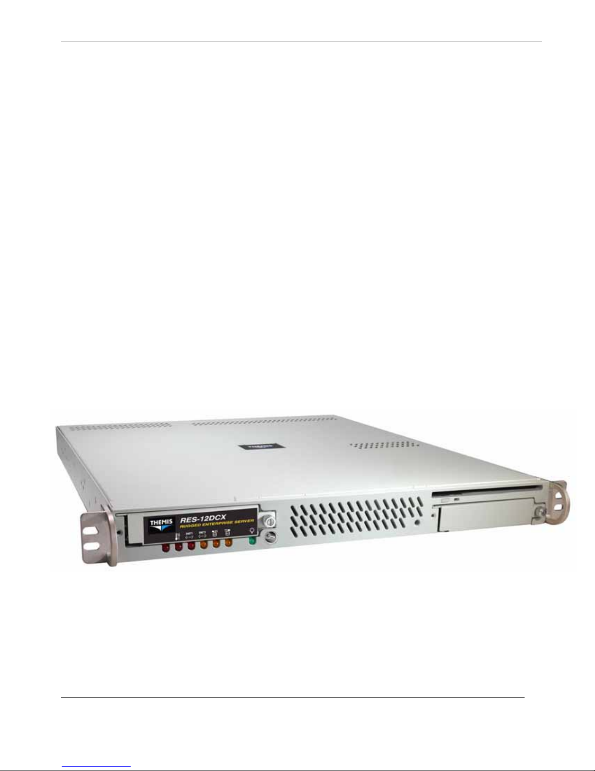
This document, entitled RES-12DCX Installation Guide, provides instructions on
how to install, configure, power up, boot, and perform diagnostics on the Themis
Rugged Enterprise Server RES-12DCX (see photo below), which is based on two
dual-core/quad-core 64-bit Intel® Xeon
an experienced system administrator with a knowledge of both networking and highspeed server systems.
TM
CPUs. These instructions are intended for
The 1RU-high (1.75”) RES-12DCX has been designed to fit into a standard 19” rack
and is provided with rack-mount brackets without handles. Optional rack-mount
brackets with handles and optional rack-mount slides are also available. The RES-
Themis Computer
Rugged Enterprise Server Model RES-12DCX
xxiii
Page 26

RES-12DCX Installation Manual
12DCX is rugged enough to withstand extreme shock (up to 25G), temperature (up
to 50°C), and EMI such as that associated with such demanding markets as the military, aerospace, and telecommunications industries.
The two dual-core/quad-core Intel Xeon CPUs are installed within 771-pin LGA
(Land-Grid Array) sockets, operate up to 2.67 GHz (dual-core) or 1.86 GHz (quadcore), and have a 1333-MHz front-side bus (FSB) or system bus. The RES-12DCX
supports up to 32 GB of 667/533-MHz DDR2 ECC FB-DIMM memory modules,
installed within eight 240-pin DIMM sockets.
The RES-12DCX is based on the functionality and capability of the Intel 5000P
(Blackford) chipset, which consists of the following three devices:
An overview of RES-12DCX design and specifications is given in Chapter 1, "Overview and Specifications", of this manual.
• Intel 5000P Memory Controller Hub (MCH)
• Intel 6321 ESB2 (Enterprise South Bridge 2) I/O Controller Hub (ICH)
• Intel 6700PXH 64-bit PCI-X Hub (PXH-V)
Website Information
Themis Computer corporate and product information may be accessed on the World
Wide Web by browsing the website http://www.themis.com.
Your Comments are Welcome
We are interested in improving our documentation and welcome your comments and
suggestions. You can email your comments to us at [email protected].
Please include the document part number in the subject line of your email.
xxiv
Themis Computer
Page 27
Preface
Notes, Cautions, Warnings, and Sidebars
The following icons and formatted text are included in this document for the reasons
described:
Note: A note provides additional information concerning the procedure or action
being described.
Caution: A caution describes a procedure or action that may result in injury to the operator or equipment. This may involve—but is not restricted to—heavy equipment or
sharp objects. To reduce the risk, follow the instructions accompanying this symbol.
Warning: A warning describes a procedure or action that may cause injury to the
operator or equipment as a result of hazardous voltages. To reduce the risk of electrical shock and danger, follow the instructions accompanying this symbol.
Sidebar: A “sidebar” adds detail to the section within which it is placed,
but is not absolutely vital to the description or procedure of the section.
Themis Computer
xxv
Page 28

RES-12DCX Installation Manual
xxvi
Themis Computer
Page 29
General
Section
1.1 Overview
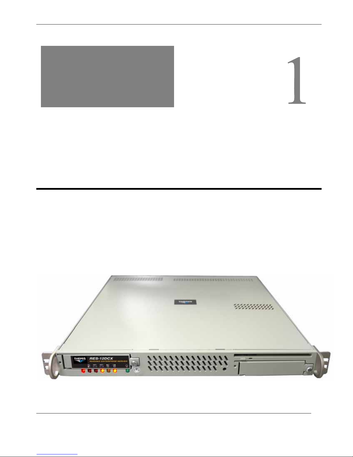
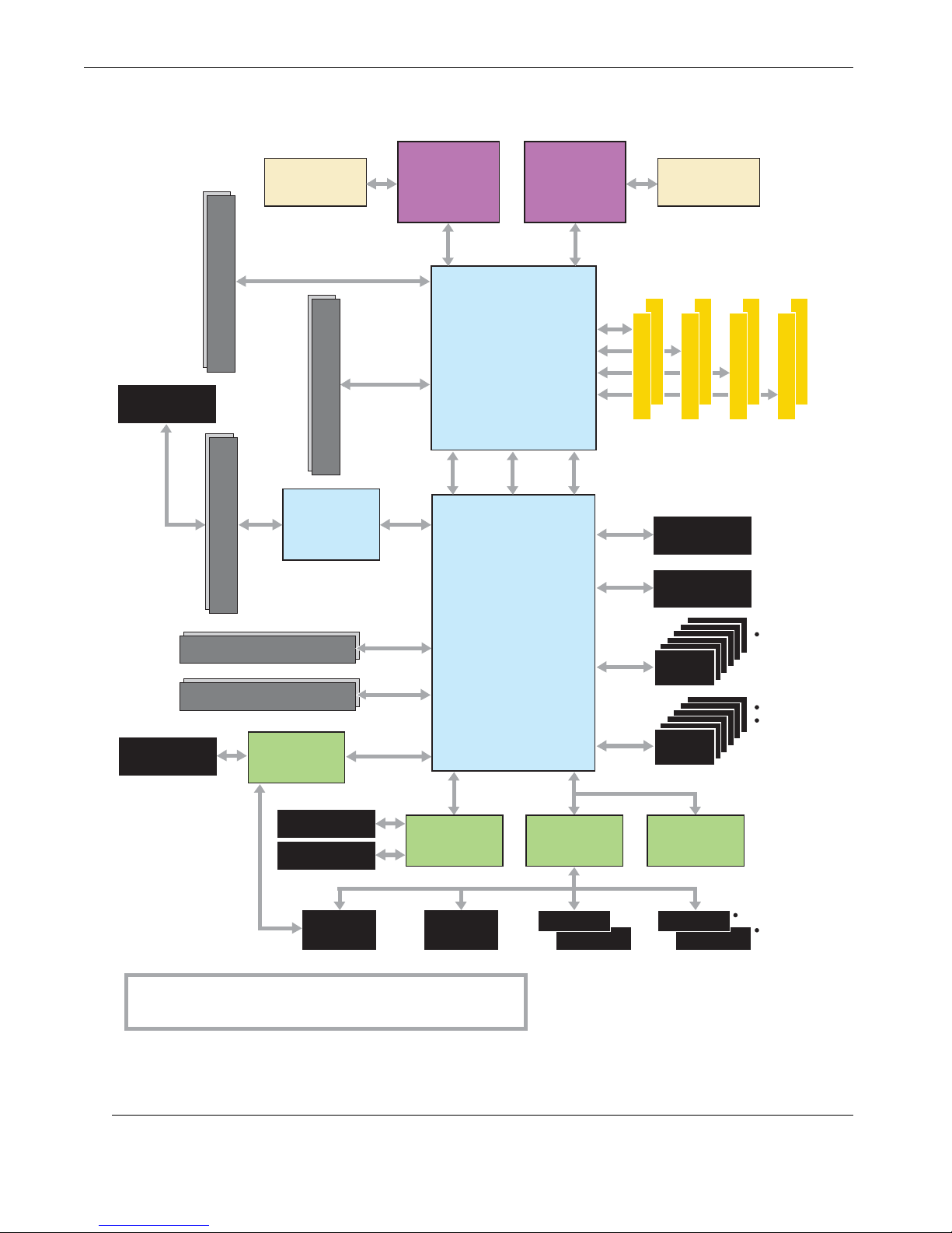
The RES-12DCX (see Figure 1-1 and Figure 1-2, page 1-2) is a rack-mounted system designed specifically for above-average shock and vibration environments. The
RES-12DCX supports single or dual Intel® 771-pin LGA XeonTM 64-bit dual/quadcore processors (each 2.67/1.86 GHz with a 1333-MHz system bus), and contains a
combination of computer- and graphics-intensive and diverse-I/O capabilities, ideal
for a variety of military/aerospace and commercial telecommunications applications.
Chapter
1RES-12DCX
Overview and Specifications
Themis Computer
Figure 1-1. RES-12DCX (with Rack Mounts)
1-1
Page 30
RES-12DCX Installation Manual
J5
PCI-Express (x4) Expansion Slot
L1
Serial-Attached
SCSI (SAS)
J12
Intersil ISL6307
Voltage-Regulator
Module
PCI-Express (x8)
J14
PCI-Express (x4) Expansion Slot
L2
64 bit
LSB
PCI-Express (x8)
MSB
CPU-2 CPU-1
Intel Xeon
Processor
[Dual/Quad Core]
2.67 GHz (Dual Core)
1.86 GHz (Quad Core)
TM
Intel Xeon
[Dual/Quad Core]
2.67 GHz (Dual Core)
1.86 GHz (Quad Core)
1066/1333 MT/secFSB FSB 1066/1333 MT/sec
64 bit
Intel
5000P
Memory Controller
Hub (MCH)
PCI-E (x4)
PCI-E (x4) PCI-E (x4)
Processor
TM
Channel
0
1
2
3
Intersil ISL6307
Voltage-Regulator
Module
FBD DIMM 1
FBD DIMM 0
FBD DIMM 0
FBD DIMM 1
FBD DIMM 1
FBD DIMM 0
FBD DIMM 1
FBD DIMM 0
PCI-X,
133 MHz
Intel 6700PXH
64-bit PCI Hub
PCI-E (x4)
I/O Subsystem
(PXH-V)
PCI-X (ZCR) Expansion Slot
L1
PCI-Express Expansion Slot
PCI-E (x8)
PCI-X , 133 MHz
I/O Controller Hub
South Bridge 2 (ESB2)
PCI-X Expansion Slot
LJ9
VGA
Connector
ATI ES1000
VGA Graphics
Controller
RJ45 Connector
PCI, 32 bit, 33 MHz
16 MB
Kumera n
Interface
Intel Gilgal
Dual Gigabit
RJ45 Connector
SIM SO-DIMM
IPMI Socket
Notes
* LPC = Low Pin Count
LSB = Least-Significant Bit
MSB = Most-Significant Bit SO-DIMM = Small Outline Dual In-Line Memory Module
PCI-E = PCI-Express
IPMI = Intelligent Platform Management Interface
LAN Ports
Floppy
Disk Drive
Intel
6321ESB
Winbond
W83627HF
LPC Super I/O
Keyboard
Mouse
ATA 100
Ebus
3.0 Gb/s
USB 2.0
LPC Bus
IDE
Connector
Ebus
Connector
SATA
Connector
USB
Connector
Firmware
Hub
COM 1
COM 2
6 Headers
5
4
3
2
1
0
2 Ports
4 Headers
5
4
3
2
1
0
Por t
Header
1-2
Figure 1-2. RES-12DCX System Block Diagram
Themis Computer
Page 31
Overview and Specifications
Overview
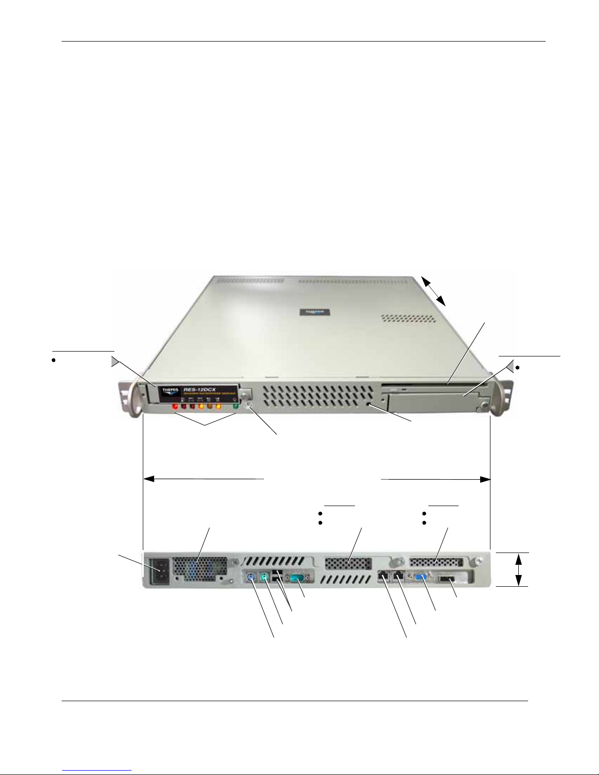
The RES-12DCX is designed within a 1RU-high (1.75”) form-factor 20” (50.8 cm)
deep and 17” (43.2 cm) wide (which, with mounting brackets, fits a 19”-wide rack)—
see Figure 1-3. Usable I/O expansion is supported through two horizontal PCI slots
mounted on PCI Riser Cards inserted into Slot 6, Slot 7, and one or more of the three
PCI-Express slots of the motherboard. Slot 6 can accommodate a full-length (12.28”)
card and Slot 7 a half-length (6.87”) card.
Depending on the Riser Card selected, PCI-card configurations include:
•Two PCI-Express (x8) cards
• Two PCI-X cards, one 133 MHz (Slot 6) and one 100 MHz, ZCR (Slot 7)
•One PCI-Express (x8) card and one 100-MHz, 64-bit (Slot 7) or 133-MHz, 64-
bit (Slot 6) PCI-X card (see Figure 1-3)
20” (50.8 cm) deep
CD-RW/DVD-ROM
Combo Slimline Drive
1 Hard-Disk Drive
SATA ID 0 (Boot)
AC Power Socket
(3-prong NEMA 15)
Front LED Indicator Panel
(see Figure 1-5)
Power Supply with
Twin-Fan Air Exhaust
Front View
System Power
On/Off Switch
17” (43.2 cm), 19” with Rack Mounts
PCI Slot 7
PCI-Express (x8)
PCI-X (ZCR), 100 MHz
or or
Rear View
COM Port 1
USB Port 0 (bottom), Port 1 (top)
PS/2 Mouse Port
PS/2 Keyboard Port
1 Hard-Disk Drive
SATA II ID 1
Reset
Switch
PCI Slot 6
PCI-Express (x8)
PCI-X, 133 MHz
1.75”
(1RU)
SAS Ports 4 through 7
VGA Display Port
Gigabit Ethernet LAN 2
Gigabit Ethernet LAN 1
Figure 1-3. External Features of the RES-12DCX (Front and Rear)
Themis Computer
1-3
Page 32
RES-12DCX Installation Manual
The RES-12DCX front panel houses two removable SATA II hard-disk drive bays
(one on the left and one on the right).
Also included on the front panel is a combination CD-RW/DVD-ROM Slimline
drive, a reset switch, and the system power switch and status LEDs (see Figure 1-5
on page 1-10). The rear panel contains blank I/O faceplates for two PCI cards
(graphics, NIC, etc.), an AC power supply with power-cord socket (DC can also be
ordered), and all I/O connectors (Figure 1-5 on page 1-10).
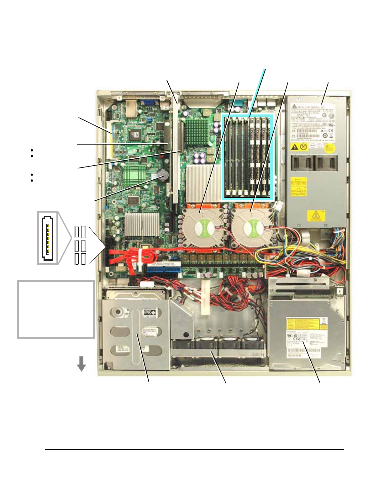
Major features of the RES-12DCX are described in Table 1-1. Major internal components can be seen in the open top view (cover removed) of Figure 1-4 on
page 1-6.
Feature Details
Table 1-1. Major Features of the RES-12DCX
Processor (CPU)
Chipset
Memory
Expansion slots
Peripheral Support
External I/O
(through rear I/O Panel)
z Two dual-core Intel 771-pin Xeon CPUs @ up to 2.33 GHz
z 2-MB or 4-MB L2 cache (per core)
z 667/1066/1333 MHz front-side system bus speed
z On-board Voltage-Regulator Module (per processor)
z Intel chipset:
— Memory Controller Hub (MCH)
— 6700 PCI-X Hub (PXH-V)
— Enterprise SouthBridge 6321 I/O Controller Hub (ICH)
z Eight 240-pin DIMM sockets supporting up to 32 GB of registered ECC DDR2
FBD 667/533 SDRAM
The following 2 PCI slots are horizontally located on a PCI Riser Card (one
Riser Card per PCI slot) installed in slot 6, slot 7, and one to three PCI-Express
slots (each slot is PCI Riser-Card dependent):
z Left Slot (Slot 6):PCI-Express (x8) or PCI-X (64 bit, 133-MHz)
z Right Slot (Slot 7):PCI-Express (x8) or PCI-X (64 bit, 100-MHz) with ZCR
support
z Two removable SATA II hard-disk drives
z One combination CD-RW/DVD-ROM slimline (IDE) drive
z 1 PS/2 keyboard port (DIN-6) and 1 PS/2 mouse port (DIN-6)
z 2 USB 2.0 ports—USB 0 and USB 1
z 1 serial port (9-pin)—COM 1
z 2 RJ45 Gigabit Ethernet ports—LAN 1 and LAN 2
z 1 VGA display port
z 4 SAS (Serial-Attached SCSI) ports (single connector)—SAS 4 through SAS 7
1-4
Themis Computer
Page 33
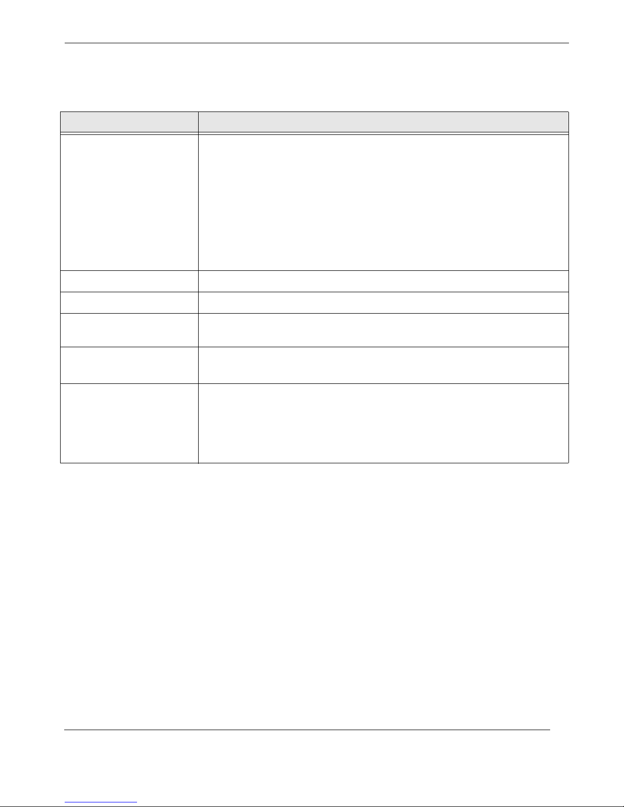
Table 1-1. Major Features of the RES-12DCX (Continued)
Feature Details
Overview and Specifications
Overview
Internal I/O
a
(through on-board
headers or connectors)
Operating temperature
Shock endurance
Dimensions
Rack-mount brackets and
slides
One power supply
(AC or DC)
z 4 USB 2.0 ports through on-board headers—USB 2 through USB 5
z 1 serial port through on-board header (9-pin)—COM 2
z 6 internal SATA II port connectors—SATA 0 through SATA 5
z 4 SAS (Serial-Attached SCSI) ports through a single connector
—SAS 0 through SAS 3
z 1 Floppy-Drive port connector (Black)
z 2 IDE connectors—Primary (Blue)
—Secondary (White) for Compact Flash card use only
z 1 SIM SO-DIMM IPMI (Intelligent Platform Management Interface) socket
z 0°C to 50°C
z 25G @ 20-msec duration
z 1.75” (1RU) high, 17” (43.2 cm) wide (19”/48.3 cm with mounting brackets),
20” (50.8 cm) deep
z Choice of rack-mount brackets with handles
z Optional rack-mount slides
AC Output
z 650 watts, auto-ranging (100–240 VAC; 47 to 63 Hertz)
z Filtered, fuse-protected AC socket
DC Output
z 300 watts
a—Unless cabled, connected, and tested during initial product assembly, internal I/O is not supported by the RES-12DCX.
Themis Computer
1-5
Page 34
RES-12DCX Installation Manual
SIM SO-DIMM IPMI Socket
PCI Slot 6
PCI-Express (x8)
PCI-X (64 bit, 133 MHz)or
PCI Slot 7
PCI-Express (x8)
PCI-X (64 bit, 100 MHz)or
Riser Card
Riser Card
Lithium Battery (3V)
SATA Ports
1
01
23
7
45
PCI Riser-Card Retainer Bracket
DIMM Memory Modules (8)
CPU 2 (with Fan) CPU 1 (with Fan)
AC Power Supply
(DC also available)
Note on PCI-Slot Availability
Because of the 1RU height
restriction of the RES-12DCX,
PCI cards must be installed in
the horizontal position through
the use of a PCI Riser Card.
As a result, only 2 PCI cards
can be installed.
See Chapter 2 for more details.
Front
1-6
SATA-II Disk-Drive
Housing
Fan Assembly Housing
(Four 38-mm Fans)
CD/DVD
Combo-Drive
Housing
Figure 1-4. Major Components of the RES-12DCX (Open Top View)
Themis Computer
Page 35

1.1.1 Special Features
1.1.1.1 Recovery from AC Power Loss
The BIOS setup can be configured to allow the system, whenever AC power is lost,
• to remain off (in which case, the power switch must be activated by the user) or
• return to a power-on state automatically when power is restored.
The system default is “Always On”.
1.1.1.2 Voltage Monitors
A built-in voltage monitor continually scans multiple voltages (CPU cores, memory,
chipset, +1.8V, +3.3V, +5V, +12V, –12V, +3.3V Standby, +5V Standby, and Vbat)
on the motherboard. If a voltage becomes unstable, it issues a warning or sends an
error message to the screen.
Overview and Specifications
Overview
Voltage thresholds can be adjusted through the PC health-monitor utility to define
the sensitivity of the voltage monitor.
1.1.1.3 Fan Status Monitor
The RES-12DCX has eight cooling fans—four 38-mm fans within one fan assembly
at the front of the system, one on each CPU, and two within the single power supply.
The PC health-monitor utility can be used to check the RPM status of cooling fans.
The onboard CPU and chassis fans are controlled by Thermal Management via the
BIOS (under Hardware Monitoring in the Advance Setting).
1.1.1.4 Environmental Temperature Control
The thermal-control sensor monitors CPU temperature in real time and will activate
the thermal control fan when CPU temperature exceeds a user-defined threshold.
Overheat circuitry operates independently from the CPU, and can continue to monitor overheat conditions even when the CPU is in sleep mode.
Once the thermal sensor detects a CPU temperature that is above the set threshold, it
automatically turns on the thermal control fan to prevent overheat damage to the
CPU. In addition, onboard chassis thermal circuitry can monitor overall system temperature and alert users when chassis temperature exceeds a user-defined threshold.
Themis Computer
1-7
Page 36

RES-12DCX Installation Manual
1.1.1.5 CPU Overheat LED and Control
This feature is enabled by the user through the CPU overheat warning function in the
BIOS. With it, the user can define an overheat temperature that, when exceeded,
activates the overheat fan and the Overheat warning LED.
1.1.1.6 System Resource Alert (optional)
Available only through Supero Doctor III in the Windows OS environment or
Supero Doctor II in Linux (an optional third-party product), this feature is used to
notify the user of certain system events. For example, if the system is running low on
virtual memory and there is insufficient hard disk-drive space for saving the data, an
alert will be issued warning of the potential problem.
Supero Doctor can also be configured to provide warnings when the system temperature goes beyond a pre-defined range.
1.1.1.7 IPMI Module Support
The RES-12DCX motherboard contains a special SIM Low Profile IPMI 2.0 slot
(see Figure 1-4) to install an optional Intelligent Platform Management Interface
(IPMI) module. This invaluable health-monitoring tool provides full SNMP (including SNMP trap), some power cycle functions (reboot and graceful shutdown), and
the ability to control other servers. [This module must be installed at the factory.]
Detailed information on IPMI may be obtained from the following website:
http://www.intel.com/design/servers/ipmi/.
1.1.1.8 CPU Fan Auto-Off in Sleep (Doze) Mode
The CPU fan activates when power is turned on, and continues to operate when the
system enters Standby mode. In Sleep mode, the CPU will not run at full power,
generating less heat. Sleep settings are made through the PC health-monitor utility.
1.1.2 ACPI Features
Advanced Configuration and Power Interface (ACPI) defines a flexible and abstract
hardware interface that provides a standard method of integrating power management features throughout the system. This includes the hardware, the operating system, and the application software. As a result, the system can automatically turn
peripherals (CD-ROMs, NICs, hard-disk drives, and printers, for example) on or off.
This includes any consumer devices that may be connected to the system (VCRs,
1-8
Themis Computer
Page 37

TVs, telephones, and stereo systems, for example).
In addition to providing operating-system power management, ACPI offers a
generic system event mechanism for Plug and Play and an operating-systemindependent interface for configuration control. Plug-and-Play BIOS data structures
are leveraged, while the implementation is processor-architecture-independent and
compatible with both Windows 2000, Windows XP, and Windows 2003 Server
Operating Systems.
1.1.2.1 Suspend-State Indicator
When the CPU enters a suspend state, the Power LED will start blinking to indicate
that the CPU is in suspend mode. Pressing any key on the keyboard will awaken the
CPU, at which time the power LED will stop blinking and remain on.
1.1.2.2 Main Switch Override
Overview and Specifications
Overview
ATX 2.01 (or higher)-compliant power supply only. If enabled in the system setup,
the RES-12DCX power button on the front of the unit functions as a suspend button
to make the system enter a SoftOff state. The monitor is suspended, and the hard
drive will spin down. Pressing the power button again will cause the system to
awaken.
During the SoftOff state, the ATX power supply provides only enough power to
keep the minimum required circuitry alive. If you want to turn the power off completely, in the event of a system malfunction, for example, depress and hold the
power button for four (4) seconds. The system will turn off completely with no
power to the motherboard provided.
This option can be set in the Power section of the BIOS Setup routine.
1.1.2.3 External Modem Ring-On
ATX 2.01 (or higher)-compliant power supply only. When the system is in the
SoftOff state, it can be awakened by the ringing of an external modem. This feature can only be provided if “External Modem Ring-On” is included in the installed
modem card and the corresponding setting is enabled in the system BIOS settings.
1.1.2.4 Wake-On-LAN (WOL)
ATX 2.01-compliant (or higher) power supply only. The Wake-On-LAN utility
enables a management application to remotely power up a computer that has been
powered off. This allows remote PC setup, updates, and asset tracking to occur after
Themis Computer
1-9
Page 38
RES-12DCX Installation Manual
hours and on weekends, so that daily LAN traffic is kept to a minimum and users are
uninterrupted.
The motherboard employs a 3-pin header (Wake-On-LAN or WOL) to connect to
the 3-pin header of any Network Interface Card (NIC) with WOL capability. In addition, an onboard LAN controller can also support WOL without any connection to
the WOL header. The 3-pin WOL header is intended to be used with a LAN add-on
card only.
Wake-On-LAN must be enabled in BIOS.
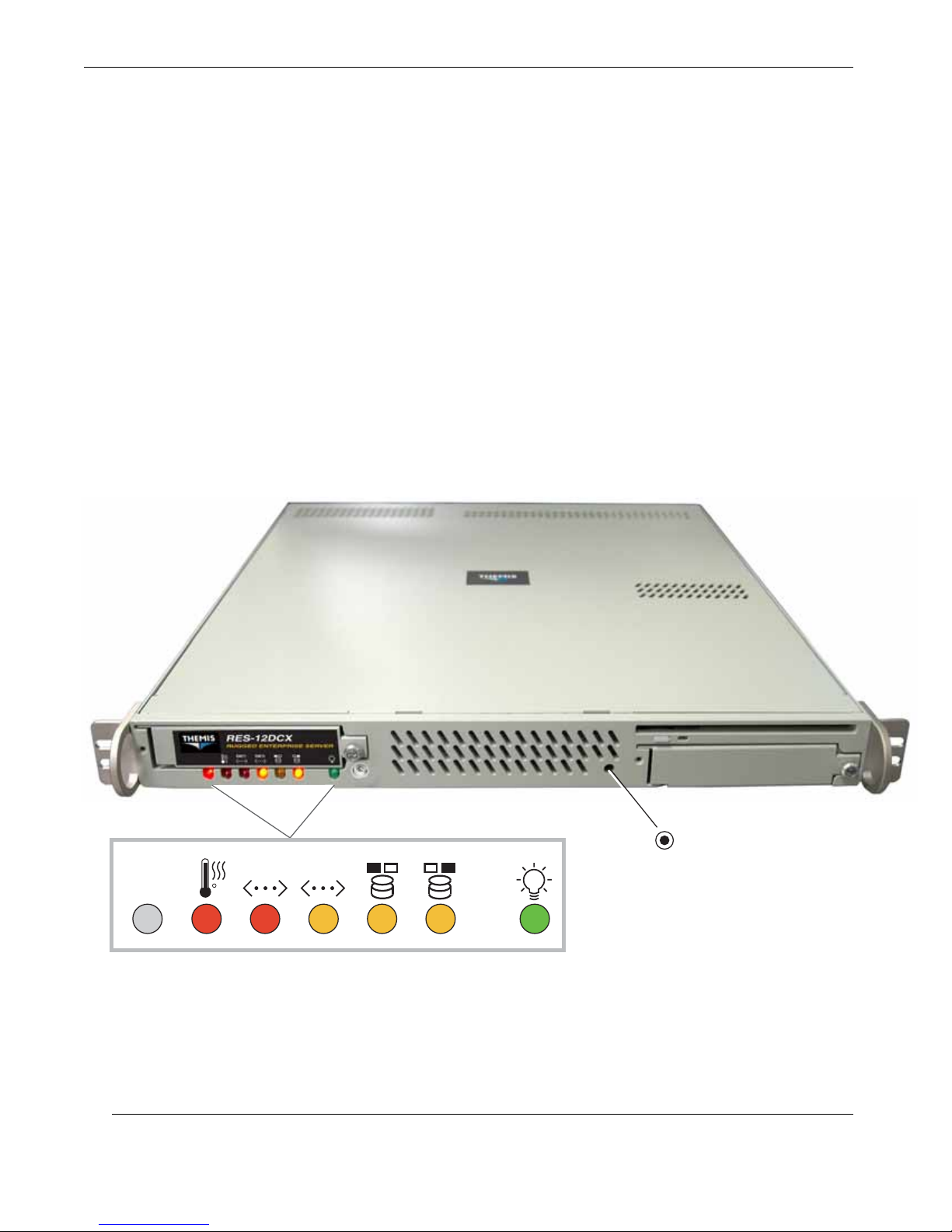
1.1.3 System LEDs
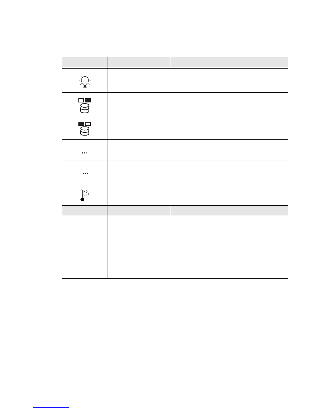
All RES-12DCX system LEDs are located on the front panel (see Figure 1-5). LEDs
are described in Table 1-2 on page 1-11.
ENET1 ENET2
C
LAN 1 LAN 2 Drive 1
1-10
LEDs
Drive 0
Left
Right
Figure 1-5. RES-12DCX System LEDs
Powe rOverheat
Reset
Switch
Themis Computer
Page 39
Overview and Specifications
ENET
Table 1-2. System LEDs
Symbol Front Panel LEDs Description
Overview
2
ENET1
<>
C
Power
Right Hard-Disk Drive
Left Hard-Disk Drive
a
NIC2
(Gbit Ethernet) z Indicates network activity on LAN 2.
NIC1 (Gbit Ethernet)
Overheat/Fan Fail
z Indicates that the system is turned on.
z Indicates SATA II hard-drive activity.
z Indicates SATA II hard-drive activity.
z Indicates network activity on LAN 1.
z Warns that the system is exceeding specified
temperature parameters.
Symbol Rear Panel LEDs Description
Each Ethernet port contains two LEDs:
z The color of the left LED (when facing the port)
indicates the LAN connection speed:
N/A LAN1 and LAN2
- Off = No connection or 10 Mbps
- Green = 100 Mbps
- Amber = 1 Gbps
z The right LED, when blinking green, indicates
LAN activity. OFF indicates no activity.
a—NIC = Network Interface Controller.
Themis Computer
1-11
Page 40

RES-12DCX Installation Manual
1.2 Chipset Overview
Built upon the functionality and the capability of the Intel 5000P (Blackford)
chipset, the RES-12DCX provides the performance and feature set required for dual
processor-based servers, including optimal configuration options for communications, presentation, storage, computation or database applications. The 5000P
chipset supports single or dual Xeon 64-bit dual-core and quad-core processors with
front-side bus speeds of up to 1.333 GHz. The Intel chipset consists of:
• the 5000P Memory Controller Hub (MCH)
• the Intel 6321 Enterprise South Bridge 2 (ESB2) I/O Controller Hub (ICH)
• the 6700 PCI-X 64-bit hub (PXH-V)
In addition, a Super I/O Controller chip offers a range of functions to increase the
I/O capability of the system.
1.2.1 The Intel 5000P Memory Controller Hub (MCH)
The 5000P Memory Controller Hub (MCH) chipset is designed for symmetric multiprocessing across two independent front side bus interfaces. Each front side bus uses
a 64-bit wide, 1.333 GHz data bus that transfers data at 10.7 GB/sec (for a total
bandwidth of 21.3 GB/sec.)
The MCH provides four channels of Fully-Buffered DIMM (FB-DIMM) memory.
Each of these channels can support up to four Dual Ranked FB-DIMM DDR2
DIMMs. FB-DIMM memory channels are organized in to two branches for support
of RAID 1 (mirroring). The RES-12DCX MCH chipset connects up to 8 fully-buffered DIMM modules, providing a total of 32.0 GB/s for DDR2 667/533 FBD ECC
memory. The MCH chipset also provides three x4 PCI-Express interfaces to the
ESB2. In addition, the 5000P chipset offers a wide range of RAS features, including
memory interface ECC, x4/x8 Single Device Data Correction, CRC, parity protection, memory mirroring, and memory sparing.
The Xeon dual-core processor is designed to be used in conjunction with the chipset,
and provides the following features:
• L1 Cache Size: Instruction Cache (32KB/16KB), Data Cache (32KB/24KB)
• L2 Cache Size: 4MB (2MB per core)
• Data Bus Transfer Rate: 8.5 GB/s
• Package: FC-LGA6/FC-LGA4, 771 Lands
1-12
Themis Computer
Page 41

Overview and Specifications
1.2.2 The Intel 6321 ESB I/O Controller Hub (ICH)
The Intel 6321 ESB I/O Controller Hub integrates an Ultra ATA 100 controller, six
Serial ATA host controller ports, one EHCI host controller, and four UHCI host controllers supporting eight external USB 2.0 ports, LPC interface controller, flash
BIOS interface controller, PCI interface controller, Azalia / AC’97 digital controller,
integrated LAN controller, an ASF controller and a ESI for communication with the
MCH.
The Intel 6321 ESB I/O Controller Hub component provides the data buffering and
interface arbitration required to ensure that system interfaces operate efficiently and
provide the bandwidth necessary to enable the system to obtain peak performance.
The Intel 6321 ESB I/O Controller Hub elevates Serial ATA storage performance to
the next level with Intel® RAID.
The ACPI compliant Intel 6321 ESB I/O Controller Hub platform can support the
Full-on, Stop Grant, Suspend to RAM, Suspend to Disk, and Soft-Off power management states. Through the use of the integrated LAN functions, the Intel 6321 ESB
I/O Controller Hub also supports Alert Standard Format for remote management.
Chipset Overview
1.2.3 The Intel 6700 PCI-X 64-bit Hub (PXH-V)
The Intel 6700 PCI-X 64-bit hub (PXH-V) attaches directly to the MCH through a
point-to-point PCI-Express x8 or x4 link for support of PCI and PCI-X interfaces on
the platform. Each 6700PXH 64-bit PCI hub supports two bus segments that can be
independently configured to operate in PCI (33 MHz of 66 MHz) or PCI-X mode (at
66, 100, or 133 MHz) for 32-bit or 64-bit PCI/PCI-X devices.
Each PCI/PCI-X interface integrates a PCI standard hot-plug controller. The hub
supports multiple PCI-X slots and frequencies for the high-bandwidth I/O connectivity required for today’s server market.
1.2.4 Super I/O Controller
The Super I/O Controller chip disk-drive adapter functions include:
• a floppy disk drive controller (industry standard 82077/765 compatible)
• a data separator
• write pre-compensation circuitry
• decode logic
• data rate selection
Themis Computer
1-13
Page 42

RES-12DCX Installation Manual
• clock generator
• drive interface control logic
• interrupt and DMA logic
The wide range of functions integrated onto the Super I/O greatly reduces the num-
ber of components required for interfacing with floppy disk drives. The Super I/O
supports two 360K, 720K, 1.2M, 1.44M or 2.88M disk drives, and data-transfer
rates of 250 Kb/s, 500 Kb/s or 1 Mb/s.
It also provides two high-speed, 16550-compatible serial communication ports
(UARTs). Each UART includes a 16-byte send/receive FIFO, a programmable
baud-rate generator, complete modem control capability, and a processor interrupt
system. Both UARTs provide legacy speed with baud rates of up to 115.2 Kbps, as
well as an advanced speed with baud rates of 250K, 500K, or 1 Mb/s (for higher
speed modems).
The Super I/O supports one PC-compatible printer port (SPP), Bi-directional Printer
Port (BPP), Enhanced Parallel Port (EPP), or Extended Capabilities Port (ECP).
Advanced Configuration and Power Interface (ACPI) compliant functions support
legacy and ACPI power management through an SMI or SCI function pin. An autopower-management feature reduces power consumption.
1-14
Themis Computer
Page 43

1.3 Specifications
1.3.1 General
Table 1-3 lists general specifications for the RES-12DCX.
Table 1-3. RES-12DCX General Specifications
Parameter Description
Overview and Specifications
Specifications
Dimensions
Weight
19” Rack-Mountable
with Slide capability
Temperature
Operating:
Non-Operating:
Relative Humidity
Operating:
Non-Operating:
Maximum Wet Bulb
Operating:
Non-Operating:
z 1.75” (1RU) high
z 17” (43.2 cm) wide
z 20” (50.8 cm) deep
z Under 18 pounds (8.2 kg), includes 1 CD-RW/DVD-ROM drive,
2 SATA II hard-disk drives, and 1 power supply
z Add 8.5 pounds (4 kg) for the shipping container and one AC
power cord
z The manual and associated shippi ng paperwork weighs approx-
imately 1 lb (0.5 kg)
z Left and right rack-mount tabs (3 screws each ) inc lud ed w ith
chassis. Rack-mount slides are optional.
z 0°C to +50°C
z –40°C to +70°C
z 8% to 90% non-condensing
z 5% to 95% non-condensing
z 27°C, non-condensing
z 35°C, non-condensing
Altitude
Operating:
Non-Operating
Themis Computer
z 0 to 10,000 feet above sea level
z 0 to 40,000 feet above sea level
1-15
Page 44
RES-12DCX Installation Manual
1.3.2 Electrical
Table 1-4 lists the electrical specifications for the RES-12DCX.
Table 1-4. RES-12DCX Electrical Specifications
Parameter Description
Input Power
Input Current
Input Frequency
Input Voltage
Input VA Rating
BTU Rating
Power Factor
Input Leakage
Plug Type
1.3.2.1 System Power
The RES-12DCX can be ordered with an AC power supply (default) or a DC power
supply. The type of power supply must be specified in the original order.
AC Power Supply
The AC power supply has a 650-watt output capacity that auto-ranges single-phase
AC input from a 100 to 240 VAC (47 to 63 Hertz) source.
z 390 watts
z 8 amperes (115V), 4 amperes (230V); 30 amperes peak
z 47–63 Hertz
z 100–240 VAC, internally fused
z 390 VA
z 760
z 0.99
z 6 mA maximum @240 VAC
z NEMA 5-15P
Filtered and fused (internal) AC is supplied from a rear-mounted power connection.
DC Power Supply
The DC power supply has a 300-watt output capacity.
1.3.2.2 Output Voltage
The RES-12DCX provides output voltages that are split between +3.3V, +5V,
+5Vsb, +12V, and -12V rails.
1-16
Themis Computer
Page 45
1.3.3 Environmental
1.3.3.1 Shock
The RES-12DCX is designed to survive an elevated shock environment. All structural components are welded together, enabling the system to survive a maximum
3-axis shock load of 25G at 20-msec duration.
1.3.3.2 Electrostatic Discharge
The RES-12DCX is designed to tolerate electrostatic pulses up to 15 kilovolts (KV)
with no impact on system operation.
1.3.3.3 Noise Level
Typical noise levels emitted by the RES-12DCX are outlined in Table 1-5. The chassis is installed with four 38-mm fans contained side-by-side in a single fan assembly.
Overview and Specifications
Specifications
Table 1-5. Typical Noise Levels of the RES-12DCX
Measured at: 1 Meter 2 Meters
Front 66.24 dB 57.57 dB
Rear 61.53 dB 57.93 dB
Themis Computer
1-17
Page 46

RES-12DCX Installation Manual
1.4 Packaging and Shipping
The RES-12DCX is packaged in a reusable shipping container. Approximate weight
of an empty container and one AC power cords is 8.5 pounds (4 kg).
The approximate weight of a RES-12DCX (loaded with a CD-RW/DVD-ROM
drive, two hard-disk drives, and one power supply) is under 18 pounds (8.2 kg).
The approximate weight of a manual and associated shipping paperwork is one
pound (0.5 kg).
Therefore, both the shipping container and a fully installed RES-12DCX including
power cord, manual, and associated paperwork, weigh under 28 pounds (12.7 kg).
1.4.1 Rack-Mount Slides (Optional)
Rack-Mount Slides can be mounted on each side of the RES-12DCX, for the purpose of sliding the unit in and out of a rack. Mounting slides are optional and can be
ordered at the time of purchase.
To learn how to install rack-mount slides, refer to Appendix B, “Rack-Mount Slide
Installation”, on page B-1.
1-18
Themis Computer
Page 47
2RES-12DCX
Installation
Section
This chapter describes:
• How to install a memory module, SATA-II hard-disk drive, PCI card, 38-mmfan housing, and lithium battery. [The power supply is not field-replaceable.]
Chapter
2
Installation and Operation
• Rack-mount brackets
• How to turn the RES-12DCX on and off
2.1 Installation Procedures
Caution: Use industry-standard ESD grounding techniques when handling all
components. Wear an antistatic wrist strap and use an ESD-protected mat. Store
ESD-sensitive components in antistatic bags before placing them on any surface.
Handle all IC cards by the front panel or edges only.
To install or replace a SATA-II hard-disk drive, skip the next section and proceed
directly to page 2-6. Replacement of motherboard components require removal of
the chassis protective cover.
2.1.1 Remove Protective Top Cover
To access a motherboard component, open the RES-12DCX as follows:
Themis Computer
2-1
Page 48
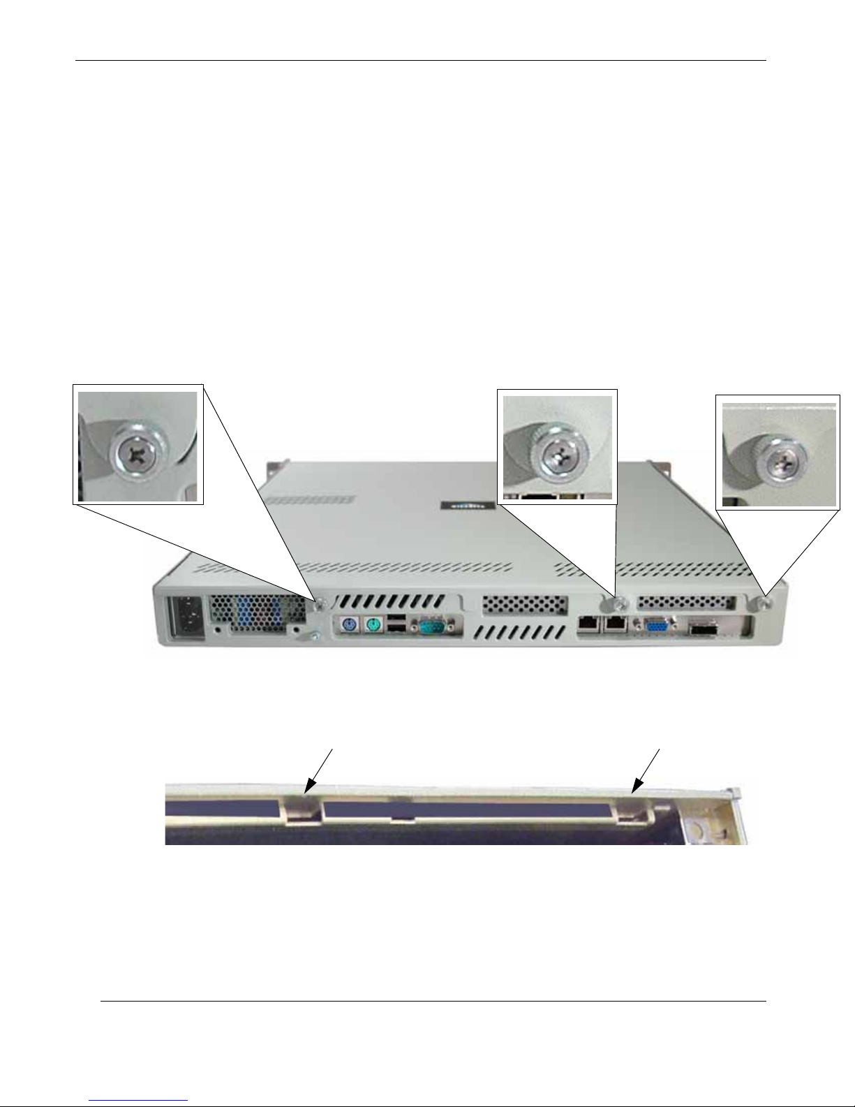
RES-12DCX Installation Manual
1. Loosen the three captive Phillips screws holding the protective top access
cover to the rear of the RES-12DCX chassis (see A, Figure 2-1).
2. Both the front and sides of the cover have flat hooks or tabs underneath that
fit under slots on the chassis top side edges (see B, Figure 2-1). Remove the
cover by sliding it toward the rear until it is free of these chassis slots.
3. Store the cover in a safe place until it is replaced.
4. Proceed to the appropriate section to install or replace a memory module
(page 2-3), PCI card (page 2-8), 38-mm-fan housing (page 2-12), or lithium
battery (page 2-14).
2-2
Rear View
Loosen the 2 captive access-cover screws . . .
A
Chassis slot
Left-side top edge
. . . and slide the top cover toward the rear until the top hooks and tabs clear all chassis slots
B
Chassis slot
Figure 2-1. Remove the RES-12DCX Protective Access Cover
Themis Computer
Page 49
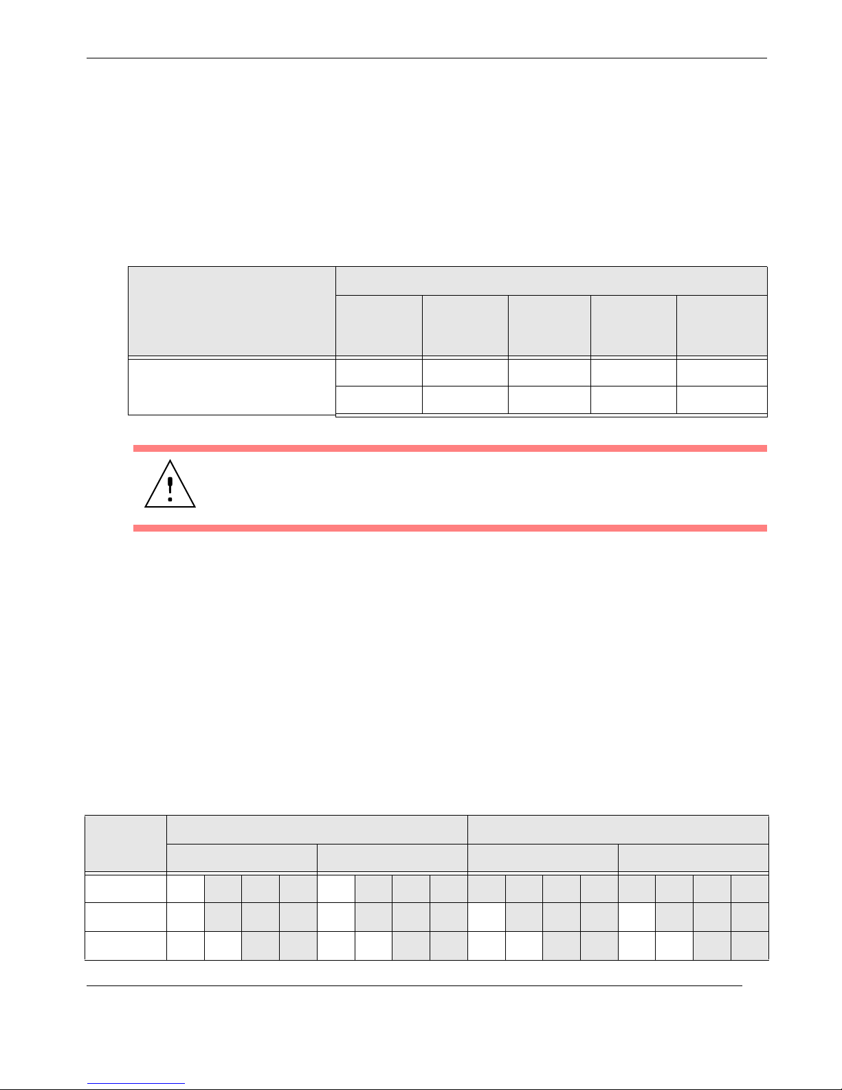
2.1.2 Memory Modules
The RES-12DCX supports up to eight registered ECC DDR2 Fully-buffered DIMM
(FBD) SDRAM Memory Modules, at data rates of either 667 or 533 million data
transfers per second, (see Table 2-1), up to a total memory capacity of 32 GB (see
Figure 2-2 on page 2-4).
Table 2-1. RES-12DCX Memory Modules
Installation and Operation
Installation Procedures
Memory
RES-12DCX
z Eight 240-pin DIMM Sockets
Caution: Exercise extreme caution when installing or removing FBD Memory
Modules to prevent any possible damage. Note that memory is interleaved to improve performance.
The dual-channel memory bus can support full-duplex memory bandwidth transfers
of up to 3.2 GB/s. When installing memory, follow these rules:
• Two modules must be installed at a time, starting with DIMM 1A and 1B
(Bank 1), then 2A and 2B (Bank 2), 3A and 3B (Bank 3), and finally 4A and
4B (Bank 4); see Table 2-2 and Figure 2-2 on page 2-4.
• It is strongly recommended that you do not mix memory modules of different
speeds and sizes. If DIMMs of different speeds have been installed, verify that
the BIOS setup is configured for the fastest speed of RAM used.
Peak
FBD Standard Capacity Speed
DDR2-667 PC2-5300 32 GB 2.67 GB/s 5.333 GB/s
DDR2-533 PC2-4200 32 GB 2.1 GB/s 4.266 GB/s
Transfer
Rate
• Make sure that the correct type of SDRAM is being used (see Table 2-1).
Other types of SDRAM are not supported.
Table 2-2. Optimized DIMM Configurations
Number
of DIMMs
2 1A
4 1A 2A 3A 4A
8 1A 1B 2A 2B 3A 3B 4A 4B
Themis Computer
Bank 1 (Channel 0) Bank 2 (Channel 1) Bank 3 (Channel 2) Bank 4 (Channel 3)
Branch 0 Branch 1
2A
2-3
Page 50
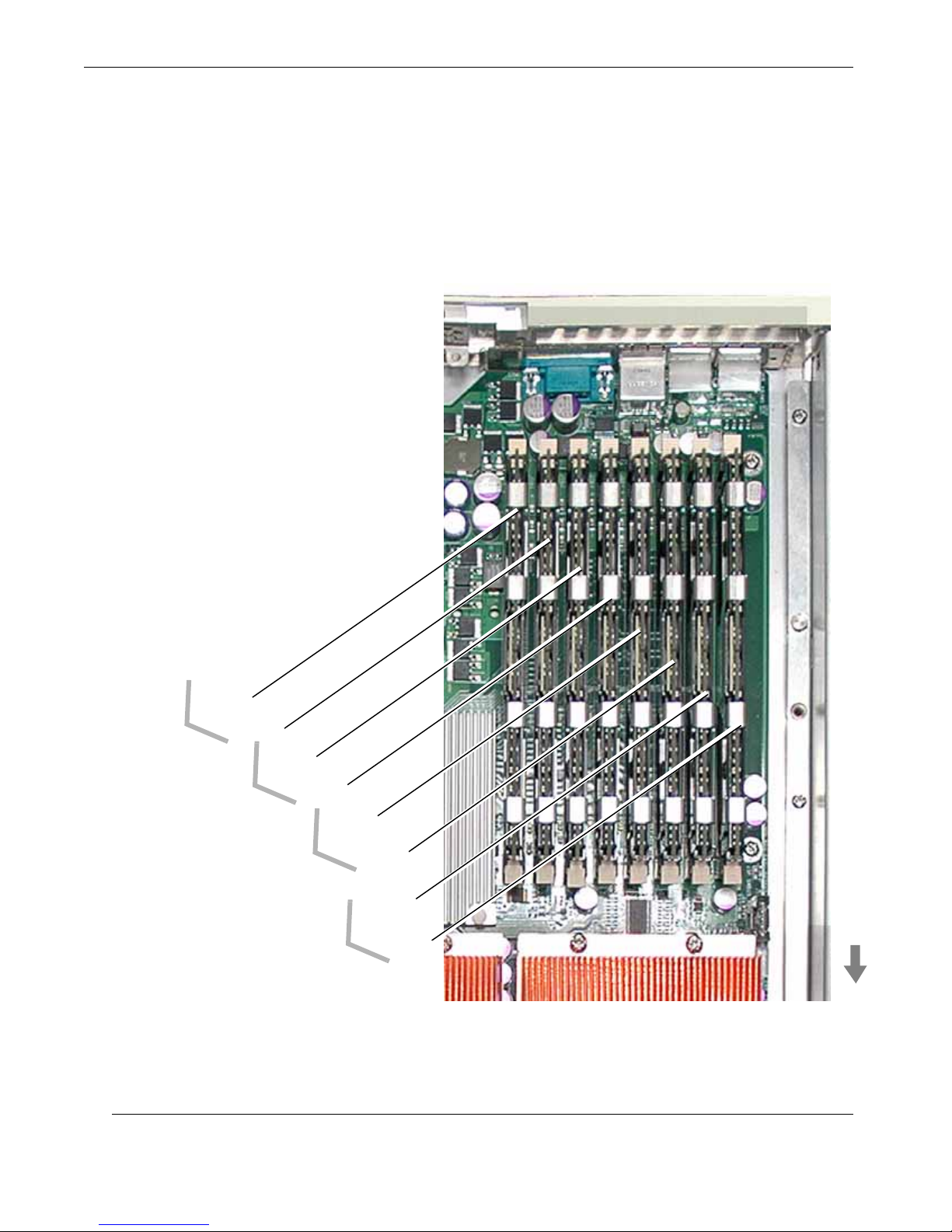
RES-12DCX Installation Manual
2.1.2.1 Installation
The following procedure explains how to install the DDR2 FBD Memory Modules.
1. Determine the location of the slot into which the Memory Module will be in-
stalled (see Figure 2-2).
DIMM 4B
DIMM 4A
Bank 1
DIMM 1A
DIMM 1B
Bank 2
DIMM 2A
DIMM 2B
Bank 3
DIMM 3A
Bank 4
DIMM 3B
DIMM 4A
DIMM 4B
Front
Figure 2-2. Memory Module Slot Location
2-4
Themis Computer
Page 51
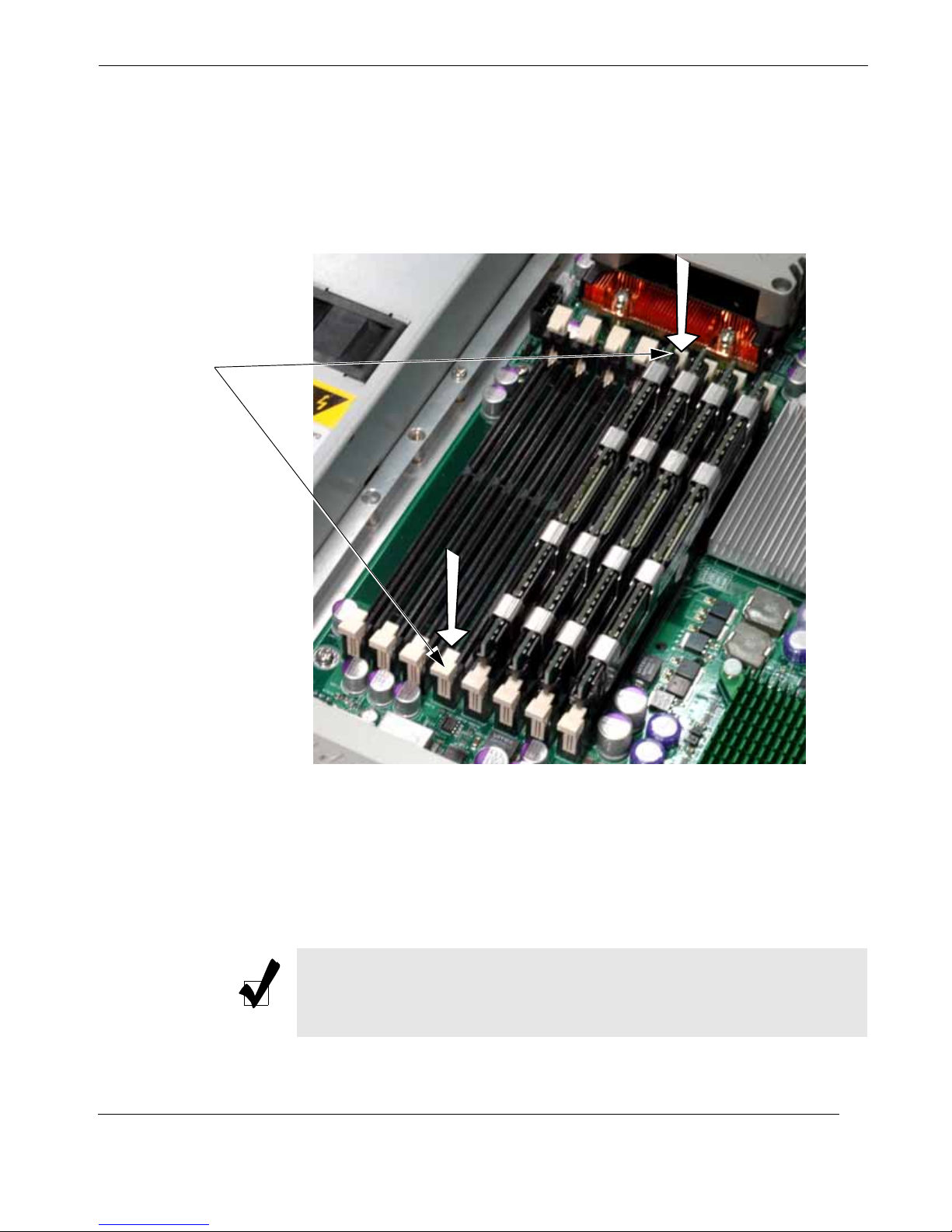
Press latch
downward &
outward at
each end
Installation and Operation
Installation Procedures
2. If a module is already seated in the slot you have selected for installation, re-
move it by gently pressing down and outward on the latches at both ends of
the slot (see Figure 2-3), then pulling the old module directly up from the slot
until it is free of the connector.
3. Before inserting a new memory module into the vacant slot, make sure that
the two latches are pulled outward away from the center of the slot.
With the latches in the outward position, gently insert the new module verti-
cally into its slot and press firmly downward until it snaps into place.
Note: Make sure the memory module has the proper orientation by aligning the alignment notch at the bottom edge with its counterpart ridge at
the bottom of the slot.
Themis Computer
Figure 2-3. Memory Module Removal
2-5
Page 52
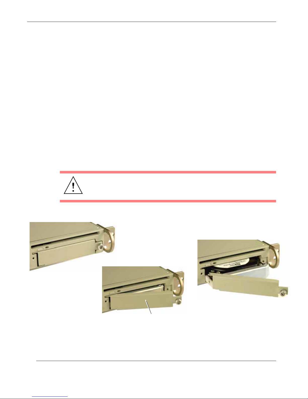
RES-12DCX Installation Manual
2.1.3 SATA-II Hard-Disk Drive
Perform the following steps to remove and install a SATA-II hard-disk drive.
2.1.3.1 Disk-Drive Removal
To remove a hard-disk drive,
1. Make sure the system is powered off (see “Operation” on page 2-16).
2. Locate the drive to be removed (see A in Figure 2-4).
3. Loosen the captive screw of the drive latch handle until it swings away from
the chassis (see B).
4. Carefully pull the latch handle (see C) until the drive has cleared the chassis.
The drive will automatically disconnect from its backplane connector when
pulled forward.
Caution: When pulling the hard-disk drive from the chassis, hold it at the
bottom to prevent it from falling and damaging the drive.
Locate the drive to be removed, . . .A
C
. . . and pull drive out with the latch handle
B
. . . loosen the drive latch handle, . . .
Latch Handle
2-6
Figure 2-4. RES-12DCX Hard-Disk Drive Removal
Themis Computer
Page 53
2.1.3.2 Disk-Drive Installation
To install a hard-disk drive,
1. Make sure the latch handle of the drive to be installed is in the open position.
2. Properly orient the new drive and insert it into the vacant drive slot. If the
drive cannot be inserted into the slot, rotate it 180 degrees (it is impossible to
install the drive incorrectly into its slot).
3. Push the drive toward the rear (DO NOT CLOSE the latch handle while push-
ing) until the drive is flush with the front of the chassis. The handle will swing
closed when it comes into contact with the RES-12DCX chassis.
4. When the drive is fully inserted into its slot, push the latch handle closed and
secure the captive screw to the chassis.
Installation and Operation
Installation Procedures
Caution: When in the closed position, the latch handle secures the drive to the
chassis. If the handle is closed before the drive is fully inserted, the latch mechanism
may not fully engage to secure the drive.
Themis Computer
2-7
Page 54
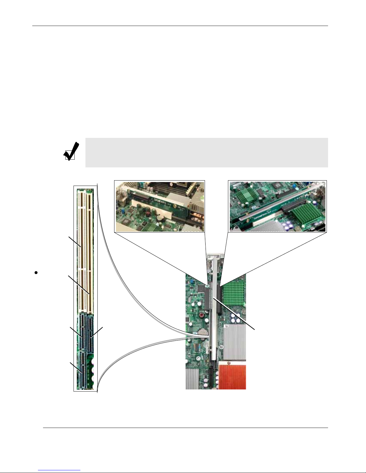
RES-12DCX Installation Manual
2.1.4 PCI Cards
Since the RES-12DCX is only 1RU (1.75”) high, PCI cards must be installed horizontally
through one of the two PCI Riser Cards (see Figure 2-5, Figure 2-6 and Figure 2-7 on
page 2-9, and Figure 2-8 on page 2-10), one PCI card for each. Configurations include:
•Two PCI-Express (x8) cards
• Two PCI-X cards, one 133 MHz (Slot 6) and one 100 MHz, ZCR (Slot 7)
•One PCI-Express (x8) card and one 100-MHz, 64-bit (Slot 7) or one 133-MHz,
64-bit (Slot 6) PCI-X card
Note: The PCI Riser Cards that are installed on the RES-12DCX motherboard
depend on the type of PCI card that will be supported.
Slot 6 Slot 7
PCI-X Slot (133 MHz)
PCI-X Slot (100 MHz)
ZCR Support
PCI-Express Slot (x8) PCI-Express Slot (x8)
PCI-Express Slot (x8)
PCI Slots (Top View)
PCI Slot-6 Riser Card PCI Slot-7 Riser Card
(see details on next page) (see details on next page)
PCI Riser-Card Retainer Bracket
RES-12DCX Motherboard (Partial Top View)
Figure 2-5. Positioning of the RES-12DCX PCI Riser Cards
2-8
Themis Computer
Page 55
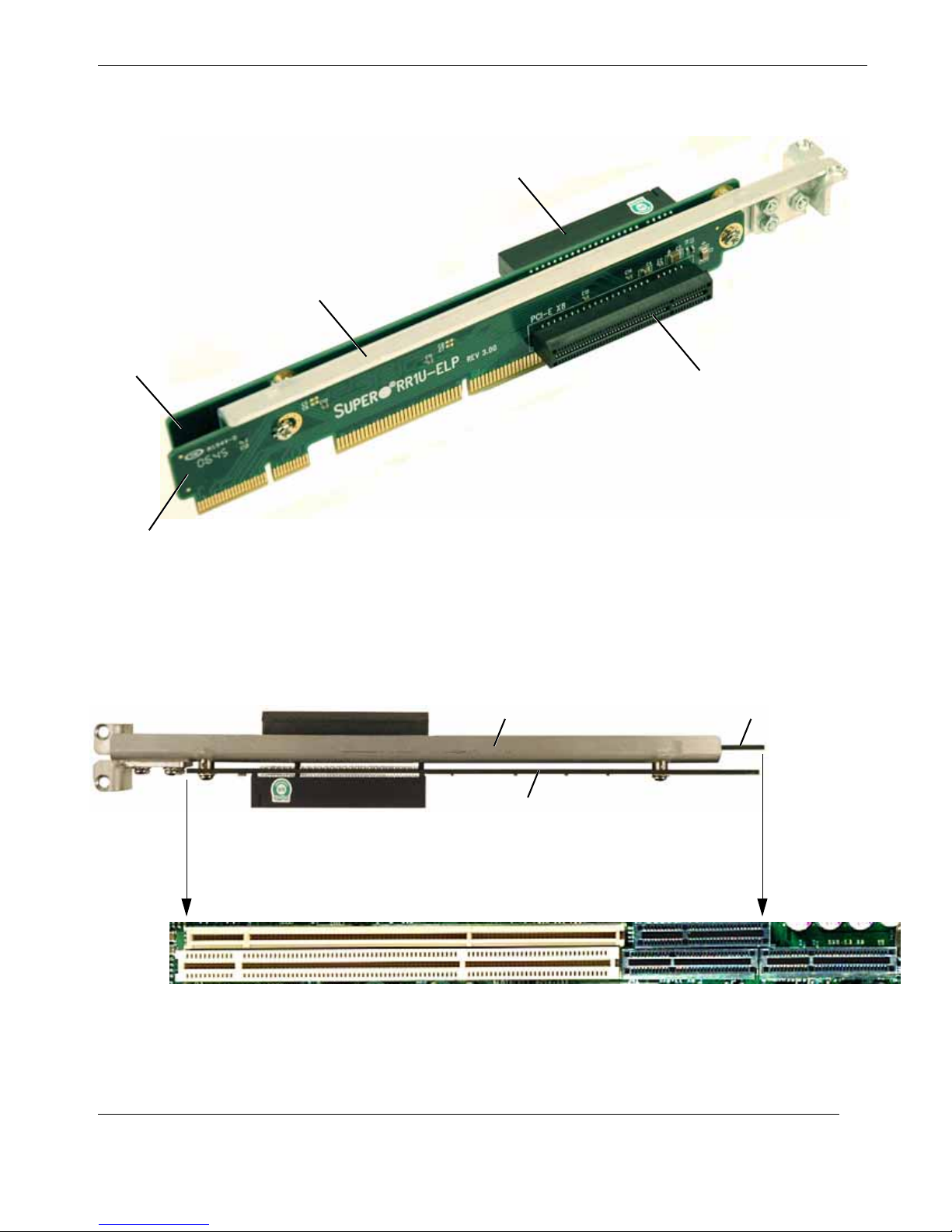
Slot 6 Riser Card
Installation and Operation
Installation Procedures
PCI Card Slot
Retainer Bracket
PCI Card Slot
Slot 7Riser Card
Figure 2-6. PCI Riser Cards are attached to a Retainer Bracket . . .
Top View of Retainer Bracket with Riser Cards attached
A
Slot 7
Slot 6
Retainer Bracket
Slot 6 Riser Card
Slot 7 Riser Card
Figure 2-7. . . . then inserted into Slots 6 and 7 of the Motherboard
Themis Computer
Top View of PCI Slot 6 and Slot 7 on Motherboard
B
2-9
Page 56
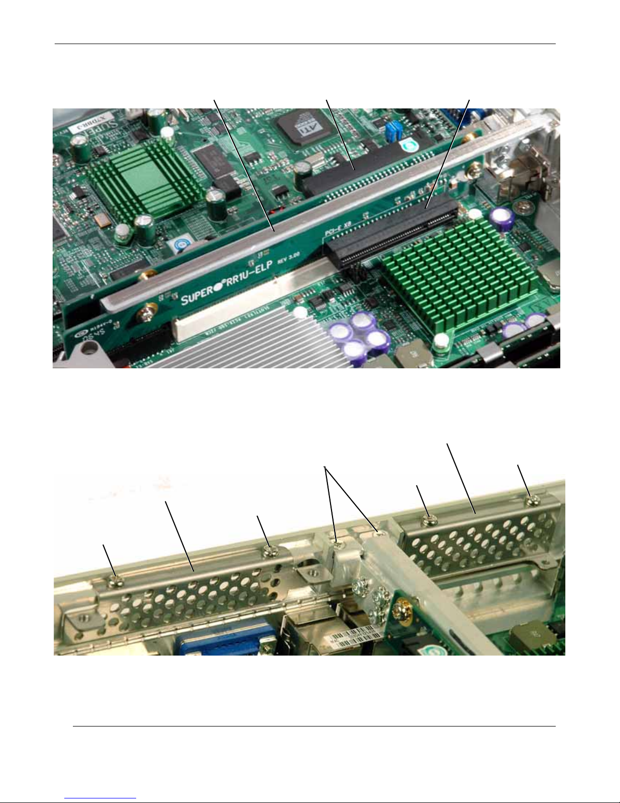
RES-12DCX Installation Manual
PCI Card Slot (Slot 7)PCI Card Slot (Slot 6)PCI Riser-Card Retainer Bracket
PCI Riser-Card Retainer Bracket Mounting Screws
Blank PCI-Card Panel (Slot 6)
Panel Screw
Figure 2-8. PCI Riser Cards Installed in Slot 6 and Slot 7
Blank PCI-Card Panel (Slot 7)
Panel Screw
Panel Screw
Panel Screw
Figure 2-9. Remove the Blank Panel for each PCI Card to be Installed
2-10
Themis Computer
Page 57

Note: When your RES-12DCX system is shipped, the both PCI Riser Cards and
any PCI cards you have ordered will already be installed.
2.1.4.1 Installation
Follow these steps to install a PCI card in the RES-12DCX system:
1. Remove the two Phillips screws holding each blank PCI-card panel to the
chassis. Place each blank panel and its two screws in a safe place.
2. Make sure that the two screws holding the PCI Riser-Card retainer bracket to
the chassis are firmly tightened (see Figure 2-9 on page 2-10), and that each
PCI Riser Card is firmly seated in its respective slot on the motherboard (see
Figure 2-5 through Figure 2-8).
Installation and Operation
Installation Procedures
3. Install a PCI card in an available slot on the Riser Card, securing its I/O face-
plate to the rear of the chassis with the Phillips screws removed in Step 1.
4. If necessary, install a second PCI card in the second available slot, securing
its I/O faceplate to the rear of the chassis with the Phillips screws removed in
Step 1.
5. Attach any internal I/O cables to the installed PCI cards.
6. Carefully fold and tuck any exposed ribbon cables into the chassis.
7. If you have no further internal installations to perform, close the RES-12DCX
chassis by refastening the top cover removed in Step 1 on page 2-2.
Themis Computer
2-11
Page 58
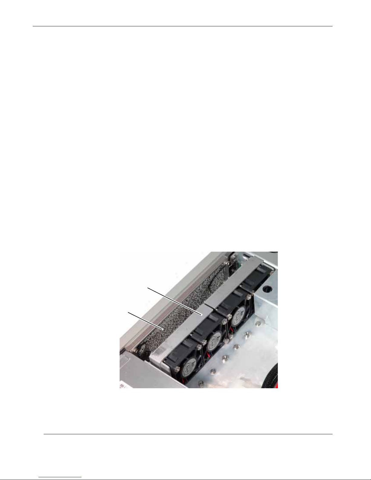
RES-12DCX Installation Manual
2.1.5 Removable 38-mm Fan Housing
The RES-12DCX contains a single fan housing at the front of the system with four
high-speed 38-mm fans (see Figure 2-10). The fan housing is removable in the field
for replacement in the event of a fan failure.
2.1.5.1 Removing the 38-mm Fan Housing
Perform the following steps to remove a 38-mm Fan Housing:
1. Make sure the system is powered off (see “Operation” on page 2-16).
2. With a Phillips screwdriver, loosen the two screws holding the 38-mm qua-
druple-fan housing to the RES-12DCX chassis (see Figure 2-11, page 2-13)
until the housing is released.
3. Six twisted wires (three pairs) form the cabling system of the fan housing.
Carefully remove the 3-pin fan-cable connector from its counterpart connector on the motherboard. Remember where the cable was attached for later reconnection.
4. The 38-mm fan housing can now be removed from the RES-12DCX chassis.
Place the fan housing and its two Phillips screws in a safe place.
Fan Housing Containing
Four 38-mm Fans
Washable Air Filter
Figure 2-10. The RES-12DCX 38-mm Quadruple-Fan Housing
2-12
Themis Computer
Page 59
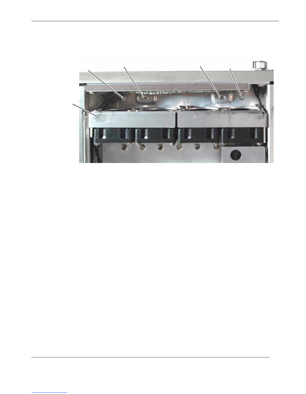
Installation and Operation
Installation Procedures
Fan-Housing Key
38-mm Fan Housing
Phillips Screw
Figure 2-11. Release the Two Screws Securing the 38-mm Fan Housing
2.1.5.2 Installing a 38-mm Fan Housing
Phillips Screw
Fan-Housing Key
Perform the following steps to install a 38-mm fan housing:
1. Insert the replacement 38-mm fan housing into the position formerly occupied
by the removed housing, aligning the two holes at the bottom of the new fan
housing with the alignment keys at the bottom of the chassis (see Figure
2-11).
2. Connect the 3-pin fan cable connector from the new 38-mm fan housing to the
original connectors from which the replaced fan-housing cables were removed. The cable connector is keyed to prevent incorrect cable insertion.
3. Reinsert and tighten the two screws at the bottom of the fan housing with a
Phillips screwdriver until the fan housing is firmly secured to the chassis.
Themis Computer
2-13
Page 60
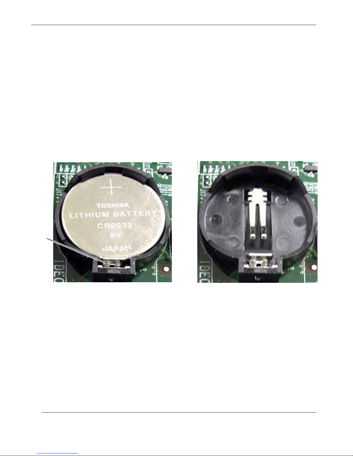
RES-12DCX Installation Manual
2.1.6 Lithium Battery
2.1.6.1 Removing the Lithium Battery
Perform the following steps to remove the lithium battery:
1. Make sure the system is powered off (see “Operation” on page 2-16).
2. Locate the lithium battery socket (see Figure 1-4, page 1-6) and squeeze the
latch (see A, Figure 2-12) together until the battery lifts out of its socket.
3. Remove the old battery and replace with a new battery (see next section).
Battery
Latch
AB
To release, squeeze the battery latch together . . .
Figure 2-12. The RES-12DCX Lithium Battery and Socket
. . . and remove the battery from its socket
2.1.6.2 Installing a Lithium Battery
Perform the following steps to insert a new lithium battery:
1. Tilt the replacement battery into the empty socket so that it is angled under the
battery latch ((see B, Figure 2-12).
2. Carefully press down on the battery until it clicks firmly into place.
2-14
Themis Computer
Page 61
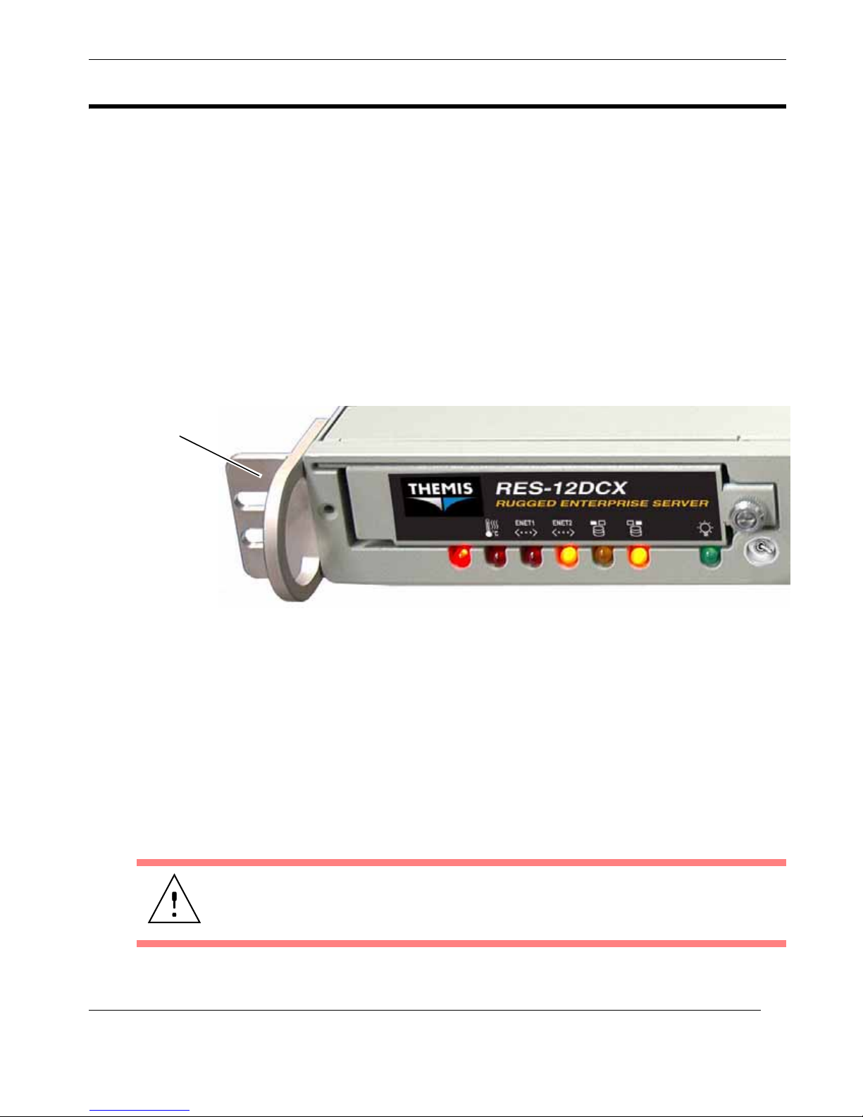
2.2 Rack Mounts
2.2.1 Mounting Brackets
A pair of rack-mount brackets (flanges) with handles is shipped with the RES12DCX to secure the chassis to a 19” rack (see Figure 2-13). The chassis contains
three threaded screw holes on each side to accommodate #10-32 size screws
(included with the bracket package).
Brackets with handles are used to pull the RES-12DCX from the rack when rackmount slides have been installed on the sides of the chassis (see following section).
Left Rack-Mount Bracket
Installation and Operation
Rack Mounts
Figure 2-13. Left Rack-Mount Bracket with a Handle
2.2.2 Rack-Mount Slides (Optional)
Rack-Mount Slides can be mounted on each side of the RES-12DCX for the purpose
of sliding the unit in and out of a rack. Mounting slides are optional and should be
ordered at the time your system is purchased.
To learn how to install rack-mount slides, refer to Appendix B, “Rack-Mount Slide
Installation”.
Caution: Any screws used to mount a slide to a RES-12DCX chassis must not exceed a length of 3/8” to prevent excessive penetration of the chassis.
Themis Computer
2-15
Page 62
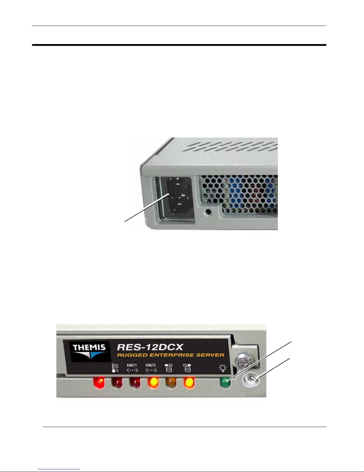
RES-12DCX Installation Manual
2.3 Operation
2.3.1 Plugging in the AC Power Cord
Before powering on the RES-12DCX, plug in the AC power cord as follows:
1. On the rear of the RES-12DCX chassis, plug an AC power cord (shipped with
each unit) into the AC power socket on the power supply (see Figure 2-14).
AC Power Socket
Figure 2-14. AC Power Socket on the Rear of the RES-12DCX
2.3.2 Turning the System On
1. Plug the AC power cord already attached to the RES-12DCX power supply
into a “live” AC outlet.
2. Push the system power on/off switch on the front of the RES-12DCX (see
Figure 2-15). This will cause the system POWER LED to light (green).
System Power LED
System Power Switch
Figure 2-15. System Power Switch and LED on the Front of the RES-12DCX
2-16
Themis Computer
Page 63
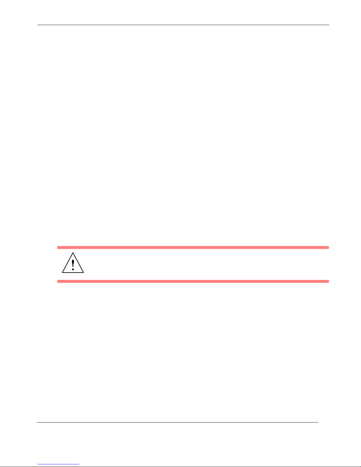
2.3.3 Getting Started
2.3.3.1 Configuration
1. Make sure all SATA-II drives are installed (see “SATA-II Hard-Disk Drive”
on page 2-6).
2. Make sure that a graphics card (x8 PCI-Express) is installed in one of the Ris-
er Card PCI slots (refer to Section 2.1.4, “PCI Cards,” on page 2-8), then connect a multiscan monitor to the SVGA or DVI connector.
3. Attach a PS/2 keyboard and mouse to the appropriate connectors on the rear
I/O panel of the RES-12DCX (see Figure 1-3 on page 1-3)
4. Turn the system on (see previous section).
2.3.3.2 Linux Installation
Installation and Operation
Operation
The subject of installing the Linux operating system onto the RES-12DCX is
detailed in Appendix D, “Red Hat Enterprise Linux Installation”.
2.3.4 Turning the System Off
Caution: Before turning your system off, make sure to save all open files, properly
close applications, and broadcast a warning to all users on any active networks.
1. To turn the RES-12DCX power off, press and hold the system power on/off
button (see Figure 2-15) for at least four (4) seconds. This will shut down the
system and turn off the POWER LED.
As an alternative, a modern operating system (Windows 9x or newer and
Linux, for example) can turn off the system after a graceful OS software
shutdown.
Themis Computer
2-17
Page 64

RES-12DCX Installation Manual
2-18
Themis Computer
Page 65
A
Appendix
Connector Pinouts
This appendix provides connector pinouts and signal descriptions for the user I/O
connectors that are installed on the RES-12DCX rear I/O Panel (see Figure 1-3,
page 1-3).
A.1 PS/2 Keyboard and Mouse
The RES-12DCX rear I/O Panel provides a 6-pin female mini-DIN connector for the
PS/2 keyboard, and another for the PS/2 mouse.
A pinout and signal descriptions for both connectors are defined in Table A-1.
Table A-1. PS/2 Keyboard/Mouse Connector Pinout and Signal Descriptions
Pin Signal Description
1 Keyboard/Mouse data
2 N/C
3Ground
4Vcc
5 Keyboard/Mouse clock
6 N/C
3
JKB / JMS
5
1
6
4
2
Themis Computer
A-1
Page 66
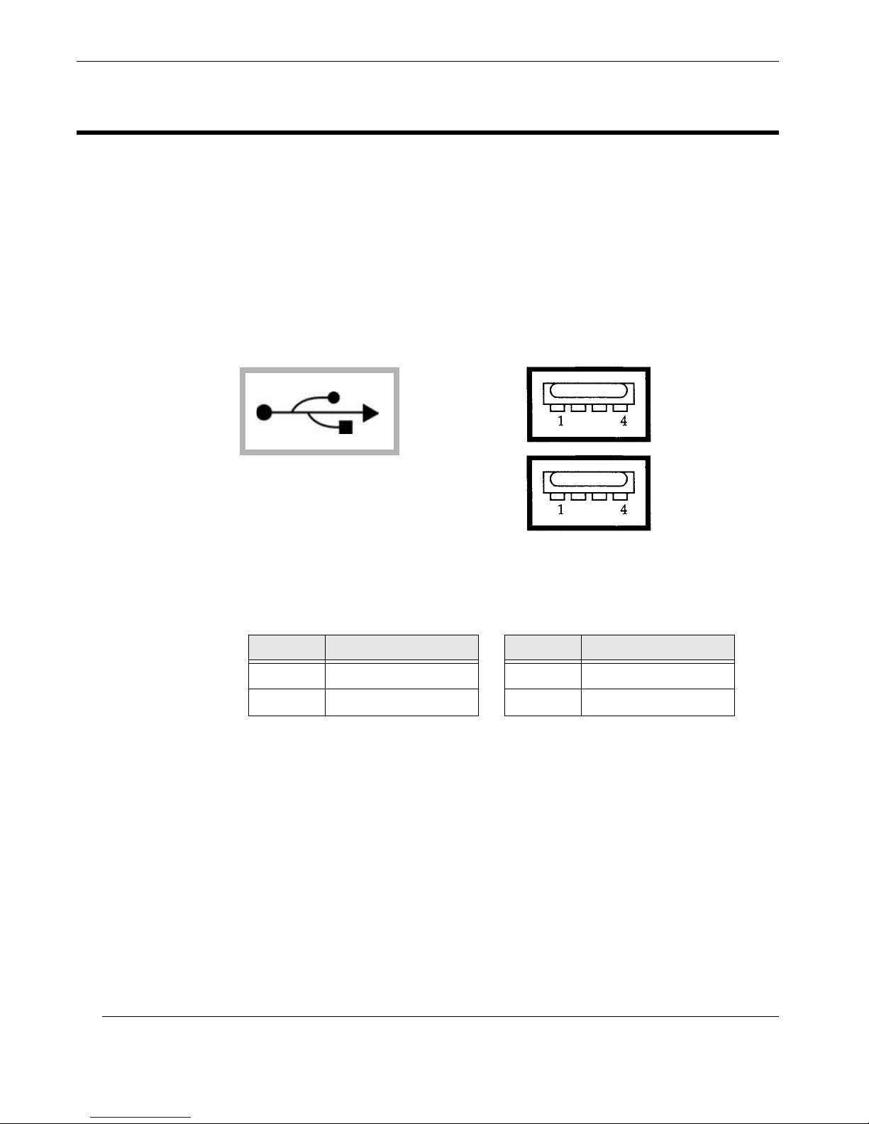
RES-12DCX Installation Manual
A.2 USB Port
The RES-12DCX supports two USB (Universal Serial Bus) port connectors—USB 0
(A) and USB 1 (B)—on the rear I/O Panel (see Figure A-1 for connector pinouts);
four optional USB ports (USB 2, 3, 4, and 5), accessed from on-board motherboard
headers, are not supported by the RES-12DCX.
Pinout signal descriptions are listed in Table A-2.
Symbol
USB 1 (Port B)
USB 0 (Port A)
USB Ports
JUSB1
Figure A-1. USB Ports A and B Connector Pinout
Table A-2. USB Connector Pinout Signal Descriptions
Pin Signal Name Pin Signal Name
1+5V 3PO+
2PO– 4GND
A-2
Themis Computer
Page 67
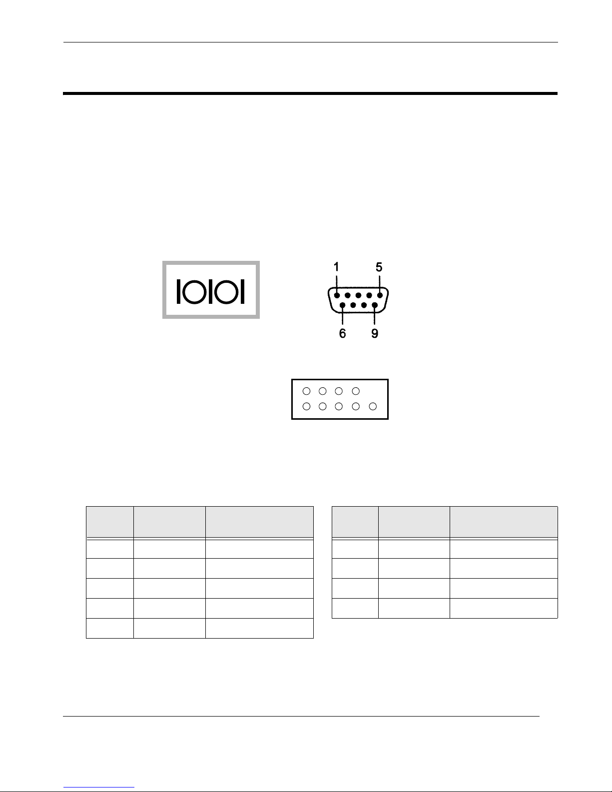
A.3 Serial Port
The RES-12DCX supports one male DB9 serial port connector on the rear I/O Panel
(see Figure A-2)—COM 1 (TTYA)—and a second—COM 2 (TTYB)—directly
from a header on the motherboard.
COM 1 and COM 2 connector-pin signals are described in Table A-3.
Symbol
Connector Pinouts
Serial Port
COM 1
JCOM1 (Rear I/O Panel)
6789
COM 2
JCOM2 Header (Motherboard)
12345
Figure A-2. COM 1/COM 2 Serial Port Connector Pinout
Table A-3.
Pin
1 DCD Data Carrier Detect 6 DSR Data Set Ready
2 RXD Receive Data 7 RTS Request To Send
3 TXD Transmit Data 8 CTS Clear To Send
4 DTR Data Terminal Ready 9 RI Ring Indicator
5 GND Signal Ground
Signal
Name
COM 1/COM 2 Serial Port Pinout Signal Descriptions
Signal Definition Pin
Signal
Name
Signal Definition
Themis Computer
A-3
Page 68
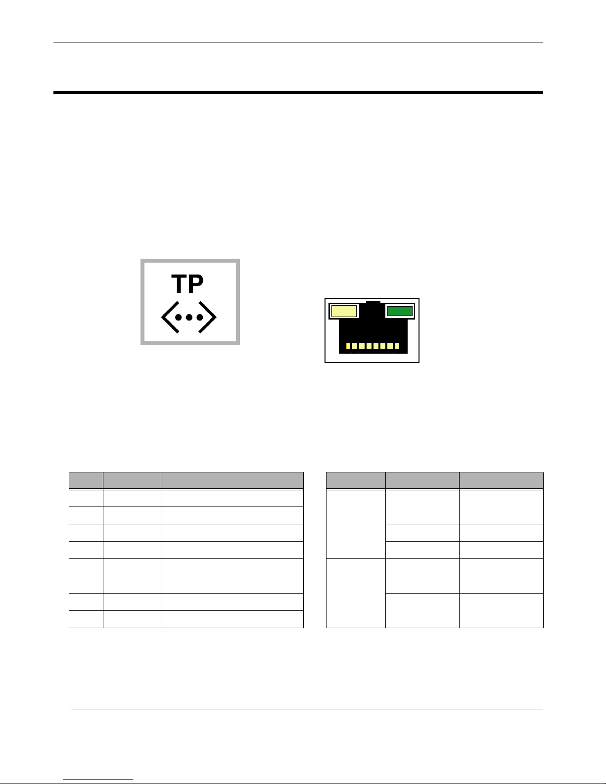
RES-12DCX Installation Manual
A.4 Gigabit Ethernet LAN Port
The RES-12DCX supports two RJ45 Gigabit Ethernet port connectors—LAN 1 and
LAN 2 (see Figure A-3 for a connector pinout). Both LAN 1 and LAN 2 have two
status LED indicators, one (on the left) for link speed and one (on the right) for network activity.
Pinout signal descriptions and LED interpretations are given in Table A-4.
Symbol
Link LED Activity LED
8
1
Figure A-3. LAN 1/LAN 2 Gigabit Ethernet Connector Pinout
Table A-4. Gigabit Ethernet Connector Pinout Signals and LED Interpretation
Pin Signal Description LED LED Color
1 TRD0+ Transm it/R eceive Data 0 +
2 TRD0- Transmit/Receive Data 0 –
3 TRD1+ Transm it/Receive Data 1 + Green 100 Mb/s
4 TRD2+ Transm it/Receive Data 2 + Amber 1 Gb/s
5 TRD2- Transmit/Receive Data 2 –
6 TRD1- Transmit/Receive Data 1 –
7 TRD3+ Transm it/R eceive Data 3 +
8 TRD3- Transmit/Receive Data 3 –
Amber/
Green
(Left)
= Link
Speed
Green
(Right)
= Network
Activity
OFF
OFF No Activity
Blinking Active
a
Interpretation
No Connection
or 10 Mb/s
A-4
Themis Computer
Page 69
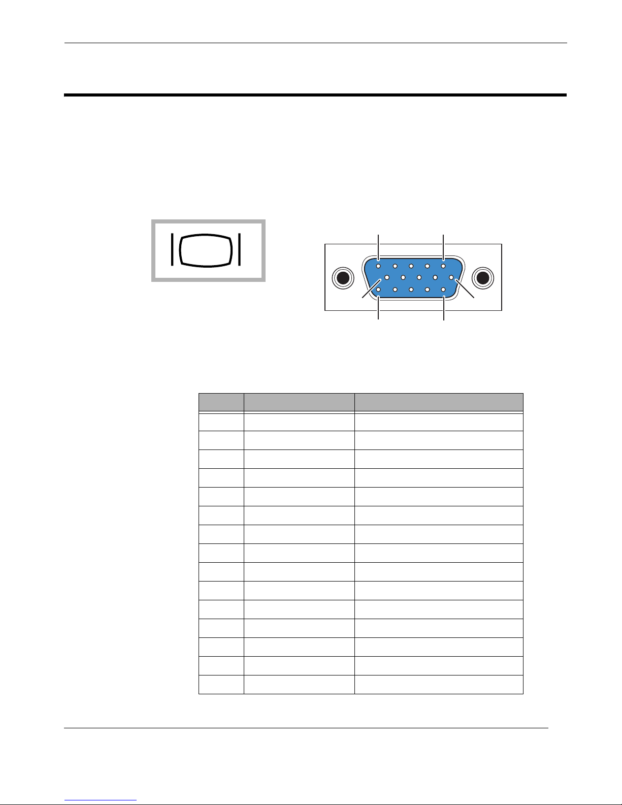
A.5 VGA Display Port
6
10
15 11
15
The RES-12DCX supports a single 15-pin (three 5-pin rows) female VGA graphics
display port connector on the rear I/O Panel (see Figure A-4 for a connector pinout).
Pinout signal descriptions are listed in Table A-5.
Connector Pinouts
VGA Display Port
Symbol
VGA Display Port
Figure A-4. VGA Connector Pinout
Table A-5. VGA Connector Pinout Signal Descriptions
Pin Signal Description
1 RED Red video
2 GREEN Green video
3 BLUE Blue video
4 ID2 Monitor ID bit 2
5 GND Ground (HSync)
JVGA1
Themis Computer
6 RED_RTN Red return
7 GREEN_RTN Green return
8 BLUE_RTN Blue return
9 KEY Key (no pin)
10 GND Ground (VSync)
11 ID0 Monitor ID bit 0
12 ID1 or SDA Monitor ID bit 1
13 HSYNC Horizontal sync
14 VSYNC Vertical sync
15 ID3 or SCL Monitor ID bit 3
A-5
Page 70
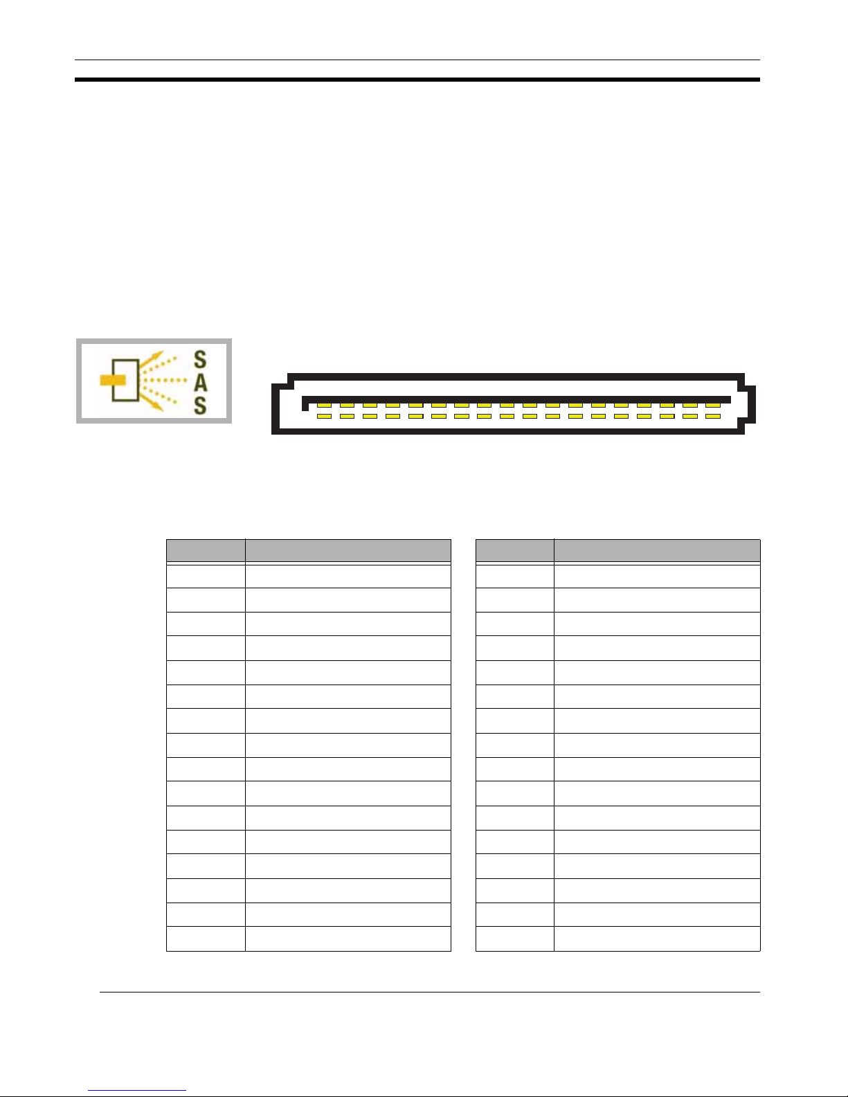
RES-12DCX Installation Manual
A18A1
B18B1
A.6 SAS Port
The RES-12DCX supports eight Serial-Attached SCSI (SAS) ports, four of which
are accessed through the rear I/O Panel (SAS 4 through SAS 7; see Figure A-5 for a
pinout). The remaining four SAS ports (SAS 0 through SAS 3) are accessed from the
surface of the motherboard. SAS pinout signal descriptions are given in Table A-6.
In addition, the surface of the RES-12DCX motherboard has 16 LED status indicators associated with the SAS ports—eight LEDs to indicate the presence of an SAS
connector and eight LEDs to indicate SAS activity (see Figure A-6 on page A-7).
Symbol
SAS Ports 4 - 7
JSM2
Figure A-5. SAS Connector Pinout
Table A-6. SAS Connector Pinout Signal Descriptions
Pin Signal Pin Signal
A1 GROUND B1 GROUND
A2 RX 0+ B2 TX 0+
A3 RX 0– B3 TX 0–
A4 GROUND B4 GROUND
A5 RX 1+ B5 TX 1+
A6 RX 1– B6 TX 1–
A7 GROUND B7 GROUND
A8 SB7 B8 SB0
A9 SB3 B9 SB1
A10 SB4 B10 SB2
A11 SB5 B11 SB6
A12 GROUND B12 GROUND
A13 RX 2+ B13 TX 2+
A14 RX 2– B14 TX 2–
A15 GROUND B15 GROUND
A16 RX 3+ B16 TX 3+
A-6
Themis Computer
Page 71
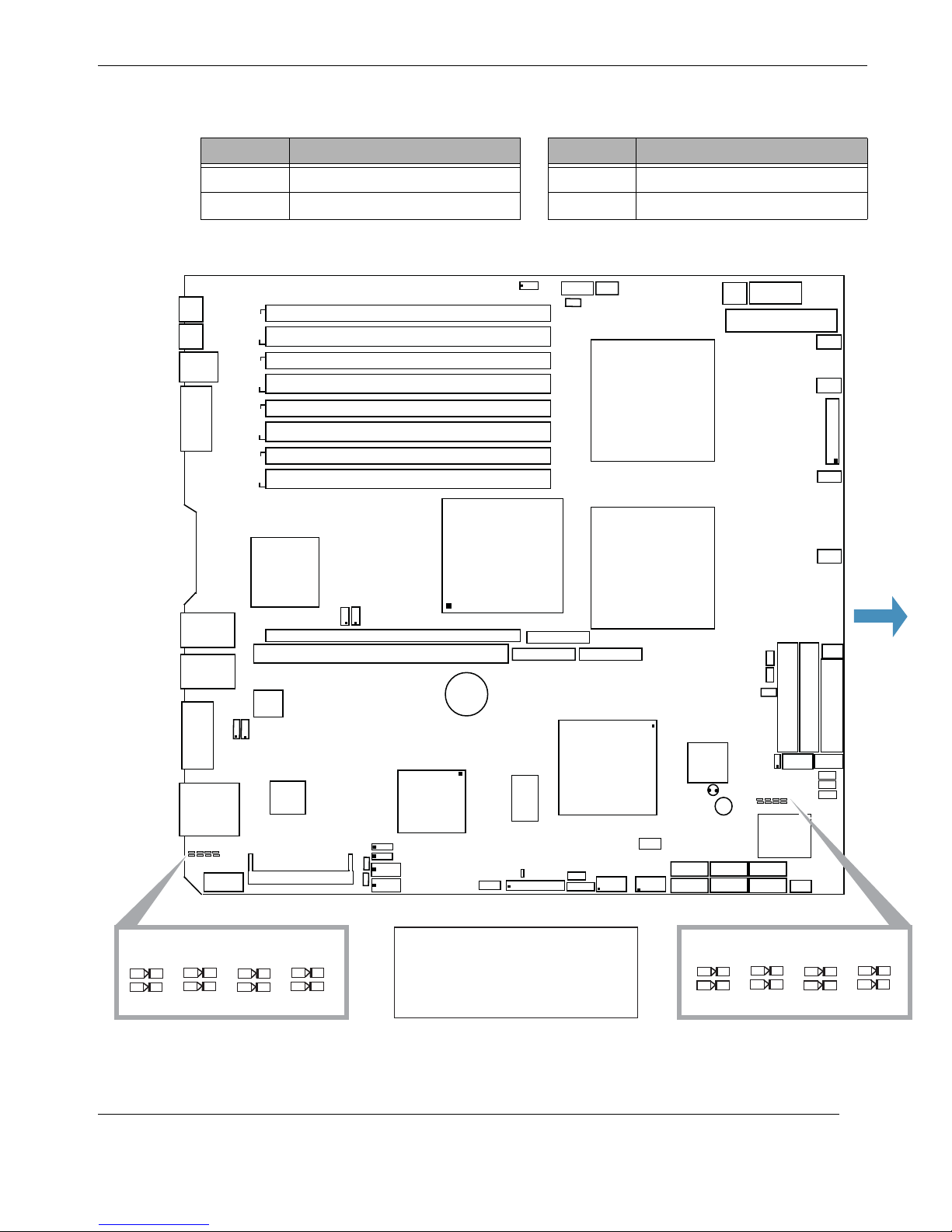
Table A-6. SAS Connector Pinout Signal Descriptions (Continued)
Pin Signal Pin Signal
A17 RX 3– B17 TX 3–
A18 GROUND B18 GROUND
Connector Pinouts
SAS Port
Keyboard
Mouse
USB 0/1
Serial Port 1
GbE LAN 1
GbE LAN 2
VGA Port
SAS Ports 4-7
KB
JKB
MS
JMS
USB0/1
JUSB1
COM1
JCOM1
GLAN1
GLAN2
AGV
JVGA1
7-4SAS
Pre#4-7
Act#4-7
JLAN1
JLAN2
JSM2
COM2
JCOM2
1LPJ
4knaB
3knaB
2knaB
1knaB
Slot6
GLAN
CTRLR
2LPJ
J9B2
J9B1
J8B3
J8B2
J8B1
J7B3
J7B2
J7B1
DIMM 4B
DIMM
4A
DIMM 3B
DIMM
3A
DIMM 2B
DIMM
2A
DIMM 1B
DIMM
1A
North Bridge
PXH-V
C2
C1
2
2
JI
Slot7
VGA
CTRLR
SIMS
O
JI
PCI-X 100MHz ZCR S XB -
PCI-X 133MHz
Battery
SAS
CTRLR
JPG1
01PJ
JPS1
SMB
J18
11PJ
JIPMI
IPMB
J10
3rd PWR
Fail
J13
JWOR
WOR
PWR
J3P
SMB
E1x8
E2x8
SXB-
O/IS
LE1
JD1
PWLEDSPK
SAS Ports 4 - 7
J17
JPWF
JAR
J41
E3x8
J42
SXB-
J43
South
Bridge
USB4/5
J8
JUSB3
J4E3
CPU1
CPU2
WOL
JWOL
USB2/3
JUSB2
JBT1
SATA1
JS2
SATA0
JS1
4-pin
PWR
BIOS
8-pin PWR
JPW2
20-pin ATXMain PWR
JWF1
Pre#0-3
Act#0-3
Buzzer
SATA3
SATA5
JS4
SATA2
SATA4
JS3
DWJ
1FCJ
JS6
JS5
JPW3
SGPIO2
JP12
3-1SAS
alF
tcapmoChs
2EDIJ
J30
JOH1
JSM1
JS10
JPW1
Fan1
Fan2
Fan3
Fan4
Fan5
1EDI
1ED
IJ
J22
SGPIO1
J7
JL1
JF1
rtCPFl
Front
yppolF
J29
SAS 4 SAS 5
Pre #4
Act #4
Pre #5 Pre #6
Act #5
SAS 6 SAS 7 SAS 0 SAS 1 SAS 2 SAS 3
Pre #7
Act #6
Act #7
Status LEDs - SAS 4 to SAS 7 Status LEDs - SAS 0 to SAS 3
Themis Computer
Note:
Pre = Indicates the Presence of the
Pre #0
numbered SAS connector
Act = Indicates the Activity status of
the numbered SAS connector
Act #0
Figure A-6. SAS Status LEDs on Motherboard
Pre #1 Pre #2 Pre #3
Act #1
Act #2
Act #3
A-7
Page 72

RES-12DCX Installation Manual
A-8
Themis Computer
Page 73
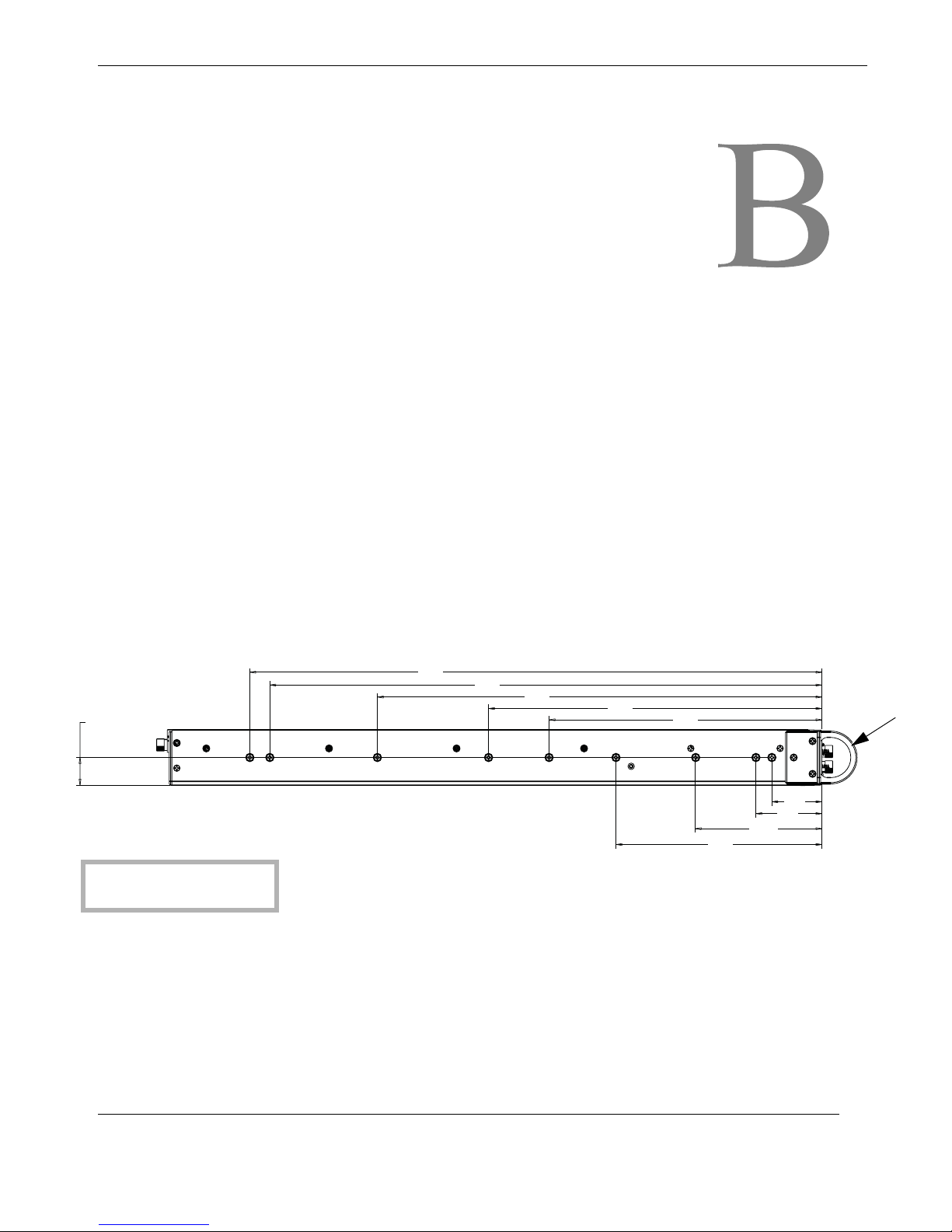
B
Appendix
Rack-Mount Slide Installation
An optional set of two rack-mount slides (left side and right side) is available for all
RES-12 systems, and should be ordered at the time of purchase. The RES-12DCX
chassis contains nine threaded screw holes (see Figure B-1) on each side to accommodate #8-32 size screws (included with the rack-mount slide kit). Remember that
steel slides and aluminum slides may require different mounting holes and may also
share one or more mounting holes.
22
Screw Hole Size
All holes = #8-32
Themis Computer
455.8
Note: All dimensions are given in millimeters (mm).
(See Figure B-2 on page B-3 for an exploded view.)
Figure B-1.
Dimensions of the screw-hole patterns on the sides of the RES-12DCX chassis for
installing rack-mount slides are shown in Figure B-1. The required holes for a specific steel or aluminum slide will have to be measured before installation.
439.9
354.2
265.6
217.4
164.1
Screw Locations for Rack-Mount Slides
100.95
52.6
Mounting
Bracket
39.9
B-1
Page 74

RES-12DCX Installation Manual
Caution: Any screws used to mount a slide to a RES-22 chassis must not exceed a
length of 3/8” to prevent excessive penetration of the chassis.
The rack-mount slide installation kit includes the following items:
a. Two inside slide sections
b. Two outside slide sections
c. Two front (short) slide brackets
d. Two rear (long) slide brackets
e. Assorted screws, washers, and nuts
Follow these steps to install a steel rack-mount slide to the RES-12DCX chassis:
1. Attach the inside slide section (see Figure B-2 on page B-3) to both sides of
the RES-12DCX chassis using three or four #8-32 screws per side.
2. Measure the depth of the 19” equipment rack into which the RES-12DCX sys-
tem will be installed (this can vary from 24” to 30”).
3. Using the depth of the equipment rack, adjust and attach the front and rear
slide brackets to the outside slide section using the screws, washers, and nuts
provided with the slide kit.
4. With all slide brackets securely attached to both the right and left outside slide
sections, install both sections to the inside right and inside left of a 19” rack
with two bolts per bracket, making sure there is adequate room for the 1RU
height (1.75”) of a RES-12DCX system.
5. Carefully insert the RES-12DCX system into the 19” rack so that the inside
slides on both sides of the chassis travel smoothly into the channels of the outside slide sections. Push the system into the rack until the mounting brackets
on the front of the chassis are flush with the front of the rack.
6. Secure the RES-12DCX system to the 19” rack with two bolts on each side.
B-2
Themis Computer
Page 75
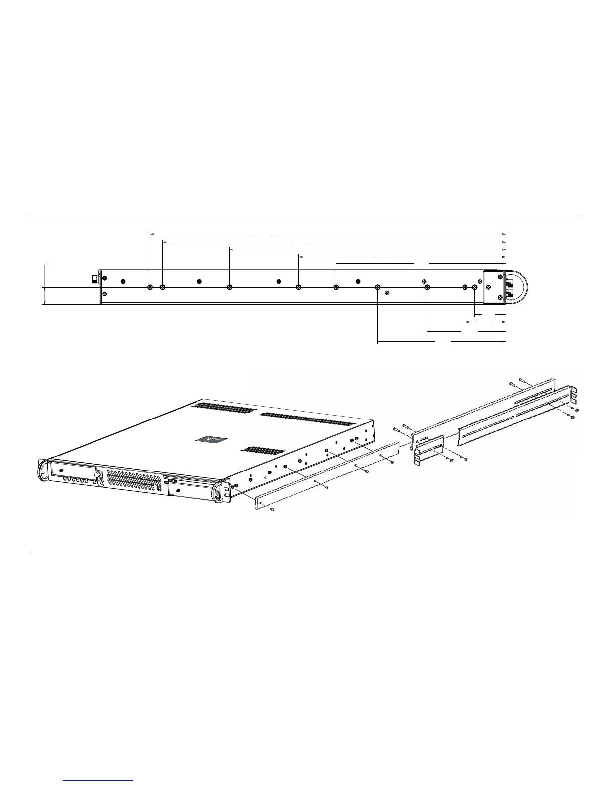
Themis Computer
Rack-Mount Slide Installation
B-3
B
Figure B-2. RES-12DCX Rack-Mount Slide Installation
455.8
Note: All dimensions are given in millimeters (mm).
439.9
354.2
265.6
217.4
52.6
39.9
164.1
100.95
22
A Side View of RES-12DCX Slide Installation
B RES-12DCX Rack-Mount Slide Installation
Page 76

Themis Computer
RES-12DCX Installation Manual
B-4
Page 77
C
C.1 Introduction
This chapter describes the Phoenix BIOS™ Setup utility for the RES-12DCX. The
Phoenix ROM BIOS is stored in a flash chip and can be easily upgraded using a
floppy-disk-based program.
Appendix
BIOS Setup Utility
Note: Due to periodic changes to the BIOS, some settings may have been added
or Deleted and might not yet be recorded in this manual. Please refer to the
Manual Download area of the SuperMicro web site http://www.supermicro.com
for any changes to the BIOS that may not be reflected in this manual.
C.1.1 System BIOS
The BIOS is the Basic Input Output System used in all IBM® PC, XT™, AT®, and
PS/2® compatible computers. The Phoenix BIOS stores the system parameters,
types of disk drives, video displays, etc. in the CMOS. The CMOS memory requires
very little electrical power. When the computer is turned off, a backup battery provides power to the CMOS logic, enabling it to retain system parameters. Each time
the computer is powered on the computer is configured with the values stored in the
CMOS logic by the system BIOS, which gains control at boot up.
Themis Computer
C-1
Page 78
RES-12DCX Installation Manual
C.1.2 How To Change the Configuration Data
The CMOS information that determines the system parameters may be changed by
entering the BIOS Setup utility. This Setup utility can be accessed by pressing the
<Delete> key at the appropriate time during system boot. (See following Section.)
C.1.3 Starting the Setup Utility
Normally, the only visible POST (Power On Self Test) routine is the memory test.
As the memory is being tested, press the <Delete> key to enter the main menu of
the BIOS Setup utility. From the main menu, you can access the other setup screens,
such as the Security and Power menus. Beginning with Section 4-3, detailed descriptions are given for each parameter setting in the Setup utility.
Warning: To prevent possible boot failure, do not shut down or reset the system
while updating the BIOS.
C.2 Running Setup
Note: Default settings are shown in bold text unless otherwise noted.
The BIOS setup options described in this section are selected by choosing the appropriate text from the main BIOS Setup screen (see Figure C-1 on page C-3). The
screen display is often all you need to understand how to set the options.
When the computer is first powered on, the Phoenix BIOS™ is immediately activated. While the BIOS is in control, the Setup program can be activated in one of
two ways:
1. By pressing <Delete> immediately after turning the system on, or
2. When the message shown below appears briefly at the bottom of the screen
during the POST (Power On Self-Test), press the <Delete> key to activate
the main Setup menu:
Press the <Delete> key to enter Setup
C-2
Themis Computer
Page 79
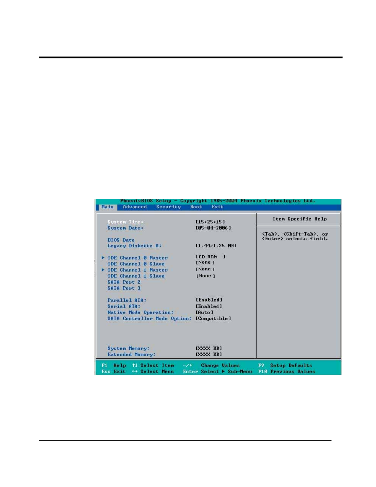
C.3 Main BIOS Setup
All the main Setup options are described in this section. The main BIOS Setup
screen is displayed in Figure C-1.
Use the Up/Down arrow keys to move among the different settings in each menu.
Use the Left/Right arrow keys to change the options for each setting.
The icon X indicates a submenu. With the item highlighted, press the <Enter> key
to access the submenu.
Press the <Esc> key to exit the CMOS Setup Menu. The next section describes in
detail how to navigate through the menus.
BIOS Setup Utility
Main BIOS Setup
Themis Computer
Figure C-1. The Main BIOS Setup Menu
C-3
Page 80

RES-12DCX Installation Manual
C.3.1 Main Setup Features
C.3.1.1 System Time
To set the system date and time, key in the correct information in the appropriate
fields. Then press the <Enter> key to save the data.
C.3.1.2 System Date
Using the arrow keys, highlight the month, day, and year fields, and enter the correct
data. Press the <Enter> key to save the data.
C.3.1.3 BIOS Date
The item displays the date that the BIOS was built.
C.3.1.4 Legacy Diskette A
This setting allows the user to set the type of floppy disk drive installed as diskette
A. The options are: Disabled, 360Kb 5.25 in, 1.2MB 5.25 in, 720Kb 3.5 in,
1.44/1.25MB, 3.5 in and 2.88MB 3.5 in.
C.3.1.5 IDE Channel 0 Master/Slave, IDE Channel 1 Master/Slave, SATA
Port 2, and SATA Port 3
These settings allow the user to set the parameters of IDE Channel 0 Master/ Slave,
IDE Channel 1 Master/Slave, IDE Channel 2 Master, IDE Channel 3 Master slots.
Hit <Enter> to activate the following sub-menu screen for detailed options of these
items. Set the correct configurations accordingly. The items included in the submenu are:
Type
This option allows the user to selects the type of IDE hard drive. The option Auto
will allow the BIOS to automatically configure the parameters of the HDD installed
at the connection. Enter a number between 1 to 39 to select a predetermined HDD
type. Select User to allow the user to enter the parameters of the HDD installed.
Select CDROM if a CDROM drive is installed. Select ATAPI if a removable disk
drive is installed.
C-4
Themis Computer
Page 81

BIOS Setup Utility
Main BIOS Setup
Multi-Sector Transfer
This item allows the user to specify the number of sectors per block to be used in
multi-sector transfer. The options are Disabled, 4 Sectors, 8 Sectors, and 16 Sectors.
LBA Mode Control
This item determines whether the Phoenix BIOS will access the IDE Channel 0 Master Device via the LBA mode. The options are Enabled and Disabled.
32 Bit I/O
This option allows the user to enable or disable the function of 32-bit data transfer.The options are Enabled and Disabled.
Transfer Mode
This option allows the user to set the transfer mode. The options are Standard, Fast
PIO1, Fast PIO2, Fast PIO3, Fast PIO4, FPIO3/DMA1 and FPIO4/DMA2.
Ultra DMA Mode
This option allows the user to select Ultra DMA Mode. The options are Disabled,
Mode 0, Mode 1, Mode 2, Mode 3, Mode 4, and Mode 5.
C.3.1.6 Parallel ATA
This setting allows the user to enable or disable the function of Parallel ATA. The
options are Channel 0 and Channel 1.
C.3.1.7 Serial ATA
This setting allows the user to enable or disable the function of Serial ATA. The
options are Disabled and Enabled.
C.3.1.8 Native Mode Operation
Select the native mode for ATA. The options are Serial ATA, Both, and Auto.
C.3.1.9 SATA Controller Mode
Select Compatible to allow the SATA and PATA drives to be automaticallydetected and be placed in the Legacy Mode by the BIOS. Select Enhanced to allow
the SATA and PATA drives to be to be automatically-detected and be placed in the
Native IDE Mode
Themis Computer
C-5
Page 82
RES-12DCX Installation Manual
.
Note: The Enhanced mode is supported by the Windows 2000 OS or a later version.
When the SATA Controller Mode is set to “Enhanced”, the following will display:
Serial ATA (SATA) RAID Enable
Select Enable to enable Serial ATA RAID Functions.
Note: For the Windows OS environment, use the RAID driver if this
feature is set to Enabled. When this item is set to Enabled, the item:
“ICH RAID Code Base” will be available for you to select either Intel
or Adaptec Host RAID firmware to be activated. If this item is set to
Disabled, the item-SATA AHCI Enable will be available.)
The options are Enabled and Disabled.
ICH RAID Code Base
Select Intel to enable Intel's SATA RAID firmware. Select Adaptec to use Adaptec's
HostRAID firmware. The options are Intel and Adaptec.
SATA AHCI
Select Enable to enable the function of Serial ATA Advanced Host Interface.
Caution: This feature is for advanced programmers only. The options
are Enabled and Disabled.
C.3.1.10System Memory
This display informs you how much system memory is recognized as being present
in the system.
C.3.1.11Extended Memory
This display informs you how much extended memory is recognized as being
present in the system.
C-6
Themis Computer
Page 83
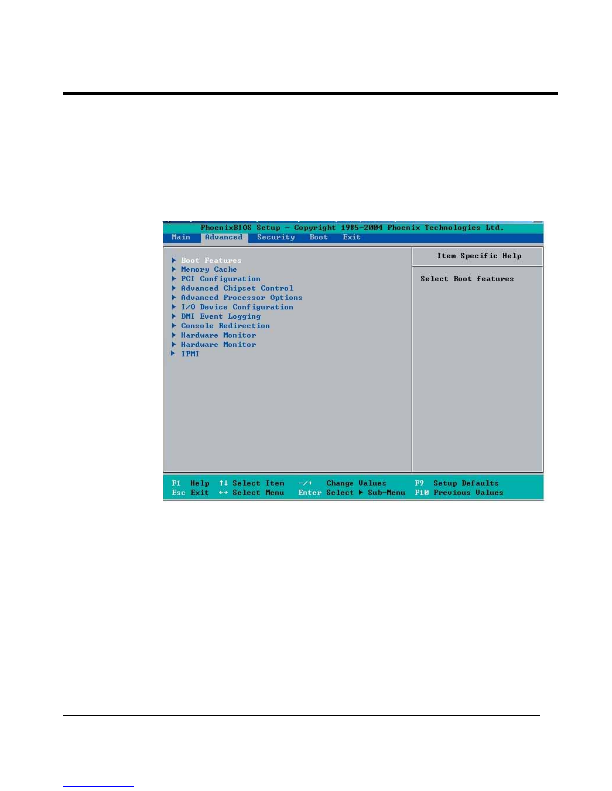
C.4 Advanced Setup
Choose Advanced from the Phoenix BIOS Setup Utility main menu with the arrow
keys. You should see the display shown in Figure C-2. The items with a triangle
beside them have submenus that can be accessed by highlighting the item and pressing <Enter>.
BIOS Setup Utility
Advanced Setup
C.4.1 X Boot Features
Access the Boot Features submenu to make changes to the following settings.
C.4.1.1 Quick Boot Mode
If enabled, this feature will speed up the POST (Power On Self Test) routine by skipping certain tests after the computer is turned on. The settings are Enabled and Disabled. If Disabled, the POST routine will run at normal speed.
Themis Computer
Figure C-2. The Advanced BIOS Setup Menu
C-7
Page 84

RES-12DCX Installation Manual
C.4.1.2 Quiet Boot Mode
This setting allows you to Enable or Disable the graphic logo screen during boot-up.
C.4.1.3 POST Errors
Set to Enabled to display POST Error Messages if an error occurs during bootup. If
set to Disabled, the system will continue to boot without displaying any error messages even when a boot error occurs.
C.4.1.4 ACPI Mode
Use the setting to determine if you want to employ ACPI (Advanced Configuration
and Power Interface) power management on your system. The options are Yes and
No.
C.4.1.5 Power Button Behavior
If set to Instant-Off, the system will power off immediately as soon as the user hits
the power button. If set to 4-sec., the system will power off when the user presses the
power button for 4 seconds or longer. The options are instant-off and 4-sec override.
C.4.1.6 Resume On Modem Ring
Select On to “wake your system up” when an incoming call is received by your
modem. The options are On and Off.
C.4.1.7 Power Loss Control
This setting allows you to choose how the system will react when power returns after
an unexpected loss of power. The options are Stay Off, Power On, and Last State.
C.4.1.8 Watch Dog
If enabled, this option will automatically reset the system if the system is not active
for more than 5 minutes. The options are Enabled and Disabled.
C.4.1.9 Summary Screen
This setting allows you to Enable or Disable the summary screen, which displays
the system configuration during bootup.
C-8
Themis Computer
Page 85

C.4.2 X Memory Cache
C.4.2.1 Cache System BIOS Area
This setting allows you to designate a reserve area in the system memory to be used
as a System BIOS buffer to allow the BIOS write (cache) its data into this reserved
memory area. Select “Write Protect” to enable this function, and this area will be
reserved for BIOS ROM access only. Select “Unchecked” to disable this function
and make this area available for other devices.
C.4.2.2 Cache Video BIOS Area
This setting allows you to designate a reserve area in the system memory to be used
as a Video BIOS buffer to allow the BIOS write (cache) its data into this reserved
memory area. Select “Write Protect” to enable the function and this area will be
reserved for Video BIOS ROM access only. Select “Uncached” to disable this function and make this area available for other devices.
BIOS Setup Utility
Advanced Setup
C.4.2.3 Cache Base 0-512K
If enabled, this feature will allow the data stored in the base memory area: block 0512K to be cached (written) into a buffer, a storage area in the Static DROM
(SDROM) or to be written into L1, L2 cache inside the CPU to speed up CPU operations. Select “Uncached” to disable this function.
Select “Write Through” to allow data to be cached into the buffer and written into
the system memory at the same time. Select “Write Protect” to prevent data from
being written into the base memory area of Block 0-512K. Select “Write Back” to
allow CPU to write data back directly from the buffer without writing data to the
System Memory for fast CPU data processing and operation. The options are
Uncached, Write Through, Write Protect, and Write Back.
C.4.2.4 Cache Base 512K-640K
If enabled, this feature will allow the data stored in the memory area: 512K-640K to
be cached (written) into a buffer, a storage area in the Static DROM (SDROM) or
written into L1, L2, L3 cache inside the CPU to speed up CPU operations. Select
“Uncached” to disable this function.
Select “Write Through” to allow data to be cached into the buffer and written into
the system memory at the same time. Select “Write Protect” to prevent data from
being written into the base memory area of Block 512K-640K. Select “Write Back”
Themis Computer
C-9
Page 86

RES-12DCX Installation Manual
to allow CPU to write data back directly from the buffer without writing data to the
System Memory for fast CPU data processing and operation. The options are
Uncached, Write Through, Write Protect, and Write Back.
C.4.2.5 Cache Extended Memory
If enabled, this feature will allow the data stored in the extended memory area to be
cached (written) into a buffer, a storage area in the Static DROM (SDROM) or written into L1, L2, L3 cache inside the CPU to speed up CPU operations.
Select “Uncached” to disable this function. Select “Write Through” to allow data to
be cached into the buffer and written into the system memory at the same time.
Select “Write Protect” to prevent data from being written into the extended memory
area above 1 MB. Select “Write Back” to allow CPU to write data back directly from
the buffer without writing data to the System Memory for fast CPU data processing
and operation. The options are Uncached, Write Through, Write Protect, and Write
Back.
C.4.2.6 Discrete MTRR Allocation
If enabled, MTRRs (Memory Type Range Registers) are configured as distinct, separate units and cannot be overlapped. If enabled, the user can achieve better graphic
effects when using a Linux graphic driver that requires the write-combining configuration with 4 GB or more memory. The options are Enabled and Disabled.
C.4.3 X PCI Configuration
Access the submenu to make changes to the following settings for PCI devices.
C.4.3.1 Onboard GLAN1/Onboard GLAN2 (Gigabit-LAN) OPROM Config-
ure
Enabling this option provides the capability to boot from GLAN. The options are
Disabled and Enabled.
C.4.3.2 Onboard SCSI OPROM Configure
Enabling this option provides the capitally to boot from SCSI HDD. The options are
Disabled and Enabled.
C-10
Themis Computer
Page 87

BIOS Setup Utility
Advanced Setup
C.4.3.3 PCI Parity Error Forwarding
The feature allows SERR and PERR errors detected in PCI slots to be sent (forwarded) to the BIOS DMI Event Log for the user to review. The options are Enabled
and Disabled.
C.4.3.4 Reset Configuration Data
If set to Yes, this setting clears the Extended System Configuration Data (ESCD)
area. The options are Yes and No.
C.4.3.5 Frequency for PCI-X #7, MASS (Mass Data Storage)/ZCR (Zero
Channel RAID)
This option allows the user to change the bus frequency for the devices installed in
the slot indicated. The options are Auto, PCI 33 MHz, PCI 66 MHz, PCI-X 66 MHz
and PCI-X 100 MHz.
C.4.3.6 Slot#6 PCI-X 133MHz, Slot E1 x8, Slot E2 x4 and Slot E3 x8
Access this submenu for each of the settings to make changes to the following:
Option ROM Scan
When enabled, this setting will initialize the device expansion ROM. The options are
Enabled and Disabled.
Enable Master
This setting allows you to enable the selected device as the PCI bus master. The
options are Enabled and Disabled.
Latency Timer
This setting allows you to set the clock rate for Bus Master. A high-priority, highthroughout device may benefit from a greater clock rate. The options are Default,
0020h, 0040h, 0060h, 0080h, 00A0h, 00C0h, and 00E0h. For Unix, Novelle and
other Operating Systems, please select the option: other. If a drive fails after the
installation of a new software, you might want to change this setting and try again. A
different OS requires a different Bus Master clock rate.
Large Disk Access Mode
This setting determines how large hard drives are to be accessed. The options are
DOS or Other (for Unix, Novelle NetWare and other operating systems).
Themis Computer
C-11
Page 88
RES-12DCX Installation Manual
C.4.4 X Advanced Chipset Control
Access the submenu to make changes to the following settings.
Caution: Be careful when changing the Advanced settings. Incorrect values entered may cause system malfunction. Also, a very high DRAM frequency or incorrect DRAM timing may cause system instability. When this occurs, revert to the
default setting.
C.4.4.1 SERR Signal Condition
This setting specifies the ECC Error conditions that an SERR# is to be asserted. The
options are None, Single Bit, Multiple Bit, and Both.
C.4.4.2 4GB PCI Hole Granularity
This feature allows you to select the granularity of PCI hole for PCI slots. If MTRRs
are not enough, this option may be used to reduce MTRR occupation. The options
are: 256 MB, 512 MB, 1GB, and 2GB.
C.4.4.3 Memory Branch Mode
This option determines how the two memory branches operate. System address
space can either be interleaved between the two branches or Sequential from one
branch to another. Mirror mode allows data correction by maintaining two copies of
data in two branches. Single Channel 0 allows a single DIMM population during
system manufacturing. The options are Interleave, Sequential, Mirroring, and Single Channel 0.
C.4.4.4 Branch 0 Rank Interleaving & Sparing
Select enable to enable the functions of Memory Interleaving and Memory Sparing
for Branch 0 Rank. The options for Memory Interleaving are 1:1, 2:1, and 4:1. The
options for Sparing are Enabled and Disabled.
C.4.4.5 Branch 1 Rank Interleaving & Sparing
Select enable to enable the functions of Memory Interleaving and Memory Sparing
for Branch 1 Rank. The options for Memory Interleaving are 1:1, 2:1 and 4:1. The
options for Sparing are Enabled and Disabled.
C-12
Themis Computer
Page 89

C.4.4.6 Enhanced x8 Detection
Select Enabled to enable Enhanced x8 DRAM UC Error Detection. The options are
Disabled and Enabled.
C.4.4.7 Crystal Beach Features
This feature cooperates with Intel I/O AT (Acceleration Technology) to accelerate
the performance of TOE devices. The options are Enabled and Disabled.
Note: A TOE device is a specialized, dedicated processor that is installed on an
add-on card or a network card to handle some or all packet processing of this addon card. For the RES-12DCX, the TOE device is built inside the ESB 2 SouthBridge chip.
BIOS Setup Utility
Advanced Setup
C.4.4.8 Route Port 80h Cycles
This feature allows the user to decide which bus to send debug information to. The
options are PCI and LPC.
C.4.4.9 Clock Spectrum Feature
If Enabled, the BIOS will monitor the level of Electromagnetic Interference caused
by the components and will attempt to decrease the interference whenever needed.
The options are Enabled and Disabled.
C.4.4.10Enabling Multi-Media Timer
Select Yes to activate a set of timers that are alternative to the traditional 8254 timers
for the OS use. The options are Yes and No.
C.4.4.11USB Function
Select Enabled to enable the function of USB devices specified. The settings are
Enabled and Disabled.
C.4.4.12Legacy USB Support
This setting allows you to enable support for Legacy USB devices. The settings are
Enabled and Disabled.
Themis Computer
C-13
Page 90

RES-12DCX Installation Manual
C.4.5 X Advanced Processor Options
Access the submenu to make changes to the following settings.
C.4.5.1 CPU Speed
This is a display that indicates the speed of the installed processor.
C.4.5.2 Frequency Ratio (Only when supported by the CPU)
The feature allows the user to set the internal frequency multiplier for the CPU.
The options are: Default, x12, x13, x14, x15, x16, x17, and x18.
C.4.5.3 Hyperthreading (Only when supported by the CPU)
Set to Enabled to use the Hyperthreading Technology, which will result in increased
CPU performance. The options are Disabled and Enabled.
C.4.5.4 Core-Multi-Processing (Only when supported by the CPU)
Set to Enabled to use a processor's Second Core and beyond. (Please refer to Intel's
website for more information.) The options are Disabled and Enabled.
C.4.5.5 Machine Checking (Only when supported by the CPU)
Set to Enabled to activate the function of Machine Checking and allow the CPU to
detect and report hardware (machine) errors via a set of model-specific registers
(MSRs). The options are Disabled and Enabled.
C.4.5.6 Thermal Management 2 (Only when supported by the CPU)
Set to Enabled to use Thermal Management 2 (TM2), which will lower CPU voltage and frequency when the CPU temperature reaches a predefined overheat threshold. Set to Disabled to use Thermal Manager 1 (TM1), allowing CPU clocking to be
regulated via CPU Internal Clock modulation when the CPU temperature reaches the
overheat threshold.
C.4.5.7 C1 Enhanced Mode (Only when supported by the CPU)
Set to Enabled to enable Enhanced Halt State to lower CPU voltage/frequency to
C-14
Themis Computer
Page 91

prevent overheat. The options are Enabled and Disabled.
[Please refer to the Intel website for detailed information.]
C.4.5.8 Execute Disable Bit (Only when supported by the CPU)
Set to Enabled to enable Execute Disable Bit and allow the processor to classify
areas in memory where an application code can execute and where it cannot, and
thus preventing a worm or a virus from inserting and creating a flood of codes to
overwhelm the processor or damage the system during an attack.
[This feature is available when your OS and your CPU support the function of Execute Disable Bit.]
The options are Disabled and Enabled.
[For more information regarding hardware/software support for this function, please
refer to the Intel and Microsoft websites.]
BIOS Setup Utility
Advanced Setup
C.4.5.9 Adjacent Cache Line Prefetch (Only when supported by the CPU)
The CPU fetches the cache line for 64 bytes if this option is set to Disabled. The
CPU fetches both cache lines for 128 bytes as comprised if Enabled. The options are
Disabled and Enabled.
C.4.5.10Hardware Prefetch (Only when supported by the CPU)
Set to this option to enabled to enable the hardware components that are used in conjunction with software programs to prefetch data in order to shorten execution cycles
and maximize data processing efficiency.
The options are Disabled and Enabled.
C.4.5.11PECI Absent Alarm (Only when supported by the CPU)
If set to Enabled, the PECI Absent Alarm will be activated if the function of PECI
(Platform Environment Control Interface) is not available for the onboard processes
or for the motherboard. The options are Disabled and Enabled.
C.4.5.12Intel Virtualization Technology (Only when supported by the CPU)
Select Enabled to use the feature of Virtualization Technology to allow one platform
to run multiple operating systems and applications in independent partitions, creat-
Themis Computer
C-15
Page 92

RES-12DCX Installation Manual
ing multiple “virtual” systems in one physical computer.
The options are Enabled and Disabled.
Note: If there is any change to this setting, you will need to power off and restart
the system for the change to take effect. Please refer to Intel’s web site for detailed
information.
C.4.5.13Intel EIST Support (Only when supported by the CPU)
Select Enabled to use the Enhanced Intel SpeedStep Technology and allow the system to automatically adjust processor voltage and core frequency in an effort to
reduce power consumption and heat dissipation.
The options are Enabled and Disabled.
[Please refer to the Intel website for detailed information.]
C.4.6 X I/O Device Configuration
Access the submenu to make changes to the following settings.
C.4.6.1 KBC Clock Input
This setting allows you to select clock frequency for KBC. The options are 6MHz,
8MHz, 12MHz, and 16MHz.
C.4.6.2 Serial Port A
This setting allows you to assign control of serial port A. The options are Enabled
(user defined), Disabled, and Auto (BIOS- or OS-controlled).
C.4.6.3 Base I/O Address
This setting allows you to select the base I/O address for serial port A. The options
are 3F8, 2F8, 3E8, and 2E8.
C.4.6.4 Interrupt
This setting allows you to select the IRQ (interrupt request) for serial port A. The
options are IRQ3 and IRQ4.
C-16
Themis Computer
Page 93

C.4.6.5 Serial Port B
This setting allows you to assign control of serial port B. The options are Enabled
(user defined), Disabled, Auto (BIOS controlled) and OS Controlled.
C.4.6.6 Mode
This setting allows you to set the type of device that will be connected to serial port
B. The options are Normal and IR (for an infrared device).
C.4.6.7 Base I/O Address
This setting allows you to select the base I/O address for serial port B. The options
are 3F8, 2F8, 3E8 and 2E8.
C.4.6.8 Interrupt
BIOS Setup Utility
Advanced Setup
This setting allows you to select the IRQ (interrupt request) for serial port B. The
options are IRQ3 and IRQ4.
C.4.6.9 Floppy Disk Controller
This setting allows you to assign control of the floppy disk controller. The options
are Enabled (user defined), Disabled, and Auto (BIOS- and OS-controlled).
C.4.6.10Base I/O Address
This setting allows you to s elect the base I/O address for the floppy port. The
options are Primary and Secondary.
C.4.7 X DMI Event Logging
Access the submenu to make changes to the following settings.
C.4.7.1 Event Log Validity
This is a display to inform you of the event log validity. It is not a setting.
C.4.7.2 Event Log Capacity
This is a display to inform you of the event log capacity. It is not a setting.
Themis Computer
C-17
Page 94

RES-12DCX Installation Manual
C.4.7.3 View DMI Event Log
Highlight this item and press <Enter> to view the contents of the event log.
C.4.7.4 Event Logging
This setting allows you to Enable or Disable event logging.
C.4.7.5 ECC Event Logging
This setting allows you to Enable or Disable ECC event logging.
C.4.7.6 Mark DMI Events as Read
Highlight this item and press <Enter> to mark the DMI events as read.
C.4.7.7 Clear All DMI Event Logs
Select Yes and press <Enter> to clear all DMI event logs.
The options are Yes and No.
C.4.8 X Console Redirection
Access the submenu to make changes to the following settings.
C.4.8.1 COM Port Address
This item allows you to specify which COM port to redirect the console to: Onboard
COM A or Onboard COM B.
This setting can also be Disabled.
C.4.8.2 BAUD Rate
This item allows you to select the BAUD rate for console redirection. The options
are 300, 1200, 2400, 9600, 19.2K, 38.4K, 57.6K, and 115.2K.
C.4.8.3 Console Type
This item allows you to choose from the available options to select the console type
for console redirection.
C-18
Themis Computer
Page 95

The options are VT100, VT100 (8 bit), PC-ANSI (7 bit), PC ANSI, VT100+, VTUTF8, and ASCII.
C.4.8.4 Flow Control
This item allows you to select the flow control for console redirection. The options
are: None, XON/XOFF, and CTS/RTS.
C.4.8.5 Console Connection
This item allows you to decide how console redirection is to be connected: either
Direct or Via Modem.
C.4.8.6 Continue CR after POST
This allows you to choose whether to continue with console redirection after the
POST routine.
BIOS Setup Utility
Advanced Setup
The options are On and Off.
C.4.9 X Hardware Monitor Logic [Alternative 1]
Note: The Phoenix BIOS will automatically d etect the type of CPU(s) and hardware monitoring chip used on the motherboard and will display the Hardware
Monitoring Screen accordingly. Your Hardware Monitoring Screen may contain
information such as that shown on this page (Alternative 1), on page C-21 (Alternative 2), or on page C-22 (Alternative 3), depending on the type of CPU(s) and
HW Monitoring chip you are using.
C.4.9.1 CPU Temperature Threshold
This option allows the user to set a CPU temperature threshold that will activate the
alarm system when the CPU temperature reaches this pre-set temperature threshold.
The options are 70oC, 75oC, 80oC, and 85oC.
Highlight the entry and hit <Enter> to see monitor data for the following items:
• CPU1 Temperature
• CPU1 Second Core Temperature
• CPU2 Temperature
• CPU2 Second Core Temperature
Themis Computer
C-19
Page 96

RES-12DCX Installation Manual
Note: In the Windows OS environment, the Supero Doctor III settings take precedence over the BIOS settings. When first installed, Supero Doctor III adopts the
temperature threshold settings previously set in the BIOS. Any subsequent changes to these thresholds must be made within Supero Doctor, since the SD III settings override the BIOS settings. For the Windows OS to adopt the BIOS
temperature threshold settings, please change the SD III settings to be the same as
those set in the BIOS.
C.4.9.2 Fan Speed Control Modes
This feature allows the user to decide how the system controls the speeds of the
onboard fans. The CPU temperature and the fan speed are correlative. When the
CPU on-die temperature increases, the fan speed will also increase, and vise versa.
• System Temperature
• Fan1–Fan8 Speeds—If the Auto Fan Control feature is enabled, the BIOS will
automatically display the status of the fans indicated in this item.
If the option is set to “3-pin fan”, the fan speed is controlled by voltage. Select “Disable” to disable the fan speed control function to allow the onboard fans to constantly run at full speed (12V) all the time. The Options are:
1. Disable
2. 3-pin (Server)
3. 3-pin (Workstation)
C.4.9.3 Voltage Monitoring
The following items will be monitored and displayed:
• P12V_VR0
• P12V_VR1
• FSB VTT
• PXH-V Vcore
•ES2B Vcore
• CPU1 Vcore
• CPU2 Vcore
• P3V3
C-20
Themis Computer
Page 97

C.4.10 X Hardware Monitor Logic [Alternative 2]
C.4.10.1CPU Temperature Threshold
This option allows the user to set a CPU temperature threshold that will activate the
alarm system when the CPU temperature reaches this pre-set temperature threshold.
The options are 70oC, 75oC, 80oC, and 85oC.
Highlight the entry and hit <Enter> to see monitor data for the following items:
• CPU1 Temperature
• CPU1 Second Core
• CPU2 Temperature
• CPU2 Second Core
• System Temperature
• Fan1-Fan8 Speeds—If the feature of Auto Fan Control is enabled, the BIOS
will automatically display the status of the fans indicated in this item.
BIOS Setup Utility
Advanced Setup
C.4.10.2Fan Speed Control Modes
This feature allows the user to decide how the system controls the speeds of the
onboard fans. The CPU temperature and the fan speed are correlative. When the
CPU on-die temperature increases, the fan speed will also increase, and vise versa. If
the option is set to “3-pin fan”, the fan speed is controlled by voltage.
Select “3-pin” to allow the fan speed to be controlled by voltage. Select “Disable” to
disable the fan speed control function to allow the onboard fans to run at the full
speed (12V) at all the time. The Options are:
1. Disable
2. 3-pin (Server)
3. 3-pin (Workstation)
C.4.10.3Voltage Monitoring
The following items will be monitored and displayed:
•Vcore A
•Vcore B
• -12V
Themis Computer
C-21
Page 98

RES-12DCX Installation Manual
Note: In the Windows OS environment, the Supero Doctor III settings take precedence over the BIOS settings. When first installed, Supero Doctor III adopts the
temperature threshold settings previously set in the BIOS. Any subsequent changes to these thresholds must be made within Supero Doctor, since the SD III settings override the BIOS settings. For the Windows OS to adopt the BIOS
temperature threshold settings, please change the SD III settings to be the same as
those set in the BIOS.
• P1V5
• +3.3V
• +12V
•5Vsb
• 5VDD
• P_VTT
• Vbat
C.4.11 X Hardware Monitor Logic [Alternative 3]
C.4.11.1CPU Temperature Threshold
This option allows the user to set a CPU temperature threshold that will activate the
alarm system when the CPU temperature reaches this pre-set temperature threshold.
The hardcode default setting is 80oC.
Highlight the entry and hit <Enter> to see monitor data for the following items:
• CPU1 Temperature
• CPU1 Second Core
• CPU2 Temperature
• CPU2 Second Core
C.4.11.2Temperature Monitoring (If supported by the CPU)
Highlight the entry and hit <Enter> to see monitor data for the following PECI (Platform Environment Control Interface) items:
• PECI Agent 1 Temperature
• PECI Agent 2 Temperature
• PECI Agent 3 Temperature
C-22
Themis Computer
Page 99

• PECI Agent 4 Temperature
• System Temperature
• Fan1-Fan8 Speeds—If the feature of Auto Fan Control is enabled, the BIOS
will automatically display the status of the fans indicated in this item.
C.4.11.3Fan Speed Control Modes
This feature allows the user to decide how the system controls the speeds of the
onboard fans. The CPU temperature and the fan speed are correlative. When the
CPU on-die temperature increases, the fan speed will also increase, and vise versa.
If the option is set to “3-pin fan”, the fan speed is controlled by voltage. Select “Disable” to disable the fan speed control function to allow the onboard fans to run at the
full speed (12V) all of the time. The Options are:
1. Disable
2. 3-pin (Server)
BIOS Setup Utility
Advanced Setup
3. 3-pin (Workstation)
C.4.11.4Voltage Monitoring
The following items will be monitored and displayed:
•Vcore A:
•Vcore B:
• -12V
• P1V5
• +3.3V
• +12V
•5Vsb
• 5VDD
• P_VTT
•Vbat
Note: In the Windows OS environment, the Supero Doctor III settings take precedence over the BIOS settings. When first installed, Supero Doctor III adopts the
temperature threshold settings previously set in the BIOS. Any subsequent changes to these thresholds must be made within Supero Doctor, since the SD III settings override the BIOS settings. For the Windows OS to adopt the BIOS
temperature threshold settings, please change the SD III settings to be the same as
those set in the BIOS.
Themis Computer
C-23
Page 100
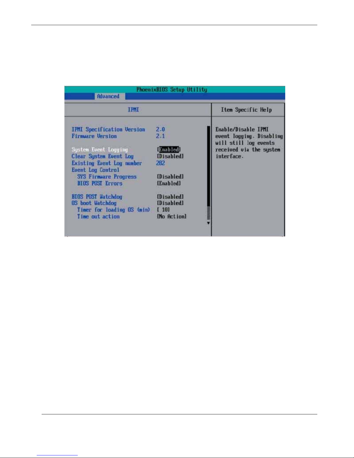
RES-12DCX Installation Manual
C.4.12 X IPMI (Only when an IPMI card is installed)
C-24
Figure C-3. The Advanced BIOS Setup IPMI Submenu
C.4.12.1IPMI Specification Version
This item displays the current IPMI Version.
C.4.12.2Firmware Version
This item displays the current Firmware Version.
C.4.12.3System Event Logging
Select Enabled to enable IPMI Event Logging. When this function is set to Disabled,
the system will continue to log events received via system interface. The options are
Enabled and Disabled.
Themis Computer
 Loading...