

Page 1

I ns tallation
I ns tallation
Manual
Manual
GbE XMC
GbE XMC
Ethernet Card
Ethernet Card
XMC Module Ethernet card/
Intel 82571 Gigabit Ethernet
Controller based GbE XMC Module
Page 2
Intel 82571 Gigabit Ethernet Controller based GbE XMC Module
Intel 82571 Gigabit Ethernet Controller based GbE XMC Module
Intel 82571 Gigabit Ethernet Controller based GbE XMC Module
Intel 82571 Gigabit Ethernet Controller based GbE XMC Module
Intel 82571 Gigabit Ethernet Controller based GbE XMC Module
Intel 82571 Gigabit Ethernet Controller based GbE XMC Module
Intel 82571 Gigabit Ethernet Controller based GbE XMC Module
Intel 82571 Gigabit Ethernet Controller based GbE XMC Module
GbE XMC Ethernet Card
GbE XMC Ethernet Card
GbE XMC Ethernet Card
GbE XMC Ethernet Card
GbE XMC Ethernet Card
GbE XMC Ethernet Card
GbE XMC Ethernet Card
GbE XMC Ethernet Card
GbE XMC Ethernet Card
GbE XMC Ethernet Card
GbE XMC Ethernet Card
GbE XMC Ethernet Card
GbE XMC Ethernet Card
GbE XMC Ethernet Card
GbE XMC Ethernet Card
GbE XMC Ethernet Card
Page 3

GbE XMC Ethernet Card
Installation Manual
Version 1.0— November 2011
Themis Computer—Americas and Pacific Rim
47200 Bayside Parkway
Fremont, CA 94538
Phone (510) 252-0870
Fax (510) 490-5529
http://www.themis.com
Themis Computer—Rest of World
5 Rue Irene Joliot-Curie
38320 Eybens, France
Phone +33 476 14 77 80
Fax +33 476 14 77 89
Page 4

Copyright © 2011 Themis Computer, Inc.
ALL RIGHTS RESERVED. No part of this publication may be reproduced in any form, by
photocopy, microfilm, retrieval system, or by any other means now known or hereafter invented without
the prior written permission of Themis Computer.
The information in this publication has been carefully checked and is believed to be accurate. However,
Themis Computer assumes no responsibility for inaccuracies. Themis Computer retains the right to
make changes to this publication at any time without prior notice. Themis Computer does not assume
any liability arising from the application or use of this publicat ion or the product(s) described herein.
RESTRICTED RIGHTS LEGEND: Use, duplication, or disclosure by the United States Government
is subject to the restrictions set forth in DFARS 252.227-7013 (c)(1)(ii) and FAR 52.227-19.
TRADEMARKS
THEMIS® is a registered trademark of Themis Computer, Inc.
®
Intel
is a registered trademark of the Intel Corporation.
®
Samtec
All other trademarks or registered trademarks used in this publication are the property of their
respective owners.
is a registered trademark of Samtec, Inc.
Safety Precautions
Instructions regarding safety precautions during installation, operation, or maintenance of the equipment
are given in the section entitled “Safety Instructions” on page iv.
WARNINGS and CAUTIONS
The definitions of WARNINGS and CAUTIONS as used in this document are given in the Preface in
the section entitled “Notes, Cautions, Warnings, and Sidebars”.
Themis Customer Support
North America, South America, and Pacific Rim
Telephone: 510-252-0870
Fax: 510-490-5529
E-mail: [email protected]
Web Site: http://www.themis.com
GbE XMC Ethernet Card Installation Manual, Version 1.0
November 2011
Manual Part Number: 118470-024
Page 5

GbE XMC Ethernet Card Installation Manual
Version Revision History
Ve rsio n 1.0 .................................................................................... November 2011
Themis Computer
iii
Page 6
GbE XMC Ethernet Card Installation Manual Version 1.0
Safety Instructions
To maximize user safety and ensure correct device operation, all instructions contained in this section should be read carefully.
Caution: It is important that the user observe all warnings and instructions
that are on the device and contained in this manual.
• The device must be used in accordance with the instructions for use.
• Electrical installations in the room must correspond to the requirements of
respective regulations.
• Take care that there are no cables, particularly mains cables, in areas where
persons can trip over them.
• Do not use a mains connection in sockets shared by a number of other power
consumers. Do not use an extension cable.
• Only use the mains cable supplied.
• The unit is completely disconnected from the power source only when the
power cord is disconnected from the power source. Therefore the power cord
and its connectors must always remain easily accessible.
• Do not set up the device in the proximity of heat sources or in a damp location.
Make sure the device has adequate ventilation.
• All connection cables must be screwed or locked to the chassis housing.
• The device is no longer safe to operate when
— the device has visible damage or
— the device no longer functions.
• In these cases, the device must be shut down and secured against unintentional
operation.
• Repairs may only be carried out by a person authorized by Themis Computer.
• The device may only be opened for the installation and removal of extension
(PCI) cards, memory modules, storage drives, fan housings, power supplies,
and the lithium battery—all in accordance with the instructions given in this
and correlating manuals.
iv
Themis Computer
Page 7

• If extensions are made to the device, the legal stipulations and the device specifications must be observed.
• The device must be switched off when removing the top cover; for example,
before installing extension (PCI) cards.
Electrostatic Discharge (ESD)
A sudden discharge of electrostatic electricity can destroy static-sensitive devices
or micro-circuitry. Proper packaging and grounding techniques are necessary precautions to prevent damage. Always take the following precautions:
1. Transport boards in static-safe containers such as boxes or bags.
2. Keep electrostatic-sensitive parts in their containers until they arrive at static-
free stations.
3. Always be properly grounded when touching a sensitive board, component, or
assembly.
GbE XMC Ethernet Card Installation Manual
4. Store electrostatic-sensitive boards in protective packaging or on conductive
foam.
Grounding Methods
Guard against electrostatic damage at workstations by following these steps:
1. Cover workstations with approved anti-static material. Provide a wrist strap
connected to a work surface and properly grounded tools and equipment.
2. Use anti-static mats, heel straps, or air ionizers to give added protection.
3. Handle electrostatic-sensitive components, boards, and assemblies by the case
or the PCB edge.
4. Avoid contact with pins, leads, or circuitry.
5. Turn off power and input signals before inserting and removing connectors or
test equipment.
6. Keep the work area free of non-conductive materials such as ordinary plastic as-
sembly aids and Styrofoam.
7. Use field service tools, such as cutters, and screwdrivers that are conductive.
8. Always place drives and boards PCB-assembly-side down on the foam.
Themis Computer
v
Page 8

GbE XMC Ethernet Card Installation Manual Version 1.0
vi
Themis Computer
Page 9

Table of Contents
Version Revision History....................................................................................................... iii
Safety Instructions ................................................................................................................. iv
Preface.................................................................................................................................. xvii
1. GbE XMC Overview and Specifications .................................................................... 1-1
1.1 Main Features ........................................................................................................ 1-3
1.2 Environmental ........................................................................................................ 1-4
1.3 Technical Support .................................................................................................. 1-4
2. Hardware Installation ..................................................................................................2-1
2.1 Hardware Installation ............................................................................................. 2-1
A. Connector Pinouts and LEDs ..................................................................................... A-1
A.1 I/O Port Specifications .......................................................................................... A-1
A.2 GbE Card Front-Panel Connectors ....................................................................... A-2
A.2.1 Gigabit Ethernet (GbE) ............................................................................. A-2
A.3 XMC Connector .................................................................................................... A-3
A.4 Front-Panel LEDs ................................................................................................. A-6
A.4.1 PCB LEDs ................................................................................................. A-7
Appendix B. Solder Beads ................................................................................................B-1
B.1 Factory-Configurable Solder Beads .......................................................................B-1
B.1.1 GbE XMC Ethernet Card Solder Beads ....................................................B-1
Index ............................................................................................................................. Index-1
Reader Comment Card
Themis Computer
v
Page 10

GbE XMC Ethernet Card Installation Manual Version 1.0
vi
Themis Computer
Page 11

Table of Contents
List of Figures
Figure 1 GbE XMC Ethernet Card................................................................................. xvii
Figure 2 Three-Quarter Front View of the XV1,XV2,LV1.......................................... xviii
Figure 3 Three-Quarter Front View of the GbE Card..................................................... xix
Figure 4 Front View of the GbE Card............................................................................. xix
Figure 1-1 GbE XMC Ethernet Card................................................................................. 1-1
Figure 1-2 GbE XMC Ethernet Card Block Diagram....................................................... 1-2
Figure 1-3 Intel 82571EB Ethernet Controller.................................................................. 1-4
Figure 2-1 Host System Board for the GbE ...................................................................... 2-2
Figure 2-2 GbE XMC Ethernet Card................................................................................. 2-2
Figure A-1 GbE XMC Ethernet Card I/O Ports............................................................... A-1
Figure A-2 Gigabit Ethernet RJ45 Connector Pinout........................................................ A-2
Figure A-3 GbE XMC Connector Pinout......................................................................... A-3
Figure A-4 GbE Front-Panel LEDs.................................................................................. A-6
Figure A-5 GbE PCB LEDs (Bottom Side) ..................................................................... A-7
List of Tables
Table A-1 Gigabit Ethernet Connector-Pin Signals and LED Interpretation .................. A-2
Table A-2 GbE XMC Signal Descriptions....................................................................... A-3
Table A-3 GbE Front-Panel LED Behavior..................................................................... A-6
Table A-4 GbE Card PCB LED Descriptions (Bottom Side).......................................... A-8
Themis Computer
vii
Page 12

GbE XMC Ethernet Card Installation Manual Version 1.0
viii
Themis Computer
Page 13

Preface
This document, entitled GbE XMC Ethernet Card Installation Manual, provides a
hardware overview of the Themis GbE XMC Ethernet Card (see Figure 1 below),
which is based on the Intel 82571 Gigabit Ethernet Controller.
GbE XMC Ethernet Card is supported by XMC based platforms such as:
• Themis XV2 6RU VME64 Platform single board computer
• Themis XV1 6RU VME64 Platform single board computer
• Themis LV1 6RU VME64 Platform single board computer
(Each product mentioned above can be found in the following figure:
XV1;XV2;LV1, Figure 2 on page xviii).
.
Themis Computer
Figure 1. GbE XMC Ethernet Card
xvii
Page 14

GbE XMC Ethernet Card Installation Manual Version 1.0
xviii
Figure 2. Three-Quarter Front View of the XV1,XV2,LV1
Themis Computer
Page 15

Preface
The GbE XMC Ethernet Card has been designed to fit on to a standard XMC carrier
board and is provided with installation hardware (not shown). The GbE Card is rugged enough to meet the demands associated with such markets as the military, aerospace, and telecommunications industries.
Figure 3. Three-Quarter Front View of the GbE Card
Themis Computer
Figure 4. Front View of the GbE Card
xix
Page 16

GbE XMC Ethernet Card Installation Manual Version 1.0
The GbE Card is based upon the Intel 82571 Gigabit Ethernet Controller which utilizes PCI Express architecture v1.0a. The XMC connector also allows for a x4 PCIe
connection between the GbE Card and host board. The small form factor of the GbE
XMC Ethernet Card allows for tight space constraints yet powerfull enough for both
server and workstation network designs.
The GbE XMC Ethernet Card is based on the functionality and capability of the following Intel chip:
• Intel 82571EB Gigabit Ethernet Controller
An overview of GbE XMC Ethernet Card design and specifications is given in
Chapter 1, "GbE XMC Overview and Specifications", of this manual.
Connector pinout, LED, and solder bead descriptions are given in the Appendices of
this manual.
This manual is intended for an experienced system administrator with a knowledge
of networking, VME based platforms, high-speed single board computers, and current OS software.
Website Information
Themis Computer corporate and product information may be accessed on the World
Wide Web by browsing the website http://www.themis.com.
Your Comments are Welcome
We are interested in improving our documentation and welcome your comments and
suggestions. You can email your comments to us at [email protected].
Please include the document part number (118470-024) in the subject line of your
email.
xx
Themis Computer
Page 17
Preface
Notes, Cautions, Warnings, and Sidebars
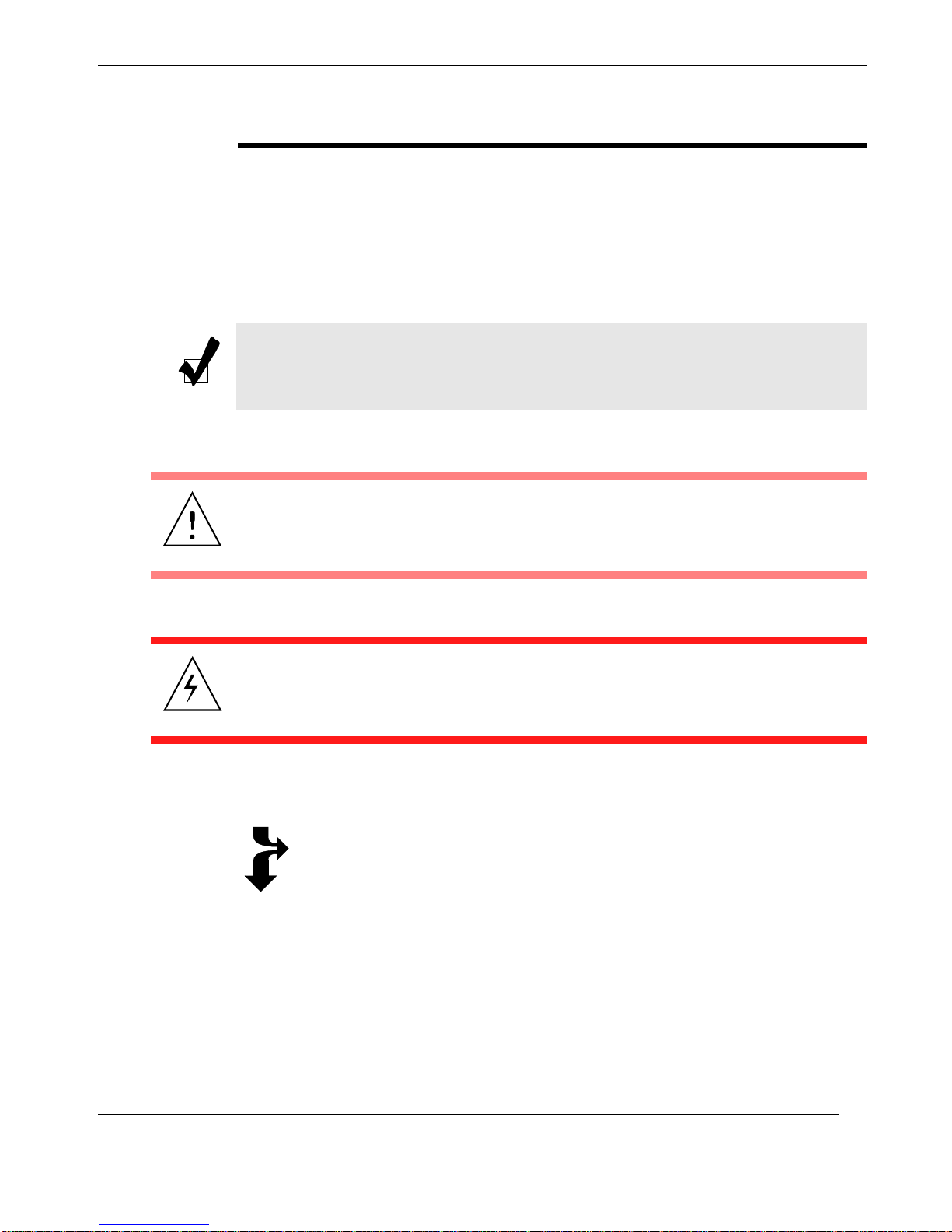
The following icons and formatted text are included in this document for the reasons
described:
Note: A note provides additional information concerning the procedure or action
being described.
Caution: A caution describes a procedure or action that may result in damage to
the equipment. This may involve—but is not restricted to—heavy equipment or
sharp objects. T o reduce the risk, follow the instructions accompanying this symbol.
Themis Computer
Warning: A warning describes a procedure or action that may cause injury or death
to the operator as a result of hazardous voltages. To reduce the risk, follow the instructions accompanying this symbol.
Sidebar: A “sidebar” adds detail to the section within which it is placed,
but is not absolutely vital to the description or procedure of the section.
xxi
Page 18

GbE XMC Ethernet Card Installation Manual Version 1.0
xxii
Themis Computer
Page 19

SATA
(Not Used)
XMC Connector
Intel Ethernet Controller
RJ-45
Ethernet Port
RJ-45
Ethernet Port
Introductory
Section
GbE XMC Overview and Specifications
The Themis GbE XMC Ethernet Card (see Figure 1-1) is a 10/100/1000 ethernet
solution that is installed and runs on XMC-based system platforms such as the Themis XV2 single-board computer. The GbE XMC utilizes PCIe v1.0a standard for
high speed and low latency.
Chapter
1
Themis Computer
Figure 1-1. GbE XMC Ethernet Card
1-1
Page 20
GbE XMC Ethernet Card Installation Manual Version 1.0
RJ-45
RJ-45
SATA
Connector
Cable
Intel
MUX
I2C FRU
64 kbit
SPI Flash
1 Mbit
SPI EEPROM
128 kb it
LTC 3 412A
3.3V to 1.8V
LTC 3 412A
3.3V to 1.8V
XMC
Connector
(SATA not used)
3.3V1.8V
1.1V
PCIe x4
LAN0_MDI
LAN1_MDI
SATA
PCIe x1
PCIe x3 / PCIe x4
XMC_GA0
SATA / PCIe x1
82571EB
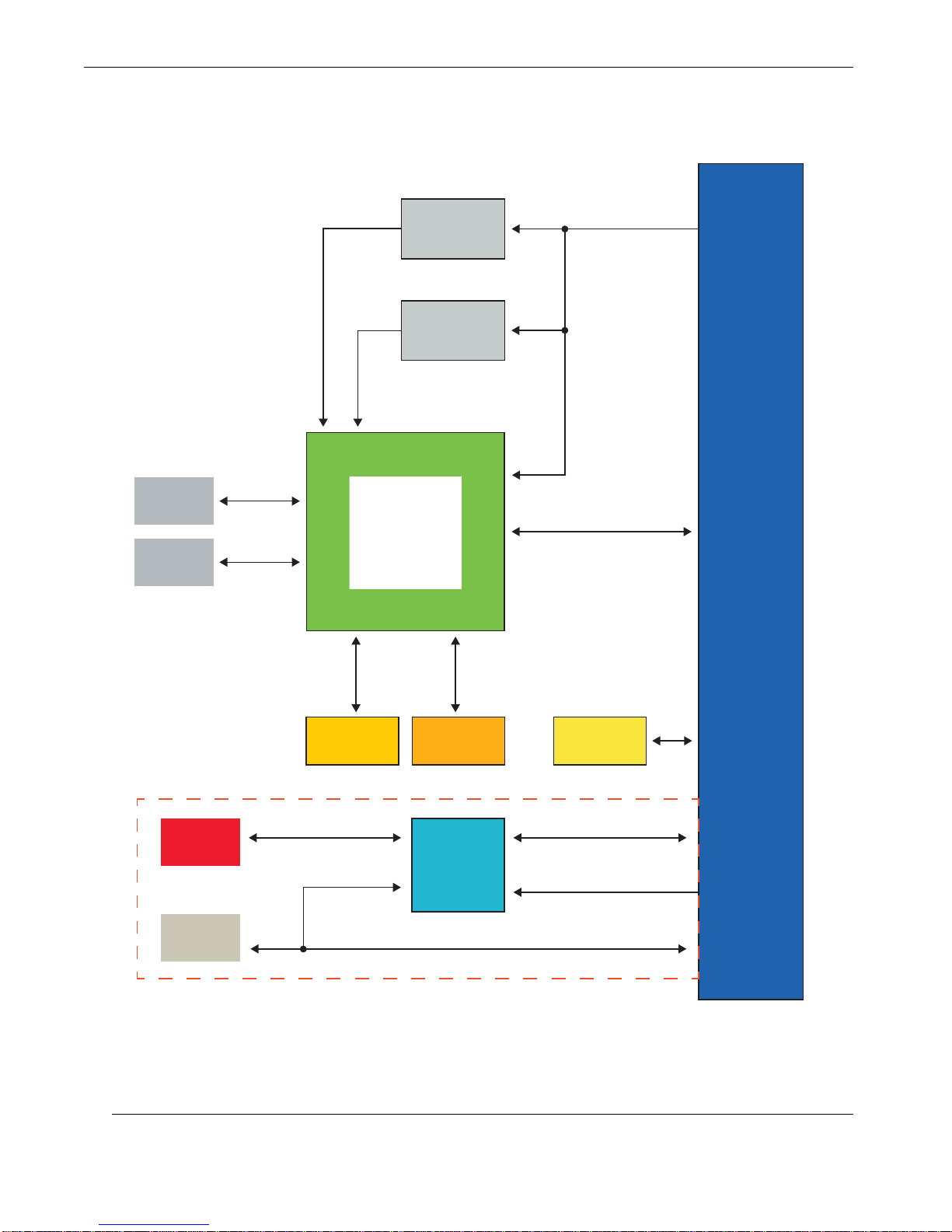
Note: Not used in a typical configuration. This section is only used when the GbE Card is cabled to a 2PX2 Carrier Board
Figure 1-2 below is a block diagram of the Themis GbE XMC Ethernet Card.
Figure 1-2. GbE XMC Ethernet Card Block Diagram
1-2
Themis Computer
Page 21

1.1 Main Features
The GbE XMC Ethernet Card offers the following features based upon the Intel
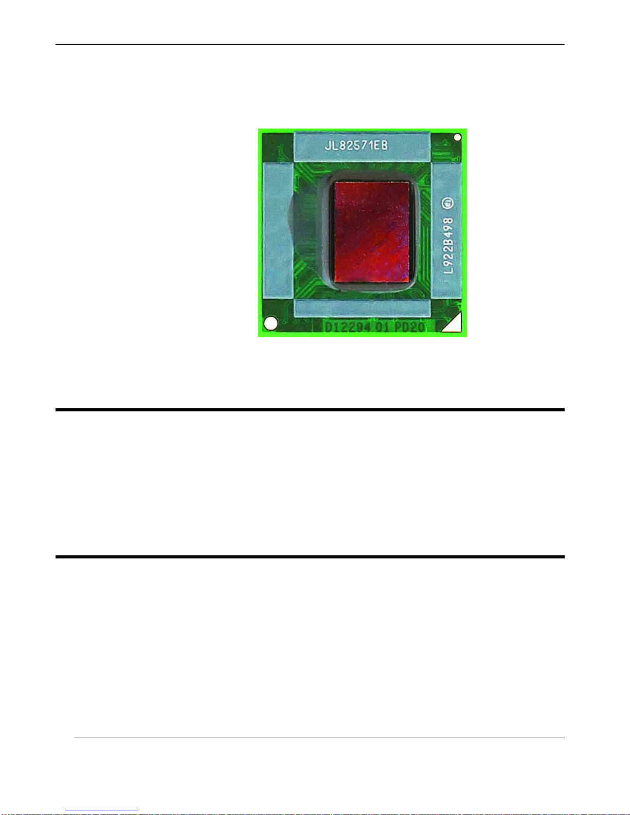
82571EB Ethernet Controller (see Figure 1-3 on page 1-4):
• Two RJ-45 10/100/1000 ethernet Ports
• Highly visible activity and link speed LEDs next to each RJ-45 port
• x4 PCI-E gen 1.0a interface with the Intel 82571EB Ethernet Controller
• 3.3V power from the XMC
• Two full-integrated Gigabit Ethernet Media Access Control (MAC) and physical layer (PHY) ports
• IEEE 802.3 Ethernet interface
1—GbE XMC Overview and Specifications
• Supports 1000BASE-T, 100BASE-TX, and 10BASE-T
• Management of PCI Express packet traffic across transaction, link and physical/logical layers
• Advanced Interrupt handling
• Parallel and pipe-lined logic architecture optimized for gigabit ethernet
• Supports Jumbo Frames
• 48 KByte per port on-chip packet buffer
• Use of efficient ring buffer descriptor data structures, with up to 64 packet
descriptors cached on-chip
• High performance and low memory latency
• Cable up connection (P16) available for integrating the GbE into a system with
a carrier card (Recommended connection is through the XMC)
Themis Computer
1-3
Page 22
GbE XMC Ethernet Card Installation Manual Version 1.0
Figure 1-3. Intel 82571EB Ethernet Controller
1.2 Environmental
The GbE XMC Ethernet Card has been tested and rated for operation within the temperature range of -5°C – 55°C.
For testing purposes, the GbE XMC Ethernet Card was qualified in the middle slot
on the Themis XV1 with 19 CFM of airflow per slot.
1.3 Technical Support
For assistance and other information not found in this document concerning the GbE
XMC Ethernet Card or any other Themis product, please call Themis Customer Support in Fremont, CA, USA, at +1 (510) 252-0870, or E-mail: [email protected].
For all inquiries by phone, Themis operational hours are: 8:00am—5:00pm Pacific
Standard Time. Additional information can also be found by going to
www.themis.com.
1-4
Themis Computer
Page 23

Installation
Section
Hardware Installation
2.1 Hardware Installation
The GbE XMC Ethernet Card can be installed within any product that supports
XMC module-card protocol, such as Themis XV2 single-board VME-based computer system.
Chapter
2
Themis Computer
To install the GbE XMC Ethernet Card, follow these steps:
1. Remove the blank PMC/XMC faceplate or existing card from the XMC mod-
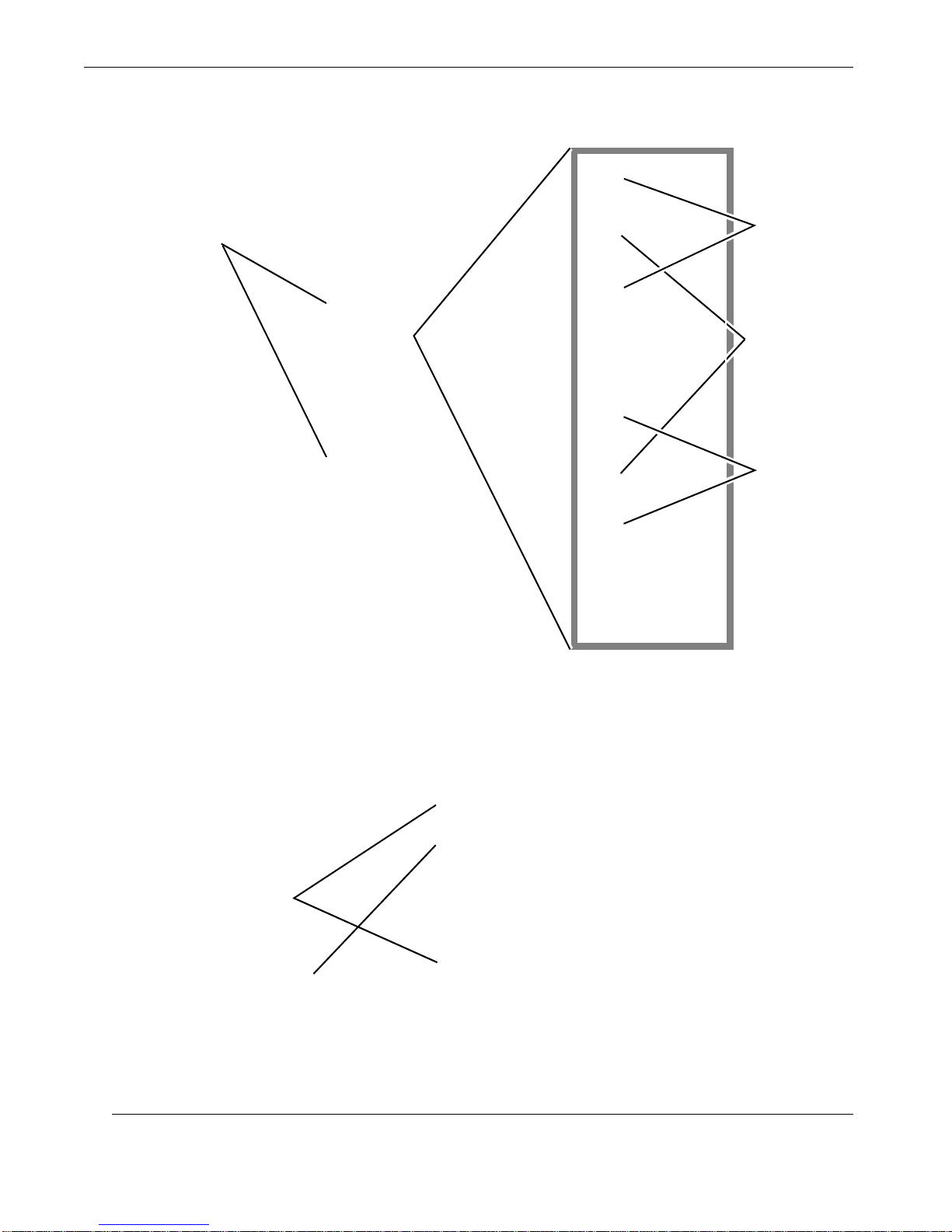
ule slot on the host system board (see Figure 2-1 on page 2-2).
2. Insert the GbE into the XMC-card opening with the proper orientation and
align the XMC connector with the mating connector on the host board.
3. Press the XMC connector into the mating host-PCB connector until the GbE
is firmly seated.
4. To secure the GbE to the host PCB, use two threaded standoffs on the GbE
(see Figure 2-2, page 2-2) and attach to the two mounting holes (see Figure
2-1 on page 2-2) on the host PCB with two M2.5x5mm panhead screws.
Attach the two threaded standoffs to the host PCB with the two screws.
Important: If your GbE card is being installed into a system that has stand-
offs already attached to the host PCB, the GbE standoffs should be removed.
All necessary hardware will be provided with the order.
2-1
Page 24
GbE XMC Ethernet Card Installation Manual Version 1.0
Remove Blank
PMC/XMC Faceplate(s)
XMC connectors
(without standoffs
installed)
Holes for standoffs
Holes for standoffs
XMC connector
Standoffs
2-2
Figure 2-1. Host System Board for the GbE
Figure 2-2. GbE XMC Ethernet Card
Themis Computer
Page 25

A
Ethernet PortEthernet Port <RJ–45>
Appendix
Connector Pinouts and LEDs
This appendix provides the I/O port specifications for the GbE XMC Ethernet Card.
A.1 I/O Port Specifications
GbE external I/O ports, two RJ–45 Ethernet ports (see Figure A-1), are accessible
through the I/O connectors on the GbE bezel panel (faceplate).
Figure A-1. GbE XMC Ethernet Card I/O Ports
Both RJ–45 Ethernet ports are described in the following sections of this appendix,
along with LED behaviors. Drawings of the I/O ports are provided to display physical pin locations followed by a table describing signal definitions.
Themis Computer
A-1
Page 26
GbE XMC Ethernet Card Installation Manual Version 1.0
Symbol
Baseboard
Link Speed LEDNetwork Traffic LED
Pin 8
Pin 1
A.2 GbE Card Front-Panel Connectors
A.2.1 Gigabit Ethernet (GbE)
Connector Type: Single RJ–45 GbE Connector, 8–Pin
Manufacturer; Part Number: Tyco; 1116503-2
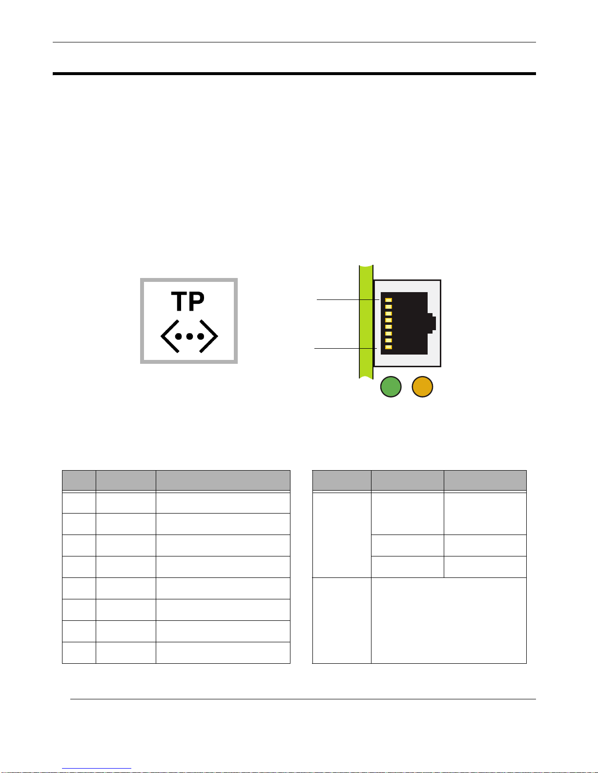
The GbE Card provides two Gigabit Ethernet ports on its front panel. The RJ45 (8pin) GBE connector supports 10/100/1000Base-T transmission (see Figure A-2 and
Table A-1 below).
Figure A-2. Gigabit Ethernet RJ45 Connector Pinout
Table A-1. Gigabit Ethernet Connector-Pin Signals and LED Interpretation
Pin Signal Description LED LED Color Interpretation
1 BI_DA+ Bi-directional pair A+
2 BI_DA– Bi-directional pair A–
3 BI_DB+ Bi-directional pair B+ Green 100 Mb/s
4 BI_DC+ Bi-directional pair C+ Amber 1000 Mb/s
5 BI_DC– Bi-directional pair C–
6 BI_DB– Bi-directional pair B–
7 BI_DD+ Bi-directional pair D+
8 BI_DD– Bi-directional pair D–
A-2
Yellow/Green
(Right )
= Link
Speed
Green
(Left )
= Network
Traffic
OFF 10 Mb/s
Flashing rate is 300 ms for
transmit/receive activity.
Themis Computer
Page 27
A.3 XMC Connector
Pin A1
Pin F1 Pin F19
Pin A19
Note: Column 1 starts on the edge
with the larger keyed opening
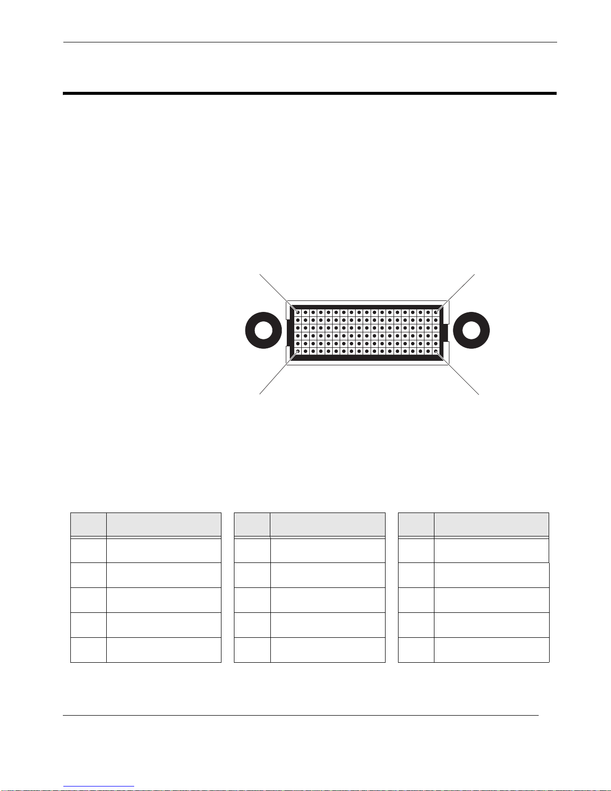
• Connector Type: 6-row x 19-pins, 114-pin (male) module connector
• Manufacturer; Part: Samtec; ASP-103614-04
The (male) XMC connection on the GbE XMC Ethernet Card allows it to be con-
nected to any available XMC carrier slot on a SBC (Single Board Computer). The
GbE supports a x4 PCI-E gen 1.0a link through its XMC connector.
A—Connector Pinouts and LEDs
Figure A-3. GbE XMC Connector Pinout
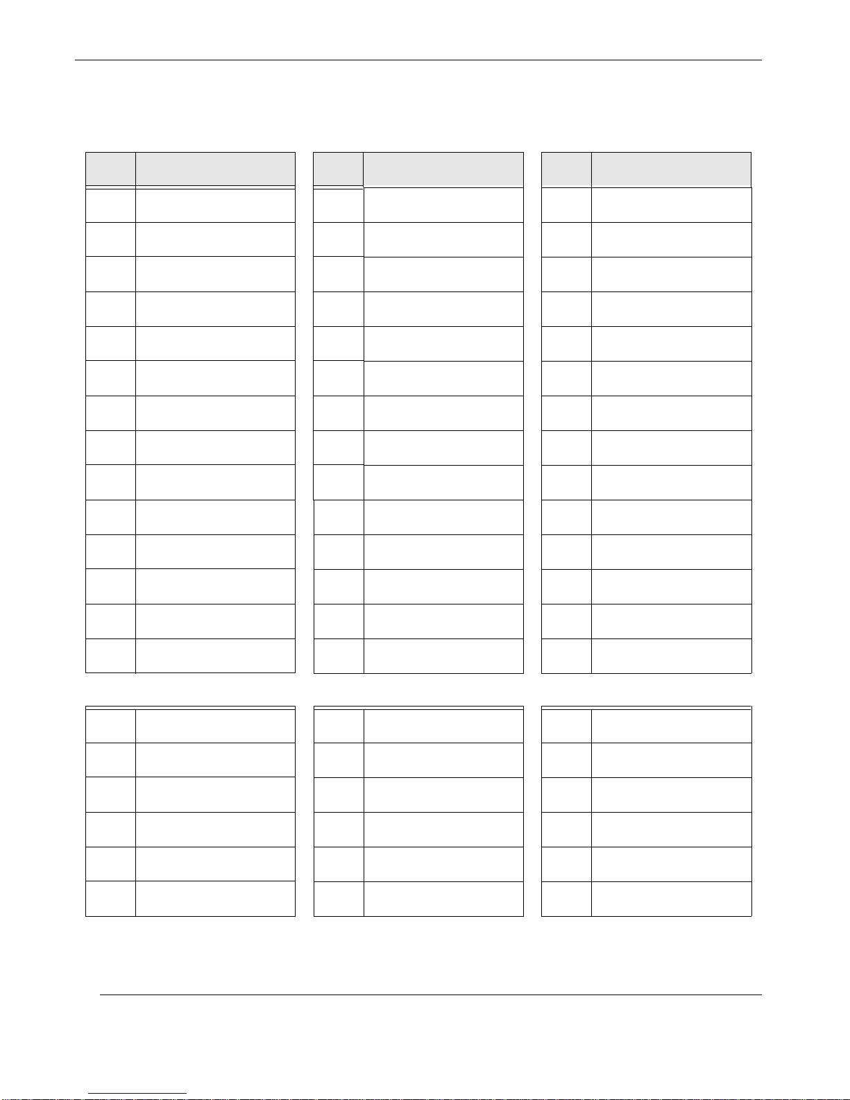
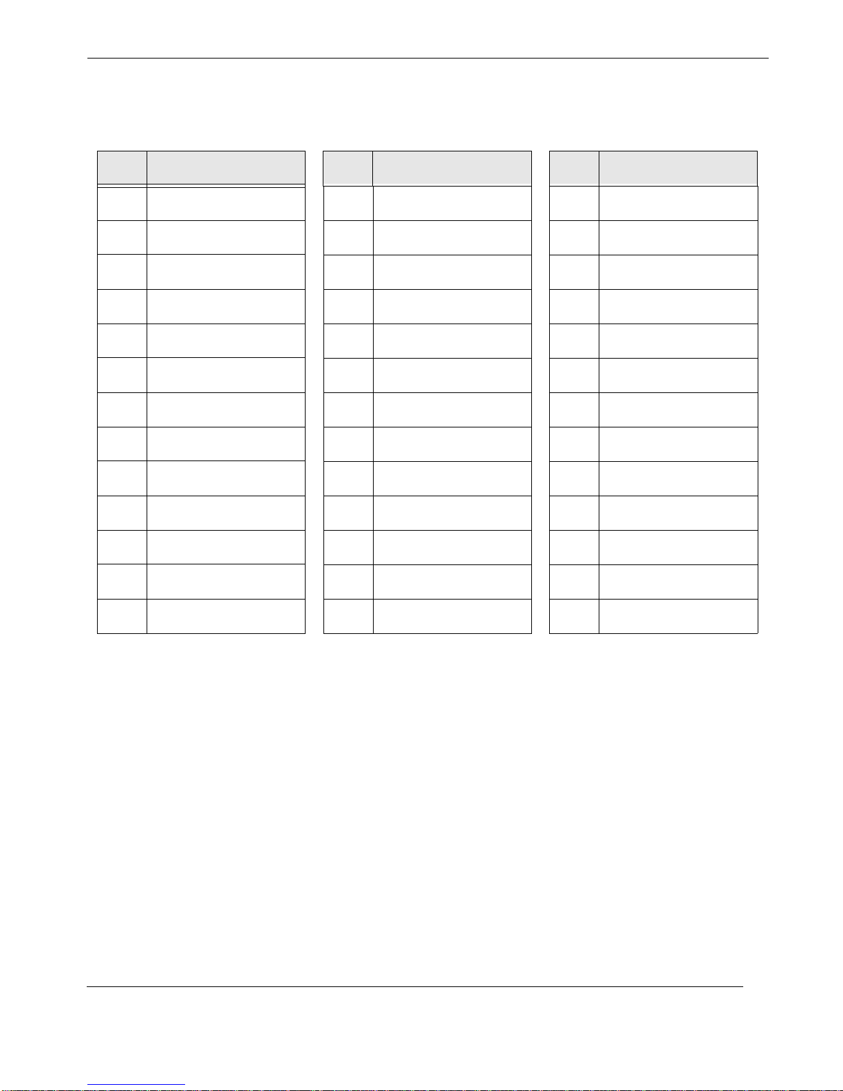
XMC connector pin signals on the GbE are described in Table A-2.
Table A-2. GbE XMC Signal Descriptions
Pin Signal Pin Signal Pin Signal
A1 PCIe_TX0_P B1 PCIe_TX0_N C1 V_3V3
A2 GND B2 GND C2 No Connection
A3 PCIe_TX2_P B3 PCIe_TX2_N C3 V_3V3
A4 GND B4 GND C4 No Connection
A5 PCIe_TX4_P B5 PCIe_TX4_N C5 V_3V3
Themis Computer
A-3
Page 28
GbE XMC Ethernet Card Installation Manual Version 1.0
Table A-2. GbE XMC Signal Descriptions (Continued)
Pin Signal Pin Signal Pin Signal
A6 GND B6 GND C6 No Connection
A7 PCIe_TX6_P B7 PCIe_TX6_N C7 V_3V3
A8 GND B8 GND C8 XMC_TDI
A9 No Connection B9 No Connection C9 No Connection
A10 GND B10 GND C10 XMC_TDO
A11 PCIe_RX0_P B11 PCIe_RX0_N C11 SYS_RDY
A12 GND B12 GND C12 XMC_GA1
A13 PCIe_RX2_P B13 PCIe_RX2_N C13 No Connection
A14 GND B14 GND C14 XMC_GA2
A15 PCIe_RX4_P B15 PCIe_RX4_N C15 No Connection
A16 GND B16 GND C16 XMC_MVMRO
A17 PCIe_RX6_P B17 PCIe_RX6_N C17 No Connection
A18 GND B18 GND C18 PCIe_LANESPT
A19 PCIe_CLK_P B19 PCIe_CLK_N C19 No Connection
D1 PCIe_TX1_P E1 PCIe_TX1_N F1 No Connection
D2 GND E2 GND F2 PCIe_RST_N
D3 PCIe_TX3_P E3 PCIe_TX3_N F3 No Connection
D4 GND E4 GND F4 No Connection
D5 PCIe_TX5_P E5 PCI_TX5_N F5 No Conn ection
D6 GND E6 GND F6 No Connection
A-4
Themis Computer
Page 29
A—Connector Pinouts and LEDs
XMC Connector
Table A-2. GbE XMC Signal Descriptions (Continued)
Pin Signal Pin Signal Pin Signal
D7 PCIe_TX7_P E7 PCIe_TX7_N F7 No Connection
D8 GND E8 GND F8 No Connection
D9 No Connection E9 No Connection F9 No Connection
D10 GND E10 GND F10 XMC_GA0
D11 PCIe_RX1_P E11 PCIe_RX1_N F11 No Connection
D12 GND E12 GND F12 MPRESENT_N
D13 PCIe_RX3_P E13 PCIe_RX3_N F13 No Connection
D14 GND E14 GND F14 XMC_SDA
D15 PCIe_RX5_P E15 PCIe_RX5_N F15 No Connection
D16 GND E16 GND F16 XMC_SCL
D17 PCIe_RX7_P E17 PCIe_RX7_N F17 No Connection
D18 GND E18 GND F18 No Connectio n
D19 PCIe_WAKE_N E19 No Connection F19 No Co nn ec tio n
Themis Computer
A-5
Page 30
GbE XMC Ethernet Card Installation Manual Version 1.0
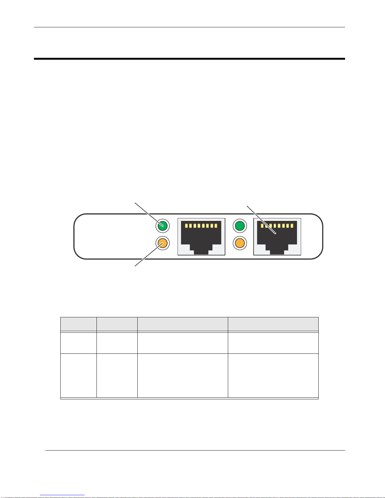
(A) link activity
(B) link speed
RJ–45 (8-Pin)
Ethernet Port
A.4 Front-Panel LEDs
•LED Type:Single Bi-Level, Dual LED
• Manufacturer; Part: Dialight; 553-0744F
This section is to describe the Font-Panel LEDs on the GbE XMC Ethernet Card.
Callouts indicating front-panel LEDs are shown in Figure A-4. Description and
interpretation of front-panel LEDs are given in Table A-3. Both pairs of LEDs oper-
ate with the same colors and behaviors. As such, only one LED set is mentioned in
the below figure and table.
.
A-6
Figure A-4. GbE Front-Panel LEDs
Table A-3. GbE Front-Panel LED Behavior
LED Callout Color Behavior
a
Top
(on)
a
Bottom
(off/on)
a—Reference to “Top” and “Bottom” applies to the orientation of the Front Panel as seen in Figure A-4.
A Green
B Off / Green / Amber
• This LED indicates ethernet link activity.
• This LED indicates ethernet link speed being 10
Mbit/s (off), 100 Mbit/s
(Green), or 1 Gbit/s (Amber).
Themis Computer
Page 31
A.4.1 PCB LEDs
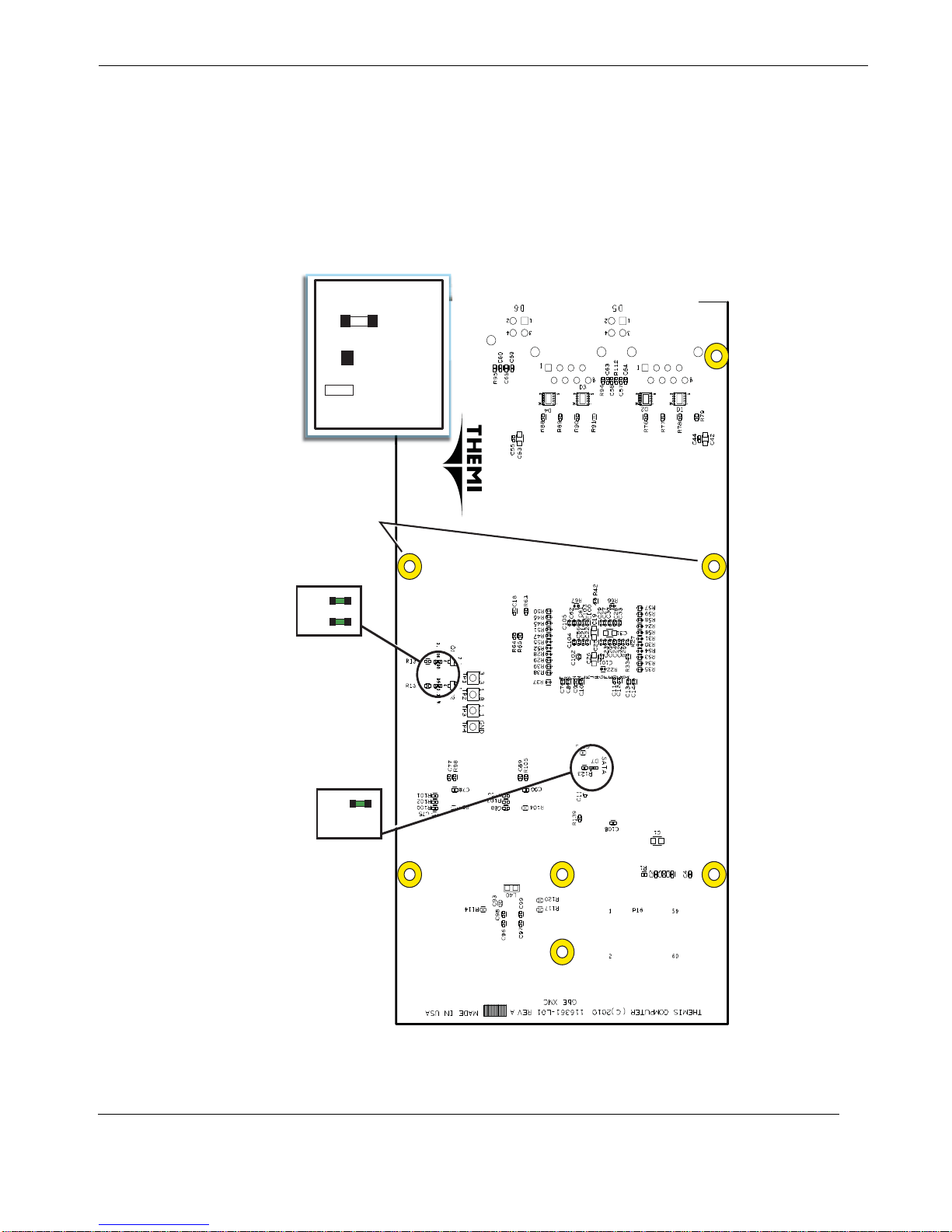
D8
D9
D7
(Not Used)
Note: Cable connect ion (P16) to 2PX2
Carrier Board is not used in a t ypical
configuration. Preferred connectio n
method is through the XMC connector
Heat sink and accompaning holes
not currently used. Pl ease contact
Themis if a heat sink solution is
required.
Legend
Board LED
= Actual location
of solder beads
= Color of the LED
= Component ID
D1
D1
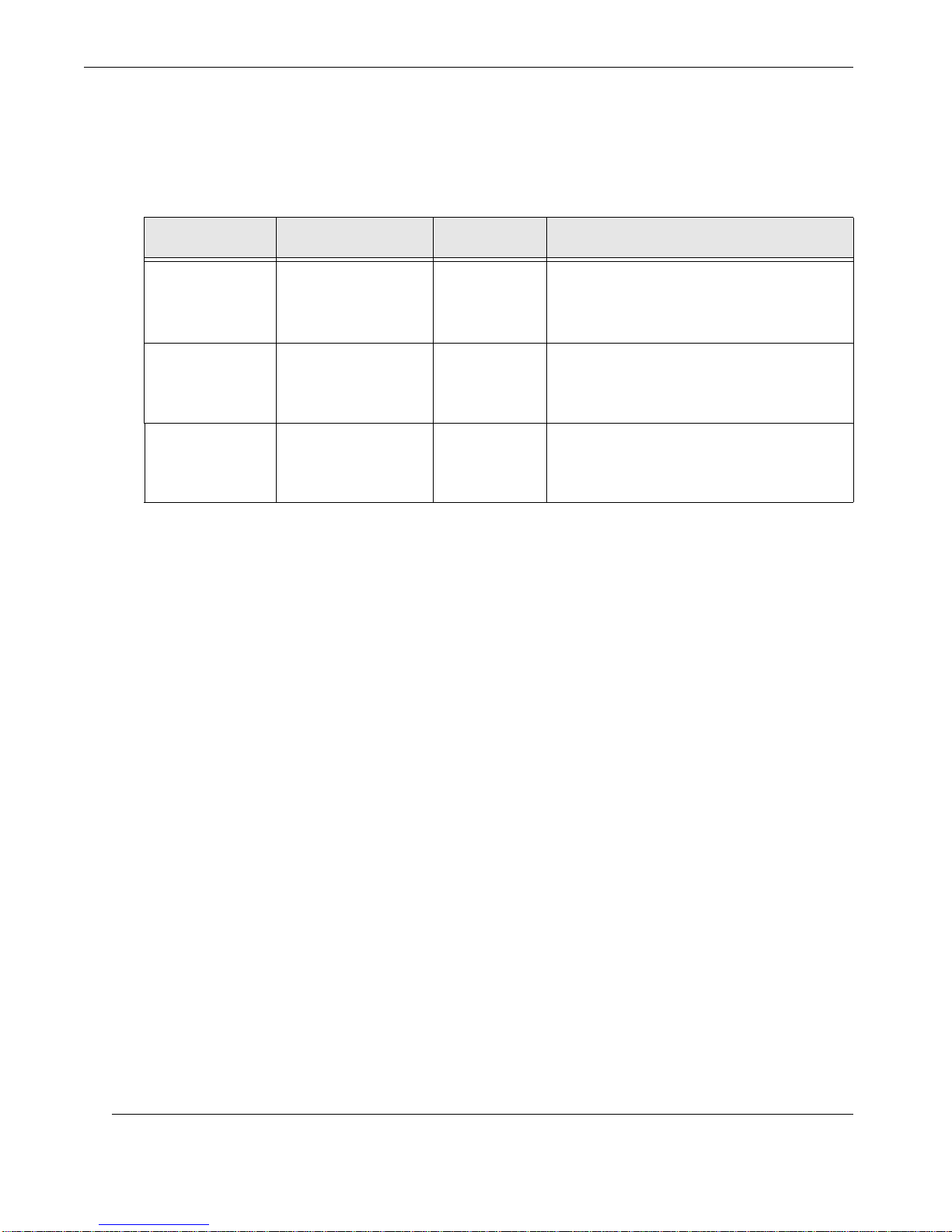
The GbE XMC Ethernet Card had three LEDs on the bottom side of the PCB. The
locations of the LEDs can be seen in Figure A-5 below. The LED color and descrip-
tion is located in Table A-4 on page A-8.
A—Connector Pinouts and LEDs
Front-Panel LEDs
S
Themis Computer
Figure A-5. GbE PCB LEDs (Bottom Side)
A-7
Page 32
GbE XMC Ethernet Card Installation Manual Version 1.0
Table A-4. GbE Card PCB LED Descriptions (Bottom Side)
LED ID Function Color Frequency and/or Interpretation
This LED (on) indicates SATA activity
D7 SATA Activity Green
D8 1.8V OK Green
D9 1.1V OK Green
Note: SAT A is not currently su pported on
the GbE XMC Ethernet Card
This LED (on) indicates 1.8V power is ok;
the board is generating 1.8V power within
spec.
This LED (on) indicates 1.1V power is ok;
the board is generating 1.1V power within
spec.
A-8
Themis Computer
Page 33
B
Appendix
Solder Beads
This appendix provides solder-bead locations and configurations for the GbE XMC
Ethernet Card. Solder beads are considered “factory-configurable” and must not be
altered by the user. If a solder bead requires reconfiguration, contact Themis Customer
Service.
Warning: Solder beads are set by Themis at the factory. Attempting to alter a solder-bead configuration could seriously damage the GbE XMC Ethernet Card. If you
encounter a problem, contact Themis Customer Support.
DO NOT ATTEMPT TO ALTER SOLDER-BEAD CONFIGURATIONS.
B.1 Factory-Configurable Solder Beads
B.1.1 GbE XMC Ethernet Card Solder Beads
The Themis GbE XMC Ethernet Card has no solder-beads, jumper-pins, or configurable settings on the PCB.
Themis Computer
B-1
Page 34

GbE XMC Ethernet Card Installation Manual Version 1.0
B-2
Themis Computer
Page 35

Index
Numerics
1.1V A-8
1.8V A-8
10/100/1000Base-T A-2
1000BASE-T 1-3
100BASE-TX 1-3
10BASE-T 1-3
3.3V input 1-3
82571EB 1-4
A
advanced interrupt handling 1-3
B
Block Diagram 1-2
C
cable up connection 1-3
Cautions xxi
Comments xx
connector pinouts A-1
Customer Support ii
E
G
GbE
Ethernet Controller 1-1
Features 1-3
Installation 2-1
Main Features 1-3
Overview 1-1
GbE bezel A-1
GbE Card (component side) xvii
GbE Card front panel xix
GbE Solder Beads B-1
GbE XMC Component Side 1-1
GbE XMC Ethernet Card xvii
Gigabit Ethernet A-2
H
Hardware Installation 2-1
Host System Board 2-2
I
I/O port specifications A-1
I/O Ports A-1
IEEE 802.3 1-3
Intel 82571EB xx
Ethernet
Connector Pin Signals and LEDs A-2
Connector Pinout A-2
F
faceplate A-1
factory-configurable B-1
Front Panel A-6
Front-Panel LED Behavior A-6
Front-Panel LEDs A-6
Themis Computer
J
Jumbo Frames 1-3
L
latency 1-3
LEDs A-6
LV1 xvii, xviii
M
MAC 1-3
Manual Part Number ii, xx
Index-1
Page 36

GbE XMC Ethernet Card Installation Manual Version 1.0
N
Notes xxi
O
on-chip packet buffer 1-3
P
packet descriptors 1-3
packet management 1-3
parallel logic architecture 1-3
PCB LEDs A-7
PHY 1-3
pipe-lined logic architecture 1-3
PMC/XMC faceplate 2-1
R
RJ-45 (8-pin) 1-3
RJ–45 Ethernet ports A-1
S
W
Warnings xxi
Website Information xx
X
x4 PCI-E gen 1.0a 1-3
XMC Connector A-3
Pinouts A-3
Signal Descriptions A-3
XV1 xvii, xviii
XV2 xvii, xviii, 2-2
XV2 single-board computer 2-1
Safety Instructions iv
Electrostatic Discharge (ESD) v
Grounding Methods v
Sidebars xxi
single board computer xvii
Solder Beads B-1
T
Themis contact information ii, 1-4
Themis Customer Support 1-4
Themis technical support 1-4
Themis XV2 single-board computer 1-1
V
Version Revision History iii
Version 1.0 iii
Vita 42.3 Compliant 1-3
VME64 Platform xvii
VME-based computer systems 2-1
Index-2
Themis Computer
Page 37

Themis Computer
47200 Bayside P arkway
Fremont, CA 94538
Attn: Publications Department
Place
Stamp
Here
Fold here; tape at top to seal
Page 38

Reader Comment Card
We welcome your comments and suggestions to help improve the T2GPX XMC Graphics Card
Installation Manual. Please take time to let us know what you think about this manual.
• Information provided in the manual was complete.
Agree___ Disagree___ Not Applicable___
• Information was well documented and easy to follow .
Agree___ Disagree___ Not Applicable___
• Information was easily accessible.
Agree___ Disagree___ Not Applicable___
• The manual was useful.
Agree___ Disagree___ Not Applicable___
• Please write down any comments you may have about this manual, including how it can be
improved:
___________________________________________________________
___________________________________________________________
___________________________________________________________
___________________________________________________________
___________________________________________________________
___________________________________________________________
___________________________________________________________
___________________________________________________________
___________________________________________________________
Name: _____________________________________________________
Title: _____________________________________________________
Company: _____________________________________________________
Address: _____________________________________________________
 Loading...