


SREXRG Module User Guide
SREXRG MODULE
(CC2530-CC2591 ZigBee Module)
USER GUIDE
Rev 1.2 Page 1

SREXRG Module User Guide
Contents
1 Introduction .......................................................................................................... 4
1.1 Purpose and scope .................................................................................................. 4
1.2 Revision History ...................................................................................................... 4
2 Module Application Circuit ..................................................................................... 5
2.1 Sample Application Connections ............................................................................. 5
2.2 Compliance Limits ................................................................................................... 6
2.3 Module Power Supply ............................................................................................. 6
3 Antenna Options and PCB Footprint........................................................................ 7
3.1 Footprint Overview ................................................................................................. 7
3.2 Module Footprint .................................................................................................... 8
4 Agency Statements ................................................................................................ 9
4.1 Federal Communication Commission Interference Statement................................. 9
4.2 ETSI (European Telecommunications Standards Institute) Statement ..................... 9
4.3 RF Exposure ............................................................................................................ 9
4.4 End Product Labelling............................................................................................ 10
5 Contact Detail ..................................................................................................... 10
Rev 1.2 Page 2

SREXRG Module User Guide
Figures
Figure 1: SREXRG Module Application Circuit ........................................................................ 5
Figure 2: Header Board Footprint Overview .......................................................................... 7
Figure 3: SREXRG Module Footprint Overview....................................................................... 8
Tables
Table 1: Compliance Limit ..................................................................................................... 6
Rev 1.2 Page 3
SREXRG Module User Guide
4
OCT
2012
Initial release
1.0
15OCT
2012
Section 2.2
updated
1.1
Section 2.2
updated
compliance limit
1 Introduction
1.1 Purpose and scope
The purpose of this document is to provide details regarding the use of SREXRG Module.
This document describes the connections between SREXRG Module and header board. This
connection details can be used to mount Module on other Host Board.
1.2 Revision History
Date Change Description Revision
29OCT2012
note
1.2
Rev 1.2 Page 4
SREXRG Module User Guide
2 Module Application Circuit
2.1 Sample Application Connections
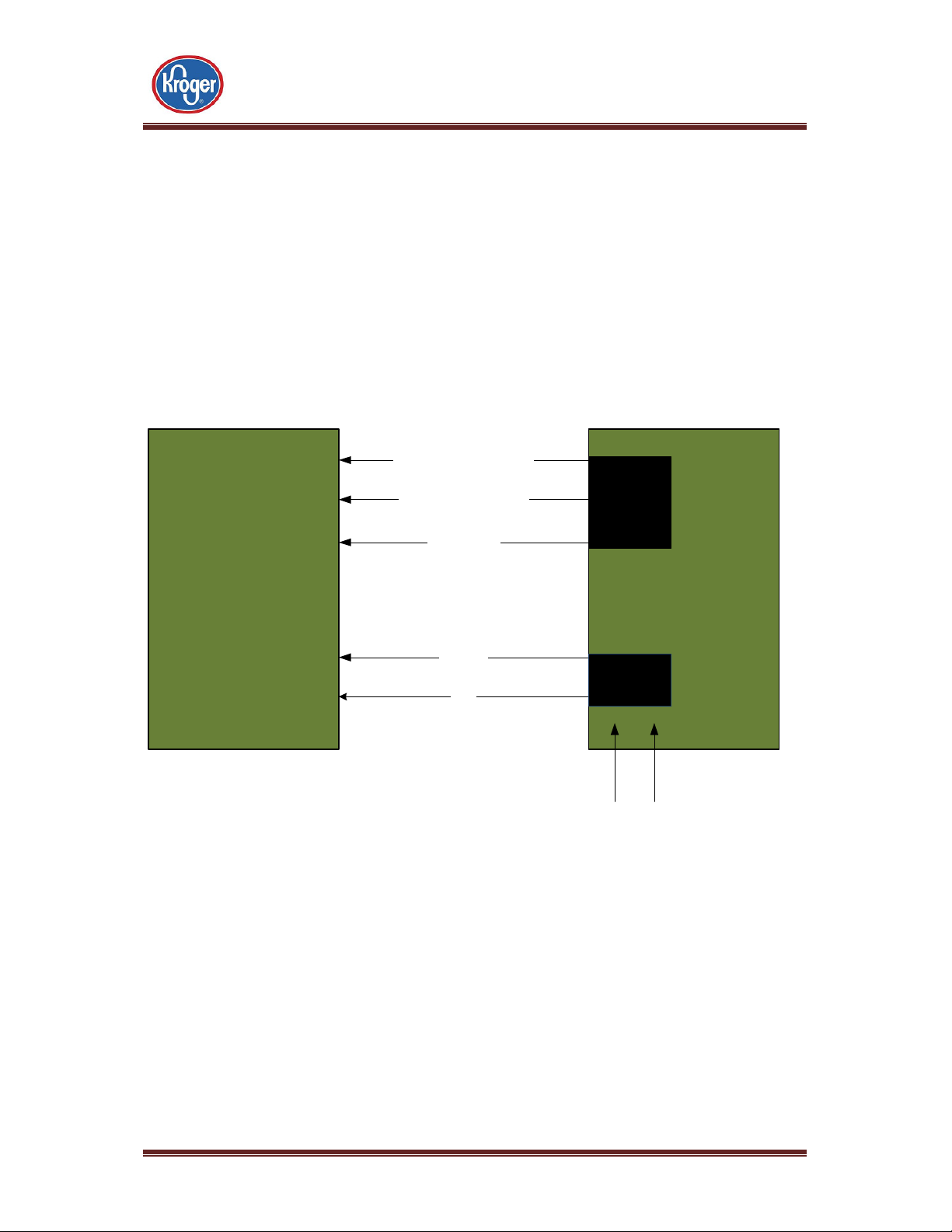
Figure 1 shows the circuit connection between SREXRG Module and Header board. Header
board provide the power supply to the SREXRG Module and also has debug header for
programming the CC2530 chip.
Below is the connection diagram of SREXRG module and header board.
P2_1
P2_2
RESET_N
SREXRG Module
AVDD and CVDD
GND
Figure 1: SREXRG Module Application Circuit
CC2530_Debug_DATA
CC2530_Debug_CLK
CC2530_RST
VCC3.3V
GND
Chipcon
Flashing
header
Header Board
3.3V
Charge
Pump
3.3V to 5V Input
From Battery or External
Source
Please refer SREXRG datasheet for module pin description. Based on application
requirements, host device can be interfaced with other pins on the module. Please refer TICC2530 user guide for connection/state information of unused pins.
Rev 1.2 Page 5
SREXRG Module User Guide
Compliance
TXPOWER
Register value
ETSI 0X55
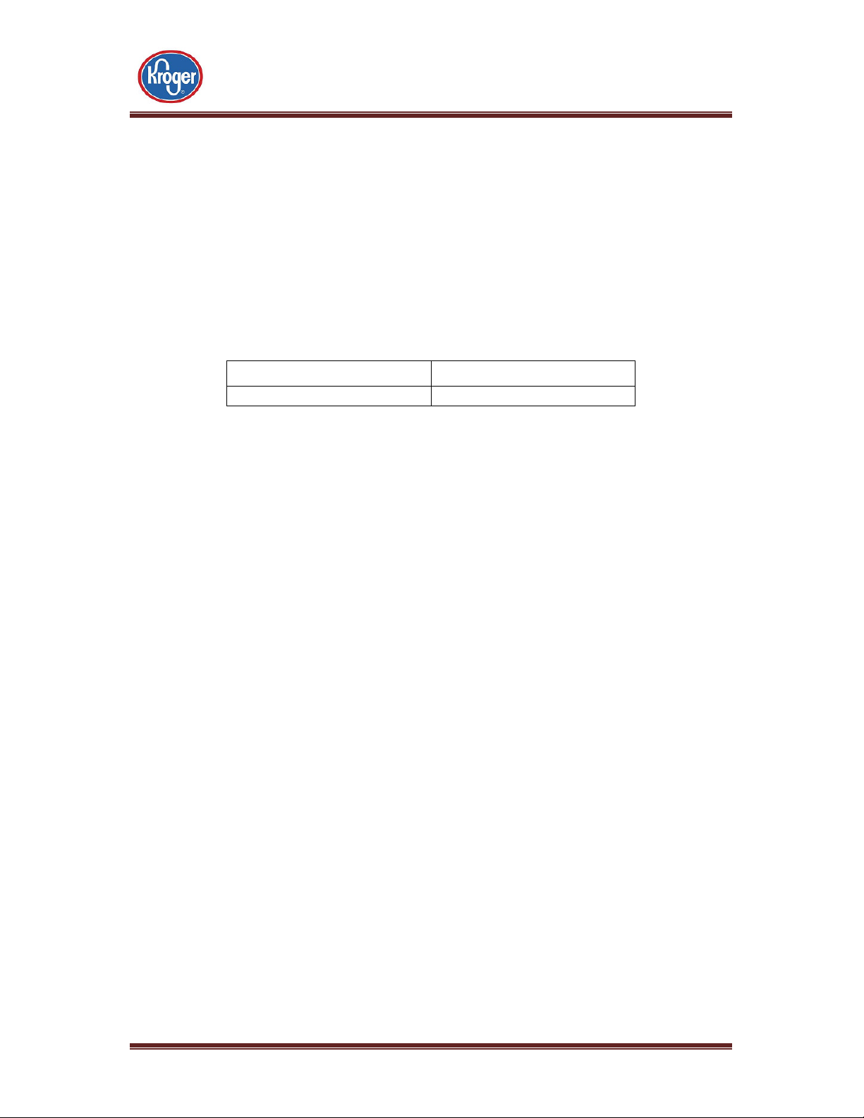
2.2 Compliance Limits
Depending on the country where the module is used, compliance limit needs to be set to
ensure the certification of module. Table 1 shows the setting up the proper power level to
meet compliance limits.
Table 1 shows the register value configuration for RF Power to meet compliance limit for
ETSI standard.
Table 1: Compliance Limit
Note: The register value used for FCC compliance is maximum value and cannot be
increased by end user. The RF Output Power configuration is not accessible to End User.
2.3 Module Power Supply
The SREXRG Module can operate between 2.7V to 3.6V power level. However, it is
recommended to provide nominal 3.3VDC supply to Module VCC and GND pins. For details
of VCC – GND pins; please refer Module datasheet.
Rev 1.2 Page 6

SREXRG Module User Guide
3 Antenna Options and PCB Footprint
3.1 Footprint Overview
Below figure shows the footprint detail of the SREXRG Header board.
Figure 2: Header Board Footprint Overview

SREXRG Module User Guide
3.2 Module Footprint
Figure 3 shows the Module footprint over the Header board
Figure 3: SREXRG Module Footprint Overview

SREXRG Module User Guide
4 Agency Statements
4.1 Federal Communication Commission Interference Statement
This equipment has been tested and found to comply with the limits for a Class B digital
device, pursuant to Part 15 of the FCC Rules. These limits are designed to provide
reasonable protection against harmful interference in a residential installation. This
equipment generates; uses and can radiate radio frequency energy and, if not installed and
used in accordance with the instructions, may cause harmful interference to radio
communications. However, there is no guarantee that interference will not occur in a
particular installation. If this equipment does cause harmful interference to radio or
television reception, which can be determined by turning the equipment off and on, the
user is encouraged to try to correct the interference by one of the following measures:
• Reorient or relocate the receiving antenna.
• Increase the separation between the equipment and receiver.
• Connect the equipment into an outlet on a circuit different from that to which the
receiver is connected.
• Consult the dealer or an experienced radio/TV technician for help.
This device complies with Part 15 of the FCC Rules. Operation is subject to the following two
conditions: (1) This device may not cause harmful interference, and (2) this device must
accept any interference received, including interference that may cause undesired
operation.
FCC Caution: Any changes or modifications not expressly approved by the party responsible
for compliance could void the user's authority to operate this equipment.
4.2 ETSI (European Telecommunications Standards Institute) Statement
This device has been tested and certified for use in the European Union. If this device is used
in a product, the OEM has responsibility to verify compliance of the final product to the EU
standards.
4.3 RF Exposure
This module has been certified for remote and base radio applications and is not intended
to be operated within 20 cm of the body. If the module will be used for portable
applications, the device must undergo SAR testing.
Rev 1.2 Page 9

SREXRG Module User Guide
Following instruction can be included in Final product user manual.
Instruction: To satisfy FCC RF exposure requirements for mobile transmitting devices, a
separation distance of 20 cm or more should be maintained between the antenna of this
device and persons during operation. To ensure compliance, operations at closer distances
than this are not recommended.”
4.4 End Product Labelling
The SREXRG Module is labelled with its own FCC ID Number If the FCC ID Certification
Number is not visible while installed inside another device, then the device should display
the label on it referring the enclosed module. In that case, the final end product must be
labelled in a visible area with the following:
“Contains Transmitter Module FCC ID: PBR- SZMDLBR1”
OR
“Contains FCC ID: PBR- SZMDLBR1”
The OEM should not provide information to the end user regarding installation or removal
of this RF module or change RF related parameters in the user manual of the end product.
The OEM integrator is still responsible for testing their end-product for any additional
compliance requirements required with this module installed (for example, digital device
emissions, PC peripheral requirements, etc.).
5 Contact Detail
The Kroger Co.
11450 Groom Road
Blue Ash, OH-45242,
USA
Rev 1.2 Page 10
 Loading...