

Page 1
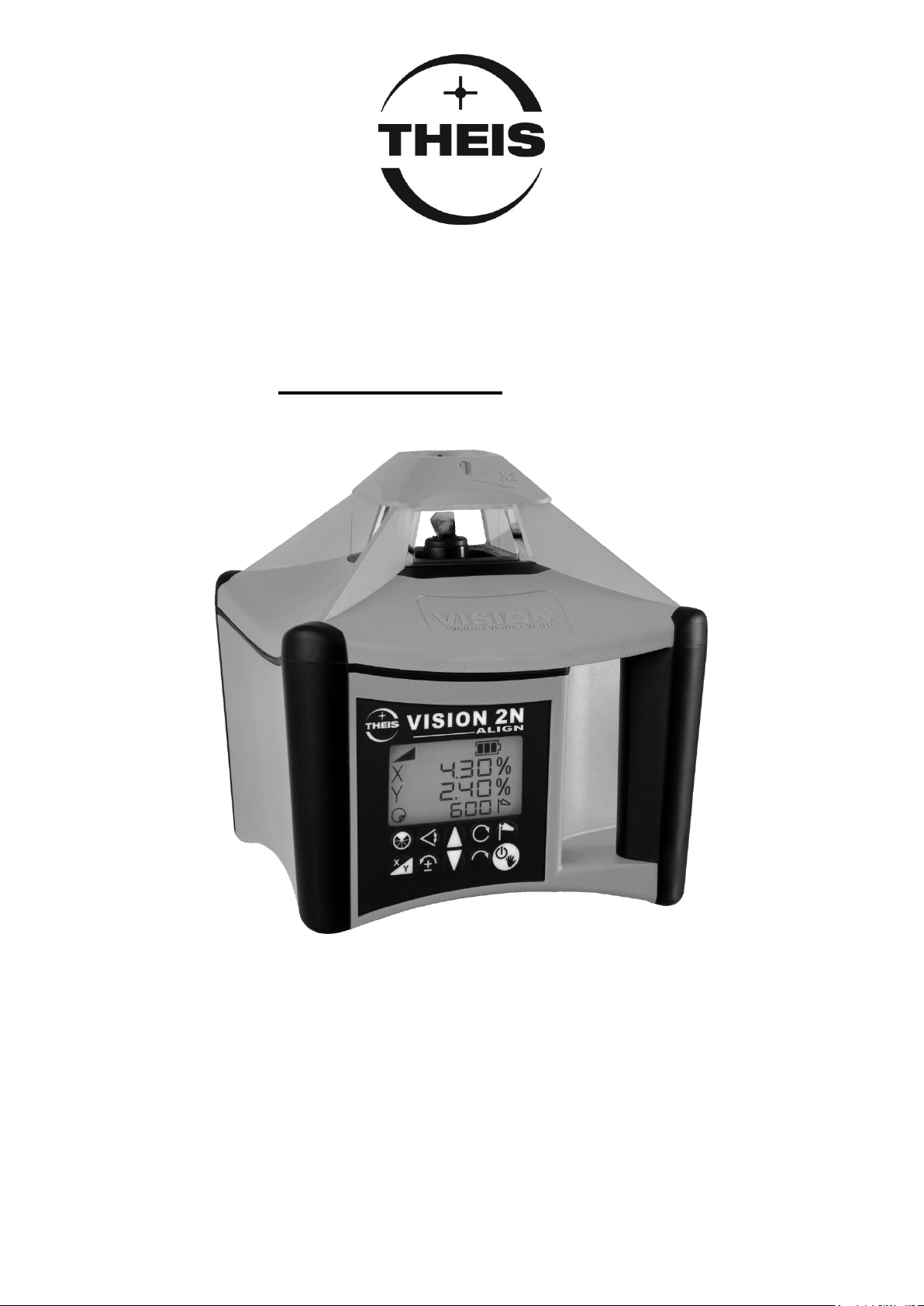
VISION 2N
Gebrauchsanleitung
DE
Instruction manual
EN
Instructions de service
FR
ALIGN
Page 2

Inhaltsverzeichnis
Vorwort..............................................................................................5
Tastaturbelegung / Display ...............................................................6
1. Horizontalbetrieb .......................................................................7
2. Vertikalbetrieb / Modus Fluchten ..............................................7
3. Rotationsgeschwindigkeit .........................................................8
4. Neigung.....................................................................................8
5. Neigung im Vertikalbetrieb ........................................................9
6. Neigung im manuellen Modus ................................................10
7. Ausblend - Modus ...................................................................11
8. Scan-Modus ............................................................................11
9. Einstellung der Nivellier-Empfindlichkeit (Windy) ...................12
10. TILT-Funktion..........................................................................12
11. Stromversorgung – Laser .......................................................13
12. Funk-Fernbedienung FB-V (Option) .......................................14
13. Empfänger TE 90 ALIGN ........................................................16
13.1 Tastaturbelegung .............................................................16
13.2 Standardbetrieb ................................................................17
13.3 Stromversorgung – Empfänger ........................................19
14. ALIGN – Funktion ...................................................................20
14.1 ALIGN – Horizontal ..........................................................20
14.1.1 Aufbau / Ablauf .........................................................20
14.1.2 Bedienung / Anzeige .................................................21
14.1.2.1 Neigung in Y – Achse (Abbildung 1) .................21
14.1.2.1 Neigung in Y – und X - Achse (Abbildung 1) ....22
14.2 ALIGN – Vertikal (Fluchten) .............................................24
14.2.1 Aufbau / Ablauf .........................................................24
14.2.2 Bedienung / Anzeige .................................................25
14.3 Störungsanzeigen ............................................................26
15. Paarung von Laser und Empfänger ........................................27
16. Überprüfung der Justierung ....................................................29
17. Menü .......................................................................................29
2
Page 3

18. Lieferumfang ........................................................................... 32
19. Betriebsanzeigen und Störungen ........................................... 32
20. Garantie .................................................................................. 32
21. Kurzanleitung ohne ALIGN ..................................................... 33
22. Technische Daten................................................................... 34
23. Lieferantenerklärung / Sicherheitshinweise ............................ 35
24. Entsorgung ............................................................................. 36
3
Page 4

4
Page 5

Gebrauchsanleitung
DE
Vorwort
VISION 2N ALIGN
...für den Profi am Bau.
Der Rotationslaser THEIS VISION 2N ALIGN setzt Maßstäbe im
Bereich der vollautomatischen Profilaser.
Er ist das Ergebnis langjähriger Erfahrung und innovativer Technik.
Der qualitativ hochwertige Baulaser zeichnet sich durch Robustheit
sowie höchster Präzision aus - Made in Germany - und sollte auf
keiner Baustelle fehlen.
Damit Sie stets ein einsatzbereites Gerät haben, sind folgende
Hinweise zu beachten:
1. Das Gerät niemals nass im Behälter aufbewahren.
2. Genauigkeit vor jedem Einsatz überprüfen, da wir keine Haftung
für Dejustierung übernehmen können.
3. Hinweise zur Behandlung des Akkus beachten.
4. Laser-Austritt-Fenster und Sensor-Fenster des Empfängers
(Option) schonend behandeln.
5
Page 6
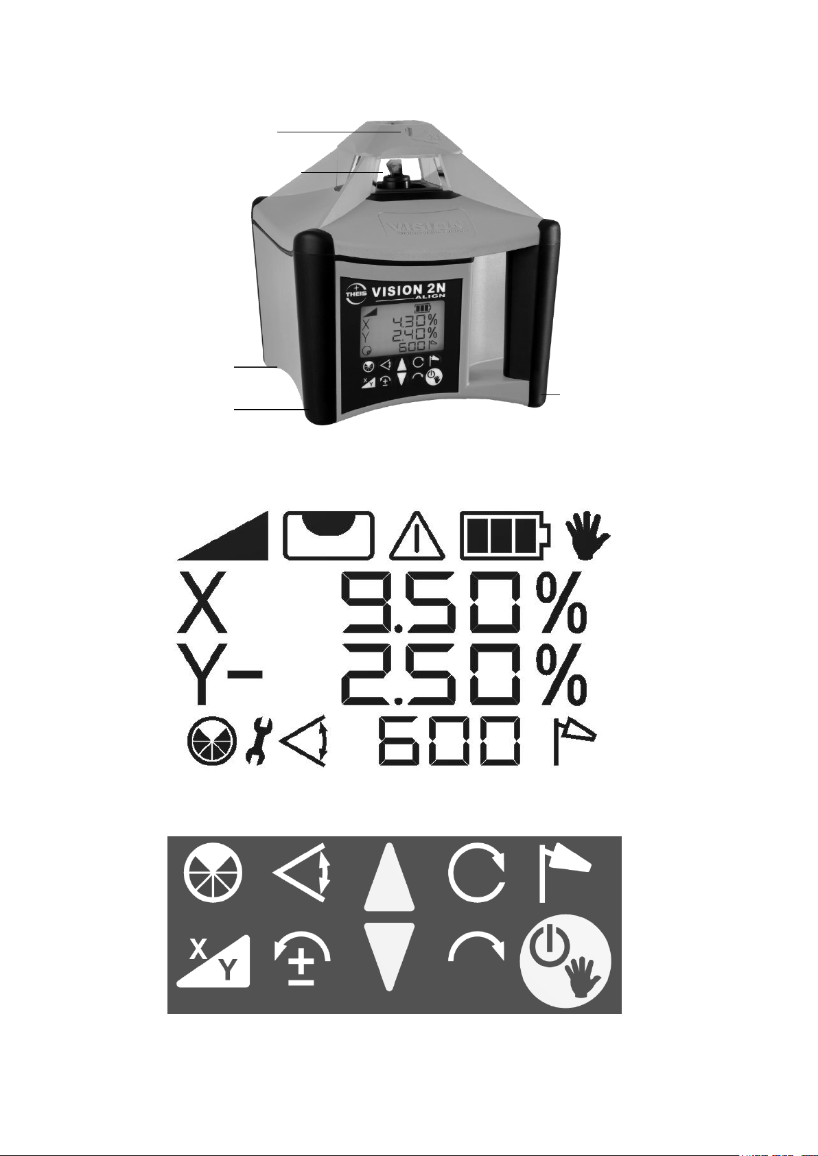
Tastaturbelegung / Display
X /Y-
Achs -
Neigung
Störung
Scan
Neigung
Ausblenden
Neigung
X/Y-Achse
Linksdrehung
Schrittbetrieb,
Ziffern -u. Vorzeichenwahl
Neigung
Fluchten
Rechtsdrehung
Schrittbetrieb,
Ziffernwahl
Ein/Aus,
manueller
Modus
Windy
Drehzahl oder
Scan beenden
Laseraustritt - Rotation
Ladebuchse
Manueller
Modus
Nivellieranzeige
Endanschlag ,
Lageänderung
Batterieanzeige
Akkufach
Optisches Visier
Produktinfos (Rückseite)
Via QR-Code u.a.
Gebrauchsanleitung
A
6
Page 7
1. Horizontalbetrieb
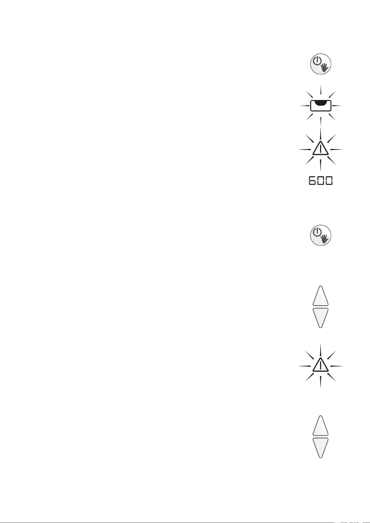
Stativ ausrichten und VISION mit Stativschraube fest
anziehen. Die Ausrichtgenauigkeit beeinflusst die Größe
des Neigungsbereichs. Mit Ein/Aus-Taste das Gerät
einschalten.
Es blinkt die Nivellieranzeige im beleuchteten Display.
Falls der Stativkopf stärker als 5° geneigt ist, wird dies
nach kurzer Zeit durch schnelles Blinken des Laserstrahls und des Alarm-Symbols angezeigt.
In diesem Fall das Gerät ausschalten und Stativ sorgfältiger ausrichten.
Nachdem der Horizontiervorgang beendet ist, beginnt
der Laserstrahl zu rotieren.
2. Vertikalbetrieb / Modus Fluchten
Laser so aufstellen bzw. auf dem Stativ befestigen,
dass die Tastatur nach oben zeigt. Mit der hinteren 5/8“
– Mutter ggf. auf dem Stativ anschrauben. Laser mit der
Ein-/Aus-Taste einschalten. Weitere Informationen siehe unter Punkt 1.
Zum Fluchten die Pfeiltasten drücken und damit den
Laserstrahl ausrichten. Wird die Pfeiltaste gedrückt gehalten, beschleunigt sich die Bewegung des Laserstrahls.
Wird beim Ausrichten der Verfahrweg überschritten,
wird dies durch die veränderte Balkenanordnung, ein
schnell blinkendes Warnsymbol und den schnell blinkenden Laserstrahl angezeigt.
Die Endanschläge können über die Pfeiltasten wieder
frei gefahren werden.
_ _ _
_ - _
-
_ -
7
Page 8
3. Rotationsgeschwindigkeit
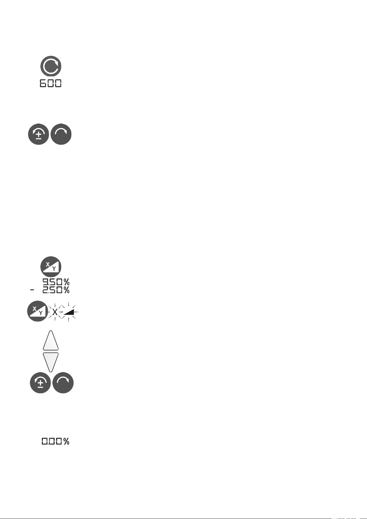
Die Rotationsgeschwindigkeit lässt sich in 4 Stufen regulieren: 0, 200, 600 und 800 U/min. Nach zweimaligem Drücken der Rotationstaste hält der Laser an
(Drehzahl 0). Durch weiteres Drücken der Taste wird
die Rotationsgeschwindigkeit jeweils erhöht.
Im Stillstand kann der Laserpunkt mit den Tasten
Links-/Rechtsdrehung bewegt werden. Wird eine der
Tasten gedrückt gehalten, beschleunigt sich die Bewegung des Laserpunktes.
4. Neigung
Der Laser kann – bei guter Stativausrichtung – in 2
Achsen von -10% bis +10% geneigt werden
Dazu den Laser zunächst mit dem optischem Visier
exakt auf Zielpunkt ausrichten und dann die Neigungswerte wie folgt eingeben:
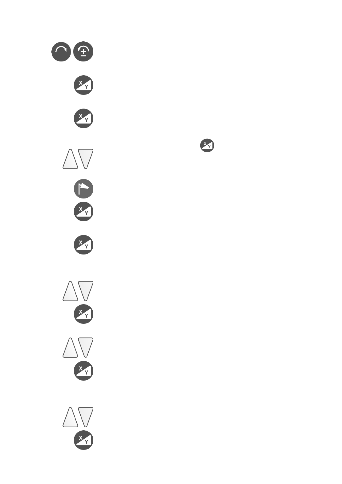
1-ter Tastendruck: Neigungsbetrieb wird aktiviert. Gespeicherte Neigungswerte der letzten Anwendung
werden angezeigt und automatisch angefahren.
2-ter Tastendruck: X, Neigungsanzeige und 1 Ziffer
Neigungswert blinken im Display.
Neigungswert mit den Pfeiltasten einstellen. Die jeweils
blinkende Ziffer kann verändert werden.
Zur nächsten Stelle gelangt man mit den Tasten Links/Rechtsdrehung. Für Änderung des Vorzeichens (±)
die linke Taste verwenden. Plus wird nicht angezeigt.
Bei lang anhaltendem Drücken der Pfeiltasten verändert sich der Wert mit zunehmender Beschleunigung.
Durch gleichzeitiges Drücken der Pfeiltasten wird die
Anzeige auf 0 zurückgesetzt.
8
Page 9
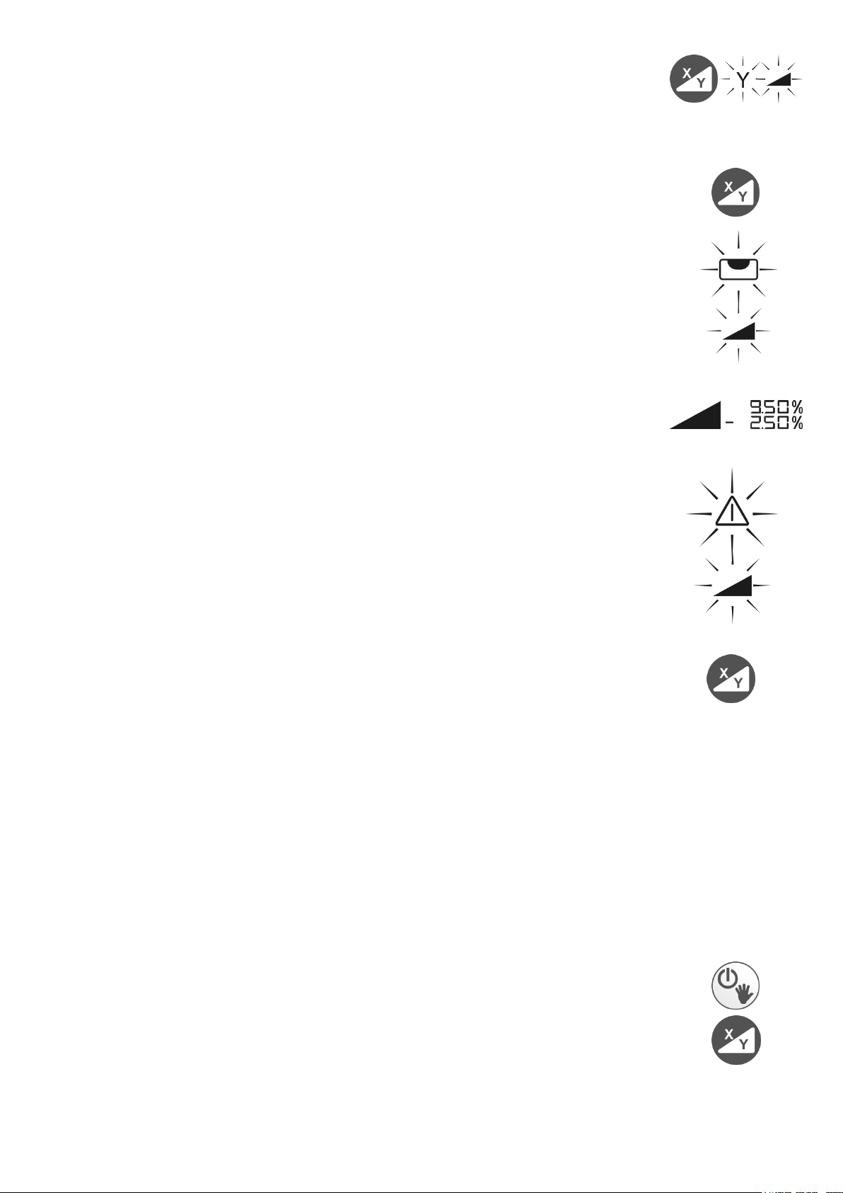
3-ter Tastendruck: Y, Neigungsanzeige und 1. Ziffer
Neigungswert blinken im Display.
Neigung der Y-Achse kann jetzt sinngemäß wie bei der
X-Achse eingestellt werden.
4-ter Tastendruck: Bestätigung der Eingabe
Danach beginnt zunächst eine erneute Nivellierung, an-
gezeigt durch die blinkende Nivellieranzeige im Display.
Anschließend werden die eingegebenen Neigungswerte
angefahren. Während dieses Vorgangs blinkt das Neigungssymbol.
Sind die Werte erreicht, werden die Neigungswerte und
das Neigungssymbol dauerhaft angezeigt.
Falls sich das Gerät durch äußere Einwirkungen wie Erschütterungen oder starke Temperaturunterschiede in
seiner Lage verändert, wird der Rotationsbetrieb automatisch unterbrochen. Dadurch werden Fehlmessungen
vermieden. Der Laserstrahl, das Neigungssymbol und
die Warnanzeige im Display blinken schnell.
Durch erneutes Drücken der Neigungstaste kann der
Neigungsbetrieb wieder aktiviert werden, das Gerät nivelliert wieder ein und die gespeicherten Neigungswerte
werden neu angefahren.
Achtung: Es kann sich die Aufstellposition des Lasers verändert haben und damit ggf. die Höhe und
die Richtung. Zur Sicherheit deshalb das Gerät aus
– und wieder einschalten und neu einregeln lassen.
5. Neigung im Vertikalbetrieb
Vermessungsaufgaben mit Neigung sind auch im Vertikalbetrieb möglich. Dazu Gerät vertikal aufstellen.
Einschalten und X/Y-Taste drücken.
Weitere Vorgehensweise sinngemäß wie unter Pkt. 4
beschrieben. Neigung nur in Y-Achse möglich.
9
Page 10
X
Y
6. Neigung im manuellen Modus
Um beispielsweise größere Neigungen unter Zuhilfenahme eines Winkeltisches einstellen zu können, oder
um bauseits vorgegebene Neigungen aufzunehmen,
muss die Automatik des Gerätes ausgeschaltet werden.
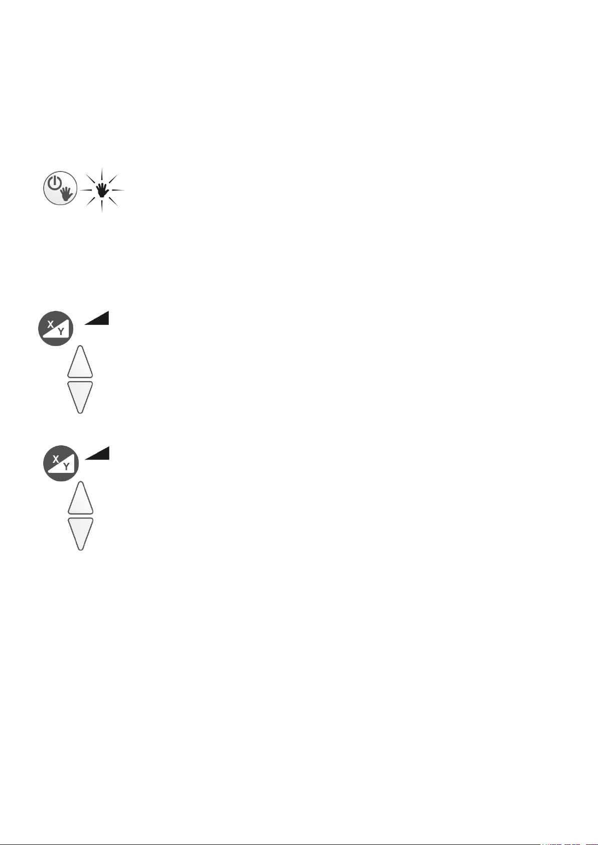
Dies geschieht durch langen Tastendruck der Ein-/AusTaste (ca. 5 Sek). Diese Funktion ist auch im Vertikalbetrieb verfügbar. Hinweis im Display durch blinkende
Hand.
Nun zunächst Laser mit Zielfernrohr oder optischem Visier exakt auf Zielpunkt ausrichten und dann die Neigung eingeben:
1-ter Tastendruck: Neigungssymbol und X werden im
Display angezeigt.
Mit den Pfeiltasten die Neigung eingeben.
2-ter Tastendruck: X- Symbol verschwindet und Neigungssymbol sowie Y werden im Display angezeigt.
Mit den Pfeiltasten die Neigung für Y eingeben.
Bei MINUS-Neigungen (Pfeil unten drücken) wird ein (-)
Minus im Display angezeigt. Bei oberer Pfeiltaste (Plus)
gibt es keine entsprechende Anzeige im Display.
Achtung: Im manuellen Modus keine automatische
Selbstnivellierung und keine Abschaltung des La-
sers!
10
Page 11
7. Ausblend - Modus
Im Ausblendmodus kann der Laseraustritt auf eine bestimmte Größe und Position gebracht werden. Dies ist
nur bei rotierendem Laserstrahl möglich.
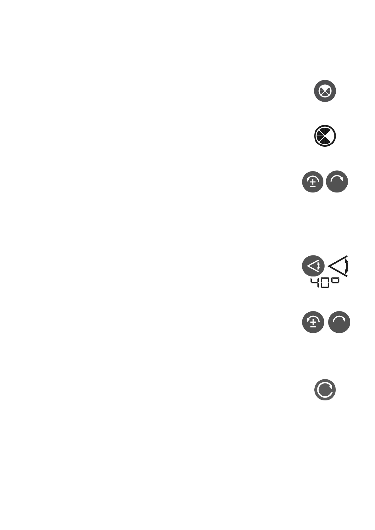
Durch 1x Drücken wird die kleinste Ausblendmöglichkeit
aktiviert, durch weiteres Drücken vergrößert sich der
Ausblendbereich. Mit dem 4 - ten Tastendruck wird der
Ausblendmodus wieder verlassen.
Der ausgeblendete Bereich wird im Display dunkel dargestellt. In dem hellen Bereich ist der Laserstrahl weiterhin sichtbar.
Mit den Tasten Links-/Rechtsdrehung kann der Ausblendbereich in die gewünschte Richtung gedreht werden.
8. Scan-Modus
Durch Drücken der Scan-Taste gelangt man in den
Scan-Modus, mit der kleinsten Einstellung von 10°.
Durch weiteres Drücken der Taste können 5 verschiedene Größen einer Laserlinie erzeugt werden (10°, 20°,
40°, 60°, 80°); diese werden im Display angezeigt.
Mit den Tasten Links-/Rechtsdrehung kann man die Laserlinie entsprechend verfahren. Wird eine Taste gedrückt gehalten, beschleunigt sich die Bewegung der
Laserlinie.
Beim Verlassen des Scanmodus mit der Rotationstaste
wird die letzte Position des Rotorkopfes gespeichert.
Wird also zu einem späteren Zeitpunkt erneut der
Scanmodus gewählt, fährt die Laserlinie an diese Position.
11
Page 12

9. Einstellung der NivellierEmpfindlichkeit (Windy)
Falls während der Arbeit durch Wind, Bodenschwingungen oder leichte Stöße die Rotation immer wieder unterbrochen wird, weil das Gerät nachregeln muss, besteht die Möglichkeit, über die Windy-Funktion hier Abhilfe zu schaffen.
Durch Drücken der Windy – Taste, wird die Nivellierempfindlichkeit des Instrumentes etwas herabgesetzt.
Die Windy – Taste ist im Neigungsmodus gesperrt.
10. TILT-Funktion
Bei größeren Veränderungen der Aufstellposition (z. B.
versehentliches Verstellen des Stativbeins), sorgt eine
sogenannte TILT-Funktion dafür, dass sich das Gerät
abschaltet und dies durch schnelles Blinken des Laserstrahls und des Warndreiecks meldet.
Anschließend muss das Gerät neu gestartet werden
12
Page 13
11. Stromversorgung – Laser
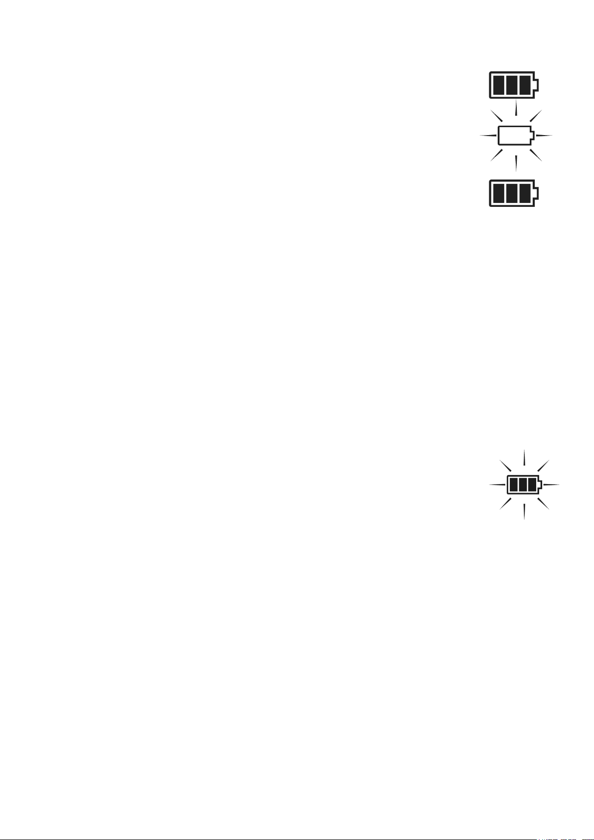
Die Kapazitätsanzeige des Akkus zeigt den Zustand des
Akkus in 4 Stufen an.
Wenn die 3 Balken in der Anzeige leer sind und der äußere Rahmen blinkt, ist die Kapazität erschöpft und der
Akku muss geladen werden. Wird dies nicht beachtet,
schaltet das Gerät nach einiger Zeit automatisch ab.
Während des Ladevorgangs blinken die 3 Balken aufsteigend. Wenn der Akku voll ist, werden alle Balken angezeigt.
Nachladen des Akkus bei Raumtemperatur nur mit
THEIS Standard-Netzgerät über die Ladebuchse unterhalb des Lasers. Das Laden unter +5°C kann zu einem
Defekt der Akkus führen.
Ein Nachladen ist auch während des Betriebs möglich.
Ein Überladen ist nicht möglich.
Ladegerät nur in trockenen Räumen einsetzen!
Die eingesetzten Akkus mit Eneloop™-Technologie
bieten den Vorteil einer geringen Selbstentladung.
Somit ist ein Nachladen der Akkus bei Nichtbenutzung des Gerätes frühestens alle 6 Monate nötig.
Im Akkufach können auch normale Alkaline MonoZellen verwendet werden. Diese dürfen auf keinen Fall
geladen werden. Falls dies doch versehentlich geschieht, blinkt Batteriesymbol.
Achtung: Auf richtige Polung achten. Symbole ±
sind im Batteriefach am Boden angebracht. Entsor-
gungshinweise Pkt. 24 beachten.
Achtung: Da die Batteriepole und - kontakte über die Zeit
verschmutzen können und es dadurch Kontaktprobleme
geben kann, ist eine regelmäßige Überprüfung und ggf. eine
Reinigung mit einem weichem Tuch und Reinigungsmittel
(Spiritus, Alkohol) nötig.
13
Page 14
12. Funk-Fernbedienung FB-V (Option)
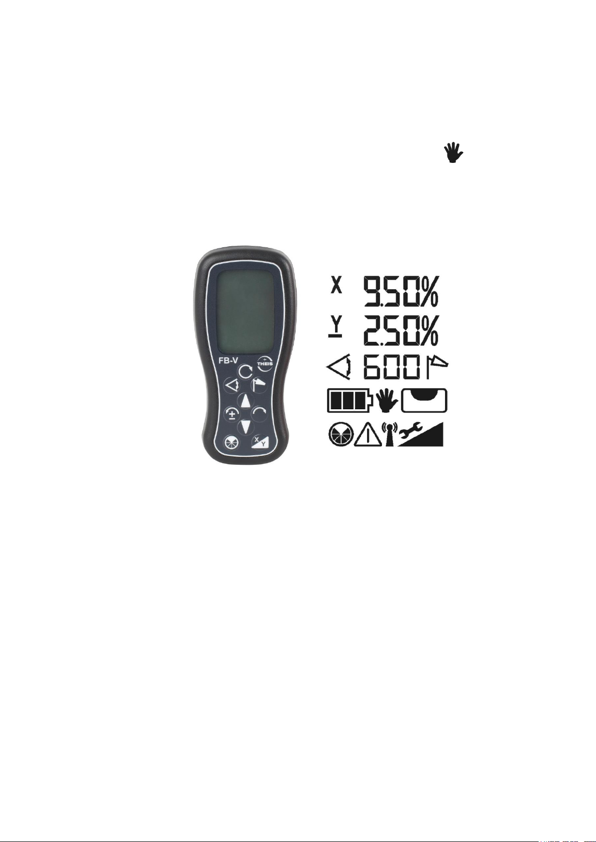
Die Funk-Fernbedienung ist bidirektional konzipiert. Alle Informationen die im Display des Lasers angezeigt werden, finden
sich auch im beleuchteten Display der Fernbedienung wieder.
Die Tastensymbole auf dem Bedienfeld, entsprechen den Tas-
ten auf der Lasertastatur. Die Betriebsart MANUELL fehlt,
um eine versehentliche Eingabe dieser Funktion zu unterbinden.
Die FB-3 durch Drücken einer beliebigen Taste einschalten. Die
Die FB-V durch Drücken einer beliebigen Taste einschalten.
Die Fernbedienung sucht sich automatisch einen passenden
Kanal, um auszuschließen, dass es zu Störungen mit anderen
Geräten kommt.
Im Display finden sich die gleichen Angaben wieder wie auf dem
Display des dazugehörigen Lasers. Ist dies nicht der Fall und
wird stattdessen ein Antennensymbol angezeigt, kann dies folgende Gründe haben:
- Der Laser ist nicht eingeschaltet
- Der Radiokanal ist nicht korrekt eingestellt
- Die Fernbedienung befindet sich außer Reichweite zum Laser.
Durch gleichzeitiges Drücken der beiden Pfeiltasten kann der Laser
ausgeschaltet werden. Die FB-V schaltet sich nach 1 Minute selbstständig aus.
14
Page 15

Ist die Standby-/ Sleep-Funktion am Laser aktiviert, um die Akkukapazität zu schonen (siehe Kapitel 17), lässt sich durch gleichzeitiges Drücken der beiden Pfeiltasten an der FB-V, der Laser in den
Standby versetzen. Mit einer beliebigen Taste an der FB-V kann
der Standby-Modus beendet werden und das Gerät kehrt in den
Normalbetrieb zurück, wie nach dem erneuten Einschalten des Gerätes. Die maximale Standby-Zeit lässt sich im Info-Menü einstellen
(siehe Kapitel 17). Wird die Standby-Zeit überschritten schaltet sich
der Laser aus.
Die Stromversorgung erfolgt über zwei Alkaline Mikro AAA Batterien. Die Betriebsdauer beträgt ca. 60 Stunden.
Das Batterie-Symbol zeigt den Batteriezustand der FB-V an.
Zum Wechsel der Batterien Deckel auf der Rückseite öffnen und
Austausch vornehmen. Auf richtige Polung achten. Entsorgungshinweise siehe Pkt. 24.
15
Page 16
13. Empfänger TE 90 ALIGN
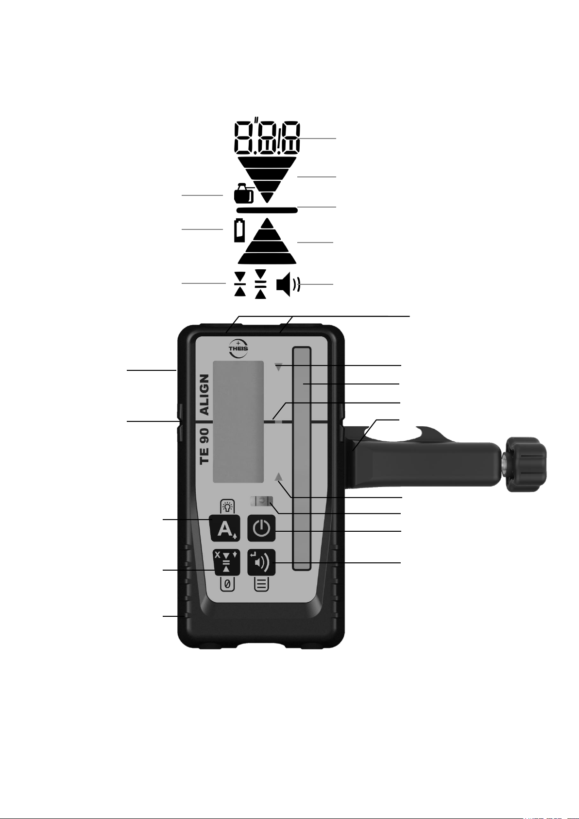
LED Richtungsanzeige
LED Zentrum
Sensorfenster
LED Richtungsanzeige
Röhrenlibelle
Taste An / Aus
Taste akustisches Signal /
Menü: Eingabetaste
Magnet
Display
(auch Rückseite)
Kerbe Zentrum
Taste:
Kurz: Align Ein/Aus
Lang: LEDs Ein/Aus
Menü: Pfeiltaste oben
Taste:
Kurz: Anzeigegenauigkeit
Lang: Referenzmarke
ALIGN Horiz.: X - Achse
Menü: Pfeiltasten unten
Befestigungsklammer
Anzeigegenauigkeit
Batterieanzeige
Anzeige akustisches Signal
Pfeil für Bewegungsrichtung
Zentrum Balken
Pfeil für Bewegungsrichtung
Numerische - / Textanzeige
Batteriefach (Rückseite)
Gerätesymbol:
Mit Laser verbunden
13.1 Tastaturbelegung
16
Page 17

13.2 Standardbetrieb
mm
cm
Zoll
Zoll/Bruch
Display
Sehr fein
0.5
0.05
0.02
-
blinkend
Fein
1.0
0.1
0.05
1/8
dauerhaft
Mittel
2.0
0.2
0.1
1/4
dauerhaft
Grob
5.0
0.5
0.2
1/2
dauerhaft
Sehr grob
10.0
1.0
0.5
-
blinkend
Ein- und Ausschalten des Gerätes
Drücken Sie die Taste An / Aus
Anpassen der Lautstärke
Durch langes Drücken der Taste akustisches Signal kann die Lautstärke angepasst werden: Leise / Laut / Aus
Laut: Lautsprecher-Symbol wird dauerhaft angezeigt; Anzeige
“Hi” für eine Sekunde
Leise: Lautsprecher-Symbol wird dauerhaft angezeigt; Anzeige
“Low” für eine Sekunde
Aus: Lautsprecher-Symbol wird nicht angezeigt;
Anzeige “OFF” für eine Sekunde
Einstellen der Anzeigengenauigkeit
Einmal die Taste Anzeigegenauigkeit drücken, um die aktuelle Einstellung auf dem Display zu sehen. Drücken Sie, solange der Wert
angezeigt wird (innerhalb einer Sekunde), erneut, um die Genauigkeit zu ändern. Drücken Sie so oft, bis die gewünschte Einstellung
erscheint.
Tabelle 1: Genauigkeit
LEDs aktivieren / deaktivieren
Die Taste LED – Anzeige drücken, um die LED-Anzeige zu ändern.
Ist die Option aktiv, werden die Messwerte, zusätzlich zur Displayanzeige, auch über die LEDs angezeigt.
17
Page 18

Benutzerdefinierte Sollhöhe
Sie können, innerhalb von -10 und +40 mm um die Zentrumskerbe,
eine beliebige Sollhöhe (Nullpunkt festlegen). Dazu halten Sie während des Laserempfangs die Taste Anzeigegenauigkeit für zwei
Sekunden gedrückt. Bei Erfolg hören Sie einen Bestätigungston
und ein asymmetrisches Pfeil-Symbol erscheint im Display. Befindet sich der Laserstrahl außerhalb des erlaubten Bereiches, ist ein
Fehlerton zu hören und das Display zeigt den Fehler E30. Um die
Sollhöhe zurückzusetzen, halten Sie die Taste Anzeigegenauigkeit,
während kein Laserempfang besteht, für zwei Sekunden gedrückt.
Beim Ausschalten des Gerätes wird die Sollhöhe automatisch zurückgesetzt.
Benutzung des Menüs
Mit der Menüfunktion können verschiedene Einstellungen geändert
werden. Für die meisten Anwendungen sind die Standardeinstellungen die beste Wahl. Wir empfehlen, die Einstellungen nur für
spezielle Anwendungen zu ändern.
Drücken Sie die Taste akustisches Signal / Eingabetaste mehr
als zwei Sekunden, um in das Menü zu gelangen.
Menüeinträge (z. B. SEn) werden dauerhaft dargestellt und kön-
nen mit den Menü-Pfeiltasten durchgeblättert werden.
Menüeinträge werden durch Drücken der Taste akustisches Sig-
nal / Eingabetaste ausgewählt.
Optionen (z. B. On) werden blinkend dargestellt und können mit
den Menü-Pfeiltasten geändert werden.
Verlassen Sie das Menü durch Drücken der Taste An / Aus.
Menüeinträge:
SEn - Empfindlichkeit: Hoch (Hi) / Niedrig (Low)
Standard: Hoch. Bei Problemen mit Störungen wie z.B. Leuchtstoff-
röhren und Blitzlichtern kann es helfen, die Einstellung auf Niedrig
zu setzen.
AvG - Mittelung: Hoch (Hi) / Niedrig (Low)
Standard: Niedrig. Setzen Sie die Einstellung auf Hoch, wenn sie
stabilere Werte unter schwierigen atmosphärischen Bedingungen
benötigen.
18
Page 19

Unt - Maßeinheit: mm / cm / Zoll (in) / Zoll in Brüchen (f.in)
Standard: mm. Wählen Sie die gewünschte Maßeinheit aus.
o.o.b - Verlust des Laserstrahls: An (On) / Aus (OFF)
Standard: Aus. Schaltet die Anzeige für den Verlust des Laser-
strahls an und aus. Eine Pfeilsequenz zeigt an, dass der Laser den
Empfangsbereich verlassen hat. Der Pfeil gibt an, in welche Richtung das Gerät bewegt werden muss, um den Laserstrahl wiederzufinden.
Inf - Geräteinformationen
Hier finden Sie Informationen über die Gerätesoftware (Fw), den
Gerätetyp (dc) und die Seriennummer (Sn).
ALG – Empfängerausrichtung bei ALIGN - Funktion
Standard: "Hor" "UP" / "Ver" "UP". Einstellungen “UP” und
“dwn” möglich.
Einstellung „UP“ horizontal: Schrift „THEIS“ in Logo aufrecht lesbar
Einstellung „UP“ vertikal: Schrift „TE 90 ALIGN“ aufrecht lesbar
HINWEIS: Alle Menüeinstellungen werden beim Ausschalten
des Empfängers gespeichert.
13.3 Stromversorgung – Empfänger
Wenn die Batterieanzeige auf dem Display erscheint, sollte die Batterie (1xAA) gewechselt werden, da sonst die Reichweite eingeschränkt sein kann.
Dazu das Batteriefach öffnen und den Austausch vornehmen.
Alte Batterie sachgemäß entsorgen (siehe Pkt. 24) und bei neuer
Batterie auf richtige Polung achten (siehe Symbole).
19
Page 20
14. ALIGN – Funktion
14.1 ALIGN – Horizontal
14.1.1 Aufbau / Ablauf
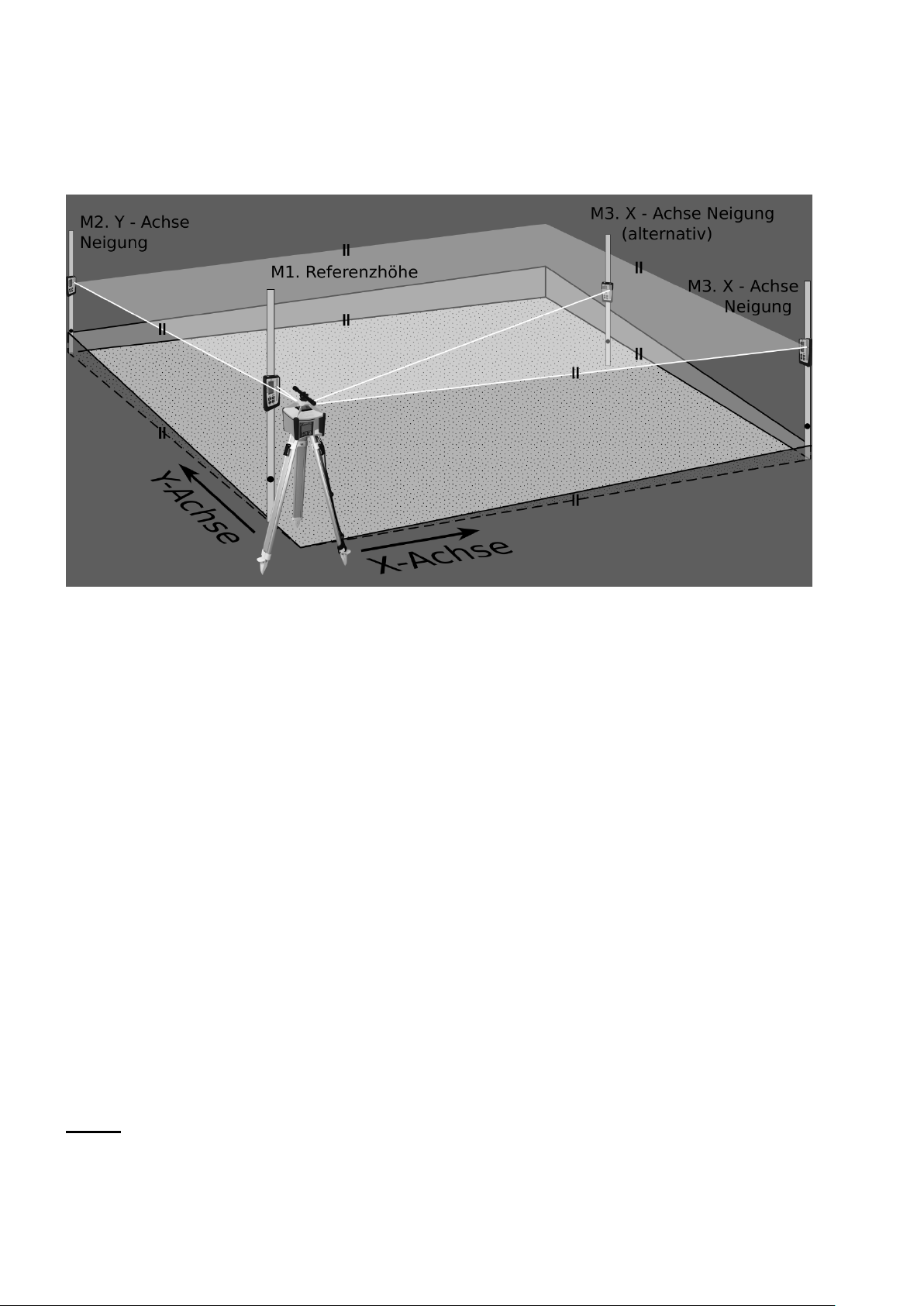
Abbildung 1: Aufbau ALIGN - Horizontal
Mit dem Laser-System Vision 2N ALIGN und dem Empfänger TE
90 ALIGN, können 2 Neigungen automatisch in der X- und Y - Ach-
se eingestellt werden.
Zunächst, wie unter Kapitel 4 beschrieben, den Stativkopf gut horizontal ausrichten und den Laser in Y-Richtung auf den ersten Zielpunkt M2 fluchtend einstellen (Abbildung 1). Wenn die ermittelten
Neigungswerte möglichst genau werden sollen, ist das Zielfernrohr
(Option) zu verwenden.
Danach die Lasermesslatte mit Empfänger in möglichst geringer
Entfernung zum Laser aufstellen (Abbildung 1: M1 Referenzhöhe)
und beide Geräte wie in den Kapiteln 1 und 13.2 beschrieben, einschalten und Empfängerzentrum auf Laserstrahlhöhe bringen.
Dieses Maß dient für die gesamte Messung als Referenzhöhe
und darf nicht mehr verändert werden!
Empfänger / Lasermesslatte am Zielpunkt M2 aufstellen und die
erste Neigung in der Y-Achse aufnehmen. (Siehe Abbildung 1)
20
Page 21
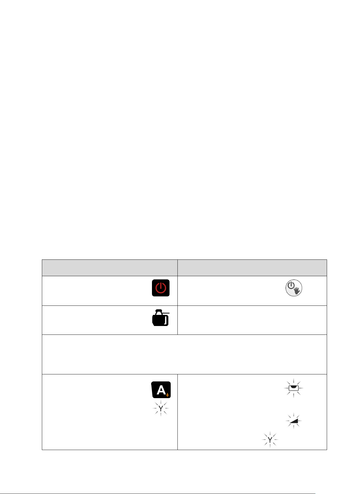
Achtung:
TE 90 ALIGN
VISION 2N ALIGN
Empfänger einschalten.
Laser einschalten.
Gerätesymbol muss
angezeigt werden.
Empfänger in kurzem Abstand vor Laser auf Referenzhöhe einstellen. Anschließend Empfänger auf Zielpunkt M2 bringen. M2 muss
exakt auf der Y-Achse liegen (Zielfernrohr empfohlen)
Y- Achse
Taste A kurz drücken.
ALIGN in Y-Achse
startet.
Laser fährt Endschalter an und
nivelliert.
Nivellierung beendet. Laser
sucht Empfänger.
0.00% A
Um genaue Neigungswerte zu erhalten, muss der erste Neigungsaufnahmepunkt exakt auf der Y-Achse des Lasers liegen. Dafür wird das bei THEIS erhältliche Fernrohr unbedingt
empfohlen.
Hinweise:
(1) Während der Empfängersuche kommt es zu Veränderungen
der Rotationsdrehzahl und der Ausblendbereiche.
(2) Es dürfen keine Störobjekte zwischen Laser und Empfänger
sein, sonst wird die Suchgeschwindigkeit beeinflusst und das
Finden erschwert.
(3) Wenn im ALIGN-Status ein zweiter normaler Empfänger ein-
gesetzt werden soll, um bespielweise Zwischenpunkte zu ermitteln, ist darauf zu achten, dass man mit diesem Empfänger
nicht das Empfangsfeld des TE 90 ALIGN abdeckt, sondern
darunter oder darüber bleibt. Dies könnte sonst zu einem fehlerhaften Ergebnis führen.
14.1.2 Bedienung / Anzeige
14.1.2.1 Neigung in Y – Achse (Abbildung 1)
21
Page 22
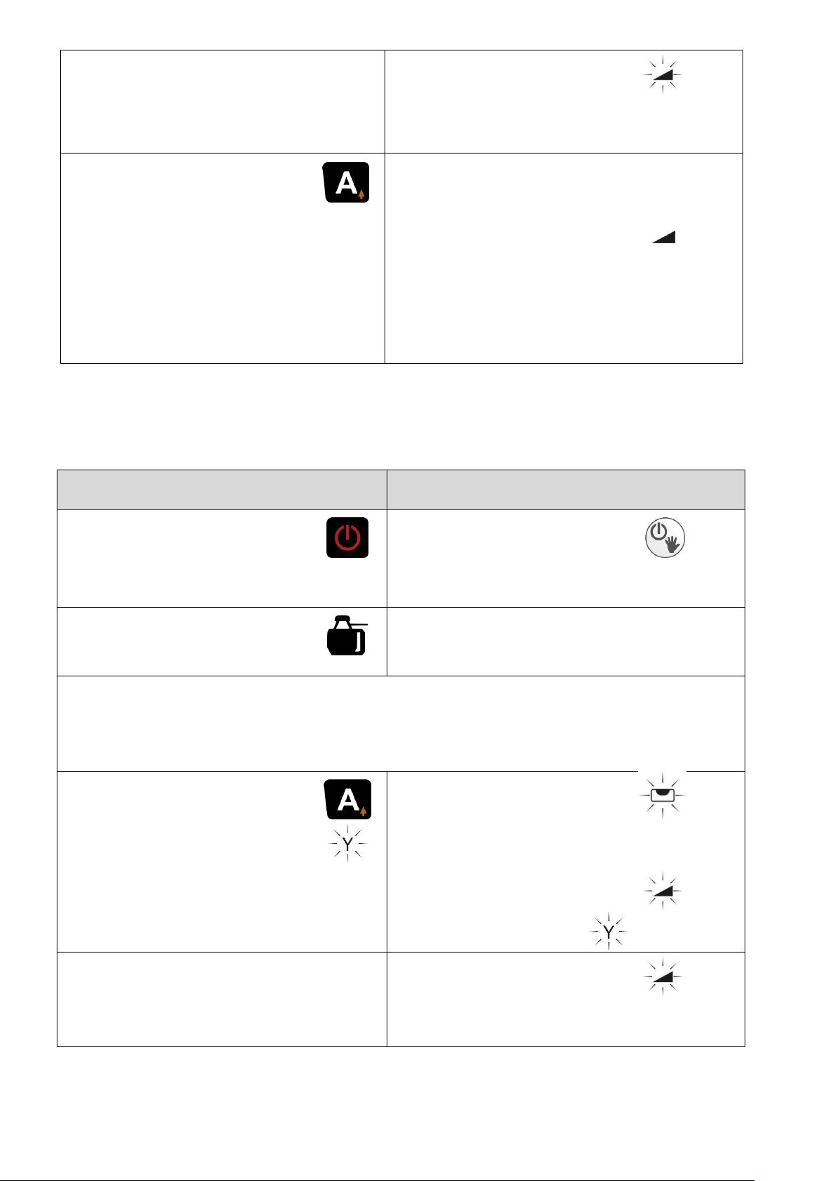
Tabelle 2: ALIGN-Funktion Horizontal nur Y-Achse
Suche abgeschlossen:
Y oder –Y und Neigungswert
_._ _ blinken im Wechsel.
Empfänger gefunden.
Y
_._ _% A
ALIGN beenden:
Taste A kurz drücken:
ALIGN deaktiviert.
Empfänger ist nun im
Standardbetrieb und
kann entfernt werden.
Empfänger - Verfolgung stoppt.
Neigungswert Y
gespeichert.
Laser in StandardNeigungsfunktion
Y
_._ _%
TE 90 ALIGN
VISION 2N ALIGN
Empfänger einschalten.
Laser einschalten.
Gerätesymbol muss
angezeigt werden.
Empfänger in kurzem Abstand vor Laser auf Referenzhöhe einstellen. Anschließend Empfänger auf Zielpunkt M2 bringen. M2 muss
exakt auf der Y-Achse liegen (Zielfernrohr empfohlen)
Y- Achse
Taste A kurz drücken.
ALIGN in Y-Achse startet.
Laser fährt Endschalter an und
nivelliert.
Nivellierung beendet. Laser
sucht Empfänger.
0.00% A
Suche abgeschlossen:
Y oder –Y und Neigungswert
_._ _ blinken im Wechsel.
Empfänger gefunden.
Y
_._ _% A
14.1.2.1 Neigung in Y – und X - Achse (Abbildung 1)
22
Page 23
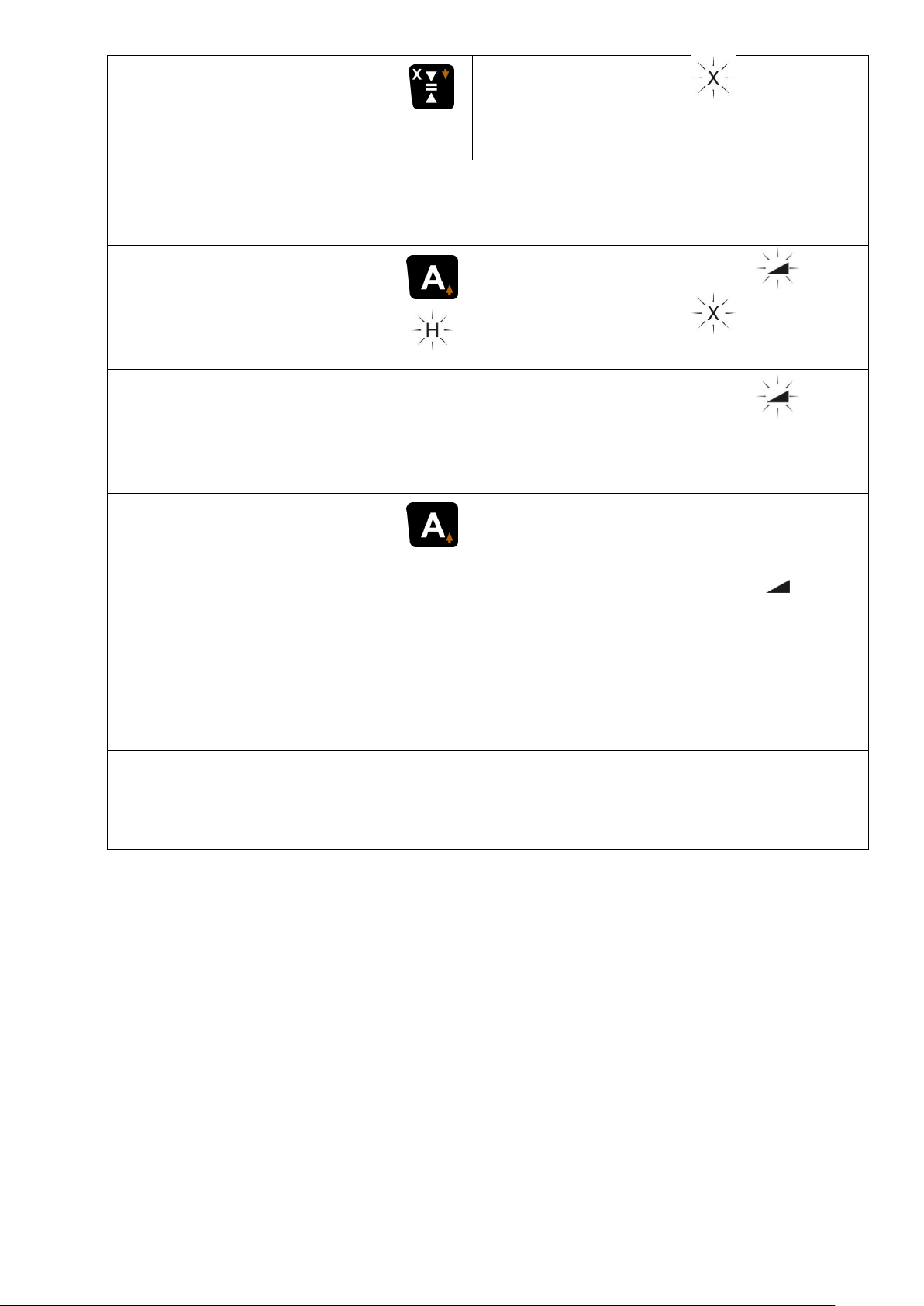
Tabelle 3: ALIGN-Funktion Horizontal Y- und X-Achse
X-Achse
Taste Anzeigegenauigkeit / X drücken
H
Neigungswert Y
wird gespeichert.
0.00%
Y
_._ _% A
Die Neigung in der Y-Achse wird nun nicht mehr nachgeregelt.
Empfänger auf Zielpunkt M3 für X – Neigung bringen.
Taste A kurz drücken:
ALIGN in X-Achse star-
tet.
Laser sucht Empfänger
0.00%
Y
_._ _% A
Suche abgeschlossen:
X oder –X (H oder –H) und
Neigungswert _._ _ blinken im
Wechsel.
Empfänger gefunden.
X
_._ _%
Y
_._ _% A
ALIGN beenden:
Taste A kurz drücken:
ALIGN deaktiviert.
Empfänger ist nun im
Standardbetrieb und
kann entfernt werden.
Empfänger - Verfolgung stoppt.
Neigungswert X
gespeichert.
Laser in StandardNeigungsfunktion.
X
_._ _%
Y
_._ _% A
Die Neigung wird nun in keiner Achse mehr nachgeregelt, aber
überwacht, um eine evtl. größere Veränderung der Lage des Lasers anzuzeigen. Siehe auch Kapitel 4 wegen Warnhinweisen.
Achtung: Wird versehentlich der Laser aus seiner Position
gebracht, muss die komplette Messung wiederholt werden.
23
Page 24
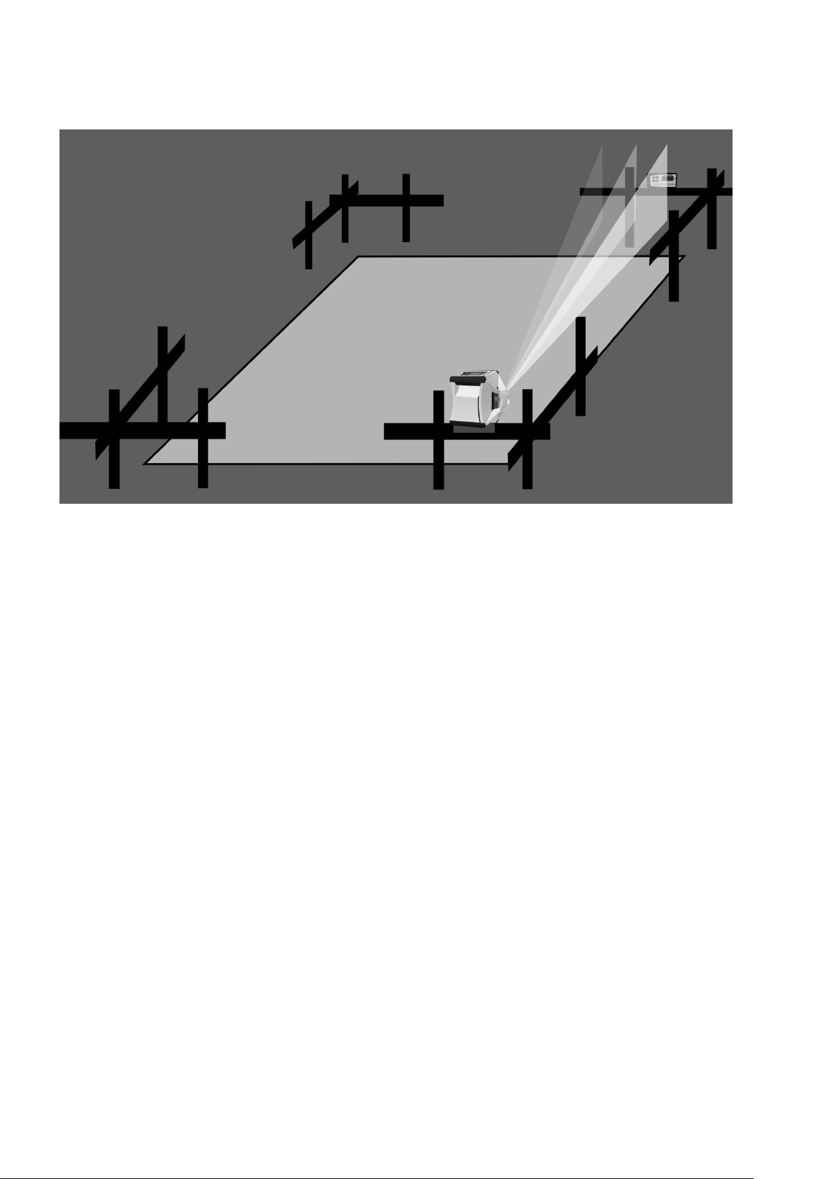
14.2 ALIGN – Vertikal (Fluchten)
14.2.1 Aufbau / Ablauf
Abbildung 2: ALIGN - Vertikal
Das Laser-System Vision 2N ALIGN mit dem Empfänger TE 90
ALIGN kann im Vertikalbetrieb auch zum Fluchten eingesetzt wer-
den.
Dazu wird der Laser wie unter Kapitel 2 beschrieben z. B. auf ein
Stativ, dem Boden oder ein Schnurgerüst angebracht. Im Folgenden wird das Anwendungsbeispiel Schnurgerüst erläutert.
Den Laser nach Abbildung 2 so aufstellen, dass im Nivelliermodus
die vertikale Laserebene über dem Nagel fluchtet.
Empfänger TE 90 ALIGN an dem gewünschten Zielpunkt positionieren. Den Empfänger so orientieren, dass der Schriftzug „TE 90
ALIGN“ aufrecht lesbar ist. (Die Orientierung des Empfängers kann
im Empfänger-Menü Seite 19 auch geändert werden).
Hinweise:
(1) Den Empfänger und den Laser mit möglichst großem Abstand
(mindestens 10 cm, besser 100 cm) zum Boden aufbauen. Je
größer der Abstand, desto größer die Funkreichweite. Der
Empfänger muss sich im Suchbereich des Lasers befinden (+/9°).
24
Page 25
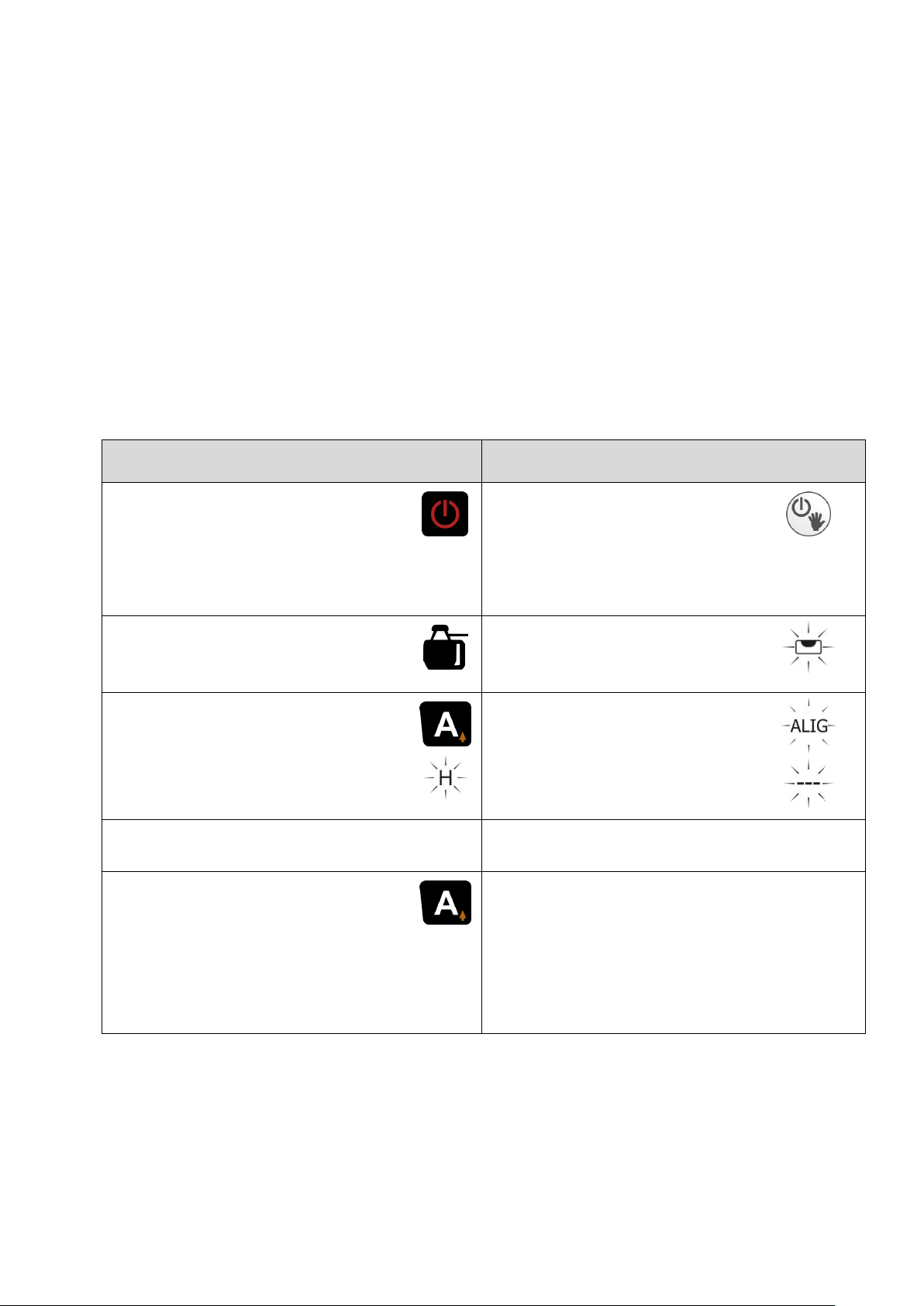
(2) Während der Empfängersuche kommt es zu Veränderungen
TE 90 ALIGN
VISION 2N ALIGN
Empfänger einschalten.
Empfängerorientierung:
Schriftzug TE 90 ALIGN
aufrecht lesbar
Laser einschalten.
Display nach oben
Gerätesymbol muss angezeigt werden.
Laser nivelliert.
Taste A kurz drücken.
ALIGN startet.
Laser sucht Empfänger.
Anzeige
H
Empfänger gefunden
ALIG
– – –
A kurz drücken:
ALIGN deaktiviert.
Empfänger ist im Standardbetrieb und kann entfernt werden.
Empfänger - Verfolgung stoppt.
Laser im Standardbetrieb verti-
kal.
der Rotationsdrehzahl und der Ausblendbereiche.
(3) Es dürfen keine Störobjekte zwischen Laser und Empfänger
sein, sonst wird die Suchgeschwindigkeit beeinflusst und das
Finden erschwert.
(4) Wenn im ALIGN-Status ein zweiter normaler Empfänger ein-
gesetzt werden soll, um bespielweise Zwischenpunkte zu ermitteln, ist darauf zu achten, dass man mit dies em Empfänger
nicht das Empfangsfeld des TE 90 ALIGN abdeckt, sondern
darunter oder darüber bleibt. Dies könnte sonst zu einem fehlerhaften Ergebnis führen.
14.2.2 Bedienung / Anzeige
Tabelle 4: ALIGN-Funktion Vertikal
25
Page 26
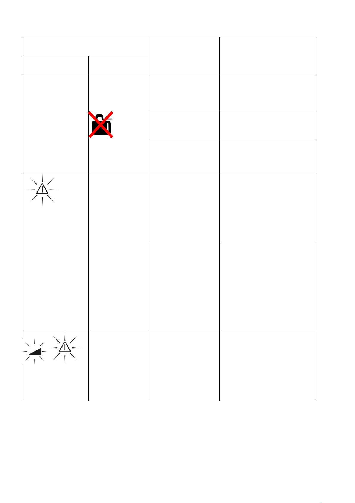
14.3 Störungsanzeigen
Anzeige
Fehler
Maßnahme
Laser
Empfänger
no Conn
A blinkt
Gerätesymbol
verschwindet
Keine Funkverbindung
Objekt zwischen Laser und Empfänger
entfernen
Empfänger
ausgeschaltet
Empfänger einschalten
Reichweite
überschritten
Empfänger näher
zum Laser bringen
ALIG FAIL
Rotorstopp
Laserstrahl
blinkt
Err
Falsche
Empfängerorientierung
Empfänger drehen
oder
Empfängerausrichtung über Empfänger-Menü Seite 19
ändern
max. Suchbereich von 15%
überschritten.
Horizontal:
Geländeneigung ist
zu groß. Messung
nicht möglich
Vertikal:
Laser besser ausrichten
Err
Laser wurde
versehentlich
angestoßen
Laser ausschalten
und Ausrichtung
überprüfen.
Messung komplett
neu starten
Tabelle 5: Fehlerbeschreibung
26
Page 27
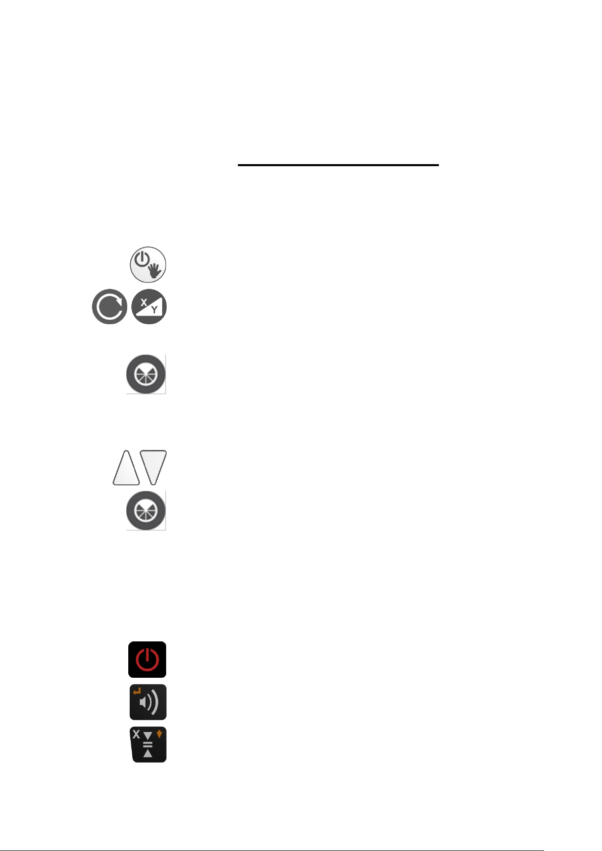
15. Paarung von Laser und Empfänger
Laser einschalten
5 Sekunden lang drücken
InFo
INFO- Anzeige
ca. 3 Sekunden drücken
ALIG
CHAn
ALIGN Kanalwahl
Kanal wählen 0 – 35.
Paarung starten
ALIG
PAIr
Anzeige blinkt, Laser wartet auf TE 90 ALIGN
Einstellungen TE90 ALIGN
Empfänger einschalten
ca. 3 Sekunden drücken bis sich das Menü öffnet
2x drücken
rdo
…erscheint im Menü
Achtung:
Die Paarung zwischen Laser und Empfänger ist werkseitig
vollzogen und sollte vom Anwender nur dann durchgeführt
werden, wenn mindestens zwei ALIGN-Systeme parallel zum
Einsatz kommen und dabei Störungen auftreten.
In diesem Fall muss die Frequenz von Laser und Empfänger
wie folgt angepasst werden.
Einstellungen Laser
27
Page 28
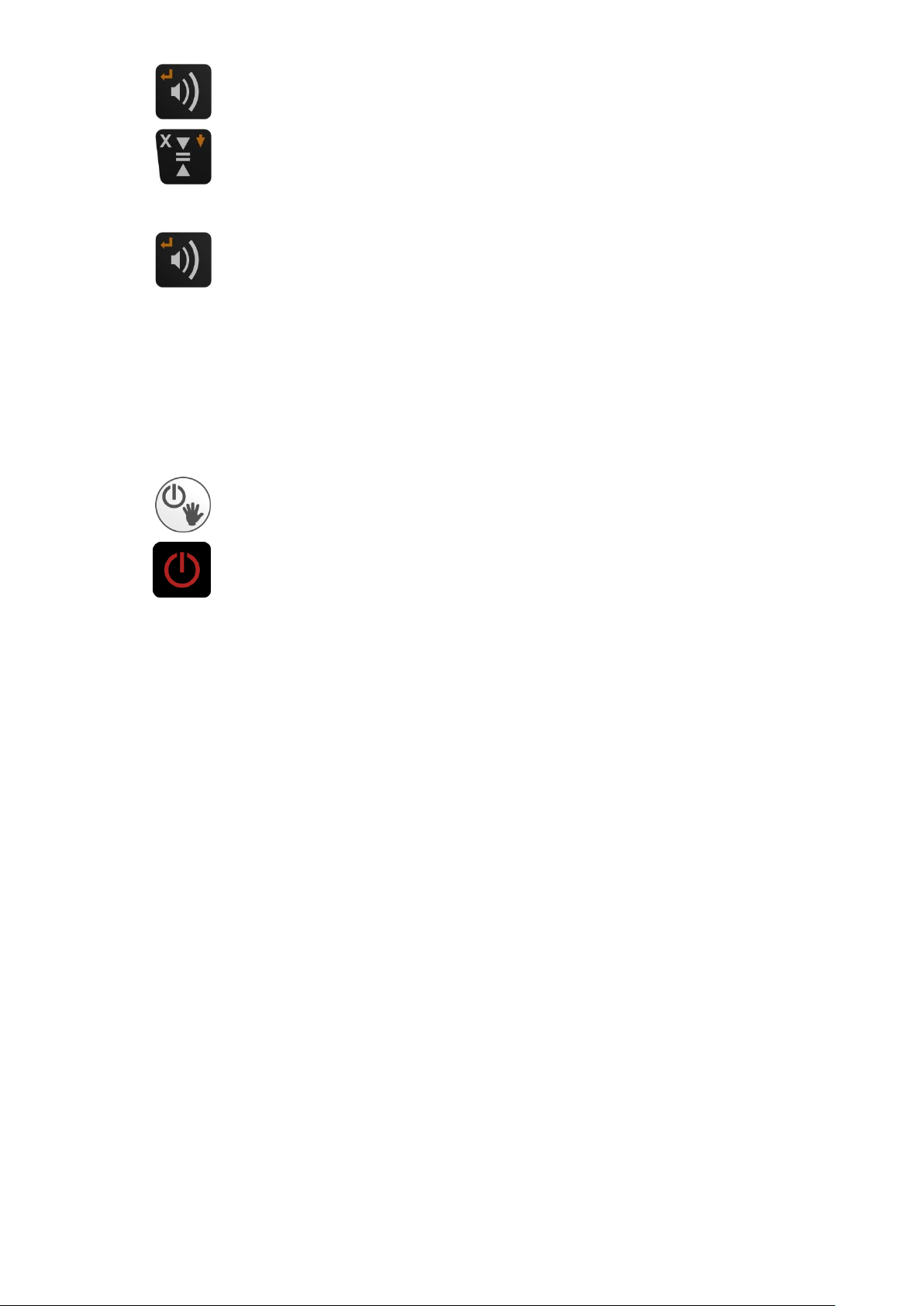
Menüpunkt auswählen
Drücken bis Menüpunkt…
PAr
…erscheint
Auswählen
Ok
Paarung erfolgreich
Paarung abschließen
9500
XXXX
Seriennummer TE 90 ALIGN auf Laser-Display
Laser ausschalten
3x drücken: Empfänger ausschalten
Nun sind Laser und Empfänger auf die gewählte Frequenz gepaart.
28
Page 29

16. Überprüfung der Justierung
Laser einschalten
5 Sekunden lang drücken
InFo
INFO- Anzeige
z. B. 1.5 CPU (Programm Version)
Sn (Seriennummer, 6-stellig)
h (Betriebsstunden)
Nächster Menüpunkt
Fb CH9 EU
Automatische Kanalwahl oder manuell einstellen.
Kanal wählen 1 – 16. (AUTO: Voreinstellung für automatische Wahl) Funk aus: Off
Frequenzwahl aktivieren (5 Sek. drücken)
Speichern und nächster Menüpunkt
% / ‰ – Einstellung
Laser-Nivellier, wie unter Kapitel 1 beschrieben (aber auf einem
sehr gut ausgerichteten Stativ) aufbauen und entlang einer etwa
30 m langen Messstrecke – beispielsweise mit der X-Achse beginnend – ausrichten und einschalten.
Am Ende der Messtrecke in Höhe des Laserstrahls eine Markierung vornehmen. Anschließend Laser – Gerät um 180° drehen und
erneut eine Markierung setzen. Danach die gleichen Maßnahmen
auch in der Y – Achse vornehmen. Falls alle Markierungen übereinander liegen oder nur unwesentlich (max. 3 mm) voneinander
abweichen, ist die Justierung in Ordnung. Falls größere Abweichungen vorliegen, muss das Gerät von einem Fachbetrieb überprüft und neu kalibriert werden.
17. Menü
Info und Einstellungen
29
Page 30
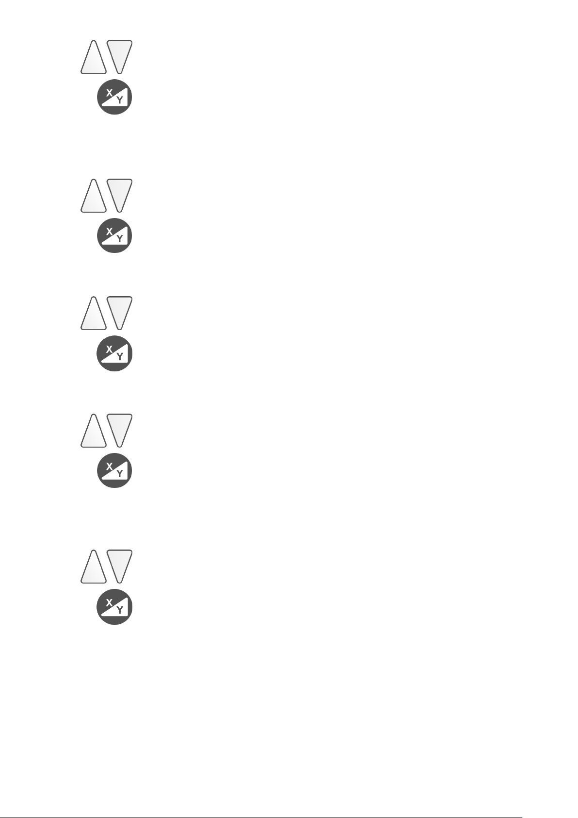
Einstellung (% - Einstellung ist Standard)
Speichern und nächster Menüpunkt
dEF
rPM
600
Startdrehzahl wählen
600, 800 oder 1000 U/min einstellen
Speichern und nächster Menüpunkt
Lcdb
SEC. 20
Display Beleuchtungsdauer
Wählen 0 – 250 Sekunden
Speichern und nächster Menüpunkt
Lcdb
Lich120
Beleuchtungsintensität
Wählen 0 - 250
Speichern und nächster Menüpunkt
SLP
hour
1
Standby-/ Sleep-Funktion Zeit einstellen.
Bei Wert „0“ deaktiviert
Wählen 0…10 Stunden
Speichern
30
Page 31
Info und Einstellungen FB – V
Zusammen drücken
z.B. 144522
Seriennummer
Nächster Menüpunkt
z.B. build 089
Software Version
Nächster Menüpunkt
z.B.
CH5 EU
Automatische Kanalwahl oder manuell einstellen
Kanal wählen 1 - 16 mit bestätigen.
Kanal CH Auto: Voreinstellung für automatische
Wahl)
EU
US wählen (Achtung: Nur für USA und AUS)
Speichern und nächster Menüpunkt
z.B. UbAt2.52
Volt (Batteriespannung FB - V)
Nächster Menüpunkt
APO
z.B. 60 SEC
Automat. Ausschalten der FB – V
5 – 600 Sekunden (Serieneinstellung 60 Sek.)
Speichern und nächster Menüpunkt
z.B. Lich140
Display Beleuchtungsintensität
Wählen 0 – 250
Speichern und nächster Menüpunkt
Lich
z.B. 20 SEC
Display Beleuchtungsdauer
Wählen 0 – 600 Sekunden
Speichern
31
Page 32

18. Lieferumfang
Standard Option
VISION 2N ALIGN Zielfernrohr
Akku ( 4 Monozellen) Funkfernbedienung FB - V
Netzgerät Stativ
Gebrauchsanleitung
Schutzkasten
TE 90 ALIGN
19. Betriebsanzeigen und Störungen
Displayanzeige:
Gerät zur Überprüfung an autorisierte Werkstatt oder direkt zum
Hersteller schicken.
20. Garantie
Wir gewährleisten für unsere Erzeugnisse eine dem heutigen Stand
der Technik entsprechende Fehlerfreiheit in Material und Werkarbeit. Sollten sich derartige Mängel beim praktischen Gebrauch zeigen, so werden diese kostenlos behoben. Die Garantiezeit beträgt
36 Monate (Ausnahme Akku 1 Jahr) ab dem Verkaufsdatum
(Rechnungsdatum). Für die Reparatur oder Umtausch sind Gerät
und/oder betroffene Teile unverzüglich nach Feststell ung des Mangels an THEIS zu senden.
Keine Garantieansprüche bestehen auf kostenlose Behebung von
Fehlern, die durch unsachgemäße Behandlung oder Aufbewahrung
entstanden sind sowie jegliche Schadensersatzansprüche, insbesondere auch solche auf mittelbare Schäden. Ferner erlischt jeder
Garantieanspruch, wenn technische Eingriffe von fremder Seite –
also nicht durch die Firma THEIS – vorgenommen werden.
32
Page 33
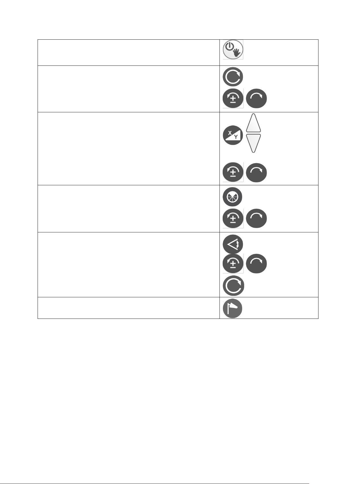
21. Kurzanleitung ohne ALIGN
Ein-/Ausschalten
Manueller Modus (5 Sek. drücken)
Drehzahl (U/min)
4 Stufen: 0 - 800
Verfahren des Laserstrahls (Schrittbetrieb)
Neigung
Anzeige letzte Eingabe
Eingabe X
Eingabe Y
Bestätigung
Ziffern - und Vorzeichenwahl
Ausblendmodus
Aktivierung 90 bis 270°: Deaktivierung
Positionieren des Ausblendbereichs
Scanmodus
5 Stufen, 10 bis 80°
Positionieren der Laserlinie
Scanmodus verlassen
Windy
Einstellung der Nivellierempfindlichkeit
33
Page 34

22. Technische Daten
Laser
Laserklasse / High Power
2 / 3R
Wellenlänge
635 - 660nm
Ausgangsleistung / High Power
< 1mW / < 5mW
Reichweiten
Siehe Empfänger
Selbstnivellierbereich
± 5°
Nivelliergenauigkeit
3,4
± 1,5 mm / 30 m
Neigungsgenauigkeit
3,4,5
± 0,1% bis 5% Neigung
Neigung X,Y / Align - Horizontal X,Y
± 10% / ± 15%
Align - Vertikal (Suchbereich)
≈ 9°
Drehzahl
0 – 800 U/min, 4-stufig,
Links-Rechtslauf im Schrittbetrieb
Scanmodus
5-stufig, Links-Rechtslauf im
Schrittbetrieb
Ausblendmodus
90 - 270° und positionierbar
Stromversorgung
NiMH
+
4x 1,2 V, 8Ah
oder 4x 1,5V Alkaline Mono-Zelle
Betriebsdauer Akku / Batterie
2,3
≈ 70h / 120h
Ladezeit
≈ 6h
Arbeitstemperatur
-15 bis + 50°C
Schutzart
IP 67 wasserdicht
Gewicht
≈ 3 kg
Funkfernbedienung
Reichweite
1,2,3
≈ 200 m
Empfänger TE 90 ALIGN
Empfangsfeld
90 mm
Numerische Anzeige
80 mm
Laser - Reichweite mit Grundgerät
1,3
350 m
Laser - Reichweite mit High Power
1,3
750 m
Reichweite ALIGN - Funktion
1,3,6
> 80 m bis zu 200 m
Anzeigegenauigkeit
siehe Tabelle 1
Anzeige
2 x LCD / 3 x LED
mm - Anzeige
ja
Stromversorgung
1 x AA
Betriebsdauer
2,3
> 45 h
Betriebstemperatur
-10°C … +50°C
Schutzart
IP 67
Größe
135 x 69 x 25 mm
Gewicht
≈ 190 g
1) Bei optimalen atmosphärischen Bedingungen 2) Bei optimalen Bedingungen
3) Bei 20°C 4) Parallel zu den Hauptachsen X, Y, Z
5) ohne Querneigung 6) Abhängig von der Orientierung des Lasers
34
Page 35

23. Lieferantenerklärung / Sicherheitshinweise
Das Gerät erfüllt die Forderungen folgender Richtlinien:
2004/108/EG, RTTE 1999/5/EG sowie 2011/65/EU
Zur Beurteilung des Erzeugnisses wurden folgende Normen
herangezogen:
EN 60950-1, EN 61000-6-3, EN301489-1, EN300220-1 V2.4.1,
EN 61000-6-2, EN301489-3 und EN300220-2 V2.4.1
Sicherheits-Hinweisschild befindet sich auf der linken Seite
des Gerätes
Eingebaut ist ein gekapselter Laser Klasse 3R (3B bei High
Power Version). Beim Öffnen des Gerätes besteht deshalb die
Möglichkeit, in den Bereich höherer Leistungswerte als der
Klasse 2 (3B bei High Power Version) zu gelangen. Laser nach
Möglichkeit nicht auf Personen ausrichten. Nicht in den Laserstrahl blicken, auch nicht mit optischen Instrumenten.
Es befinden sich keine zu wartenden oder justierenden Teile
im Inneren des Gerätes.
Service darf nur von autorisierten Stellen ausgeführt werden.
Sicherheitsvorschriften für
THEIS HIGH-POWER LASERGERÄTE Klasse 3R
Der Anwender muss die BGVB2 (Unfallverhütungsvorschrift für Laserstrahlung in Deutschland) beachten.
Dieses Produkt darf nur von geschultem Personal bedient
werden, um die Bestrahlung durch gefährliches Laserlicht zu
vermeiden.
Der Laser unterliegt der Klasse 3R
Warnschilder am Gerät nicht entfernen!
Strahlengang in größerer Entfernung beachten und sichern!
35
Page 36

Niemals in den Laser-Strahl blicken oder anderen Personen in
die Augen leuchten! Dies gilt auch in größeren Abständen vom
Gerät!
Laser immer so aufstellen, dass Personen nicht in Augenhöhe
angestrahlt werden (Achtung bei Reflexionen).
24. Entsorgung
Vermessungsgerät, Zubehör und Verpackung sollten einer umweltgerechten Wiederverwertung zugeführt werden.
Nur für EU-Länder:
Elektrowerkzeuge nicht in den Hausmüll werfen!
Gemäß der Europäischen Richtlinie 2012/19/EU über
Elektro- und Elektronik-Altgeräte und ihrer Umsetzung in
nationales Recht müssen nicht mehr gebrauchsfähige
Messwerkzeuge getrennt gesammelt und einer umweltgerechten Wiederverwertung zugeführt werden.
(WEEE - Reg.-Nr. DE 10598800)
Gemäß der Richtlinie 2006/66/EU müssen nicht mehr gebrauchsfähige THEIS Lasergeräte oder verbrauchte Akkus/Batterien recycelt
werden oder können direkt abgegeben werden bei Theis Feinwerktechnik.
Akkus/Batterien:
Batterien und Akkus sind Sondermüll und dürfen nicht in den
Hausmüll, ins Feuer oder Wasser gelangen.
THEIS FEINWERKTECHNIK GMBH
Zum Bolzenbach 26
D- 35236 Breidenbach
+ 49 (0) 6465 - 67- 0
+ 49 (0) 6465 - 6725
[email protected]
36
Page 37

37
Page 38

Contents
Introduction .....................................................................................41
Keyboard /Display ...........................................................................42
1. Horizontal Operation ...............................................................43
2. Vertical Operation/Alignment Mode ........................................43
3. Rotation - Speed .....................................................................44
4. Slope .......................................................................................44
5. Slope in Vertical Operation .....................................................45
6. Slope in Manual Mode ............................................................46
7. Mask Mode .............................................................................47
8. Scanning Mode .......................................................................47
9. Setting the Levelling Sensitivity (Windy) .................................48
10. TILT Function ..........................................................................48
11. Power Supply of Laser ............................................................49
12. Radio Remote Control FB-V (Option) .....................................50
13. Detector TE 90 ALIGN ............................................................52
13.1 Keyboard ..........................................................................52
13.2 Operation ..........................................................................53
13.3 Power supply of detector ..................................................55
14. ALIGN – Function ...................................................................56
14.1 ALIGN – Horizontal ..........................................................56
14.1.1 Setup/process ...........................................................56
14.1.2 Operation / display ....................................................57
14.1.2.1 Slope Y axis (Figure 1) .....................................57
14.1.2.2 Slope Y- and X - axis (Figure 1) ........................58
14.2 ALIGN - Vertical (Alignment) ............................................60
14.2.1 Setup/process ...........................................................60
14.2.2 Operation / display ....................................................61
14.3 Error displays....................................................................62
15. Pairing of laser und detector ...................................................63
16. Calibration Check ...................................................................65
38
Page 39

17. Menu ....................................................................................... 65
18. Delivery Contents ................................................................... 68
19. Special Indications and Troubleshooting ................................ 68
20. Warranty ................................................................................. 68
21. Brief Instructions ..................................................................... 69
22. Technical Data ........................................................................ 70
23. Supplier Declaration/Safety Information ................................. 71
24. Disposal .................................................................................. 72
39
Page 40

40
Page 41

Instruction manual
EN
Introduction
VISION 2N ALIGN
... for the construction professional.
The rotation laser THEIS VISION 2N ALIGN sets new standards in
the area of fully automated professional lasers.
It is the result of many years of experience and innovative technology.
The high-quality construction laser is distinguished by its ruggedness and high precision – Made in Germany – and no construction
site should do without it.
To ensure that your device is always ready for use, observe the
following information:
1. Never store the device in the container when it is wet.
2. Check the precision every time before you use the equipment,
since we can accept no liability for misalignment.
3. Observe the information on handling the battery.
4. Treat carefully the laser exit and sensor windows of the optional
detector.
41
Page 42
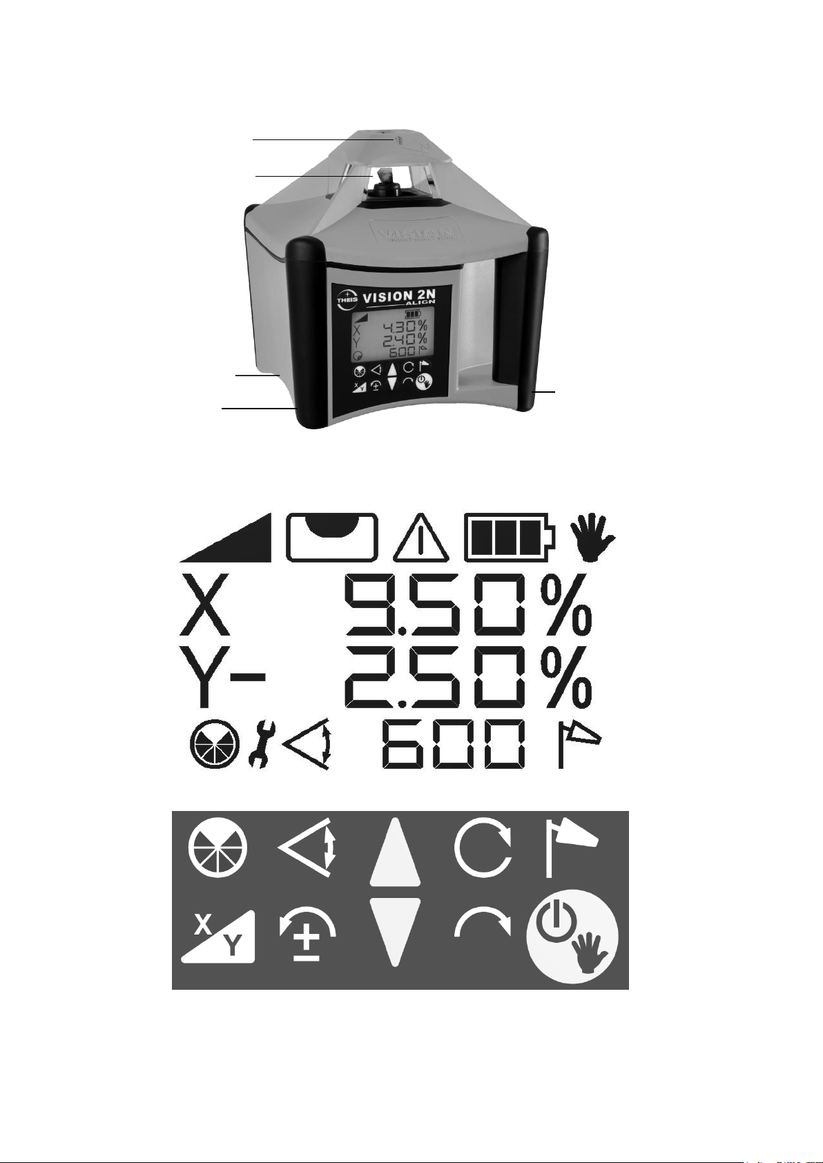
Keyboard /Display
X/Y axis
slope
Slope
Manual
mode
Levelling
display
End stop,
Position change
Battery
display
Mask Disturbance
mode
Scan
Windy
Speed or
Scan-stop
Slope
X/Y axis
Counter clockwise
rotation step mode,
Selection of numbers and signs
Slope
Clockwise
rotation step mode,
Selection of
numbers and signs
On/Off,
Manual
mode
Laser exit rotation
Charging socket
Battery compartment
Optical sight
Productinformation
Via QR-Code on reverse, e.g. Instruction
manual
A
42
Page 43
1. Horizontal Operation
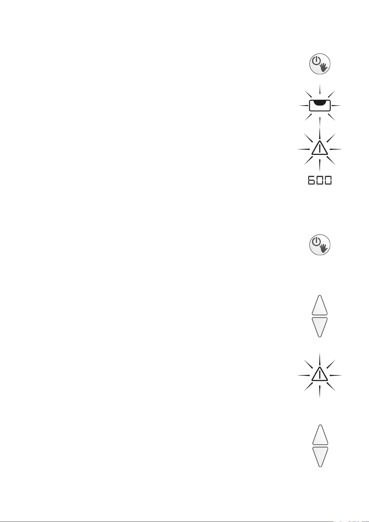
Align the tripod and screw the TPL tight using the tripod
screw. The precision of alignment affects the size of the
slope range. Use the On/Off switch to switch on the
device.
The levelling indicator flashes on the lit display.
If the tripod head is sloping by more than 5°, this is
indicated by the laser beam flashing quickly and the
alarm symbol being displayed.
In this case, switch off the unit and align the tripod more
carefully.
Once horizontal levelling is completed, the laser beam
starts to rotate.
2. Vertical Operation/Alignment Mode
Set up the laser or fasten it to the tripod such that the
keypad is facing upwards. If necessary, use the 5/8“nut
to screw it on the tripod. Use the On/Off button to switch
on the laser. For more information, refer to point 1.
Use the arrow keys to align the laser beam. Pressing
the arrow key and holding it down speeds up alignment
of the laser beam.
If the traverse path is exceeded while aligning, this is
indicated by a change in the arrangement of the bars,
by a quickly flashing warning symbol and by the laser
beam.
You can clear the end stops again using the arrow keys.
_ _ _
_ - _
-
_ -
43
Page 44
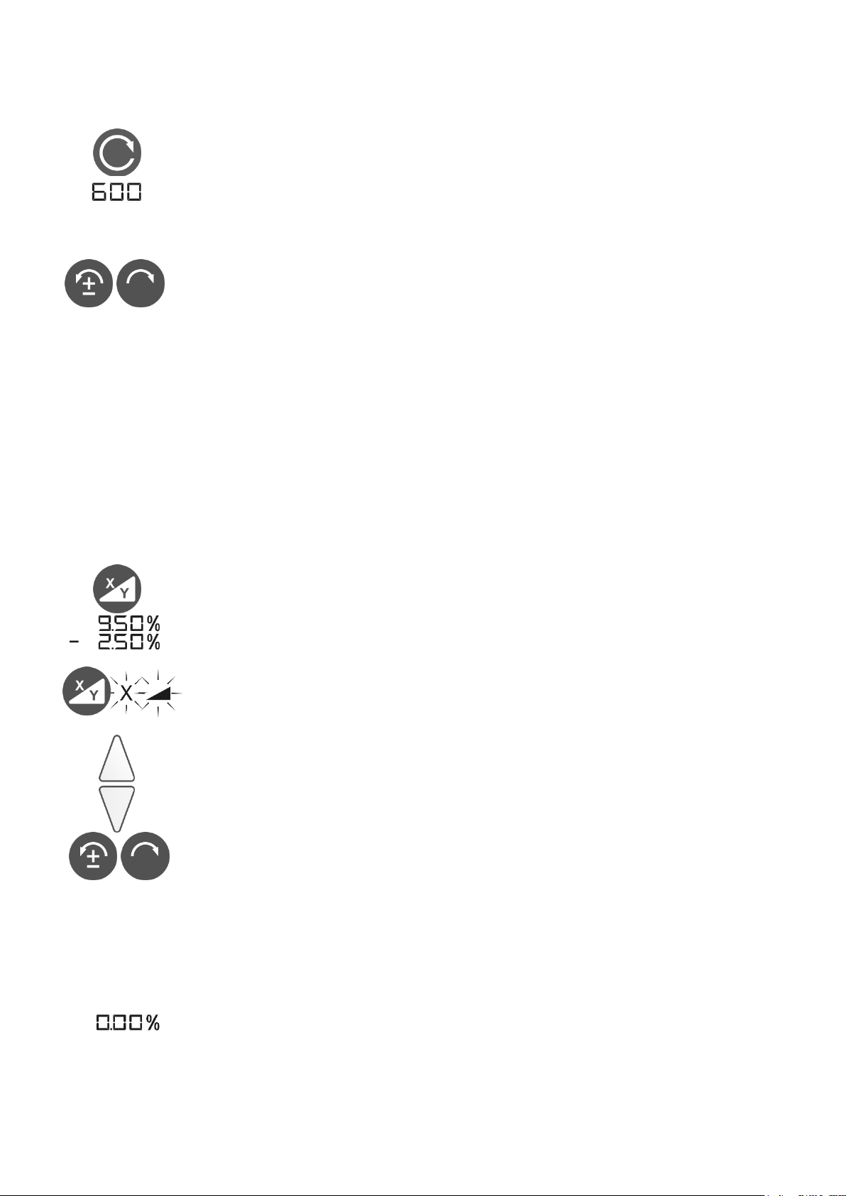
3. Rotation - Speed
The rotation speed can be regulated in four stages: 0,
200, 600 and 800 RPM. Pressing the rotation key two
times the laser stops 0 RPM). Each time you press the
key again, the rotation speed increases.
At a standstill, you can move the laser dot using the
counterclockwise/clockwise rotation keys. Pressing
and holding down one of the keys speeds up the
movement of the laser dot.
4. Slope
If the tripod is well-aligned, you can grade the laser on
two axes from -10% to +10%.
To do this, first use the optical sight to align the laser
exactly to the target point and then enter the slope
settings as follows:
1st key press: Grading is activated. The stored slope
settings of the last use are displayed and automatically
approached.
2nd key press: X, slope symbol and one digit of the
slope value flashes on the display.
Use the arrow keys to set the slope. The blinking digit
can be changed.
To select the digits you must press the counterclockwise/clockwise rotation keys. For changing the sign
use the ± button. Plus is not displayed.
When you press and hold the arrow - keys the values
in the display will start to increase slowly and speed up
than.
Pressing both arrow keys at the same time resets the
respective display to 0.
44
Page 45
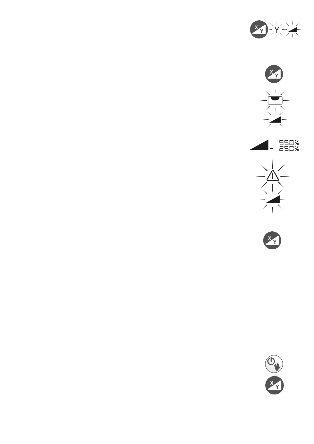
3rd key press: Y flashes on the display.
You can now use the arrow keys to set the slope of the
Y axis in the same way as for the X axis.
4th key press: Confirms your input
After this, the device first starts levelling again, which is
shown by the flashing levelling display. After this, the
entered slope settings are approached.
During this procedure, the slope symbol blinks.
Once the values have been reached, the slope settings
and the slope symbol are displayed permanently lit.
If external influences (shock or temperature) change the
position of the device, the system interrupts rotation and
the laser beam, the slope and the warning display flash
rapidly.
If you press the slope key again, you can start grading
again, the device carries out levelling again and
approaches the stored slope settings again.
Important: The laser's mounting position and
possibly also the elevation and direction may,
however, have changed. This means that to be on
the safe side you should switch the device off and
back on again and adjust it.
5. Slope in Vertical Operation
In vertical operation too you can enter a grade. Of
course, you can only do this on the Y axis. To do this,
fix the laser in vertical position, start the laser and press
the X/Y key. Proceed as described in point 4.
45
Page 46
X
Y
6. Slope in Manual Mode
To be able to set higher grades using a level table or to
record building-side specified grades, for example, you
must switch off the device's automatic system.
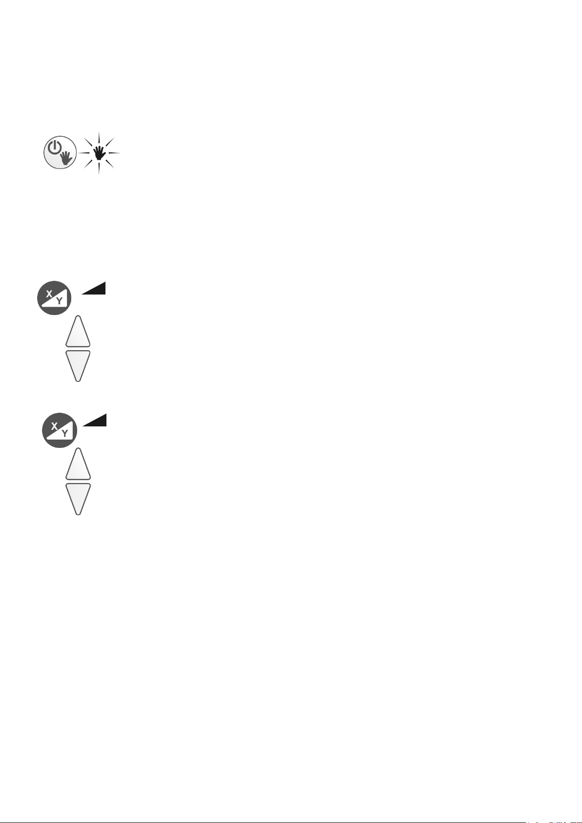
You do this by pressing the On/Off key for a long time
(approx. 5 sec.) Manual mode is shown on the display.
Now align the laser exactly to the target point using a
sighting telescope or the optical sight and enter the
grade:
1st key press: Slope symbol and X is shown on the
display.
Use the arrow keys to approach the slope.
2nd key press: X - Symbol disappears but slope symbol
and Y is shown in the display.
Use the arrow keys to approach the slope.
You can set both PLUS and MINUS grades. While you
press the bottom arrow key, MINUS is shown on the
display. With the top (Plus) arrow key, there is no indication on the display.
Important: In manual mode, there is no automatic
laser self-levelling!
46
Page 47
7. Mask Mode
In mask mode, you can limit the laser exit to a settable
range.
This is only possible with a rotating laser beam, i.e. not
in scanning mode.
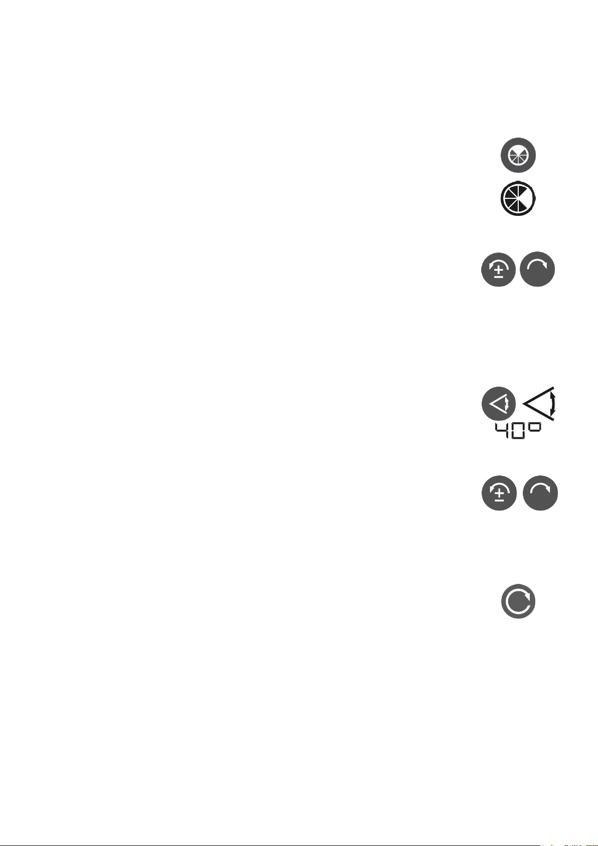
By pressing the key three times you enlarge the masked
area from 90 up to 270°. With the 4th press you leave
the mask mode. The switched-off area is displayed
black. In the light area, the laser beam is still emitted.
Using the counterclockwise/clockwise rotation keys, you
can rotate the mask area in the desired direction.
8. Scanning Mode
You get to scanning mode by pressing the Scan key. It
is possible to generate five different sizes of laser line.
The scanning angle increases each time you press the
Scan key again. The respective size of the laser line is
shown on the display (10°, 20°, 40°, 60°, 80°)
Using the counterclockwise/clockwise rotation keys, you
can travers the laser line appropriately. Pressing and
holding down one of the keys speeds up the movement
of the laser line.
When leaving scanning mode by pressing the rotation
key, the system stores the last position of the rotor
head. This means that if you select scanning mode
again at a later date, the system traverses to the
position of the laser line you selected last.
47
Page 48

9. Setting the Levelling Sensitivity
(Windy)
If while working with the device you have to relevel it
due to wind, vibrations or slight shocks, which interrupt
the rotation, you can remedy this situation using the
Windy function.
Pressing the Windy key reduces the leveling sensitivity
of the instrument.
The Windy key is blocked in grade mode.
10. TILT Function
In the case of major changes to the mounting position
(e.g. accidentally moving the tripod leg), a TILT function
ensures that the device switches off and draws attention
to the fact by the laser beam and the warning triangle
flashing quickly.
After this, you must restart the device.
48
Page 49
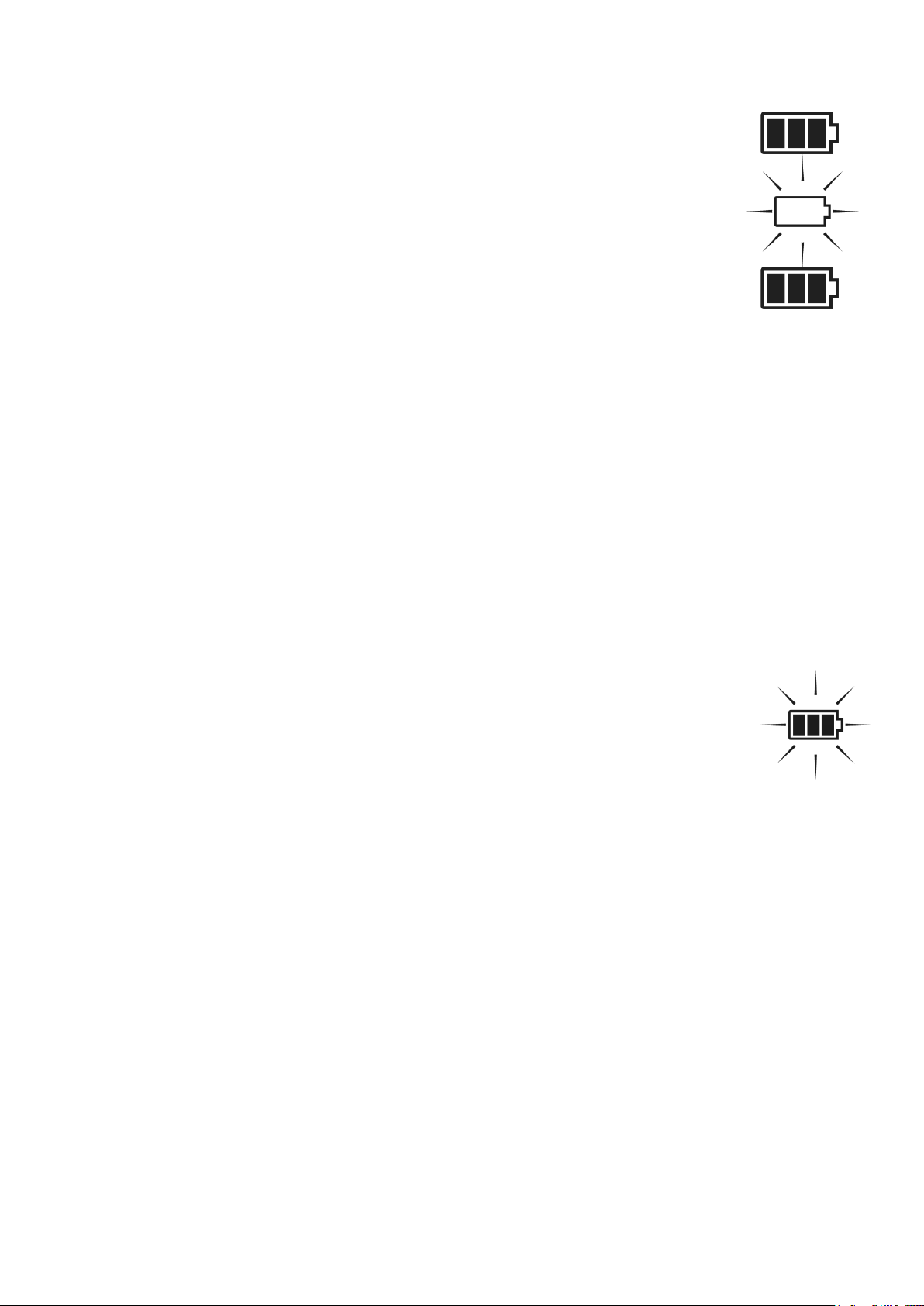
11. Power Supply of Laser
The battery level indicator shows the battery status in
four steps.
If the three bars on the display are blank and the outside
frame flashes, the battery is flat and you must charge it.
If you do not notice this, the device switches off automatically after a certain amount of time.
During charging the three bars flash from top to bottom.
When the battery is fully charged, all the bars are shown.
Charge the battery at room temperature using only the
THEIS standard mains unit connected to the charger
socket below the laser. Charging at temperatures below
+5°C can lead to defects in the battery.
Charging is also possible during operation. Overloading is
not possible.
Only use the charger on dry premises!
The batteries that are used with Eneloop™ technol-
ogy have the advantage of low levels of selfdischarge. This means that if you do not use the device, you only need to recharge it every six months
In the battery compartment, you can also use normal
alkaline mono-cells. Under no circumstances must you
recharge them. If you do this by mistake, the battery
symbol flashes.
Important: Observe the correct polarity. There are ±
symbols on the base of the battery compartment.
Observe the disposal information in point 24.
Important: Because the battery poles and contacts may soil
over time, resulting in contact problems, regular inspection
and possibly cleaning with a soft cloth and cleaning agent
(spirit, alcohol) are necessary.
49
Page 50
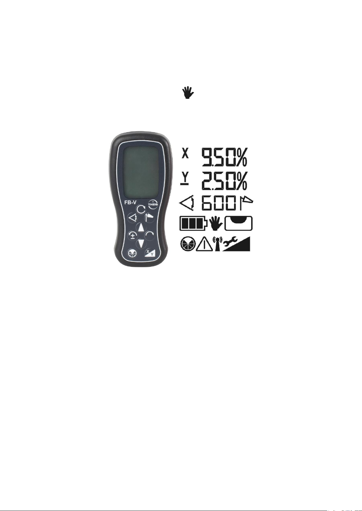
12. Radio Remote Control FB-V (Option)
The wireless remote control is designed on a bidirectional
basis. All the information that is shown on the laser's display
can also be seen on the lit-up display of the remote control. The
key symbols on the operator panel correspond to the keys on
the laser keypad. The MANUAL operating mode is missing
to ensure that it is not possible to enter this function by mistake.
Die FB-3 durch Drücken einer beliebigen Taste einschalten. Die
Switch on the FB - V by pressing any key. The remote control
automatically searches for an appropriate channel to rule out
disturbances to other devices.
On the display, you can see the same information as on the
display of the associated laser. If this is not the case and an
antenna symbol is displayed, this may be due to one of the
following reasons:
- The laser is not switched on
- The radio channel is not set correctly
- The remote control is out of range of the laser.
Pressing both arrow keys switches off the laser. The FB - V
switches itself off after 1 minute.
If the Standby-/Sleep-function is activated to save the capacity of
the battery (see capital 17), the laser can be set in standby-mode
by pressing both arrow-buttons on the remote control. With any
50
Page 51

button on the remote control the standby-mode can be stopped.
The instrument will return to normal operation, as if the instrument
will be switched on. The maximum standby-period can be set at the
info-menu (see capital 17). The laser switches off if standby-period
is exceeded.
Power is supplied by two alkaline micro AAA batteries. The service
life is approximately 60 hours.
The battery symbol shows the status of the FB - V's batteries.
To change the batteries, open the cover on the back and replace
the batteries. Observe the correct polarity. For information on
disposal, see point 24.
51
Page 52
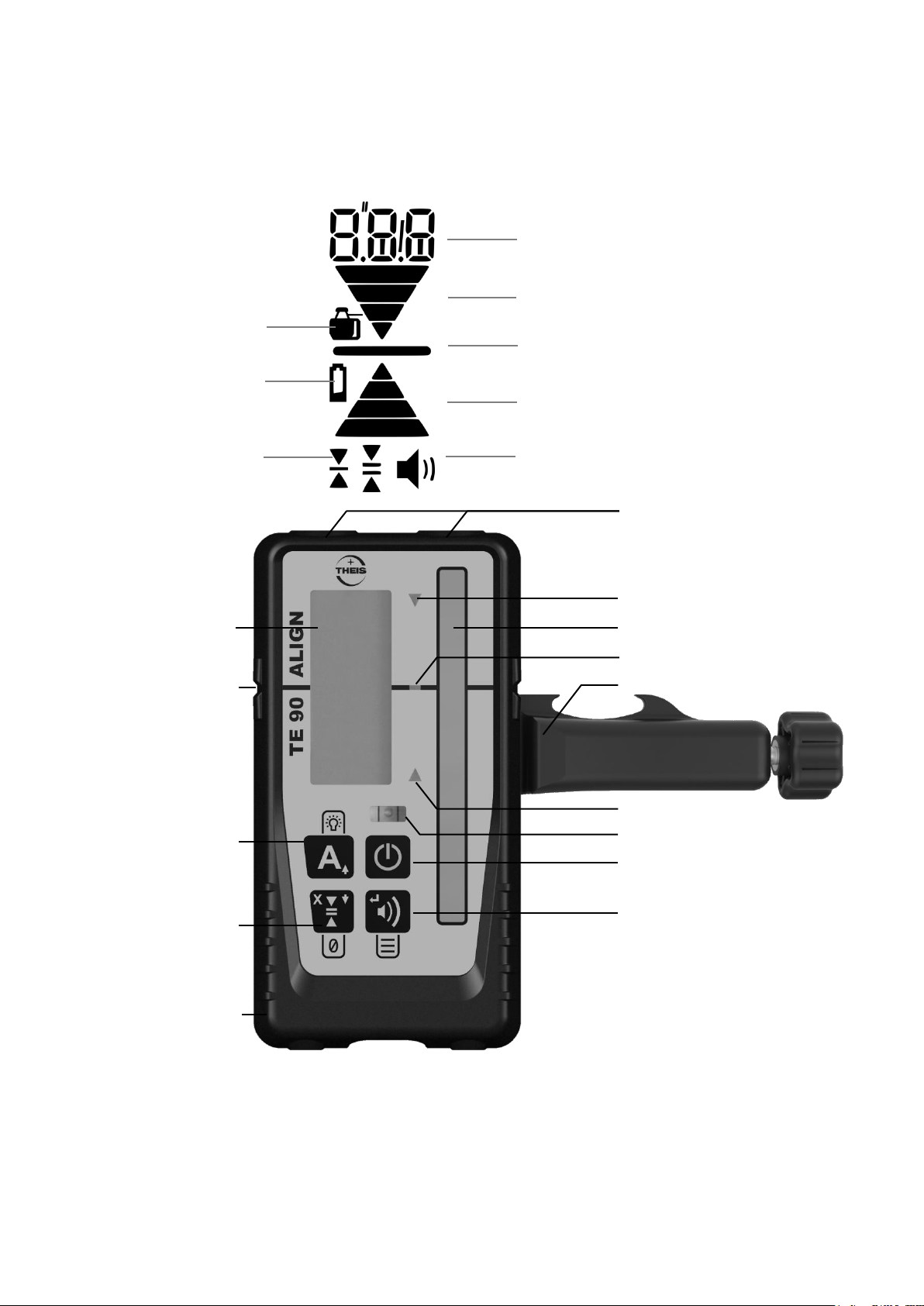
13. Detector TE 90 ALIGN
LED: Direction of movement
LED for Centre
Sensor window
LED: Direction of movement
Bubble vial
Button On / Off
Button audible signal /
Menu: ENTER button
Magnet
Display
(on reverse too)
Centre notch
Button:
Short: Align On/Off
Long: LEDs On/Off
Menu: Arrow button up
Button:
Short: Accuracy
Long: Set reference
Menu: Arrow button
down
Fixing clamp
Accuracy
Battery display
Display of audible signal
Arrow for direction of movement
Centre bar
Arrow for direction of movement
Numeric digits / text display
Battery compartment
(on reverse)
Device symbol:
Laser connected
13.1 Keyboard
52
Page 53

13.2 Operation
mm
cm
inch
Fract.In.
Display
Ultra fine
0.5
0.05
0.02
-
flashing
Fine
1.0
0.1
0.05
1/8
non- flashing
Medium
2.0
0.2
0.1
1/4
non- flashing
Coarse
5.0
0.5
0.2
1/2
non- flashing
Ultra coarse
10.0
1.0
0.5
-
flashing
Switching the device on / off
Press the On / Off button
Adjusting the volume
Pressing the audible signal button cycles Low / High / Off
High: Display of audible signal permanently displayed;
text "Hi" for one second
Low: Display of audible signal permanently displayed;
text "LOW" for one second
Off: No Display of audible signal displayed;
text "OFF" for one second
Adjusting the accuracy
Press accuracy button once to numerically display current accuracy
setting on the LCD. Press again, while the accuracy is displayed
(within one second), to change the current selection. Subsequent
presses will cycle through five accuracy options Ultra fine / Fine /
Medium / Coarse / Ultra coarse.
Table 1: Accuracy
Activate / deactivate LEDs
Press the LEDs On-Off button to change the LED display. If activated, the measurements are shown by the LEDs in addition to the
display.
53
Page 54

User defined on-grade level:
An arbitrary level within -10 and +40mm around the Centre notch
can be used as on-grade level. The user defined on-grade level is
set by pressing the accuracy button for two seconds while the device is in the laser beam. If successful, you will hear a confirmation
beep and an asymmetric arrow symbol is shown on the display.
Outside the allowed area you will hear an error beep and error code
E30 is shown. When the accuracy button is pressed for two seconds while out of beam, the on-grade level is reset to default. If the
device is switched off, the on-grade level is automatically reset to
default.
Using the menu
The menu functions can be used to edit various options. For most
applications the factory defaults are best choice. We recommend to
change settings only in special applications.
Pressing the audible signal / ENTER button for more than two
seconds enters the menu functions.
Menu items (e.g. SEn) are shown non-flashing and may be
browsed by using the arrow up / down buttons.
Menu items are selected by pressing the audible signal / EN-
TER button.
Item values (e.g. On) are shown flashing and may be browsed
by using the arrow up / down buttons.
Exit the Menu by pressing the On / Off button.
Menu Entries:
SEn - Sensitivity: Hi(gh) / Low
Default: High. Set it to Low if you have problems with disturbing
sources like fluorescent or strobe lights.
AvG - Averaging: Hi(gh) / Low
Default: Low. Set it to High if you need to have more stable readings under difficult atmospheric conditions.
Unt - Unit: mm / cm / in(ch) / f(ract). in(ch)
Default: mm. Choose desired numeric elevation display unit.
54
Page 55

o.o.b - Out of beam display: On/OFF
Default: OFF. Switch Out-of-beam display on and off. A sequence
of arrows indicates if the detectorhas moved beyond the vertical reception range and will indicate in which direction to move to get
back to the laser beam.
Inf - Device Information
Find Information about Firmware Version (Fw), Device Code (dc)
and Serial Number (Sn) here.
ALG – Detector alignment for ALIGN - function
Default: "Hor" "UP" / "Ver" "UP". Setting “UP” und “dwn” pos-
sible.
Setting “UP“ horizontal: Text „THEIS“ of Logo upright readable
Setting “UP“ vertical: Text „TE 90 ALIGN“ upright readable
NOTE: All menu settings will be retained when the detector is
turned off.
13.3 Power supply of detector
If the battery symbol is shown on the LCD display, you should change
the battery (1xAA); otherwise, the range may be limited.
Open the folding lid of the battery compartment to change the battery.
Dispose of used batteries correctly (see point 24 ) and ensure the correct polarity with the new batteries (observe the symbols).
55
Page 56
14. ALIGN – Function
14.1 ALIGN – Horizontal
14.1.1 Setup/process
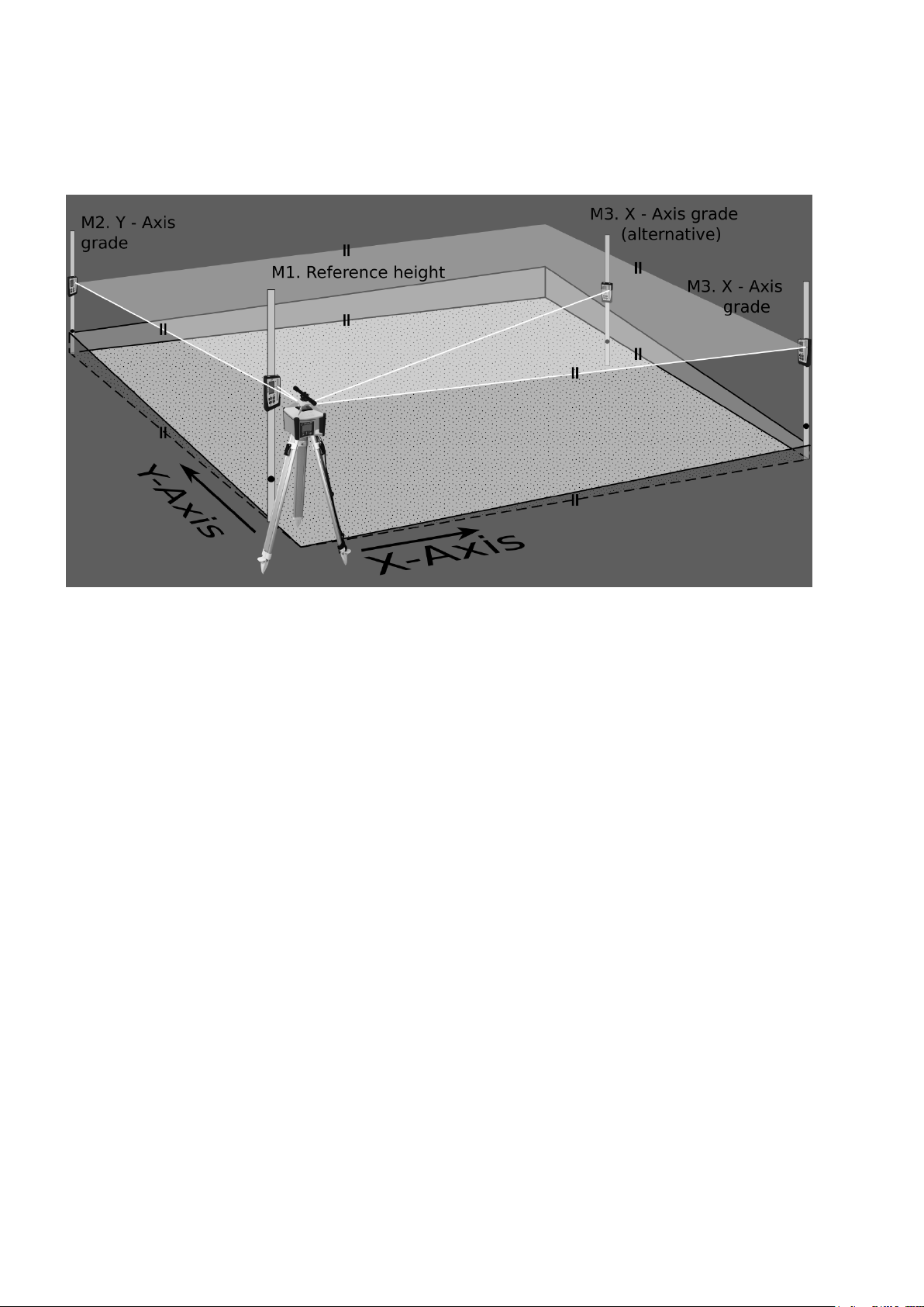
Figure 1: ALIGN setup – Horizontal
Two grades can be set automatically in the X and Y axis with the
laser system Vision 2N ALIGN and the detector TE 90 ALIGN.
First set up the static head horizontally, as described under Section
4 and set the laser in the Y direction flush with the first target point
M2 (Figure 1). Use the telescopic sight (option) if the determined
grade values are to be as accurate as possible.
Then set up the laser yardstick with the detector as short a distance
away from the laser as possible (Figure 1: M1 reference height) and
switch on both devices as described in Sections 1 and 13.2 and
place the detector centre level with the laser beam.
The purpose of this dimension is to serve as the reference
height for the entire measurement and may not be altered again.
Set up detector/laser yardstick at the target point M2 and record the
initial grade of the Y axis. (See Table 2)
Important: To obtain accurate grade values, the first inclination position point must lie exactly on the Y axis of the laser.
56
Page 57
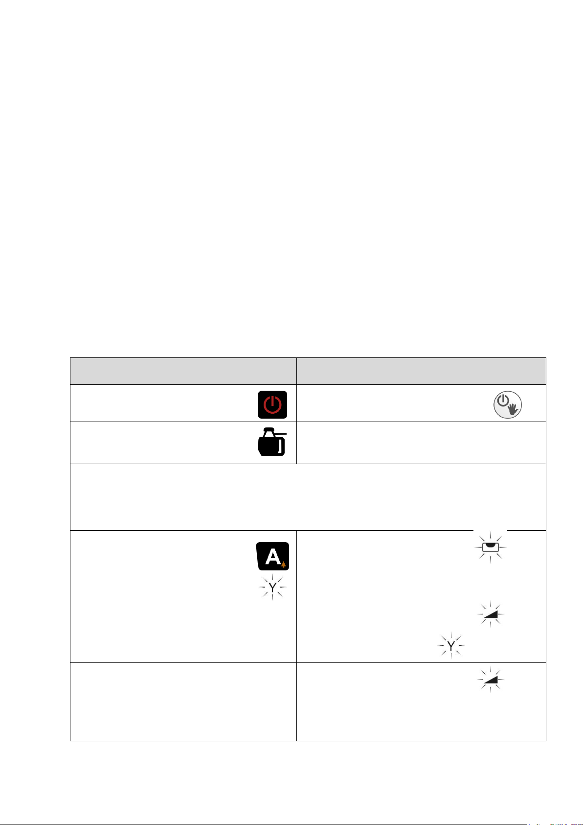
The telescope available from THEIS is definitely recommended
TE 90 ALIGN
VISION 2N ALIGN
Turn on the detector.
Turn on the laser.
Device symbol must always be displayed.
Set detector at short distance before laser to reference height.
Then move detector to target point M2. M2 must be exactly on the
Y axis (telescopic sight recommended).
Y axis
Press A key briefly.
Start ALIGN in Y axis.
Laser approaches
end switch and
levels.
Leveling begins.
Laser searches
for detector.
0.00% A
Search complete:
Y or Y alternating and slope
value _._ _ flashing in alternation.
Detector found.
Y
_._ _% A
for this.
Note:
(1) While searching for the detector, changes may occur in the ro-
tation speed and in the blanking zones.
(2) There must be no obstructions between laser and detector,
otherwise this will impact the search speed and make searching more difficult.
(3) If a second normal detector is to be used during the ALIGN
state, to determine intermediate points, for examp le, take care
that you do not cover the receiving field of TE 90 ALIGN with
this detector, but remains below or above it. This could result
in an incorrect result.
14.1.2 Operation / display
14.1.2.1 Slope Y axis (Figure 1)
57
Page 58
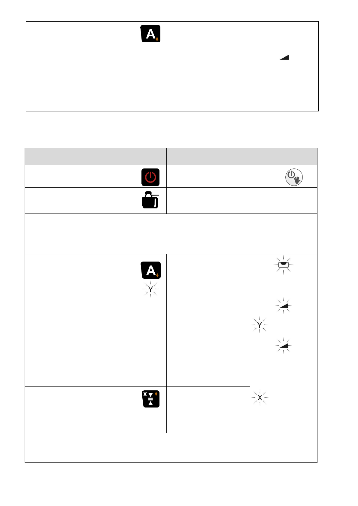
Table 2: ALIGN - Function horizontal Y-axis
End ALIGN:
Press A key briefly:
ALIGN deactivated.
Detector is now in
standard operation and
can be re-moved.
Detector - Tracking stops.
Grade value Y
stored.
Laser in standard
grade function.
Y
_._ _%
TE 90 ALIGN
VISION 2N ALIGN
Turn on the detector.
Turn on the laser.
Device symbol must always be displayed.
Set detector at short distance before laser to reference height.
Then move detector to target point M2. M2 must be exactly on the
Y axis (telescopic sight recommended).
Y axis
Press A key briefly.
Start ALIGN in Y axis.
Laser approaches end switch
and levels.
Leveling begins.
Laser searches
for detector.
0.00% A
Search complete:
Y or -Y alternating and slope
value _._ _ flashing in alternation.
Detector found.
Y
_._ _% A
X axis
Press Display accuracy
key/X.
H
Grade value Y is
stored.
0.00%
Y
_._ _% A
The grade in the Y axis will not be adjusted any further.
Move detector to target point M3 for X – slope.
14.1.2.2 Slope Y- and X - axis (Figure 1)
58
Page 59
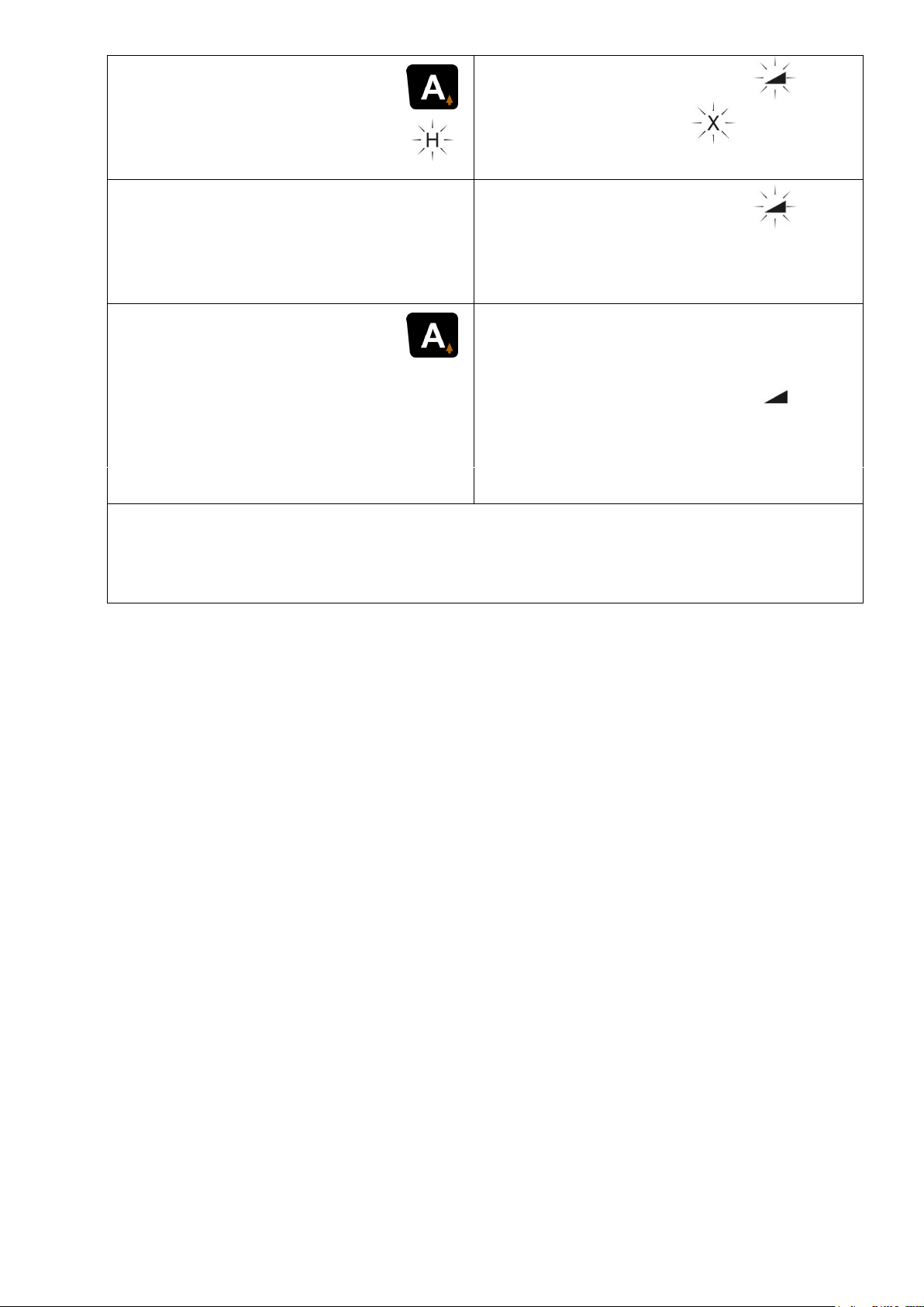
Table 3: ALIGN - Function horizontal Y – and X-axis
Press A key briefly:
Start ALIGN in X axis.
Laser searches
for detector.
0.00%
Y
_._ _% A
Search complete:
X or -X alternating and slope
value _._ _ flashing in alternation.
Detector found.
X
_._ _%
Y
_._ _% A
End ALIGN:
Press A key briefly:
ALIGN deactivated.
Detector is now in
standard operation and
can be re-moved.
Detector - Tracking stops.
Grade value X
stored.
Laser in standard
grade function.
X
_._ _%
Y
_._ _% A
The pitch is not adjusted any further in any axis, but is monitored to
identify any bigger possible change in the position of the laser. See
also Section 4 because of warnings.
Important: If the laser is brought out of position accidentally,
the entire measurement will have to be repeated.
59
Page 60
14.2 ALIGN - Vertical (Alignment)
14.2.1 Setup/process
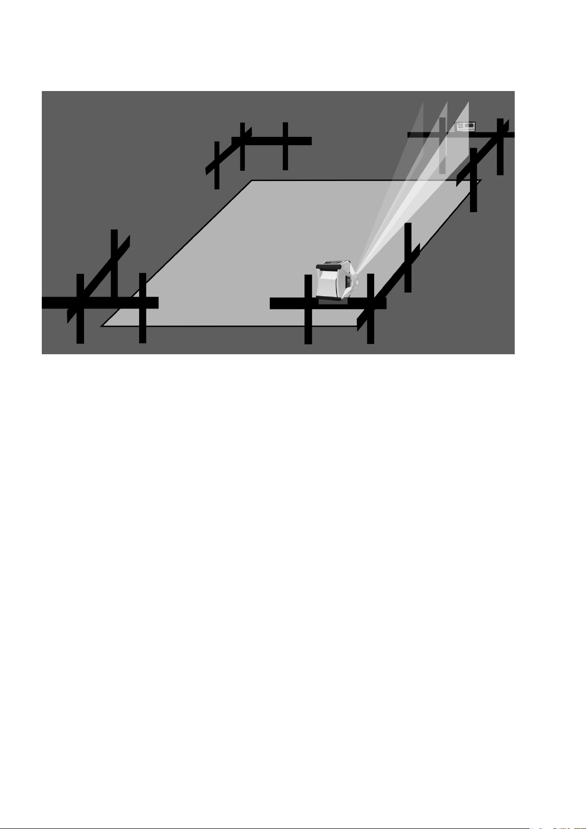
Figure 2: ALIGN - Vertical
The laser system Vision 2N ALIGN with the detector TE 90 ALIGN
can be used in vertical operation and for flush alignment.
To do this, place the laser on a stand, the ground or a batter board,
for example, as described in Section 2. The example of use batter
board is explained in the following.
Set up the laser based on Figure 2 so that the vertical laser level is
aligned flush above the nail.
Move detector TE 90 ALIGN to the required target point. Align the
detector in such a way that the logo "TE 90 ALIGN" can be read
when upright. (The orientation of the detector can also be changed
in the detector menu page 55).
Note:
(1) Set up the detector as far away as possible from the ground
(at least 10 cm, better 100 cm). The greater the distance the
greater the wireless range. The detector must be within the
search range of the laser (+/9°).
(2) While searching for the detector, changes may occur in the ro-
tation speed and in the blanking zones.
60
Page 61
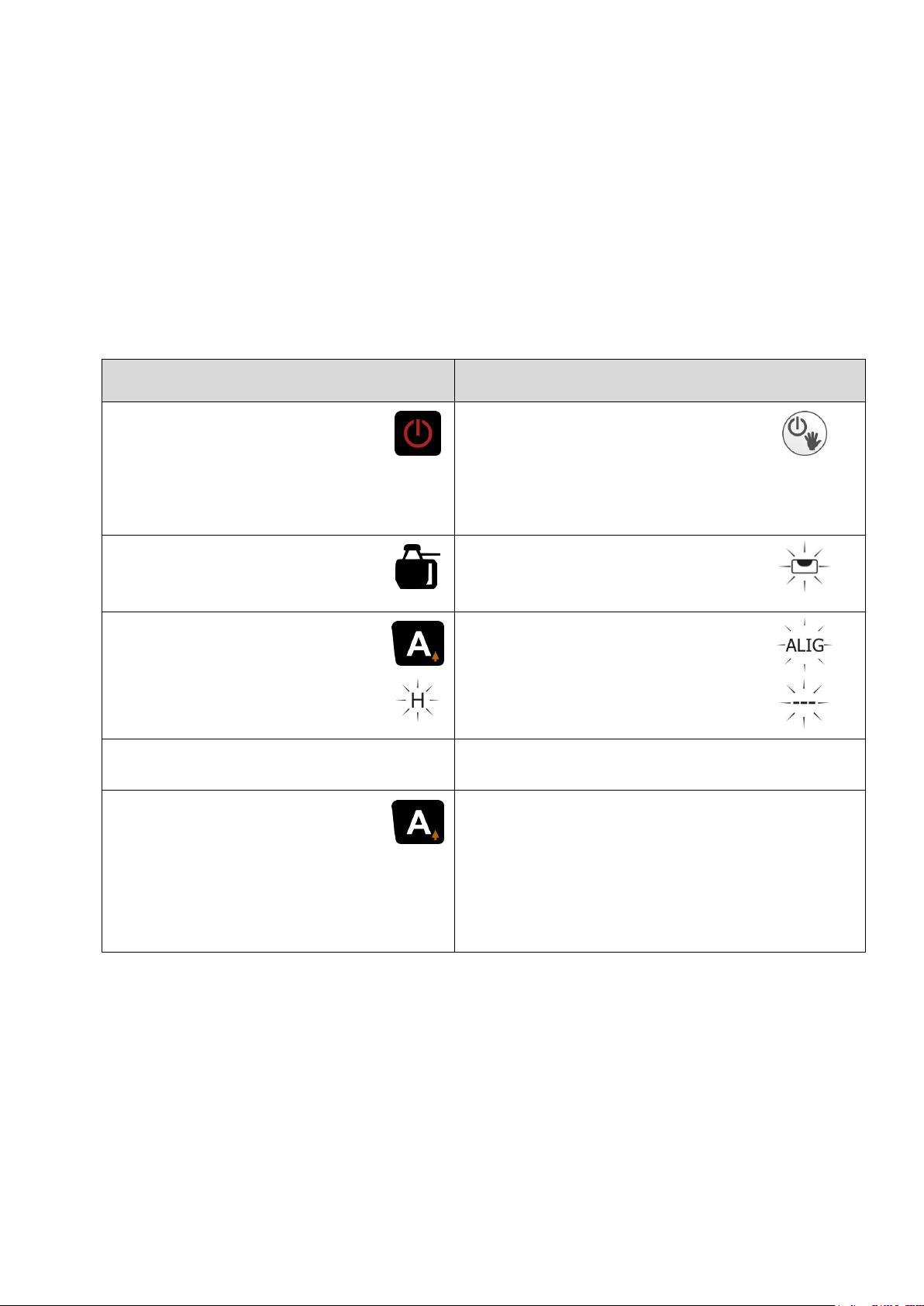
(3) There must be no obstructions between laser and detector,
TE 90 ALIGN
VISION 2N ALIGN
Turn on the detector.
Detector orientation:
Text „TE 90 ALIGN“ upright readable.
Turn on the laser.
Display up.
Device symbol must be
displayed.
Laser leveled.
Press A key briefly.
Start ALIGN in X axis.
Laser searches for
detector:
Display.
H
Detector found.
ALIG
– – –
Press A key briefly:
ALIGN deactivated.
Detector is now in
standard operation and
can be removed.
Detector - Tracking stops.
Laser in vertical standard opera-
tion.
otherwise this will impact the search speed and make searching more difficult.
(4) If a second normal detector is to be used during the ALIGN
state, to determine intermediate points, for example, take care
that you do not cover the receiving field of TE 90 ALIGN with
this detector, but remains below or above it. This could result
in an incorrect result.
14.2.2 Operation / display
Table 4: ALIGN - Function vertical
61
Page 62
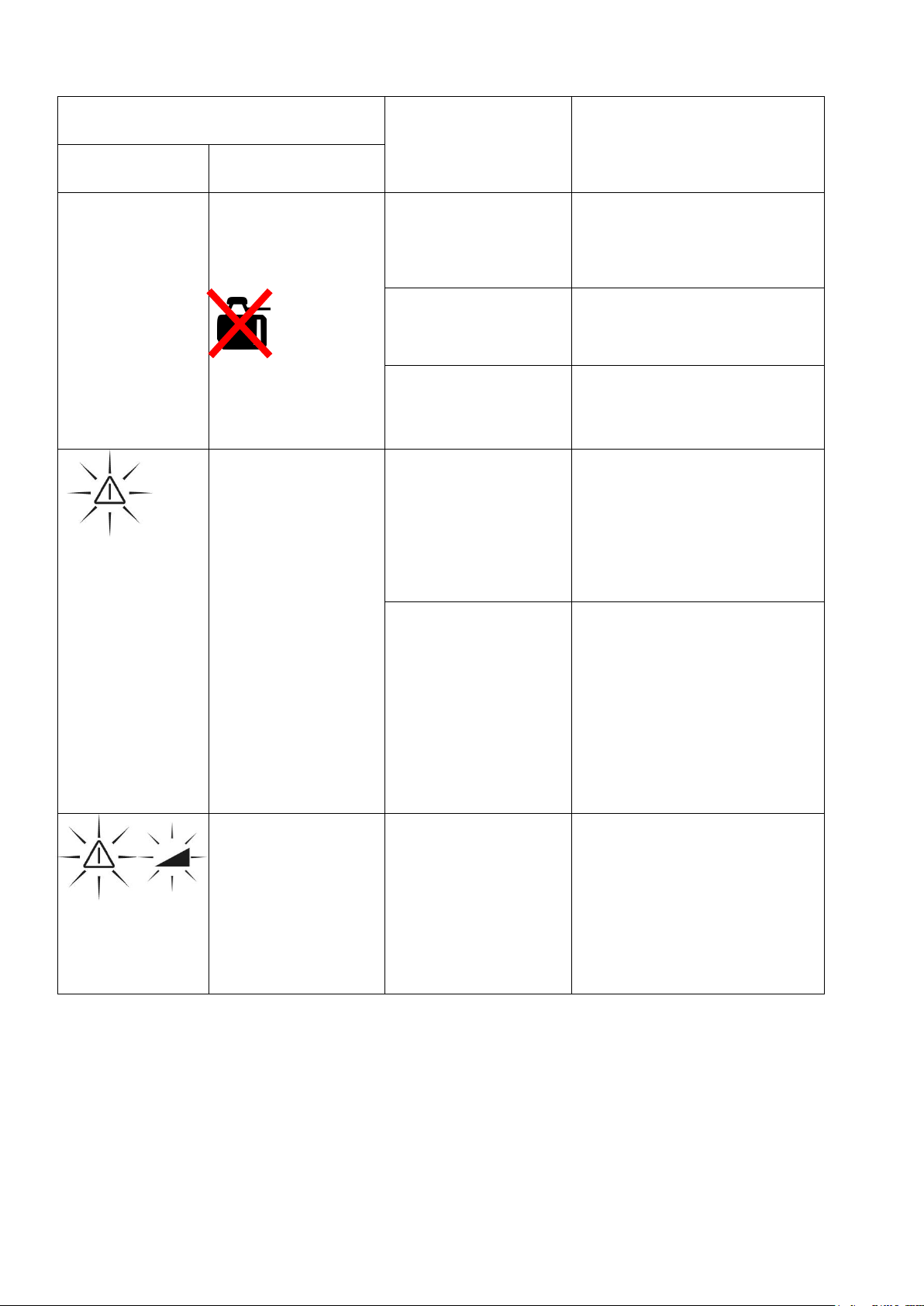
14.3 Error displays
Display
Error
Measure
Laser
Detector
no Conn
A flashes
Device
symbol
Disappears
No wireless
connection
Remove object between laser and detector
Detector
switched off
Turn on the detector
Range exceeded
Place detector closer
to the laser
ALIG FAIL
Rotor stop
Laser beam
flashes
Err
Incorrect
Detector orientation
Detector turns or
Change detector
alignment using the
detector menu
page 55
Max. search
range of 15%
exceeded.
Horizontal:
Slope of the ground
too great. Measurement not possible
Vertical:
Align laser better
Err
Laser has
been activated
by accident
Switch off the laser
and check the alignment.
Restart measurement completely
Table 5: Error description
62
Page 63
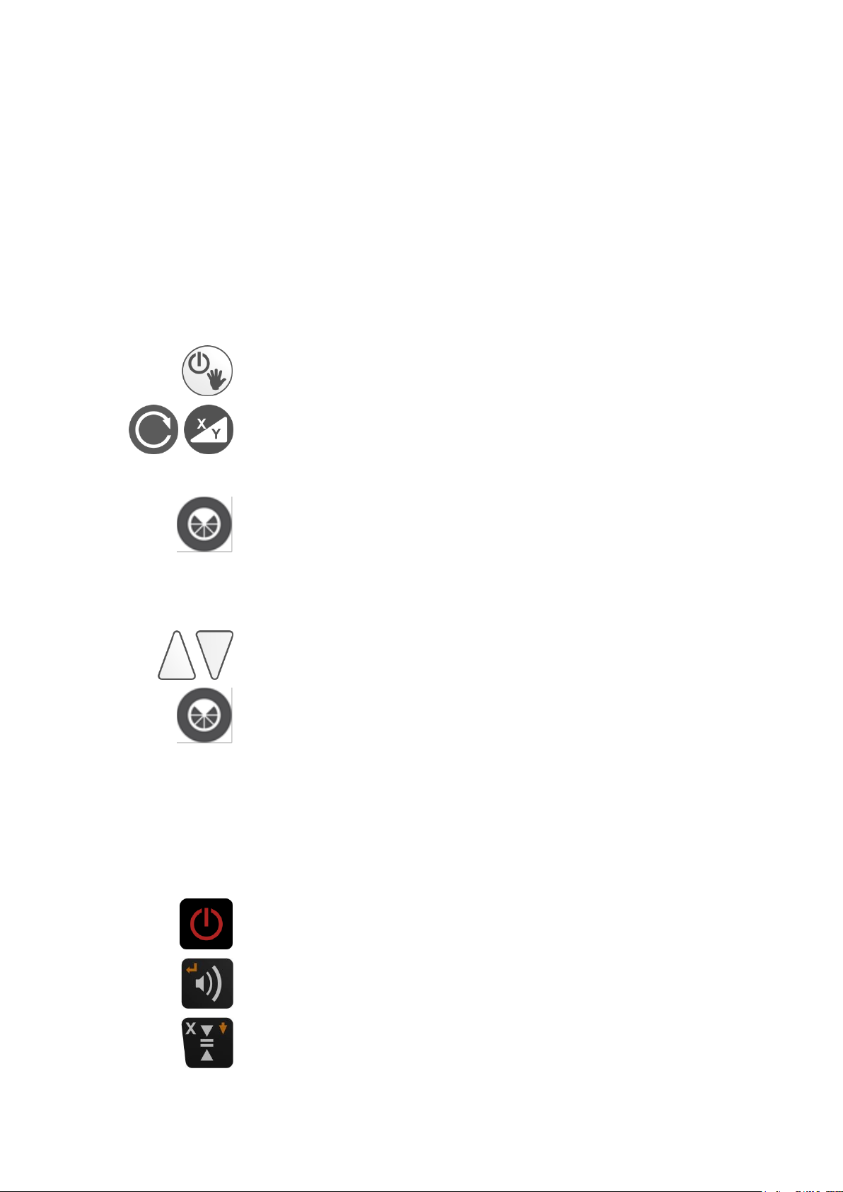
15. Pairing of laser und detector
Switch on the laser
Press for five seconds
InFo
INFO- display
Press for three seconds
ALIG
CHAn
ALIGN channel selection
Select channel 0 – 35.
Start pairing
ALIG
PAIr
Display flashing, Laser wait for TE 90 ALIGN
Settings TE90 ALIGN
Switch on detector
Press for 3 seconds until the menu opens
Press twice
rdo
…occurs in the menu
Attention:
The pairing between the laser and the detector is performed at
the factory and should only be performed by the user if at least
two ALIGN systems are used at the same time and interference
occurs.
In this case, the frequency of laser and detector must be adjusted as follows.
Settings Laser
63
Page 64
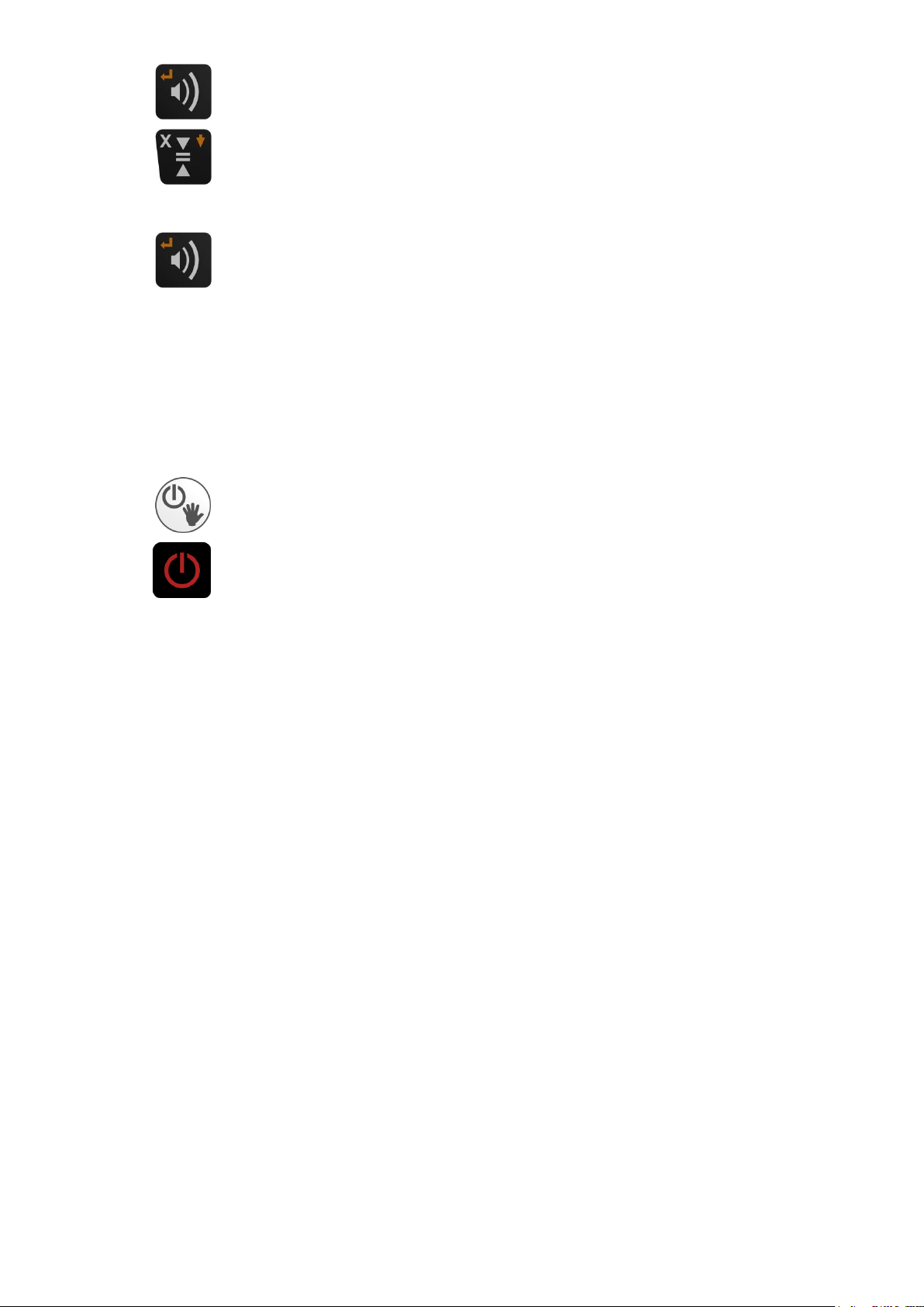
Select menu item
Press until menu item…
PAr
...occurs
Select
Ok
Pairing successful
Complete pairing
9500
XXXX
Serial number of TE 90 ALIGN appears on the laser
display
Turn off the laser
Press 3x: switch detector off
Now the laser and detector are paired to the chosen frequency.
64
Page 65
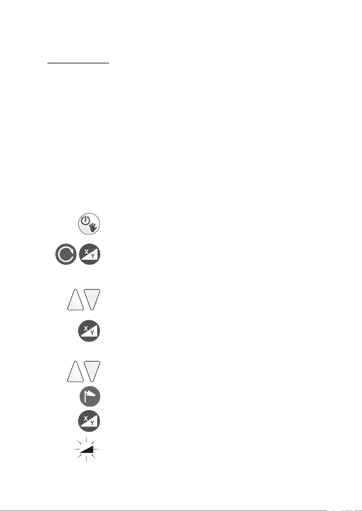
16. Calibration Check
Switch on the laser
Press for five seconds
InFo
INFO- display
e.g. 1.5 CPU (Program Version)
Sn. (Factory number, 6 digit)
h (Operating hours)
Next menu item
Fb CH9 EU
Automatic channel selection or set manually
Select channel CH 1 – 16. (AUTO: Reserved for auto-matic selection) Wireless off: OFF
Activate frequency selection (press for 5 sec.)
Save and next menu item
% / ‰ - setting
Set up the laser leveller as described in point 1 (but on an
extremely well aligned tripod) and align it along a traverse length
of approximately 30 metres – starting with the X axis, for example
– and switch it on.
At the end of the traverse length, make a mark at the level of the
laser beam. After this, rotate the laser unit by 180° and make
another mark. Then do the same for the Y axis. If all the marks
are on top of each other or are only slightly apart (maximum of 2
mm), adjustment is OK. If the marks are a long way apart, you
must get a specialist firm to check the equipment and recalibrate
it.
17. Menu
Information and settings
65
Page 66
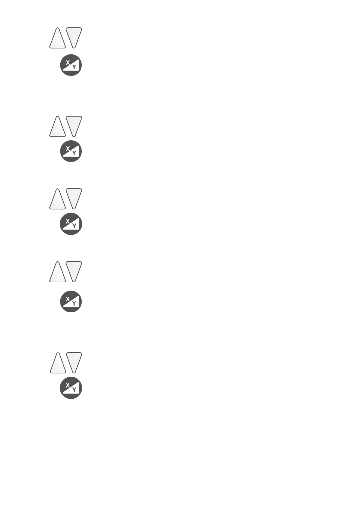
% setting (% setting is default)
‰ - setting
Save and next menu item
dEF
rPM
600
Select start rotation speed
Select 600, 800 or 1000 rpm
Save and next menu item
Lcdb
SEC. 20
Display of lighting timeout
Select 0 – 250 sec
Save and next menu item
Lcdb
Lich120
Display of lighting intensity
Select 0 - 250
Save and next menu item
SLP
hour
1
Standby-/Sleep-function set time
Deactivated at “0”-value
Choose 0…10 hours
Save
66
Page 67
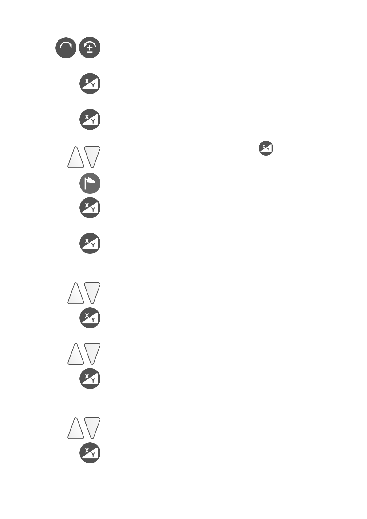
Information and settings FB – V
Press buttons
e.g. 144522
Serial number
Next menu item
e.g. build 089
Program Version
Next menu item
e.g. CH5 EU
Automatic channel selection or select manual
Select channel 1 - 16 and confirm .
(Channel CH Auto is for automatic selection.)
EU
Select US (Attention: Only for USA and AUS)
Save and next menu item
e.g. UbAt2.52
Battery voltage FB - V
Next menu item
APO
e.g. 60 SEC
Automatic shut off FB - V
Select 5 – 600 seconds (60 sec. is default)
Save and next menu item
e.g. Lich140
Display of lighting intensity
Select 0 – 250
Save and next menu item
Lich
e.g. 20 SEC
Display of lighting time out
Select 0 – 600 seconds
Save
67
Page 68

18. Delivery Contents
Standard Option
Laser Radio remote control FB – V
Rechargeable batteries Sighting telescope
(4 Mono-cells) Detector
Power supply unit Tripod
Instruction Manual
Protective case
19. Special Indications and Troubleshooting
Displayed:
Send the equipment for inspection only to an authorized service
partner or directly to the manufacturer.
20. Warranty
We guarantee our products to be free from faults in material and
workmanship according to the current state of the art. Should
defects of this type arise in practical use, they will be eliminated free
of charge. The warranty period is 36 months (apart from the
rechargeable battery, which is 1 year) from the date of sale (date of
invoice). You must return the device or its affected components for
repair or replacement to THEIS immediately after you establish the
defect.
No guarantee claim or claim free elimination of faults due to
incorrect handling or storage can be accepted; in addition, no
claims for damages can be accepted, including claims for damages
in particular claims for indirect damages. Furthermore, any and all
claims for damages will be void in the case of any technical
intervention by third parties, i.e. not by THEIS.
68
Page 69
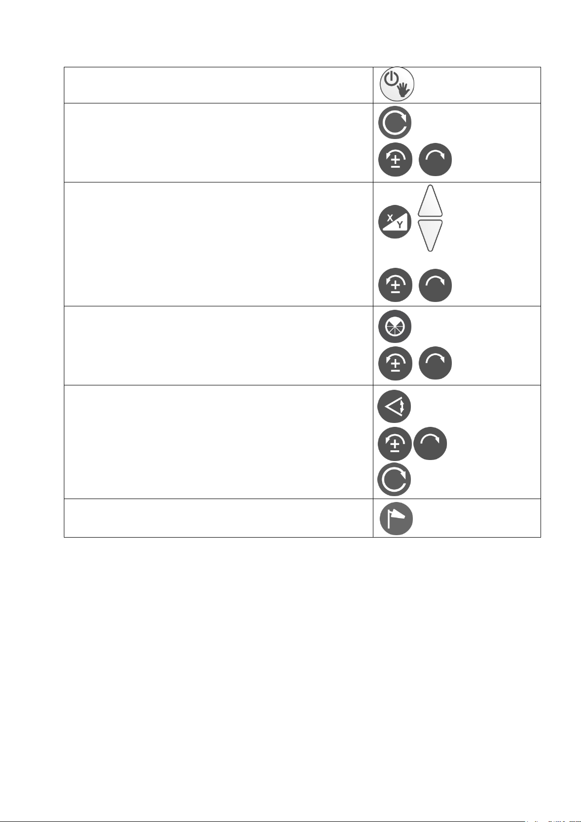
21. Brief Instructions
Switch on/off
Manual mode (press for 5 sec.)
Speed On/ Off
5 steps: 0 - 800
Traversing the laser beam (step mode)
Slope
Display of last input
Input X
Input Y
Confirmation
Change sign and digits
Mask mode
Activation of 90 to 270°: Deactivation
Positioning the mask area
Scanning mode
5 steps 10 to 80°
Positioning the laser line
Deactivate Scan-Mode
Windy
Setting of re-adjustment
69
Page 70

22. Technical Data
Laser
Laser Class / High Power
2 / 3R
Wavelength
635 - 660nm
Output Power / High Power
< 1mW / < 5mW
Range
See detector
Self-levelling range
± 5°
Levelling precision
3,4
± 1,5 mm / 30 m
Grade accuracy
3,4,5
± 0,1% to 5% Grade
Slope X,Y / Align - Horizontal X,Y
± 10% / ± 15%
Align - Vertical (search area)
≈ 9°
Speed
0 – 800 RPM, 4-step, counterclock-
wise/ clockwise rotation in step mode.
Scanning mode
5-step, counterclockwise/clockwise
rotation in step mode.
Mask mode
90 - 270° and positionable
Power supply
NiMH
+
4x 1.2 V, 8Ah
or 4x 1.5V alkaline mono-cells
Running time rechargeable
battery/battery
2,3
≈ 70h / 120h
Charging time
≈ 6h
Working temperature
-15 to + 50°C
System of protection
IP 67 waterproof
Weight
≈ 3 kg
Radio remote control
Range
1,2,3
≈ 200 m
Detector TE 90 ALIGN
Detector field
90 mm
Numeric display
80 mm
Laser - Range with basic unit
1,3
350 m
Laser - Range with High Power
1,3
750 m
Range ALIGN - Function
1,3,6
> 80 m up to 200 m
Precision: Fine / Coarse
see Table 1
Display
2 x LCD / 3 x LED
mm - Display
yes
Power supply
1 x AA
Running time
2,3
> 45 h
Operating temperature
-10°C … +50°C
System of protection
IP 67
Size
135 x 69 x 25 mm
Weight
≈ 190 g
1) Under optimum atmospheric conditions 2) Under optimum conditions
3) At 20°C 4) Parallel to the main X, Y axes
5) Without lateral slope 6) Depending on the orientation of the laser
70
Page 71

23. Supplier Declaration/Safety Information
The device complies with European Directives:
2004/108/EG, RTTE 1999/5/EG sowie 2011/65/EU
Harmonized standards:
EN 60950-1, EN 61000-6-3, EN301489-1, EN300220-1 V2.4.1,
EN 61000-6-2, EN301489-3 und EN300220-2 V2.4.1
A safety information plate is on the left-hand side of the device
An embedded Class 3R (3B with the High Power version) laser
is installed. This means that when you open the device there is
a possibility of entering the range of power values that are
higher than Class 2 (3B with the High Power version). If
possible, do not point the laser at people. Do not look into the
laser beam even with optical instruments.
There are no parts to maintain or adjust inside the device.
Servicing may only be carried out by authorized persons.
Safety regulations for
THEIS Class 3R HIGH-POWER LASER DEVICES
Users must observe BGVB2 (Accident Prevention Regulations for
Laser Radiation in Germany).
Only trained personnel are allowed to operate this product to
avoid radiation with dangerous laser light.
The laser is subject to Class 3R
Do not remove the warning signs on the device!
Observe and secure the beam path over a large distance!
71
Page 72

Never look into the laser beam or shine it into other peoples'
eyes! This also applies at a large distance from the device!
Always set up the laser such that people cannot be shone on
at eye level (pay attention to reflections).
24. Disposal
The surveying device, its accessories and packaging should be
recycled in an environmentally friendly way.
EU countries only:
Never put electrical tools in domestic refuse!
In accordance with EU directive 2012/19/EC concerning
Waste Electrical and Electronic Equipment and its
transposition into national legislation, measuring
equipment that can no longer be used must be collected
separately and recycled in an environmentally friendly
way. (WEEE - Reg. No. DE 10598800)
Rechargeable batteries:
Never put rechargeable batteries in domestic refuse, a fire or into
water. In accordance with Directive 2006/66EC, defective or spent
rechargeable batteries must be recycled or disposed of in an
environmentally friendly way.
EU countries only:
In accordance with Directive 2006/66EC, non-serviceable THEIS
laser devices or spent rechargeable batteries must be recycled or
can be returned directly to:
THEIS FEINWERKTECHNIK GMBH
Zum Bolzenbach 26
D- 35236 Breidenbach
+ 49 (0) 6465 - 67- 0
+ 49 (0) 6465 - 6725
[email protected]
72
Page 73

73
Page 74

Table des matières
Avant-propos ..................................................................................77
Affectation des touches / Ecran ......................................................78
1. Fonctionnement horizontal .....................................................79
2. Fonctionnement vertical / Mode d'alignement .......................79
3. Vitesse de rotation ..................................................................80
4. Inclinaison ...............................................................................80
5. Inclinaison en mode de fonctionnement vertical ....................81
6. Inclinaison en mode de fonctionnement manuel ...................82
7. Mode « Masquage » ...............................................................83
8. Mode « Scan » ........................................................................83
9. Réglage de la sensibilité du niveau (Windy) ...........................84
10. Fonction TILT ..........................................................................84
11. Alimentation en courant – Laser .............................................85
12. Télécommande radio FB-V (option) ........................................86
13. Récepteur TE 90 ALIGN .........................................................88
13.1 Affectation des touches ....................................................88
13.2 Fonctionnement standard .................................................89
13.3 Alimentation en courant – Récepteur ...............................91
14. ALIGN – Fonctionnement .......................................................92
14.1 ALIGN – Horizontal (Inclination) .......................................92
14.1.1 Installation / Exécution ..............................................92
14.1.2 Utilisation / Affichage ................................................93
14.1.2.1 Inclinaison sur l'axe Y (Figure 1) .......................93
14.1.2.2 Inclinaison sur l'axe Y et X (Figure 1) ...............94
14.2 ALIGN - Vertical (Alignement) ..........................................96
14.2.1 Installation / Exécution ..............................................96
14.2.2 Utilisation / Affichage ................................................97
14.3 Affichage des pannes .......................................................98
15. L’accouplement du laser et récepteur .....................................99
16. Vérification de l’ajustage .......................................................101
17. Menu .....................................................................................101
74
Page 75

18. Contenu de la livraison ......................................................... 104
19. Affichages de statut et perturbations .................................... 104
20. Garantie ................................................................................ 104
21. Instructions succinctes ......................................................... 105
22. Caractéristiques techniques ................................................. 106
23. Déclaration du fournisseur / Consignes de sécurité ............ 107
24. Elimination ............................................................................ 108
75
Page 76

76
Page 77

Instructions de service
FR
Avant-propos
VISION 2N ALIGN
... pour les professionnels de la construction.
Le laser rotatif THEIS VISION 2N ALIGN fixe une nouvelle réfé-
rence dans le domaine des lasers de profil pleinement automatisés.
Il résulte d'une longue expérience et de techniques novatrices.
Le laser de construction de grande qualité se distingue par sa solidité et une très grande précision - Made in Germany - il devrait être
de tous les chantiers.
Pour assurer durablement le bon fonctionnement de votre appareil,
nous vous prions de lire attentivement les instructions suivantes:
1. Ne jamais ranger un appareil dans son coffret lorsqu'il est
mouillé.
2. Vérifier la précision avant chaque utilisation; nous déclinons
toute responsabilité en cas de déréglage de l'appareil.
3. Tenir compte des instructions concernant le traitement de l'accu.
4. La fenêtre de sortie du rayon laser ainsi que la fenêtre de la
sonde du récepteur (option) sont à manipuler avec le plus grand
soin.
77
Page 78
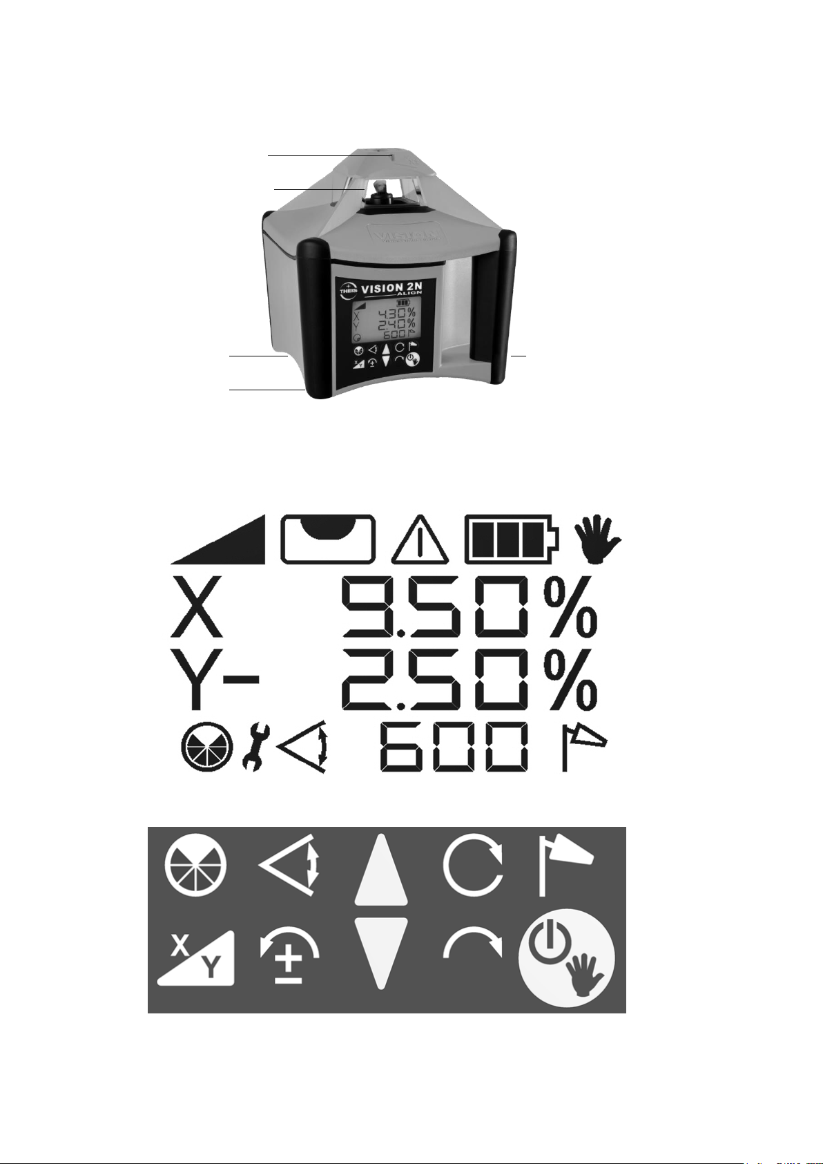
Affectation des touches / Ecran
Inclinaison
des axes
X/Y
Sortie du rayon
laser - Rotation
Prise de
chargement
Compartiment
de l'accu
Viseur optique
Informations produit à
l‘arrière via QR-Code, par
ex. instructions de service
Perturbation
Scan
Inclinaison
Mode de
masquage
Inclinaison
Axes X/Y
Rotation à gauche,
régime pas-à-pas,
Sélection de chiffres
et de signe
Inclinaison
Rotation à droite,
régime pas-à-pas,
Sélection de
chiffres
Marche/Arrêt,
mode manuel
Windy
Régime ou finir scan
Mode
manuel
Affichage
du niveau
Butée finale,
modification de
position
Statut de la
batterie
A
78
Page 79
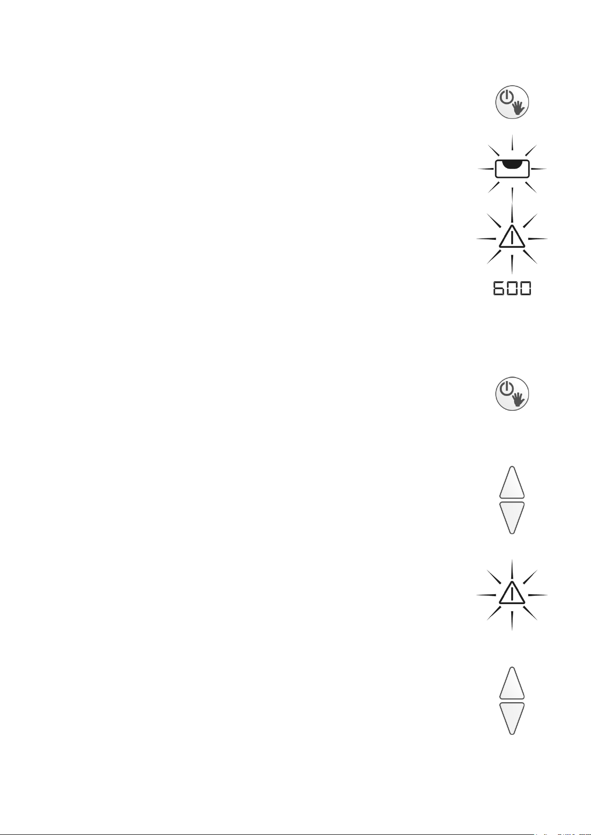
1. Fonctionnement horizontal
Aligner le trépied et fixer le VISION au moyen de la vis
du trépied. La précision d'alignement influence la
grandeur de la plage d'inclinaison. Démarrer l'appareil
au moyen de la touche Marche/Arrêt.
L'affichage du niveau clignote dans l'écran éclairé.
Une inclinaison de la tête du trépied supérieure à 5° est
signalée après un court instant par un clignotement
rapide du rayon laser et du symbole d'alarme.
Dans ce cas, éteindre l’appareil et ajuster
soigneusement le trépied.
Lorsque l'opération de mise à l'horizontale est terminée,
le rayon laser commence à tourner.
2. Fonctionnement vertical / Mode
d'alignement
Placer le laser ou le fixer sur son trépied de sorte que le
clavier soit orienté vers le haut. Le cas échéant, le visser au
trépied au moyen de l'écrou 5/8" arrière. Démarrer le laser
au moyen de la touche Marche/Arrêt. Cf. point 1 pour de
plus amples informations.
Aligner le rayon laser au moyen des touches fléchées. Le
mouvement d'alignement du rayon laser accélère lorsque la
touche fléchée est maintenue enfoncée.
Tout dépassement de la course lors de l'alignement est
signalisé par une modification de l'ordre des barres, un
symbole d'avertissement clignotant rapidement et le rayon
laser.
Les butées finales peuvent à nouveau être déverrouillées
au moyen des touches fléchées.
_ _ _
_ - _
-
_ -
79
Page 80
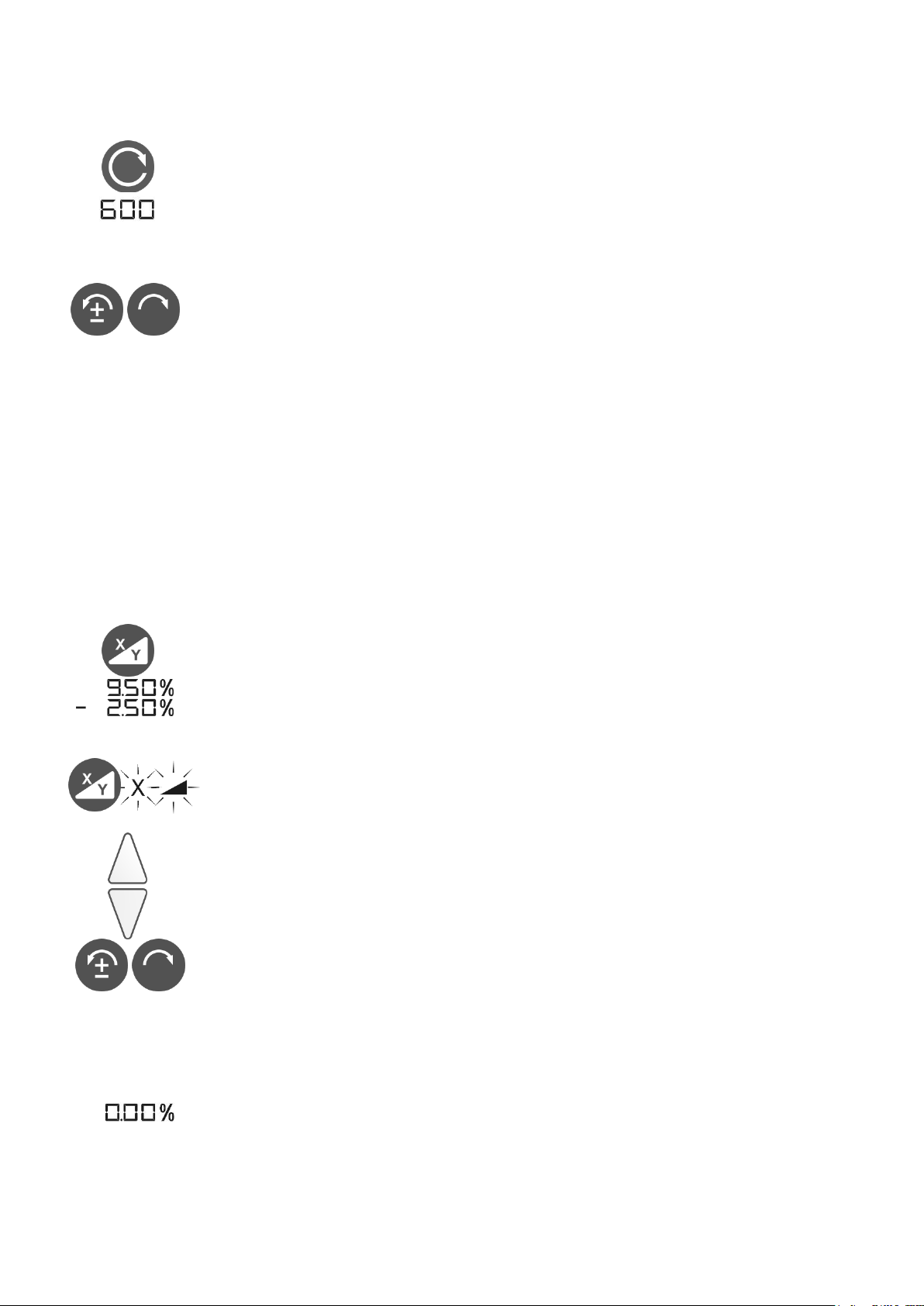
3. Vitesse de rotation
La vitesse de rotation peut être réglée sur 4 niveaux : 0,
200, 600 et 800 tr/min. Appuyer deux fois sur la touche
« Rotation » pour arrêter le laser (vitesse 0). Appuyer à
nouveau sur la touche pour augmenter la vitesse de
rotation.
A l'arrêt, le point laser peut être déplacé au moyen des
touches de rotation à gauche/droite. Lorsqu'une des
touches est maintenue enfoncée, le mouvement du point
laser s'accélère.
4. Inclinaison
Le laser peut – lorsque le trépied est bien aligné – être
incliné de -10% à +10% sur les deux axes.
A cette fin, aligner tout d'abord le laser sur la cible au
moyen du viseur optique, puis saisir les valeurs
d'inclinaison comme suit:
1ère pression sur la touche: activation de l'inclinaison. Les
valeurs enregistrées pour l'inclinaison lors de la dernière
utilisation s'affichent et l'appareil se déplace
automatiquement dans cette position.
2ème pression sur la touche : X, affichage de l'inclinaison
et 1 chiffre de la valeur d'inclinaison clignotent à l'écran.
Régler la valeur d'inclinaison à l'aide des touches fléchées.
Vous pouvez régler chaque chiffre clignotant.
Utiliser les touches rotations à gauche / droite pour accéder au point suivant. Utiliser la touche de gauche pour
modifier le signe (±). Le signe Plus n'est pas affiché.
Un appui prolongé sur les touches fléchées accélère la
modification de la valeur.
Appuyer simultanément sur les touches fléchées pour remettre l'affichage à 0.
80
Page 81
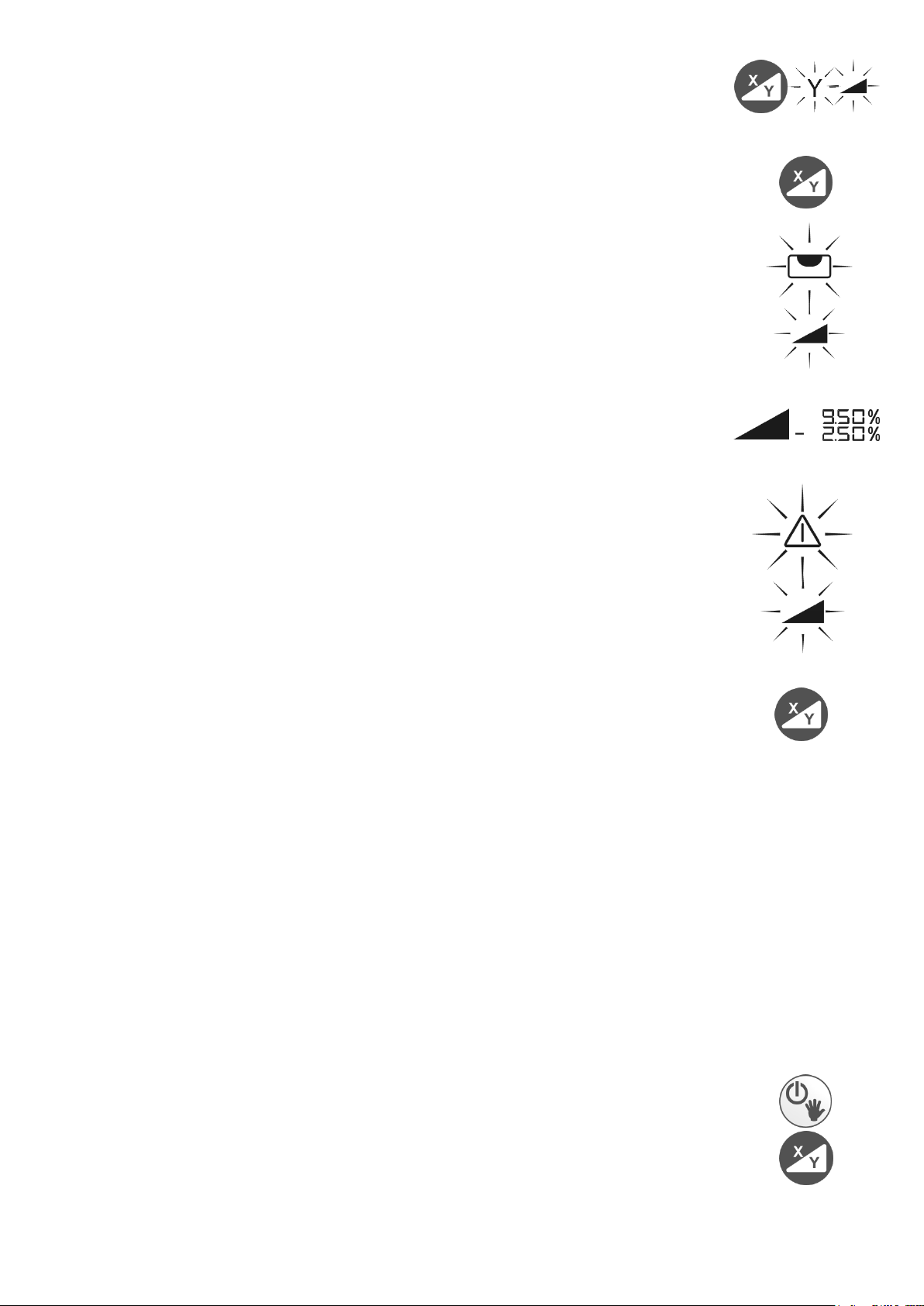
3ème pression sur la touche : Y, valeur d'inclinaison et 1
chiffres de la valeur d'inclinaison clignotent à l'écran.
4ème pression sur la touche: confirmation des valeurs
Une nouvelle mise à niveau commence alors, signalisée
par l'affichage d'un niveau clignotant à l'écran. L'appareil se
déplace ensuite pour atteindre les valeurs d'inclinaison
indiquées.
Pendant cette procédure, le symbole d'inclinaison
clignotant.
Une fois les valeurs atteintes, les valeurs d'inclinaison et le
symbole d'inclinaison restent affichés.
En cas de modification de la position de l'appareil due à des
influences extérieures comme des vibrations ou de grands
écarts de température, le mode Rotation est interrompu
automatiquement. Ceci permet d'éviter les mesures erronées. Le rayon laser, le symbole d'inclinaison et l'affichage
d'avertissement clignotent rapidement sur l'écran.
Appuyer à nouveau sur la touche d'inclinaison permet de
réactiver le mode d'inclinaison, l'appareil se remet à l'horizontale et l'appareil se déplace à nouveau jusqu'aux valeurs enregistrées pour l'inclinaison.
Attention! La position de montage du laser peut
cependant avoir été modifiée, tout comme, le cas
échéant, sa hauteur et sa direction. Par sécurité, il est
donc recommandé d'arrêter et de redémarrer l'appareil
et de le régler à nouveau.
5. Inclinaison en mode de
fonctionnement vertical
Une inclinaison peut également être indiquée en mode de
fonctionnement vertical. Ceci est évidemment uniquement
le cas pour l'axe Y. Appuyer ici sur la touche X/Y. Cf. point
4 pour la description d'autres procédures similaires.
81
Page 82
X
Y
6. Inclinaison en mode de
fonctionnement manuel
Pour, par exemple, pouvoir réglée des plus grandes
inclinaisons au moyen d’une table rectangulaire, le système
automatique de l’appareil doit être désactivé.
Ceci se fait en maintenant la touche Marche/Arrêt enfoncée
(env. 5 sec.). Indication à l'écran par une main clignotante..
Aligner alors tout d'abord le laser précisément sur la cible
au moyen de la lunette de visée ou du viseur optique, puis
indiquer l'inclinaison:
Le symbole d'inclinaison et X sont affichés à l'écran.
Déplacer l'appareil jusqu'à l'inclinaison souhaitée au moyen
des touches fléchées.
2ème pression sur la touche : Le symbole X disparaît et le
symbole d'inclinaison et Y sont affichés à l'écran.
Déplacer l'appareil jusqu'à l'inclinaison souhaitée au moyen
des touches fléchées.
Avec des inclinaisons NEGATIVES (appuyer sur la flèche
en bas), le signe moins (-) est affiché à l'écran. Aucun signe
n'apparaît à l'écran lorsque la flèche vers le haut est enfoncée (plus).
Attention: L'auto-nivellement et l'arrêt automatiques du laser ne sont pas possibles en mode ma-
nuel !
82
Page 83
7. Mode « Masquage »
En mode de masquage, la sortie du rayon laser peut être
limitée dans une zone réglable.
Ceci est uniquement possible lorsque le rayon laser tourne,
et donc pas en mode « Scan ».
Un seul appui active le plus petit masquage possible
(90°), chaque appui supplémentaire augmente la zone
de masquage jusqu'à 270°. Le mode Masquage est
quitté au 4ème appui sur la touche.
La zone masquée est représentée en sombre à l'écran.
Le rayon laser continue à être visible dans la zone
claire. Les touches de rotation à gauche/droite permettent de tourner la zone de masquage dans la direction
souhaitée.
Les touches de rotation à gauche/droite permettent de tourner la zone de masquage dans la direction souhaitée.
8. Mode « Scan »
Un appui sur la touche Scan permet d'accéder au mode
Scan au réglage le plus petit de 10°. Des appuis supplémentaires sur la touche permettent de générer 5 dimensions différentes de ligne laser (10°, 20°, 40°, 60°, 80°) ;
elles sont affichées à l'écran.
Les touches de rotation à gauche/droite permettent de
déplacer la ligne laser en conséquence. Lorsqu'une touche
est maintenue enfoncée, le mouvement de la ligne laser
s'accélère.
La dernière position de la tête du rotor est enregistrée lorsque le mode Scan est quitté à l'aide de la touche Rotation.
Si vous sélectionnez ultérieurement de nouveau le mode
Scan, la ligne laser se déplace dans cette position.
83
Page 84

9. Réglage de la sensibilité du niveau
(Windy)
Si l'appareil est sans cesse déplacé par le vent, des
variations de terrain ou de légers chocs pendant le travail,
interrompant la rotation, il est possible d'obtenir de l'aide
grâce à la fonction Windy.
Appuyer sur la touche Windy permet de réduire la
sensibilité du niveau de l'instrument.
La touche Windy est verrouillé en mode d'inclinaison.
10. Fonction TILT
En cas de modifications plus importantes de la position de
montage (par ex. après le déplacement involontaire du
trépied), une fonction TILT permet de garantir que l'appareil
s'éteint et indique le déplacement par un clignotement
rapide du rayon laser et du triangle d'avertissement.
Il faut ensuite remettre l'appareil en marche.
84
Page 85
11. Alimentation en courant – Laser
L'affichage de capacité de l'accu indique l'état de
l'accumulateur sur 4 niveaux.
Lorsque les 3 barres de l'affichage sont vides et le cadre
extérieur clignote, la capacité est épuisée et l'accu doit être
chargé. Si ce n’est pas le cas, l’appareil s’arrête
automatiquement après un certain temps.
Les 3 barres clignotent de manière ascendante pendant le
chargement. Lorsque l'accu est plein, toutes les barres
s'affichent.
Ne procéder au chargement de l'accumulateur à température
ambiante qu'au moyen du chargeur standard THEIS raccordé à
la prise de chargement placée sous le laser. Un chargement
sous +5°C peut entraîner des dommages à l’accu.
Il est également possible de procéder au chargement pendant
le fonctionnement. Aucune surcharge n'est possible.
Utiliser uniquement le chargeur dans des locaux
parfaitement secs !
Les accumulateurs utilisés, dotés de la technologie
Eneloop™ offrent l'avantage de se décharger très peu
lorsqu'ils ne sont pas utilisés.
Les accumulateurs n'étant pas utilisés ne doivent donc
être rechargés que tous les 6 mois.
Des piles alcalines normales peuvent également
être utilisées dans le compartiment de l'accu. Celles-ci ne
doivent en aucun cas être rechargées. Si cela devait cependant
arriver par mégarde, le symbole de la batterie clignote.
Attention ! Respecter les polarités ! Des symboles ± sont
placés au fond du compartiment de l'accu. Respecter les
consignes d'élimination du point 23.
Attention: Les bornes et contacts des batteries pouvant s'encrasser au fil du temps et générer des problèmes de contact, il est im-
pératif de les contrôler et nettoyer, si nécessaire, régulièrement
avec un chiffon doux et un détergent (alcool à brûler, alcool).
85
Page 86
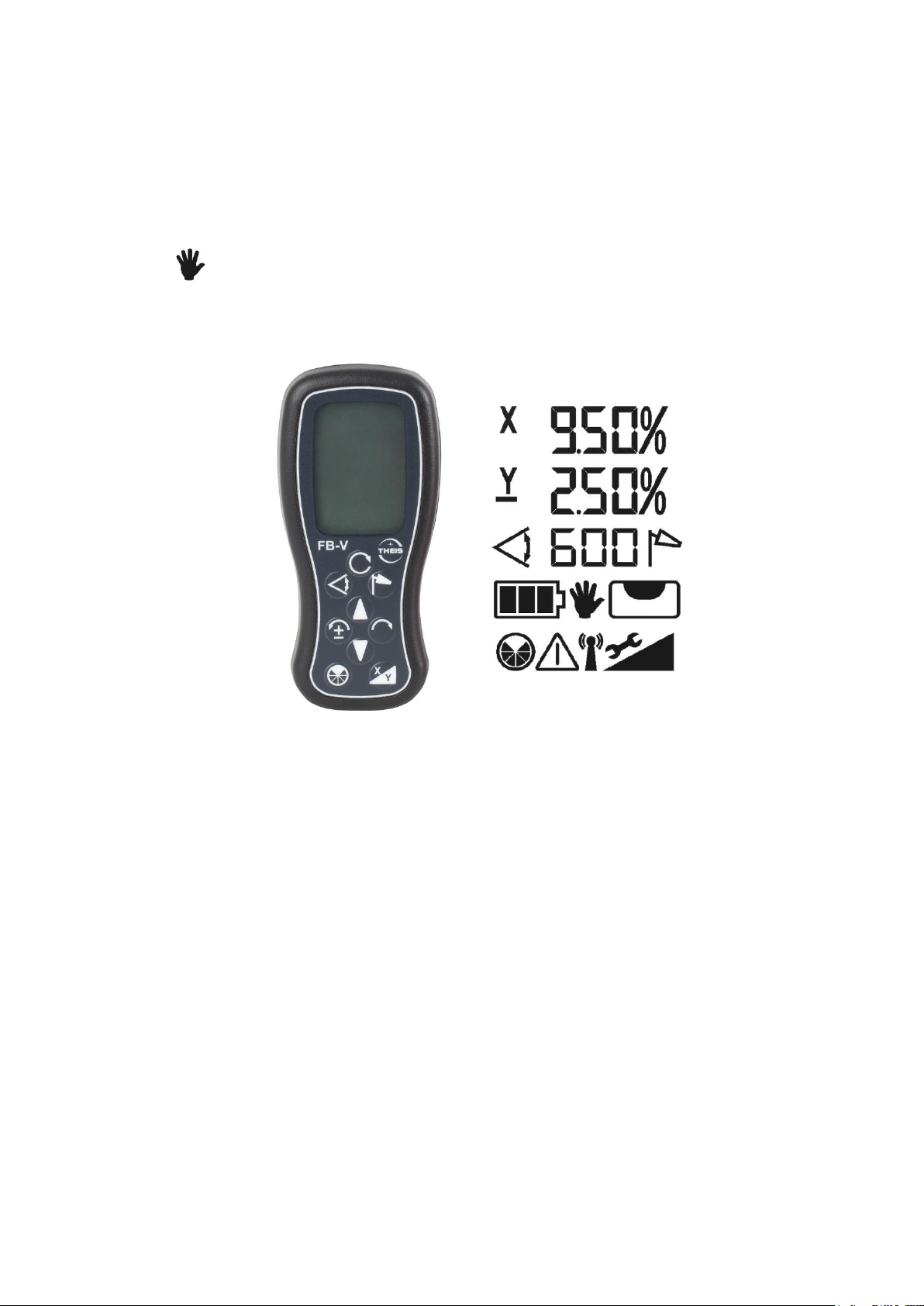
12. Télécommande radio FB-V (option)
La télécommande radio est conçue de manière bidirectionnelle.
Toutes les informations s'affichant à l'écran du laser apparaissent
également sur l'écran éclairé de la télécommande. Les symboles
des touches sur le champ de commande correspondent aux
touches sur le clavier du laser. Le mode de fonctionnement
MANUEL n'est pas disponible pour éviter toute sélection
intempestive de cette fonction.
Die FB-3 durch Drücken einer beliebigen Taste einschalten. Die
Démarrer la télécommande FB-V en appuyant sur une touche au
choix. La télécommande recherche automatique un canal adéquat
pour exclure toute interférence avec d'autres appareils.
Les mêmes indications apparaissent sur l'écran de la télécommande
que sur l'écran du laser correspondant. Si ce n'est pas le cas et si un
symbole d'antenne s'affiche, les raisons peuvent en être les suivantes:
- Le laser n'est pas démarré.
- Le canal radio n'est pas correctement réglé.
- La télécommande se trouve hors de portée du laser
Le laser peut être éteint en enfonçant simultanément les deux
touches fléchées. Le FB-V s’éteint automatiquement après 1
minute.
86
Page 87

Si la fonction « Standby-/Sleep » est activée sur le laser, pour
économiser la capacité de la batterie (voir chapitre 17), il peut être
mis en veille en appuyant simultanément sur les deux touches
fléchées de la télécommande. Pour quitter le mode veille appuyez
sur n’importe quelle touche de la télécommande et l’appareil
reprend son fonctionnement normal, comme après sa remise sous
tension. La durée maximum de veille peut être réglée dans le menu
info (voir chapitre 17). Si le temps d'attente est dépassé, le laser
s'éteint.
L'alimentation en courant se fait au moyen de deux piles alcalines
Micro AAA. La durée de fonctionnement est d'env. 60 heures.
Le symbole de la batterie indiqué l'était des piles du FB-V.
Pour remplacer les piles, ouvrir le couvercle à l'arrière de la
télécommande et procéder au remplacement. Respecter les
polarités. Cf. point 23 pour les consignes d'élimination.
87
Page 88
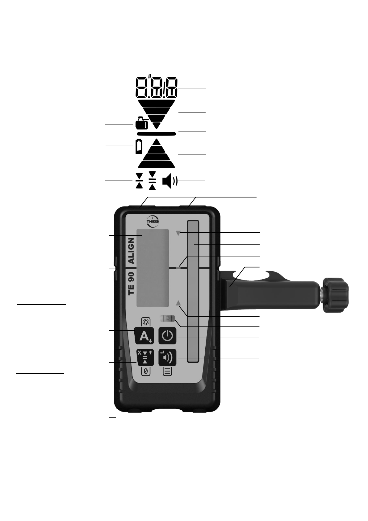
13. Récepteur TE 90 ALIGN
Affichage de direction à LED
LED « Centre »
Fenêtre de la sonde
Affichage de direction à LED
Niveau tubulaire à bulle d'air
Touche MARCHE / ARRÊT
Touche « Signal sonore » /
Menu: Touche de confirmation
Aimant
Écran
(également sur la face arrière)
Encoche centrale
Touche
Pression courte:
Marche / arrêt « Align »
Pression longue:
Marche / arrêt « LED »
Menu: Touche fléchée vers le
Touche
Pression courte:
Précision de l'affichage
Pression longue:
Marque de référence
ALIGN horizontal: axe X
Menu: touches fléchées vers
le bas
Pince de fixation
Précision de l'affichage
Indicateur « Batterie »
Indicateur « Signal acoustique »
Flèche pour le sens de déplacement
Barre centrale
Flèche pour le sens de déplacement
Affichage numérique / textuel
Compartiment à batterie
(face arrière)
Symbole de l'appareil :
raccordé au laser
13.1 Affectation des touches
88
Page 89

13.2 Fonctionnement standard
mm
cm
pouce
pouce/
fraction
Écran
Très fin
0,5
0,05
0,02
-
Clignotant
Fin
1,0
0,1
0,05
1/8
Allumé en
permanence
Moyen
2,0
0,2
0,1
1/4
Allumé en
permanence
Grossier
5,0
0,5
0,2
1/2
Allumé en
permanence
Très
grossier
10,0
1,0
0,5
-
Clignotant
Marche / Arrêt de l'appareil
Appuyer sur la touche Marche / Arrêt
Adaptation du volume
Une pression longue sur la touche du signal sonore permet
d'adapter le volume : Faible / Fort / Muet
Fort : le symbole du haut-parleur reste affiché en
permanence ; affichage « Hi » pendant une seconde
Faible : le symbole du haut-parleur reste affiché en
permanence ; affichage « Low » pendant une seconde
Muet : le symbole du haut-parleur n'est pas affiché ; affichage
« OFF » pendant une seconde
Réglage de la précision d'affichage
Appuyer une fois sur la touche « Précision d'affichage » pour voir le
réglage actuel à l'écran. Appuyer à nouveau sur la touche tant que
la valeur est affichée (dans la seconde) pour modifier la précision.
Appuyer aussi souvent que nécessaire sur la touche jusqu'à ce que
le réglage souhaité apparaisse.
Tableau 1: Précision
89
Page 90

Activation / Désactivation des LED
Appuyer sur la touche « Affichage LED » pour modifier l'affichage
LED. Lorsque cette option est activée, les valeurs de mesure sont
affichées au moyen de LED en plus de l'affichage à l'écran.
Hauteur de consigne définie par l'utilisateur
Une hauteur de consigne au choix (point zéro) peut être définie
entre -10 et +40 mm autour de l'encoche centrale. Pour cela, maintenir la touche « Précision d'affichage » enfoncée pendant deux secondes pendant la réception laser. Un signal de confirmation retentit lorsque la manipulation a réussi et le symbole d'une flèche asymétrique apparaît à l'écran. Si le rayon laser se trouve en dehors de
la zone autorisée, un signal d'erreur retentit et l'écran affiche l'erreur
E30. Pour réinitialiser la hauteur de consigne, maintenir la touche
« Précision d'affichage » enfoncée pendant deux secondes en l'absence de réception laser. La hauteur de consigne est automatiquement réinitialisée lorsque l'appareil est mis à l'arrêt.
Utilisation du menu
Le menu permet de modifier différents réglages. Les réglages par
défaut sont idéaux dans la plupart des cas. Nous recommandons
de ne modifier les réglages que pour les applications spéciales.
Appuyer sur la touche « Signal sonore / Confirmation » pendant
plus de deux secondes pour accéder au menu.
Les entrées du menu (p.ex. SEn) restent affichées et il est pos-
sible de les faire défiler au moyen des touches fléchées.
Sélectionner une entrée du menu en appuyant sur la touche
« Signal sonore / Confirmation ».
Les options (p.ex. On) clignotent et il est possible de les modifier
au moyen des touches fléchées.
Quitter le menu en appuyant sur la touche « Marche / Arrêt ».
Entrées du menu :
SEn - Sensibilité : Élevée (Hi) / Faible (Low)
Par défaut : élevée. En cas de problèmes causés par des tubes
fluorescents et des flashs, p.ex., il peut être utile de définir ce
réglage sur « Faible ».
90
Page 91

AvG - Moyenne : Élevée (Hi) / Faible (Low)
Par défaut : faible. Définir le réglage sur « Élevée » lorsque des va-
leurs plus stables sont requises dans des conditions atmosphériques difficiles.
Unt - Unité de mesure : mm / cm / pouce (in) / pouce en
fractions (f.in)
Par défaut : mm. Sélectionner l'unitré de mesure souhaitée.
o.o.b - Perte du rayon laser : Marche (On) / Arrêt (OFF)
Par défaut : arrêt. Activer et désactive l'affichage pour la perte du
rayon laser. Une séquence de flèches indique que le laser a quitté
la zone de réception. La flèche indique dans quelle direction l'appareil doit être déplacé pour retrouver le rayon laser.
Inf - Informations relatives à l'appareil
Cette entrée reprend des informations sur le logiciel de l'appareil
(Fw), le type d'appareil (dc) et le numéro de série (Sn).
ALG – Alignement du récepteur avec la fonction ALIGN
Par défaut : « Hor » « UP » / « Ver » « UP ». Réglage « UP »
et “dwn” possible.
Réglage „UP“ horizontal: Écrit „THEIS“ par Logo droit lisible
Réglage „UP“ vertical: Écrit „TE 90 ALIGN“ Logo droit lisible
REMARQUE : Tous les réglages du menu sont conservés
lorsque le récepteur est arrêté.
13.3 Alimentation en courant – Récepteur
La batterie (1xAA) doit être remplacée lorsque le symbole de la batterie
apparaît dans l’écran LCD; dans le cas contraire, la portée de l’appareil
peut être limitée.
Ouvrir le couvercle rabattable du logement de batteries et procéder à
l'échange.
Eliminer les anciennes batteries dans le respect des directives en vigueur (cf. point 24) et respecter la polarité lors de la mise en place des
nouvelles batteries (voir symboles).
91
Page 92
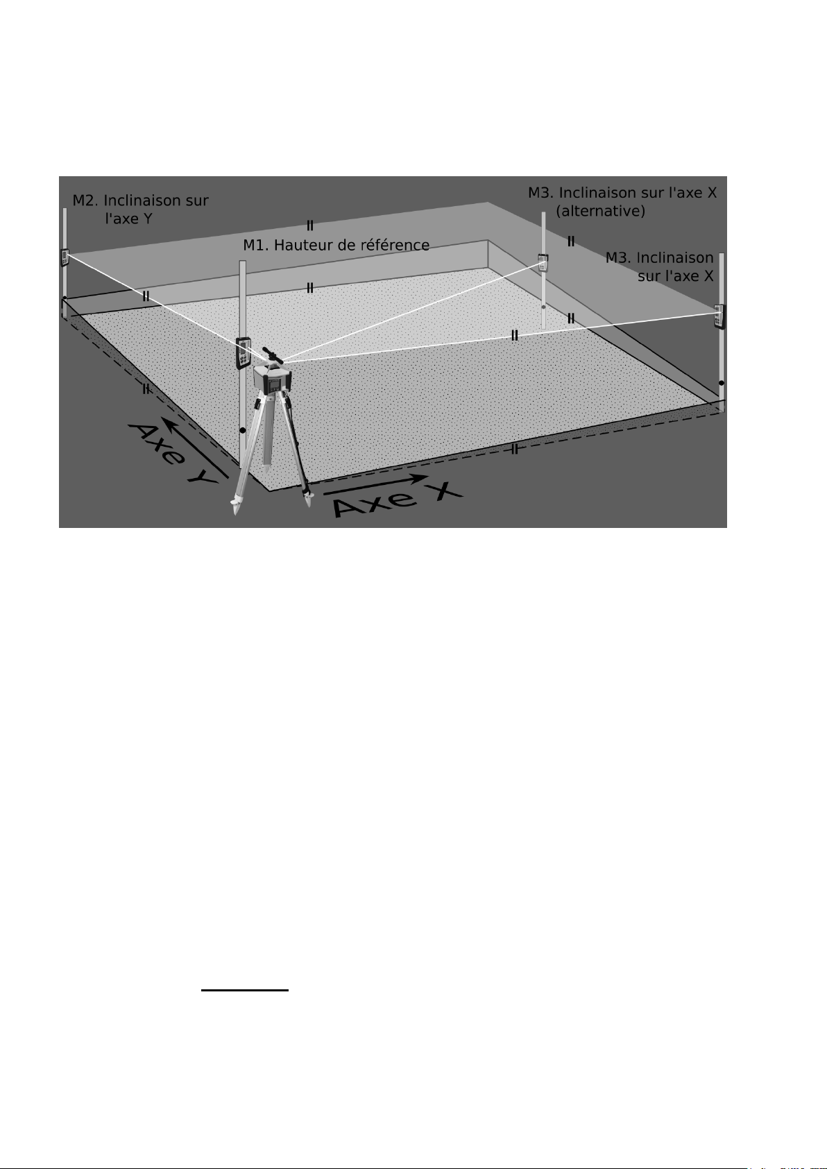
14. ALIGN – Fonctionnement
14.1 ALIGN – Horizontal (Inclination)
14.1.1 Installation / Exécution
Figure 1: Installation de l'ALIGN à l'horizontale
Le système laser Vision 2N ALIGN et le récepteur TE 90 ALIGN
permettent de régler automatiquement 2 inclinaisons sur les
axes X et Y.
Le chapitre 4 décrit tout d'abord comment placer la tête du trépied
parfaitement à l'horizontale et aligner le laser sur la première cible
M2 (Figure 1) dans l'axe Y. La lunette de visée (option) doit être utilisée lorsque les valeurs d'inclinaison déterminées doivent être les
plus précises possibles.
Placer ensuite la mire laser graduée avec le récepteur le plus près
possible du laser (Figure 1 : hauteur de référence M1) et démarrer
les deux appareils comme décrit aux chapitres 1 et 13.2, puis placer le centre du récepteur à la hauteur du rayon laser.
Cette cote servira de hauteur de référence pendant toute la
mesure et ne pourra plus être modifiée.
Placer le récepteur / la mire laser graduée sur le point de mesure
M2 et noter la première inclinaison sur l'axe Y. (cf. Tableau 2)
92
Page 93
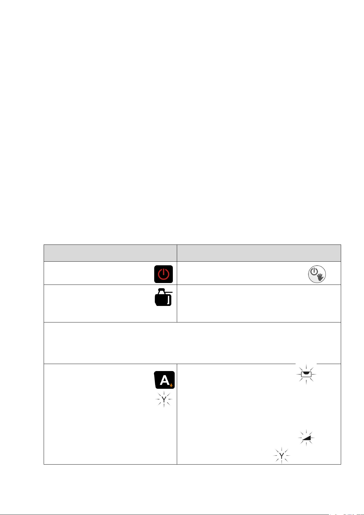
Attention !
TE 90 ALIGN
VISION 2N ALIGN
Allumer le récepteur.
Allumer le laser.
Le symbole de l'appareil doit toujours être
affiché.
Réglage du récepteur à une courte distance du laser à la référence
de hauteur. Placer le récepteur sur la cible M2. M2 doit se trouver
précisément sur l'axe Y du laser (Lunette de vi sée recommandée).
Axe Y
Appuyer brièvement
sur la touche A.
Le système ALIGN
démarre dans l'axe Y.
Le laser atteint le
commutateur de fin
de course et procède au nivellement.
Nivellement achevé.
Le laser recherche
le récepteur.
0.00% A
Pour obtenir des valeurs d'inclinaison précises, le premier
point d'enregistrement de l'inclinaison doit se trouver précisément sur l'axe Y du laser. La lunette de visée disponible auprès de THEIS est vivement recommandée ici.
Remarque !
(1) La vitesse de rotation et les zones de masquage peuvent
changer pendant la recherche du récepteur.
(2) Il ne peut y avoir aucun objet gênant entre le laser et le récep-
teur ; dans le cas contraire, ceci peut influencer la vitesse de
recherche et rendre la localisation difficile.
(3) Si un second récepteur normal doit être utilisé dans le statut
du système ALIGN, p.ex., pour déterminer des points intermédiaires, il faut ici veiller à ce que ce récepteur ne recouvre pas
le champ de réception du TE 90 ALIGN, mais soit au-dessus
ou en dessous de celui-ci. Ceci pourrait fausser les résultats.
14.1.2 Utilisation / Affichage
14.1.2.1 Inclinaison sur l'axe Y (Figure 1)
93
Page 94
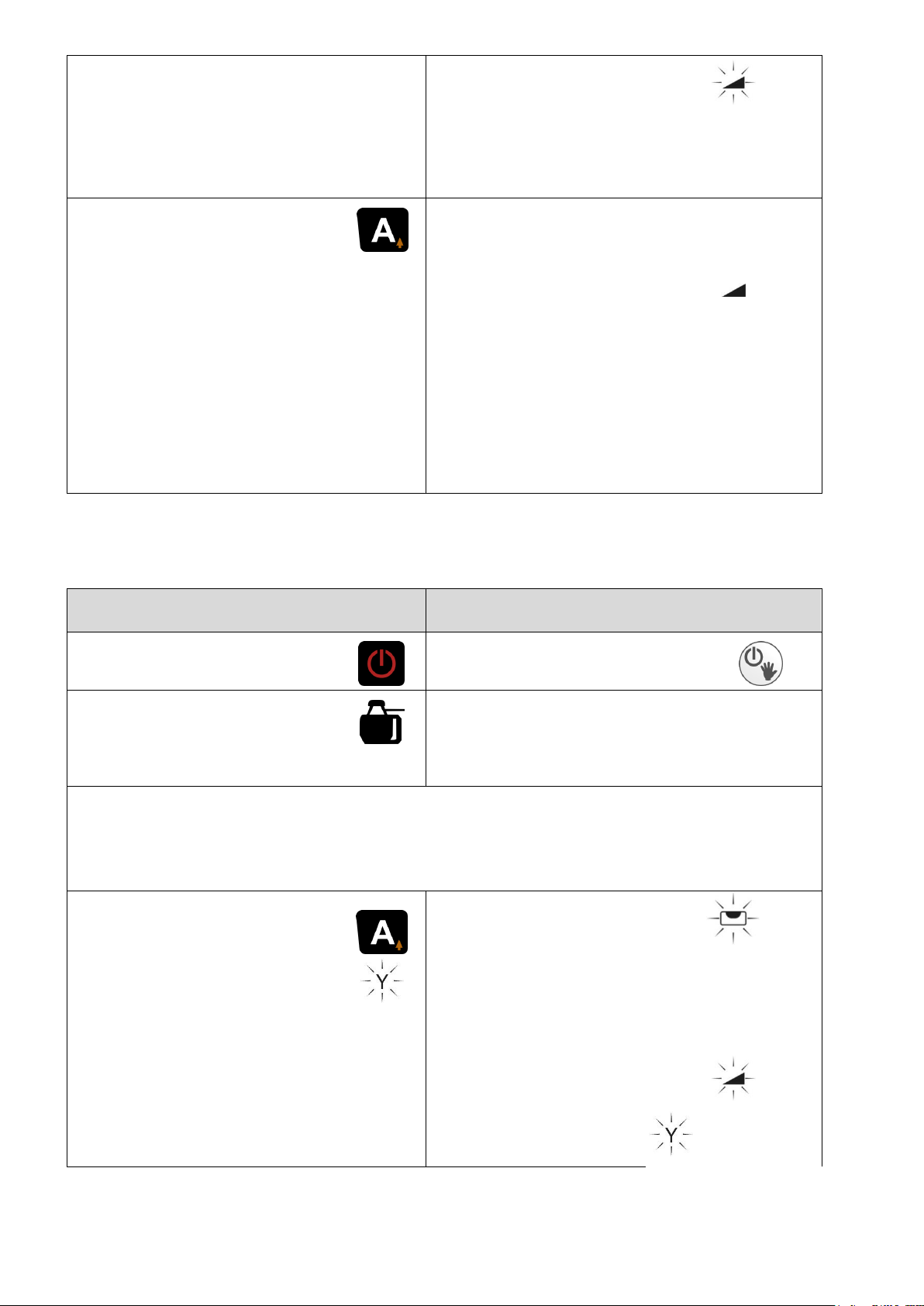
Tableau 2: Fonctionnement horizontal du système ALIGN sur l'axe Y uniquement
Recherche achevée :
Y ou –Y et la valeur d'inclinai-
son _._ _ clignotent en alternance.
Récepteur trouvé.
Y
_._ _% A
Arrêt du système
ALIGN :
Appuyer brièvement
sur la touche A.
Le système ALIGN est
désactivé.
Le récepteur passe
alors en mode de fonctionnement standard et
peut être retiré.
La poursuite du
récepteur s'arrête.
La valeur d'inclinaison Y est enregistrée.
Le laser passe en
fonction d'inclinaison standard.
Y
_._ _%
TE 90 ALIGN
VISION 2N ALIGN
Allumer le récepteur.
Allumer le laser.
Le symbole de l'appareil doit toujours être
affiché.
Réglage du récepteur à une courte distance du laser à la référence
de hauteur. Placer le récepteur sur la cible M2. M2 doit se trouver
précisément sur l'axe Y du laser (Lunette de visée recommandée).
Axe Y
Appuyer brièvement
sur la touche A.
Le système ALIGN
démarre dans l'axe Y.
Le laser atteint le
commutateur de
fin de course et
procède au nivellement.
Nivellement achevé. Le laser recherche le récepteur.
0.00% A
14.1.2.2 Inclinaison sur l'axe Y et X (Figure 1)
94
Page 95
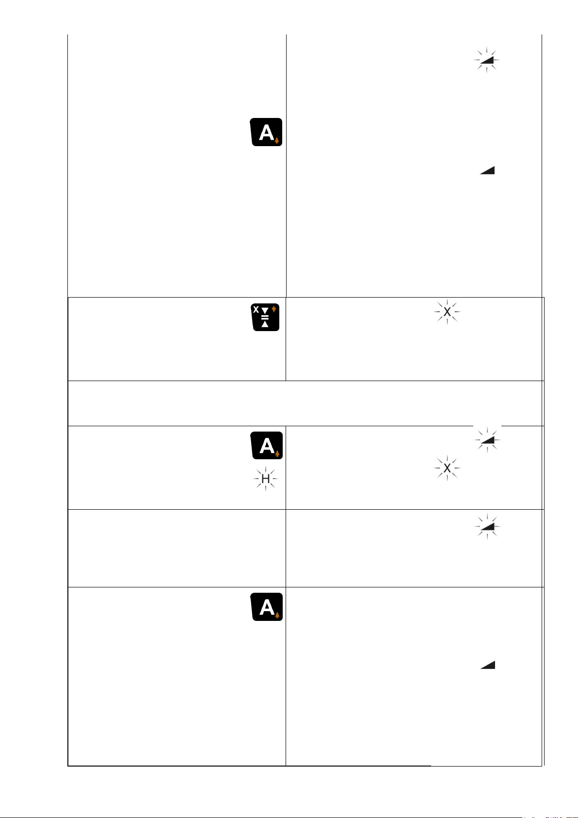
Recherche achevée :
Y ou –Y et la valeur d'inclinaison _._ _ clignotent en alternance.
Récepteur trouvé.
Y
_._ _% A
Arrêt du système
ALIGN :
Appuyer brièvement sur
la touche A.
Le système ALIGN est
désactivé.
Le récepteur passe
alors en mode de fonctionnement standard et
peut être retiré.
La poursuite du récepteur s'arrête.
La valeur d'inclinaison Y est enregistrée.
Le laser passe en
fonction d'inclinaison standard.
Y
_._ _%
Axe X
Appuyer sur la touche
« Précision d'affichage /
X ».
H
La valeur d'inclinaison Y est enregistrée.
0.00%
Y
_._ _% A
L'inclinaison sur l'axe Y n'est maintenant plus ajustée.
Placer le récepteur sur la cible M3 pour l'inclinaison X.
Appuyer brièvement sur
la touche A :
Le système ALIGN démarre pour l'axe X.
Le laser recherche
le récepteur.
0.00%
Y
_._ _% A
Recherche achevée :
X ou –X (H ou –H) et la valeur
d'inclinaison _._ _ clignotent
en alternance.
Récepteur trouvé.
X
_._ _%
Y
_._ _% A
Appuyer brièvement
sur la touche A :
Le système ALIGN est
désactivé.
Le récepteur passe en
mode de fonctionnement standard et peut
être retiré.
La poursuite du
récepteur
s'arrête.
La valeur d'inclinaison X est enregistrée.
Le laser passe en
fonction d'inclinaison standard.
X
_._ _%
Y
_._ _% A
95
Page 96
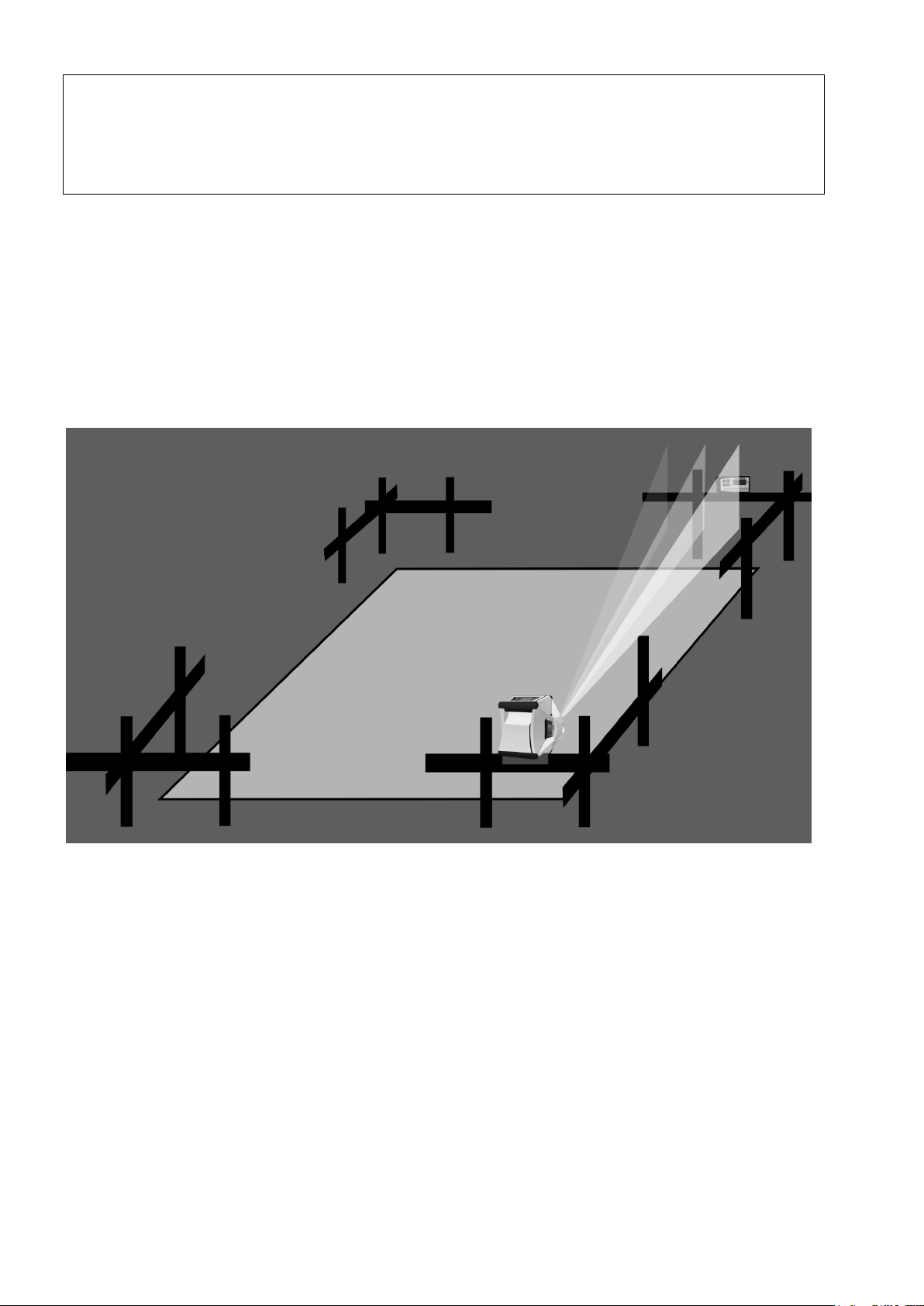
Alors l'inclinaison n'est plus ajustée pour aucun axe, mais juste
surveillée pour avoir éventuel un déplacement plus grand du laser
afin d’afficher.
Cf. également chapitre 4 pour les avertissements.
Tableau 3: Fonctionnement horizontal du système ALIGN sur les axes Y et X
Attention ! Si le laser quitte inopinément sa position,
l'ensemble de la mesure doit être répétée.
14.2 ALIGN - Vertical (Alignement)
14.2.1 Installation / Exécution
Figure 2: Fonctionnement vertical du système ALIGN
Le système laser Vision 2N ALIGN et le récepteur TE 90 ALIGN
peuvent également être utilisés à la verticale pour l'alignement.
Pour cela, le laser est placé sur un trépied, au sol ou sur un chevalet, p.ex., comme décrit au chapitre 2. Un exemple d'utilisation au
moyen d'un chevalet est décrit dans la suite.
Placer le laser conformément à Figure 2 de manière à ce que le niveau vertical du laser soit aligné avec le clou en mode de nivellement.
Positionner le récepteur TE 90 ALIGN sur l'objectif souhaité.
Orienter le récepteur de manière à ce que le logo « TE 90 ALIGN »
soit lisible à la verticale. (L'orientation du récepteur peut également
être modifiée dans le menu du récepteur, page 91)
96
Page 97
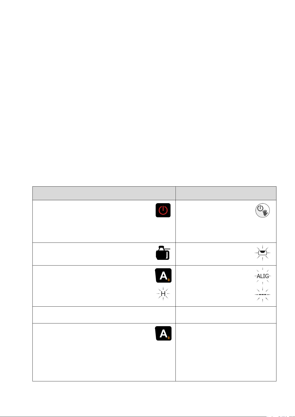
Remarque !
TE 90 ALIGN
VISION 2N ALIGN
Allumer le récepteur.
Orientation récepteur:
Écrit „TE 90 ALIGN“ Logo droit
lisible.
Allumer le laser.
Écran vers le haut.
Le symbole de l'appareil doit
être affiché.
Le laser procède
au nivellement.
Appuyer brièvement sur la
touche A.
Le système ALIGN démarre
pour l'axe X.
Le laser recherche
le récepteur.
Afficher
H
Récepteur trouvé
ALIG
– – –
Appuyer brièvement sur la
touche A :
Le système ALIGN est désactivé.
Le récepteur passe en mode de
fonctionnement standard et peut
être retiré.
La poursuite du récepteur
s'arrête.
Laser à la verticale en
mode de fonctionnement
standard.
(1) Placer le récepteur le plus loin possible du sol (min. 10 cm,
mieux 100 cm). Plus l'écart par rapport au sol est important,
plus la portée radio sera importante. Le récepteur doit se
trouver dans la zone de recherche du laser (+/- 9°).
(2) La vitesse de rotation et les zones de masquage peuvent
changer pendant la recherche du récepteur.
(3) Il ne peut y avoir aucun objet gênant entre le laser et le
récepteur ; dans le cas contraire, ceci peut influencer la
vitesse de recherche et rendre la localisation difficile.
(4) Si un second récepteur normal doit être utilisé dans le statut
du système ALIGN, p.ex., pour déterminer des points
intermédiaires, il faut ici veiller à ce que ce récepteur ne
recouvre pas le champ de réception du TE 90 ALIGN, mais
soit au-dessus ou en dessous de celui-ci. Ceci pourrait fausser
les résultats.
14.2.2 Utilisation / Affichage
Tableau 4: Fonctionnement vertical du système ALIGN
97
Page 98
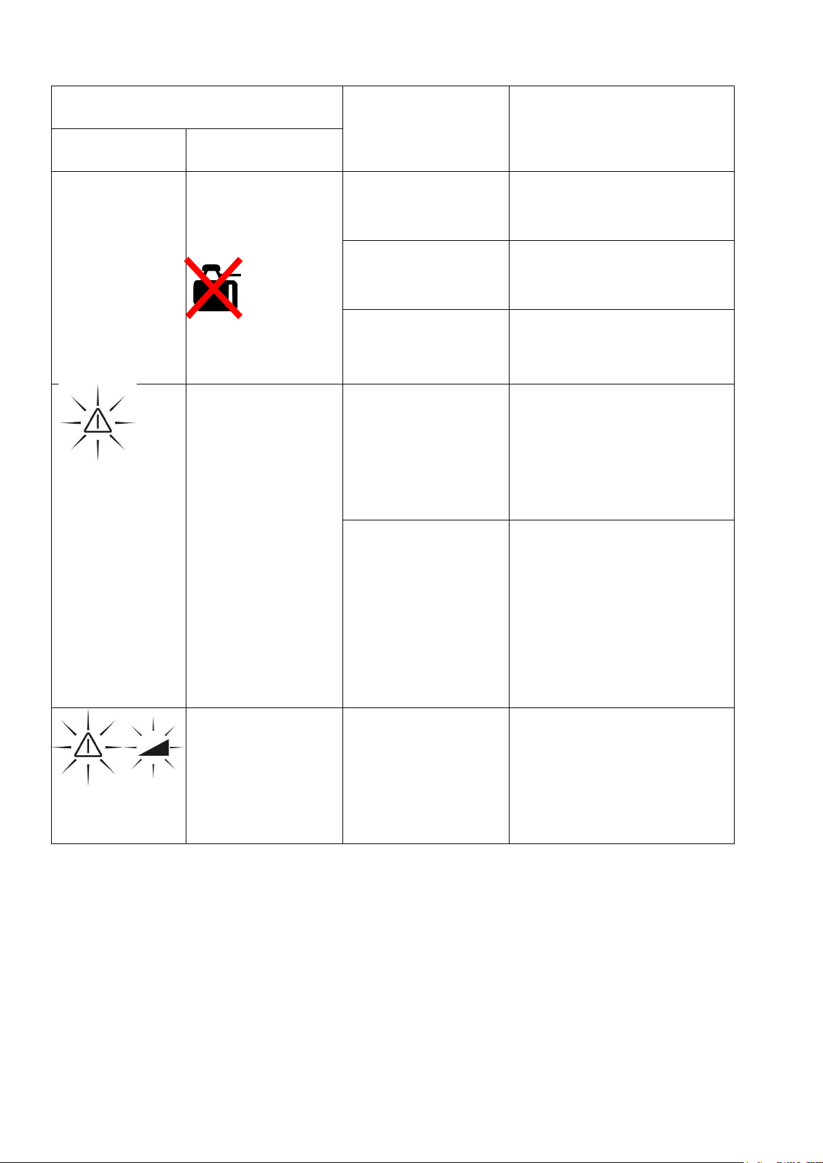
14.3 Affichage des pannes
Affichage
Erreur
Mesure
Laser
Récepteur
no Conn
A clignote
Le symbole
de l'appareil
disparaît
Pas de liaison
radio
Retirer l'objet entre le
laser et le récepteur
Récepteur
éteint
Démarrer le
récepteur
Portée
dépassée
Placer le récepteur
plus près du laser
ALIG FAIL
Arrêt du
rotor
Le rayon
laser clignote
Err
Mauvaise
orientation du
récepteur
Tourner le récepteur
ou modifier l'orientation du récepteur
dans le menu du récepteur, page 91
Plage de
recherche
max. de 15 %
dépassée
Horizontale :
inclinaison du sol
trop importante
Mesure impossible
Verticale :
mieux aligner le laser
Err
Le laser a reçu
un choc inopiné
Éteindre le laser et
vérifier l'alignement.
Redémarrer la
mesure
Tableau 5: Descripti
98
Page 99
15. L’accouplement du laser et récepteur
Allumer le laser
Maintenir enfoncé pendant 5 secondes
InFo
Indicateur INFO
Maintenir enfoncé pendant 3 secondes
ALIG
CHAn
Sélection du canal ALIGN
Select Choix du canal 0 – 35.
Commencer l'accouplement
ALIG
PAIr
L'affichage clignote, le laser attend TE 90 ALIGN
Settings TE90 ALIGN
Allumer le récepteur
Maintenir enfoncé pendant 3 secondes
Appuyer 2x
rdo
… apparaît dans le menu
Attention:
L‘accouplement vien implémentée en usine entre le laser et le
récepteur et doit être effectué par l'utilisateur seulement, si au
moins de deux systèmes ALIGN sont utilisés en parallèle et
que des interférences apparaître.
Dans ce cas, la fréquence du laser et du récepteur doit être réglée comme suit.
Calibrage du laser
99
Page 100
Sélectionnez un élément du menu
Appuyez jusqu'à l'élément du menu …
PAr
... apparaître
Sélectionner
Ok
Accouplement réussi
Accouplement complet
9500
XXXX
sur l‘affichage du laser le numéro de série TE 90
ALIGN
Éteindre le laser
Appuyer 3x: éteindre le récepteur
Maintenant, le laser et le récepteur sont couplés à la fréquence
choisie.
100
 Loading...