

Page 1
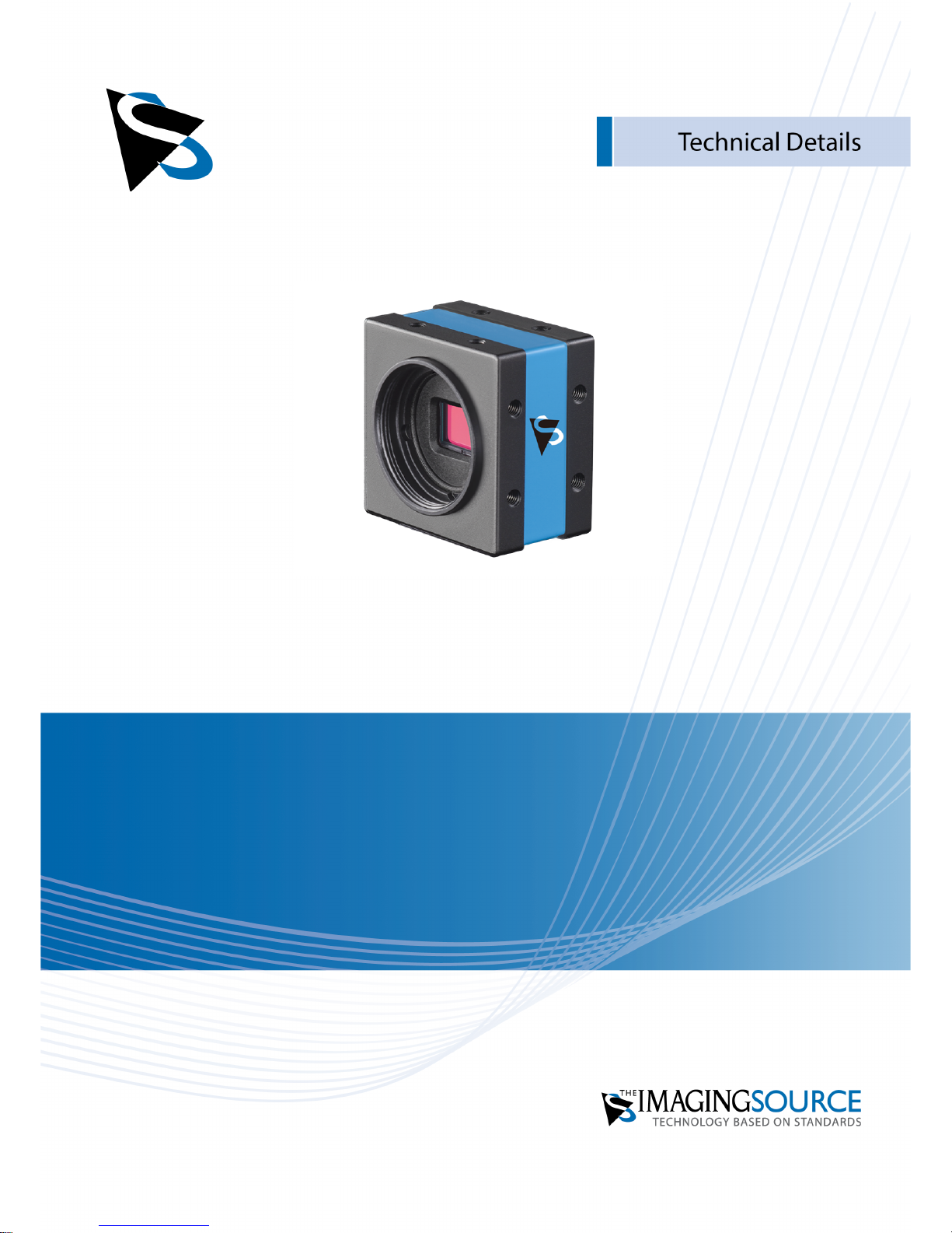
DMK 42BUC03
Technical Reference Manual
Page 2

DMK 42BUC03 Technical Reference Manual
2
Table of Contents
1. Quick Facts 3
2. Dimensional Diagrams 5
2.1 DMK 42BUC03 CS-Mount with Tripod Adapter ........................................................... 5
3. I/O Connector 6
3.1 4-pin I/O Connector ....................................................................................................... 6
TRIGGER_IN ............................................................................................................. 63.1.1
STROBE_OUT ........................................................................................................... 63.1.2
4. Spectral Characteristics 8
4.1 Spectral Sensitivity - MT9M021 .................................................................................... 8
5. Camera Controls 9
5.1 Sensor Readout Control ................................................................................................ 9
Pixel Format ............................................................................................................. 95.1.1
8-Bit Monochrome ................................................................................................................................... 95.1.1.1
Frame Rate ............................................................................................................... 95.1.2
Partial Scan Offset ................................................................................................. 105.1.3
5.2 Image Sensor Control .................................................................................................. 11
Exposure Time ....................................................................................................... 115.2.1
Gain ........................................................................................................................ 115.2.2
5.3 Trigger ........................................................................................................................... 12
Trigger Mode ......................................................................................................... 125.3.1
Software Trigger .................................................................................................... 125.3.2
5.4 Digital I/O ..................................................................................................................... 12
General Purpose Input ........................................................................................... 125.4.1
General Purpose Output ........................................................................................ 135.4.2
5.5 Strobe ........................................................................................................................... 13
Strobe Enable ......................................................................................................... 135.5.1
Strobe Polarity ........................................................................................................ 145.5.2
6. Revision History 15
Page 3
DMK 42BUC03 Technical Reference Manual
3
Quick Facts
1 Quick Facts
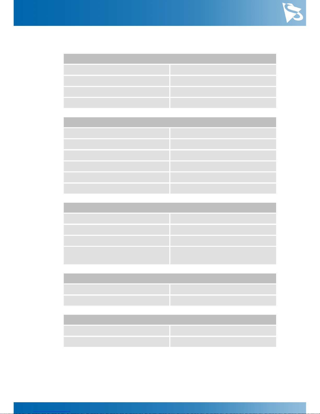
General
Dynamic Range
8 bit
Resolution
1280x960
Frame Rate at Full Resolution
76
Pixel Formats
8-Bit Monochrome
Optical Interface
IR-Cut filter
No
Sensor Type
Aptina MT9M021
Shutter Type
Global
Sensor Format
1/3 inch
Pixel Size
3.75 µm
Lens Mount
C/CS
Electrical Interface
Interface
USB 2.0
Supply voltage
4.75 VDC to 5.25 VDC
Current consumption
approx 250 mA @ 5 VDC
I/O Connector
4-pin connector for trigger and strobe or
general purpose input/output
Mechanical Data
Dimensions
H: 36 mm, W: 36 mm, L: 25 mm
Mass
70 g
Adjustments
Shutter
100 µs to 30 s
Gain
34 to 255
Page 4

DMK 42BUC03 Technical Reference Manual
4
Quick Facts
Environmental
Temperature (operating)
-5 °C to 45 °C
Temperature (storage)
-20 °C to 60 °C
Humidity (operating)
20 % to 80 % (non-condensing)
Humidity (storage)
20 % to 95 % (non-condensing)
Page 5
DMK 42BUC03 Technical Reference Manual
5
Dimensional Diagrams
2 Dimensional Diagrams
2.1
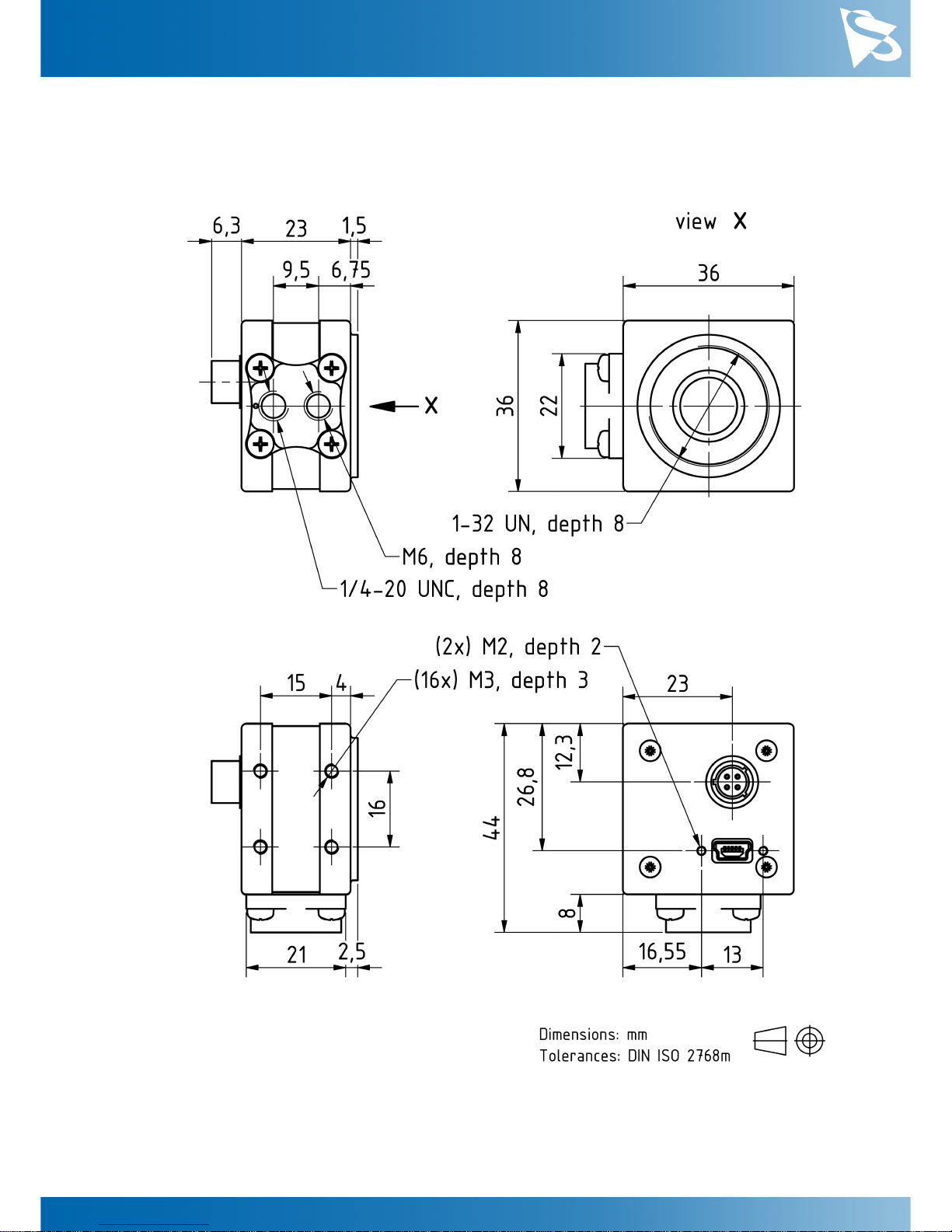
DMK 42BUC03 CS-Mount with Tripod Adapter
Page 6

DMK 42BUC03 Technical Reference Manual
6
I/O Connector
3 I/O Connector
3.1
4-pin I/O Connector
Rear view of camera
Pin
Signal
I/O
Remarks
Characteristics
Min
Typ
Max
Unit
1
GND_I/O
G3External Ground
----2
STROBE_OUT
O3Open drain
--24.01V3TRIGGER_IN (-)
I3Optocoupler ground
----4
TRIGGER_IN (+)
I3Optocoupler signal
3.32-
24.02V
1
max. 0.2A (ID) for open drain MOSFET!
2
min. 3.5 mA driver strength required!
3
G: Ground O: Output I: Input
The part number of this Hirose connector is HR10A-7R-4P. To create an I/O cable you
need a Hirose connector HR10A-7P-4S.
3.1.1
TRIGGER_IN
The TRIGGER_IN line can be used to synchronize the start of the exposure time with
external events. The Trigger section describes in detail how the image sensor's behavior
can be controlled.
The current input signal can also be read directly through the General Purpose Input
feature.
3.1.2
STROBE_OUT
The STROBE_OUT line's main usage is to indicate the integration time of the image
sensor which allows flashes, strobes or other light sources to be synchronized with
camera operation. The line's behavior can be controlled through the Strobe controls.
Page 7

DMK 42BUC03 Technical Reference Manual
7
I/O Connector
The output signal can also be directly controlled through the General Purpose Output
feature.
Page 8
DMK 42BUC03 Technical Reference Manual
8
Spectral Characteristics
4 Spectral Characteristics
4.1
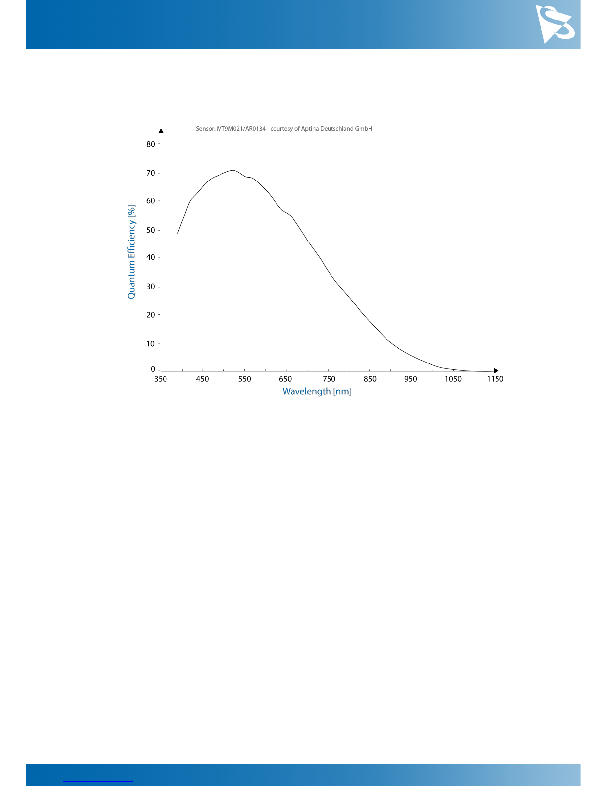
Spectral Sensitivity - MT9M021
Page 9

DMK 42BUC03 Technical Reference Manual
9
Camera Controls
5 Camera Controls
This section describes the parameters available for the DMK 42BUC03 camera.
The actual name of the parameter depends on the driver technology used to access the
camera. Parameter names are listed for the most common ways to access the cameras:
·
UVC/V4L2 (on Linux, via uvcvideo)
·
IC Imaging Control (on Windows, via Device Driver for USB Cameras)
5.1
Sensor Readout Control
5.1.1
Pixel Format
The pixel format defines the data type of the pixels transmitted to the computer. The
bits per pixel needed for a particular pixel format influence the required bandwith.
The way the pixel format is controlled varies significantly among the driver technology
used to access the camera:
·
When using the uvcvideo driver on Linux, the pixel format is defied by video4linux2.
·
When using IC Imaging Control, the pixel format is part of the video format - a
parameter which combines pixel format, resolution and readout mode. For more
information, refer to the IC Imaging Control documentation sections on
VideoFormat and VideoFormatDesc.
The DMK 42BUC03 monochrome camera supports multiple pixel formats with variable
bits-per-pixel settings. The names of the pixel formats and the way to select them
depends on the driver used to control the camera. The following table contains a short
overview of all possible formats followed by a more detailed description.
Pixel Format
Bits Per Pixel
UVC
TIS UVC Driver
8-Bit Monochrome
8
Y800
Y800
5.1.1.1
8-Bit Monochrome
This format transmits data using one byte for each pixel.
UVC drivers see it with the FourCC Y800.
The Device Driver for USB Cameras offers this pixel format as the Y800 video format.
5.1.2
Frame Rate
The frame rate is specified in frames per second and determines the camera's operating
speed.
The way the frame rate is controlled depends greatly upon which driver technology is
used to access the camera:
·
When using uvcvideo on Linux, the frame rate is selected from a list of available
frame rates.
Page 10
DMK 42BUC03 Technical Reference Manual
10
Camera Controls
·
When using IC Imaging Control, the frame rate is selected from a list of available
frame rates through APIs such as Grabber::setFPS or
ICImagingControl.DeviceFrameRate.
The range of available frame rates depends upon other camera settings such as well,
pixel format, resolution and readout modes.
Parameter
Frame Rate
Minimum
Depending on Pixel Format, Resolution, and Readout
Mode
Maximum
Depending on Pixel Format, Resolution, and Readout
Mode
The following tables show the maximum frame rate for some combinations of pixel
format and resolution.
8-Bit Monochrome
Width
Height
Maximum Frame Rate
1280
96025640
480
48
5.1.3
Partial Scan Offset
If the selected resolution is smaller than the sensor size, the part of the sensor that is
actually read out can be specified by the Partial Scan Offset X and Partial Scan Offset Y
parameters. By default, the camera automatically positions the offsets so that the center
of the sensor is used.
Parameter
Partial Scan Offset X
Minimum
0
Maximum
1280
Video4Linux2
X Offset
VCD Property
VCDID_PartialScanOffset
\VCDElement_PartialScanOffsetX
Page 11
DMK 42BUC03 Technical Reference Manual
11
Camera Controls
Parameter
Partial Scan Offset Y
Minimum
0
Maximum
960
Video4Linux2
Y Offset
VCD Property
VCDID_PartialScanOffset
\VCDElement_PartialScanOffsetY
5.2
Image Sensor Control
5.2.1
Exposure Time
The Exposure Time parameter defines the time the camera opens its (electronic) shutter
when it is taking an image.
Parameter
Exposure Time
Minimum
100 µs
Maximum
30 s
Default
auto
Video4Linux2
Exposure (Absolute)
The V4L2 Exposure (Absolute) control is using
100µs units
VCD Property
VCDID_Exposure\VCDElement_Value
5.2.2
Gain
The Gain parameter defines the amplification that is applied to the image at sensor
level.
Parameter
Gain
Minimum
34
Maximum
255
Default
auto
Video4Linux2
Gain
VCD Property
VCDID_Gain\VCDElement_Value
Page 12
DMK 42BUC03 Technical Reference Manual
12
Camera Controls
5.3
Trigger
The trigger mode can be used to take images at very specific points in time which are
specified by an electrical signal connected to the TRIGGER_IN pin of the I/O connector
of the camera.
5.3.1
Trigger Mode
The Trigger Mode parameter enables the trigger mode.
Parameter
Trigger Mode
On
Enable Trigger Mode
True
Off
Disable Trigger Mode
False
Video4Linux2
Trigger Mode
VCD Property
VCDID_Trigger\VCDElement_Value
5.3.2
Software Trigger
The Software Trigger function can be used to simulate a trigger pulse, in turn causing
one image to be exposed and delivered to the host computer.
Parameter
Software Trigger
Execute
Simulate one trigger pulse
Video4Linux2
Software Trigger
VCD Property
VCDID_Trigger\VCDElement_SoftwareTrigger
5.4
Digital I/O
The One4All series has one digital input and one digital output. The digital input can be
used as a Trigger input but the current status can also examined directly.
The digital output can be configured as a Strobe output to signal the exact moment
when the image sensor is sensitive to light so that external light sources can be
synchronized to its operation cycle.
5.4.1
General Purpose Input
The General Purpose Input parameter allows the current status of the TRIGGER_IN pin.
Page 13
DMK 42BUC03 Technical Reference Manual
13
Camera Controls
Parameter
General Purpose Input
True
TRIGGER_IN line status is low
1
False
TRIGGER_IN line status is high
0
Video4Linux2
ExtIO[1]
VCD Property
VCDID_GPIO\VCDElement_GPIORead
VCDID_GPIO\VCDElement_GPIOIn
5.4.2
General Purpose Output
The General Purpose Output parameter controls the status of the STROBE_OUT pin.
Parameter
General Purpose Output
True
Drive the STROBE_OUT line high
1
False
Drive the STROBE_OUT line low
0
Video4Linux2
ExtIO[0]
VCD Property
VCDID_GPIO\VCDElement_GPIOWrite
VCDID_GPIO\VCDElement_GPIOOut
5.5
Strobe
The strobe function controls the automatic generation of output pulses on the
STROBE_OUT pin which is synchronized to the image sensor's exposure time.
5.5.1
Strobe Enable
The Strobe Enable parameter enables the automatic generation of strobe pulses.
Parameter
Strobe Enable
On
Strobe enabled
True
Off
Strobe disabled
False
Video4Linux2
Strobe[0]
VCD Property
VCDID_Strobe\VCDElement_Value
Page 14
DMK 42BUC03 Technical Reference Manual
14
Camera Controls
5.5.2
Strobe Polarity
The Strobe Polarity parameter can be used to invert the strobe pulse output.
Parameter
Strobe Polarity
ActiveHigh
The STROBE_OUT pin is logically high during the
exposure time
True
ActiveLow
The STROBE_OUT pin is logically low during the
exposure time
False
Video4Linux2
Strobe[1]
VCD Property
VCDID_Strobe\VCDElement_StrobePolarity
Page 15

DMK 42BUC03 Technical Reference Manual
15
Revision History
6 Revision History
Date
Version
Description
2018/12/07
Initial release of this document
Page 16

DMK 42BUC03 Technical Reference Manual
16
DMK 42BUC03 Technical Reference Manual
All product and company na mes in this document may be tra demarks and tradena mes of their respective
owners and a re he reby acknowl edged.
The Ima ging Source Europe GmbH cannot and does not take any responsibility or liability for any information
contained in thi s document. The s ource code pres ente d in thi s document is exclusively us ed for di dactic
purposes . The Ima ging Source does not assume a ny kind of wa rranty expres sed or implied, resulting from the
us e of the conte nt of this docume nt or the s ource code .
The Ima ging Source Company res erves the right to ma ke cha nges i n specifica tions , function or design a t any
time a nd without prior notice.
Last upda te: De cember 2018
© 2018 The Ima ging Source
All rights reserved. Repri nt, also in parts, onl y all owed with permiss ion of The Imagi ng Source Europe GmbH.
All weights and di mens ions are a pproximate. Unl ess otherwi se spe cified, the lenses s hown in the context of
cameras a re not shipped wi th the se ca meras .
Headquarters:
The Imaging Source Europe GmbH
Überseetor 18, D-28217 Bremen, Germany
Phone: +49 421 33591-0
North & South America:
The Imaging Source, LLC
6926 Shannon Willow Rd, S 400, Charlotte, NC 28226, USA
Phone: +1 704-370-0110
Asia Pacific:
The Imaging Source Asia Co., Ltd.
2F., No.8, Xinhu 1st Road
Taipei City 114, Neihu District, Taiwan
Phone: +886 2-2792-3153
www.theimagingsource.com
 Loading...