

Page 1
INTEGRATED GUIDERINGM
22/36T, 24/38T INTEGRATED SHIFTRING
GUIDERING OR SHIFTRING WITH 104 BCD SPIDER
FINGER TIGHT
5 6 7 8
8a
8b
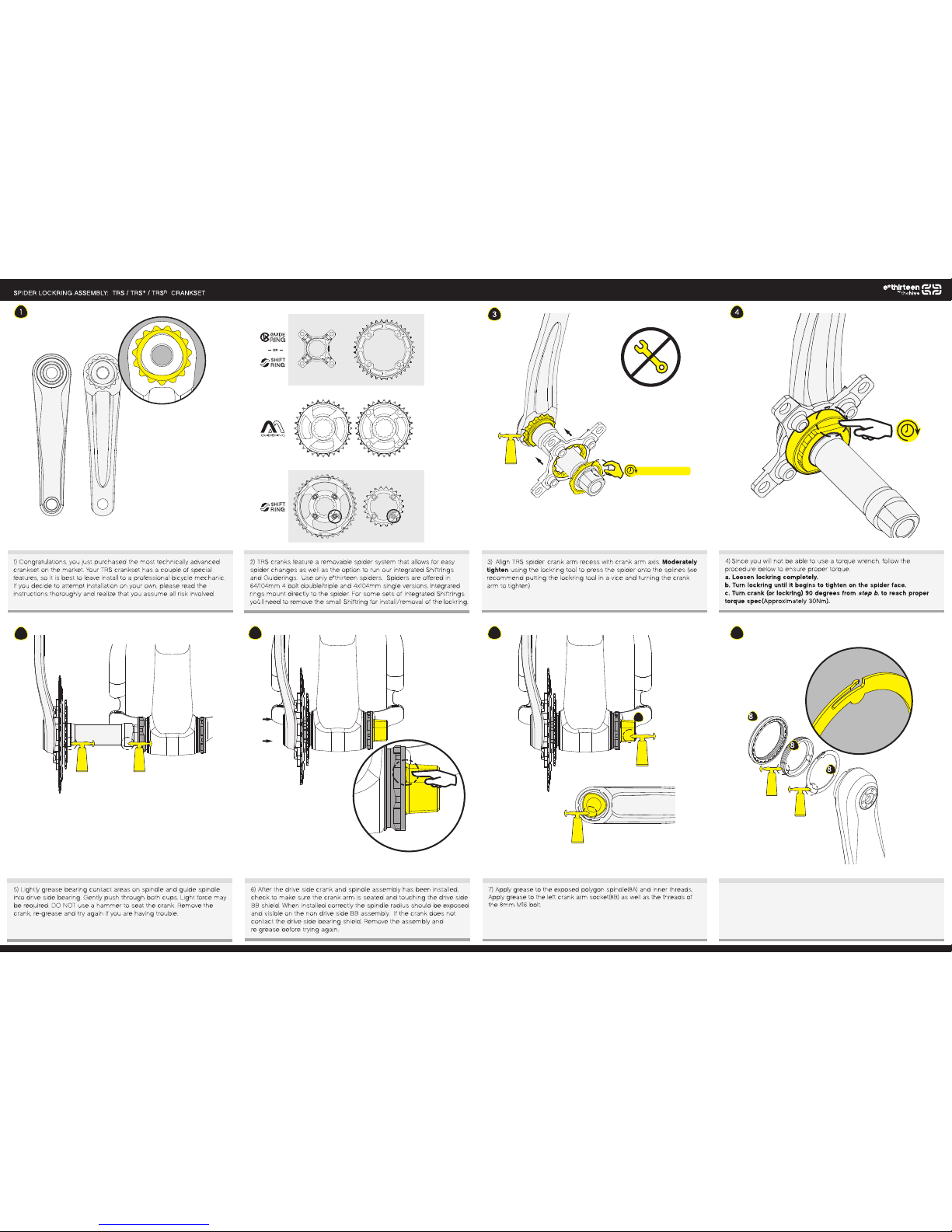
8) Apply light grease to the APS metal washer(8b) and threaded surfaces
of the plastic APS adju ster(8c& 8d). Install APS adjuster onto no n-drive
arm spring first, ensuring that the tang is outward. Next, sli p the threaded
portion of the adju ster over the arm and thread together.
b
c
d
Page 2
TRS/TRS+/TRSR Crankset Manual
REV. B 8 /2014
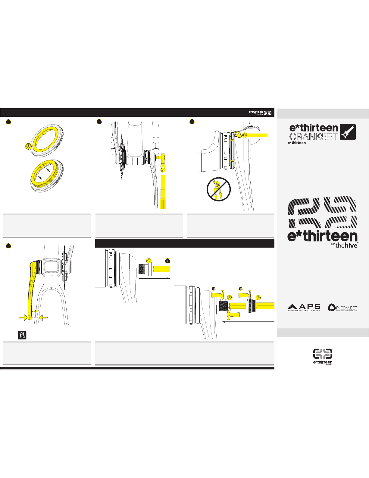
9) Note that when the adjuster is turned the center section moves in
and out, this preloads the bottom bracket bearings. Befo re installing
the non-drive arm e nsure that the APS adjuster is turn ed such that it
is in its flatt est position.
10) Using a torque wrench, install a nd tighten the non-drive crank ar m
assembly. Tighten the 8mm M16 crank bolt to 40-48Nm.
40-48Nm
9 10
11
12
12) Check for spindl e play and proper pre-load by squeezi ng non-drive
arm against the cha instay. Continue to turn APS until play is removed. If
APS adjuster is at its extreme and there is still play th is is an indication
that the bottom brac ket may be installed incorrectly or the fram e may be
out of spec. Install pedals to 31-34Nm.
Watch the v ideo // YOUTUBE.COM/B YTHEHIV E
ADAP
CRANK REMOVAL:
PRELOAD ADJUSTER (APS): TRS / TRS+ / TRSR CRANKSET
11) The APS adjuster should only be adjusted by hand. Never use pliers
or any other tool on the A PS adjuster as this can damage it Turn the .
FINGER TIGHT
Adjuster counter clockwise to increase preload on the bottom bracket
bearings. If you are unable to turn the adjuster at all, this is an indication
that the bottom bracket may be installed incorrectly or the frame may
be out of spec.
1) Remove crank bolt and washer.
1a) Grease & install crank removal plug with an 8mm hex fully into spindle. Grease outer face of plug as well, as it will contact extractor cap.
1b) Grease & install extractor cap into crankarm, torque to 6Nm with 10mm hex.
2) Turn removal plug counter-clockwise with 8mm hex. Removal plug will contact extractor cap and pull crank arm off spindle.
DO NOT ATTEMPT TO REMOVE CRANKS WITHOUT TIGHTENING THE EXTRACTOR CAP TO 6Nm.
All technical documents are located at www.bythehive.com/support
The Hive Europe
Klosterstrasse 6
83278 Traunstein, Germany
www.bythehive.com
+49 861 211 77 145
The Hive USA
405 East D Street suite C
Petaluma, CA 94952, USA
www.bythehive.com
+1 800 801 9936
 Loading...