

The Gramophone Company 541, 540, 661 Service Manual
“His Master’s Voice”
SERVICE MANUAL
fo r
F IVE - V ALV E
D UA L-WAVE A. C. RECEIVER
Model 66 I
A ND
DU AL- WAVE A. C. RADIOGRAMS
Models 5 40 and 541
(3) Rotate tuning knob until pointer is over 13.9
metres on dial and adjust S.W. oscillator trim m er
until maximum output is obtained with pointer
exactly on the 13.9 metre mark. Two settings
will be found at which this trim m er w ill peak;
care must be taken that the setting finally
selected is that which gives the lower capacity,
i.e., plunger furth er out. Failure to select the
correct position of the two w ill cause serious
tracking errors and loss of sensitivity.
(4) Tune receiver and signal generator to 15 metres
(20 me.).
(5) Adjust S.W. aerial trim m er for maximum output
while “ rocking” the ganged condenser slightly
to obtain the true resonant point.
(6) Retune receiver and signal generator to 13.9
metres, and note that signal is still tuned in
correctly on dial; if not, readjust S.W. oscillator
trimmer slightly until dial reads correctly and
then repeat tests 4 to 6 inclusive.
(7) Check foregoing adjustments carefully to ensure
that correct settings have been obtained on all
trimmers. Dial should now read correctly
throughout.
Supplementary Service Information fo r Radiogram Models 541 and 5 4 0
T E CH N I CAL SP E CI F IC A T IO N
PI C K-UP A U T O B R A K E ( T yp e 324)
D.C . resistance, 7400 ohms. Standard friction type, see page II.
Impedance at 1 000 cycles, 19,000 ohms.
One of the pick-up leads, and also the screening
over the leads, is to be connected to the black pick
up socket on the chassis. For service particulars
of this pick-up, see below.
D I S MA N T LIN G
RE M OV AL OF C HAS SI S
(1) Remove knobs.
(2) Disconnect loudspeaker plug, gramophone
m otor plug, and pick-up leads.
(3) Unscrew volume control escutcheon from side of
cabinet; withdraw sufficiently to allow insertion
of a screwdriver through hole provided in side
of escutcheon, loosen and remove control knob;
the escutcheon should now be detached and the
volume control pushed to the inside of the
cabinet.
(On Model 540, unscrew volume control
bracket from inside fron t of cabinet.)
(4) Remove two nuts from chassis fixing bolts behind
wooden chassis supports; the chassis is now free.
T H E P I CK- UP A N D M O TO R
To gain ac cess to the pick-up movement remove
the wax covering the tw o screw-heads in centre
(underside) of pick-up head and remove the screws.
The fo ur wax-covered screws fixing the pole pieces
of the pick-up must not be disturbed. These pole-
fixing screws are situated at either side of, and in
line with, the needle hole (Fig. I).
ADJUS TIN G T HE ARM ATU R E
The armature, which should be midway between
the tw o poles of the magnet, may be adjusted by
moving the clamp which holds the rubber damping
pad.
See that the slit in the rubber is locating the end
of the armature. When properly fitted, the flat end
of the armature w ill be just visible through the slit
in the rub b e r . Carefully remove all dust o r filings
in and arou n d the gap of the armature. A piece of
“ plasticine” will be found useful fo r this work.
TH E MAGNE T
Do not remove the magnet unless absolutely
necessary.
If it is necessary to remove the magnet, first
place a “ keeper,” consisting of a flat piece of iron,
across the poles of the magnet. When replacing,
the ground fac e of the magnet must be in contact
with th e poles.
RENEWAL OF C OILS
Be careful to connect and position the coils
correctly (se e Fig. I) when renewing. These coils
should be firm ly held in position w ith beeswax.
TH E M O T O R
To remove the motor on the radiogram: First
disconnect leads, then remove the three fixing screws
from the top of the motor-board (underneath tu rn
table), taking care not to lose rubber washers
between motor and board.
LU BR I C AT IO N
It is important that only good quality light
machine oil and grease, free from acid, should be
used for lubrication. It is advisable to lubricate
the motor regularly on certain dates, depending on
how much it is used; the oiling diagram w ill be found
inside the cabinet.
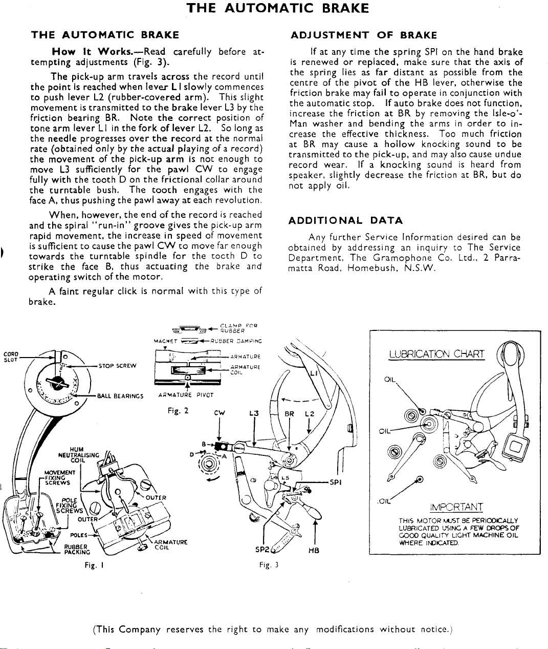
T H E AU T OMAT I C B RA K E
TH E A U T O M A T I C BRAKE
H ow It Wor k s. — Read carefully before at
tem pting adjustments (Fig. 3).
The pick-up arm travels across the record until
the point is reached when lever LI slowly commences
to push lever L2 (rubber-covered arm). This slight
movement is transmitted to the brake lever L3 by the
friction bearing BR. Note the corre ct position of
tone arm lever LI in the fork of lever L2. So long as
the needle progresses over the record at the normal
rate (obtained only by the actual playing of a reco rd)
the movement of the pick-up arm is not enough to
move L3 sufficiently for the pawl CW to engage
fully with the tooth D on the frictional collar around
the turntable bush. The too th engages with the
face A, thus pushing the pawl away at each revolution.
When, however, the end o f the record is reached
and the spiral “ run-in” groove gives the pick-up arm
rapid movement, the increase in speed of movement
is sufficient to cause the pawl C W to move far enough
towards the turntable spindle fo r the tocth D to
strike the face B, thus actuating the brake and
operating switch of the m otor.
A faint regular click is norm al w ith this type of
brake.
^ ^ U Bo E P
AD JU STM EN T O F B R AKE
If at any time the spring SPI on the hand brake
is renewed or replaced, make sure that the axis of
the spring lies as far distant as possible from the
centre of the pivot o f the HB lever, otherwise the
friction brake may fail to operate in conjunction with
the automatic stop. If auto brake does not function,
increase the friction at BR by removing the lsle-o’-
Man washer and bending the arms in order to in
crease the effective thickness. Too much friction
at BR may cause a hollow knocking sound to be
transmitted to the pick-up, and may also cause undue
record wear. If a knocking sound is heard from
speaker, slightly decrease the friction at BR, but do
not apply oil.
A D D IT IO N A L D A T A
Any further Service Information desired c an be
obtained by addressing an inquiry to The Service
Department, The Gramophone Co. Ltd., 2 Parra
matta Road, Homebush, N.S.W.
THIS MOTOR MUS T BE PERIODICALLY
LUBRICATED USING A FEW DROPS OF
GOOD QUALITY LIGHT MACHINE OIL
WHERE INDIC ATED.
(This Company reserves the right to make any modifications w ithout notice.)
TECHNICAL SP E CIF I CATIO N
V O L TA G E RANG E
20 0 to 2 60 v olts, 40 to 60 cycl es .
It is i m portant t hat the r ece i ver be ope ra te d at
th e c or re ct vo l tage ; t he voltag e ta ps on the mains
tr ansfo rme r s h ould be util i zed as foll ows;
Voltage of A .C. S u p ply Use Tap Designa t ed
2 0 0 - 2 2 0 volt s 2 0 0
2 21- 240 „ 240
2 41- 260 „ 260
C O N S U M P TIO N Rad io G r am.
Mo d el 661 . . ..73 w at ts —
„ 541 and 540 .. 7 3 „ 90 watt s
W AV E-LE NGTH RANGE
13.9 me tre s ( 21.57 m e g a c ycles ) to 4 7 metr e s
(6 . 38 m e g a c y c le s ).
187 met res (160 0 k c.) t o 54 5 metre s (5 50 kc.).
MA X. U ND I S TO RT E D POWE R O U T P U T
4.5 w atts.
DIM EN SIO NS Height W i d th D ep t h
Mo d el 661 . .
„ 541 ..
3 5f"
3 I f '
W E IG H T N e tt
Model 661
541
30J "
35"
62 lbs. 73 lbs.
91 „
Ι 3 Γ
I7§”
Gros s
108 „
L OU DSPEAKER
Mo d e l s 661 and 541 use a 12" sp ea ke r, and
Model 540 a 10" spe ake r , the f i e l d windi ng a c t i n g as
fi lter chok e .
D.C. res istance of field c oil, cold 18 00 ohms.
voice ,, 2
400 cycle i mpe dan ce of vo i ce coil 2. 35
VAL VE S
Mod els 661 and 541 : 6 K7GT, 6 J8 G, 6 B8 G, 6 V 6 G ,
5Y3G .
Mo d el 54 0: 6 J8 G, 6U7G,~ 6B 8G , 6 V 6 G . 5Y3G.
CI R CUIT
The se Mo d els ar e S uperheterody ne R e c eiver s,
empl oyi ng fi ve va lv e s . The o sc i ll a t or cir cuit is a
littl e unusual, and is desig ne d to prov ide r ela tively
con s t a nt oscillatio n a mpli t ud e ove r the very wide
tu n i ng range emplo yed in both wave ba n d s . T h e
wave -ba nd s w it ch i ng has been s im plified in Mod els
661 and 541 by the e limina t ion of switchi ng in the
primary cir cuit of the a e r i a l transf o rm er. T h e
freq ue nc y c h an g er is f oll owed by a si ngl e stage I.F.
amplifi er, using a 6K 7G T va lv e in Models 6 6 1 and 541,
operat i ng a t 457.6 kc. and f eed i ng i nto a 6 B8 G d uo-
dio-pen tode, who se diode s a r e used as demodulator
and A.V. C . rec tif ie r r espectiv ely . The p ent o de
sectio n of t his va l v e is resi sta nce -ca pacity-c ouple d to
a 6 V6 G out put valve. In M ode l 5 40, t h e I.F. amp l i fie r
is a 6U7G valve, operating a t 460 kc.
The broadc as t b a n d ae r i al coupling is
throug h a Litz-w ound iron-core c oil of e xcept i onally
high eff icien c y . A ll I.F. transformer s also employ
Litz-wou nd ir on-core coils and silver- coated titan ium
d i oxide fi x ed con d ense r s — tunin g bei ng acco m p lished
by axi a l a djustm ent o f the iron c o r e s . Indu ctive
pa ddin g of th e oscill a tor circu it is used on bot h w a ve
bands, thr ou gh th e me dium of adju stabl e iron core s;
special close toler ance fi xe d padd i ng con de n s er s are
used.
Model s 661 and 541 inco rpo rate the “ His
Master ’ s Voice” A utomat ic Exp anding Se l ector,
whic h comp r i s e s a special f orm o f I.F. am plif ier, w h ose
band widt h is di re ctl y cont rolle d by the s t ren gth
of the in c om i ng signal, pr ovidi ng br o ad tuning and
cons equent high f idelity o n powerfu l signals and
giv i ng p r ogr ess i v ely sha rper tun ing as signal streng t h
is r educed. Norma l 2-circuit i nput and output
tr ansformers a re used, b ut they are m ore cl os e ly
co upled than usual, t h u s giving a b road, f l at-t opped
res onan ce curv e o f low selec tivity , p ermi tti ng faith
ful transmis s i on of side b a n ds up t o a bout 5, 000
cyc l es/s e c. Feed-ba c k is t aken t hrough the co n
dens er C N fro m th e un-by-pas s ed I.F. cat h ode r esis t or
to the p l a t e of t he c o nverter valve ; this f e ed-back is
so ad juste d t hat whe n the I.F. valve is opera t i ng at
full sensiti vity, the c ou pling betwee n t he first I.F.
p rimary and secon dary is el ectrically loosened suffi
ci en t l y to provi de a res onanc e c urve , having a sin gle
sha rp peak and giv in g very h igh se l ec t i vit y. Ho wev er,
as th e bias on the I.F. v alv e is inc r e a s e d by A.V.C .
act i on on st ron g signals, its mu tu al co n ducta n c e is
re duced , all owi ng the fi r st I .F . tra nsf ormer t o ret ur n
to its nor mal br oad l y tu ned co nd ition. The con
denser C N is pr e c i s e ly adju sted a t the fa ctory and
seale d , and its ad justmen t shoul d und er no cir
cumsta nc es be i nterfere d with .
A.V .C. volt age is appli ed to the conve rte r and
I.F. valv es on b oth wave-band s; the ma ximu m contr ol
vo l tag e deriv ed from the A .V .C . dio de , wh ic h is fed
fr om the I.F. plate , is a pp l i ed to t he convert er, bu t
the I.F. val ve is cont ro l led by the r e c t i f ied signal
volta ge f rom the signal diode; this vol ta g e sim ul
taneously serving the purpose o f A. V.C. volt a ge, is
also applied to the 6 B8 G audio fre qu ency valve. In
Model 540, bo t h stages deriv e A .V.C. fr om the
A.V .C. diode.
Inv e rse feed -ba ck is a pplied to th e co mp l ete
au dio fr equency system th rough the Tone Mon itor
Control, from th e secondar y of th e o utpu t tra ns
fo rm e r to a tap on the Volum e Contr o l; in this w a y
the whole of th e A. F . circ uit s benefit fro m t he dis
tortion-red ucing prope rti es of such f e e d - b a ck. In
add i tio n, t he cir c uits a s s ociat e d w i th the Tone
Monitor Swit ch provi de var ying d e g re e s of feed
back differing wit h freq uency, thus en s u r ing con trol
of to nal balance . Furthermore, the deg r e e of f eed
back va r ie s wi th t he setting of the V olum e Co nt ro l
in such a way as to automatical l y prov ide the best
type of respon s e for b oth lo c a l and di stan t r eceptio n
and a t all v olume level s. T he sp eake r field win ding
is used as a fi lter c hoke, in conj un ction wi th t w o
16 mfd. w et elec trolyti c co nden sers, on e of which
is of the re g ula t i ng t ype. It is essentia l tha t the
positio ns of th e s e condensers in the ci r cu i t shall
no t be inte rchanged. The co ndens ers ar e mount ed
2
 Loading...