

The Gramophone Company 409, 429 Service Manual
PR IV AT E A N D CO N F ID E N TI A L
“His Master’s Voice”
SERVICE MANUAL
FO R TR A D E USE O N L Y
for
SIX VALV E
D UAL WAVE A.C. RECEIVER
M ODEL 409
AN D
DU AL WAVE A.C. RADIOGR AM
M OD EL 429
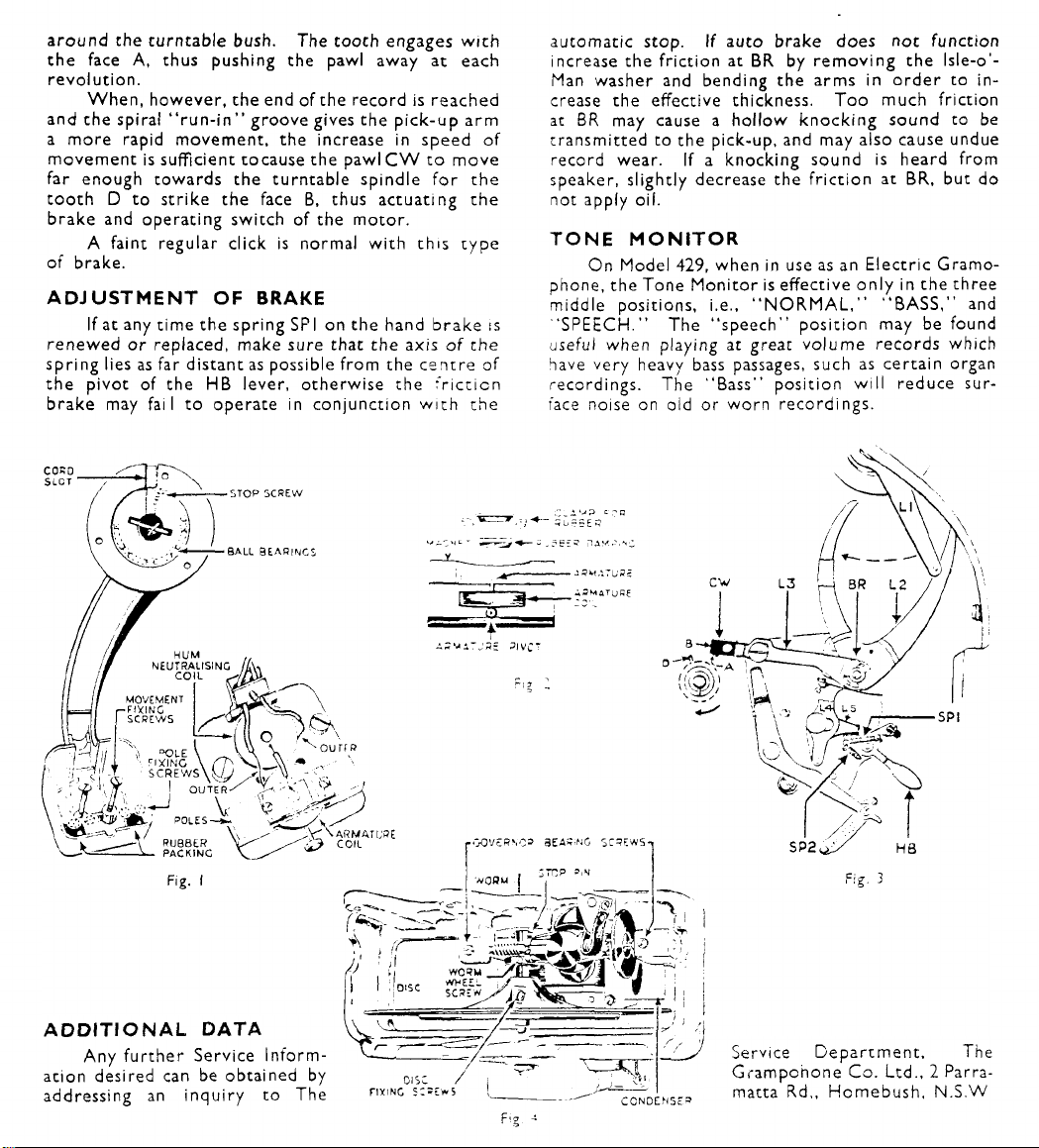
aro un d rhe tu rn ta ble bush. The tooch engages w it h
the face A, thus pushing the pawl away at each
revo luti on .
W h en , ho we ve r, the end of the re cord is re ac he d
and th e spiral “ r un- in” gro ove gives the pick-up arm
a mo re rapid mo vem e nt, the increase in speed of
mo ve m en t is sufficient tocause the pawl C W to m ov e
far enough t ow a rds the tu rn tab le spindle for the
too t h D to strike the face B, thus actua ting the
brake and oper ating sw itch of the motor.
A faint regular click is normal wit h this ty p e
of brake.
A D J U S T M E N T OF BRAKE
If at any time th e spring SP I on the hand b ra ke is
ren e w e d o r replaced, make sure that the axis o f the
spring lies as far distant as possible from the c e n tr e of
the pivot of the H B lever , otherw is e the f ri c ti on
bra ke may fail to o pe rate in conj unctio n wi t h the
autom atic stop. If auto br ake does no t function
increase the fr iction at BR by re m o v in g the lsle-o'-
Man was her and bending the a rms in or d e r to in
crease the effective thickness. To o much friction
at B R may cause a h ol low k no ck in g sound to be
transm itte d to th e pick-up, and may also cause undue
record wear. If a knocking sound is heard from
speaker, slightly decrease the fr ict ion at B R , but do
not apply oil.
T O N E M O N I T O R
On Model 429, w hen in use as an Ele c t r ic G ra m o
phone, the To ne Mo n it o r is effecti ve o n ly in the th ree
middle positions, i.e., “ NO RM AL,” “ B A SS , ” and
'SP EECH. ” The “ s pee ch” posit ion may be found
useful when playing at great vo lu m e rec ord s which
have ve ry heavy bass passages, such as ce rta in organ
recordings. Th e “ Bass” position w i ll re duce sur
face noise on old or wor n re cord ings.
A D D IT I O N A L D A T A
An y fu r th e r Se rv ic e In for m
ation desired can be obtained by
addressing an i nq uir y to The
OISC /
fixing s:=iws
CCNDtHSc=>
Service D ep a r t m e n t,
Gra m p oh o n e C o. Ltd.,
matta Rd,, H om e bu s h.
The
2 Parra-
N . S . W

T ECHNI CAL SPE C I F ICAT I O N
V O L T A G E R A N G E
200 co 250 volts, 40 to 60 cycles.
It is im p o rta n t th at th e rec ei ve r be op erate d
at the cor re ct volta ge; the v ol ta g e taps on the mains
tran sf or me r should be utilized as follow s:
Voltage of A .C . Supp ly. U se Tap Designated.
200-220 volts 200
221-240 „ 240
241-260 „ 260
C O N S U M P T I O N
Model 409
Model 429
Radio
96 w atts
96 „
Gram .
70 watts
W A V E - L E N G T H R A N G E
13.9 metres (21.57 m egac ycle s) to 47 metres
(6.38 megacycles).
187 me tres (1600 kc.) t o 545 metres 1550 kc.).
M A X . U N D I S T O R T E D P O W E R O U T P U T
7 watts.
D I M E N S I O N S
Model 409
Model 429
He ig h t
35!"
34"
Wid tn
30! 1
34 '
Depth
13?"
Ι 9 Γ
W E I G H T
Model 409
Model 429
Net:
76 ibs.
I 1 ς
Gross
93 lbs.
224 ,,
L O U D S P E A K E R
Model 409 uses a 10" speaker, anc ivlodel 429 a
12" speaker, the field windin g acting as niter choke.
D.C . resistance of field coil, cold 1200 ohms.
D.C . resistance of v oic e coil . . 2 ,,
400 cycle impedance of voic e coii 2.35
VA L VE S
6J8G , 6 U 7 G , 6 H6 G, 6B8G. 6L6G. 5 W G .
C I R C U I T
These models are s upe rhe tero dyne s inco rpora t
ing a fairly co nve nt ion al frequency-changing circuit
using a 6 J8G triode -h ep to de co nve rte r .-alve. The
oscill ato r circuit is designed co provide relatively
constant oscillation amplitud e o ve r the /ery wide
tuning range in co rp or a te d in the shcrt-^ave band.
The fre que ncy ch ange r is fo llow ed by a s.ngle-stage
I.F. ampl ifier using a 6U 7 G operating at 460 kc.,
and feeding into a 6H 6 G douDie-diode vaive. One
diode of this valve is used as demodulator, and the
remain ing diode f uncti ons in cne "St ati c L im i te r”
circuit. The d e m o d u la te d signal passes throug h the
volum e contr o l to a 6B 8G diode-pentode used as
A.F. am plifier , wh ic h is resistance-capacity coupled
to a 6L6 G beam-typ e ou tp ut valve. One diode of
the 6B 8G is uti lized t o provide A VC voltage, being
fed from the plate of the I.F. amplifier.
The b roa dc ast band aerial coupling is thr ough
a Litz-wound iro n co re coil of excepti onally high
efficiency. All I.F. tr ans form er s also emplo y Litz-
wou n d ir o n c o re coils and silver-coated tit anium
dioxide fixed co nd en se rs, tuning being accomplished
by axial adj us t m en t of the iron cores.
I.F. coupli ng b et w ee n freq uency changer and
I.F. valve is thr o u gh a three-circui t band-pass arrange
ment in the in te r es ts o f higher se lecti vity ; coupling
betwee n the first and second coils is magnetic and
betw ee n the se co nd and third coiis capacitive, the
third coil being conta in ed in a separate shield can.
Two degrees of se le ct iv ity are provided, under con
trol by the T o n e Mon it or , through the medium of
ter tia r y w ind ing s on the I.F. transformers, that on
the first tr a n s fo r mer being used to provide addi
tional coupling in the broad position, while the
second stage tert i a r y acts as a magnetic screen when
short-circuited, so loosening the coupling. The
third t ra n s fo rmer has an additional compensating
winding which . s switched into circuit when the
tert iar y is open.
Inductive pa ccin g of me oscillator circuit is used
on the broadcast oana; on tne sr,ort-wave band no
padding adjust ment is re qu ired. Special close to le r
ance fixed padding condensers are used.
A.V.C . voltage is apolied to the frequency-
changer. and I.F. amplifier on bctn wave-bands. A
fraction of the A .V .C . voltage is aiso applied to the
6B8G A.F. valve.
Inverse feea-oack is aopliec to the complete
A.F. system, tn rc ug n the Tone Mo nitor control,
from the se condary c f the output transformer to a
tap on the volu me con tro l; in this way the wh ole of
the A.F. circuits oenefit from the distortion-reducing
properties of suc.n feed-back. In addition, the cir
cuits associated w.th the Tone Monitor switch p ro
vide varying degrees of feed-back differing w ith fre
quency, thus pr ovidi ng control cf tonal balance.
Furthe rmore, the degree of feed-back varies w ith the
setting of the vo lum e control in such a way as to pro
vide the best resoonse for both local and distant r e
ception, and at ail volume levels. All valves are self-
biassed by catho de resistors. The speaker field
winding is used as a filter choke, n conjunction with
two 16 mfd. we t type electrolytic condensers, one
of which is of the regulating r/oc·. It is essential
that the positions of tnese conce-'sers m the circuit
shall not be interchanged condensers 3re
mounted on the speaker c-c thus protected
against damage ’ tne ;oea<er ; „g s withd rawn
while the r ec c- e ' s " coc-*a:c'
C I R C UI T S
The c ir c ui t diagrams of Models 409 and 429,
to g e th e r w it h all co mpone nt values, are show n on
pages 4 and 5.
W A V E - B A N D S W I T C H IN G
Thi s is car rie d out by means of a two-deck switch.
The os c il la to r pr im ar y coils are connected in series
and not sw it ch e d. Addi tional capacitive feed-back
is applie d across th e padding co nd en ser on the s ho rt
wav e band, and this is switched by contacts on the
wave-c hang e switch .
Th e first position of the sw itch ( ex tre m e ant i
clo c k w i s e ) con nec ts the short-w ave coils and asso
ciated co mp o ne nts , and the second position the
broadca st circuits, while in the third position the
pick-up s oc kets are connected in circuit, and the
radio circ ui ts disconnected.
T O N E M O N I T O R
This is a five-position two-deck switch. In
Model 409 t he following effects are secured in the
vario us s w itc h positions:
1st Pos ition iW i a e Range): Bass and treble
boost, and oroad tuning, for highest
fidelity.
2nd Positio n (N o r m a l ): Bass and treble boost,
and sharp tuning. For normal and dis
tant reception.
3rd P osit ion (Bassi: Bass boost ana treble cut.
wit h sharp tuning. For deeper tone,
and reduction of static and surface noise
4th Posit ion (Spe ech) : Bass cut and treble
boost, with sharp tuning. For long
distance reception of speecli with good
intelligibility, or reduced bass response
5th Position (Ov e rs e as ): Bass and tre ble cut,
with broad tuning. For easy sh ort- wave
tuning with reduced background noise
and freedom from microphony.
In Model 429, additional bass boost is pro vide d,
wh i c h is cut in by the Radio-Gram, switch in the
" G ra m ." position, and rem ov ed in the “ R adi o ”
positio n.
S T A T I C L IM IT ER
This device is contr olle d by a switch located on
cne right-hand side of the cabinet, in the case of
Mo d el 409, and on the con trol panel in Model 429.
It is int ended to limit the peak level of static or
elec tr ic al disturbances of peaky wave-form to a
value not greatly exceeding the level of the c a rr i er
of the station oeing received, thus pre ventin g the
dr o wni n g of the signal by very loud bursts of static,
it is useful crtiefly in long-distance receptio n of
speech, and in short-wave reception wher e e lectr ica l
..nterference is severe. It usually has a slightly
de tr im e n t al effect on the ton e of musical re cep tio n,
ana snould therefor e be switche d off when not re-
dui re d. It nas no effect on the sensitivi ty or
seiec civ ity cf the receiver.
E X T E N S I O N SPEA KER
= in-jacks are provided at the back of the chassis
■;r :n e co nnection of an extension speaker. They
a re -vired co the secondary of the outp ut tra n s
fo r m e r . ana are suitable for connection to any icud-
:oea.<er having a voice coil impedance be tw e en
2.5 and 4 cnms. An impedance of 3 ohms at 400
z.c'.ss is reco mmende d, and the speaker should pre-
'S'-aciy be of perma nent magnet type, and req uir es
-c transfo rm er. The “ His Master's V o ic e ” Exte n
d e r Speak-;·· s very suitable, and is fitted w i th a
consta nt ’'oed ance volume control. A switch,
-narked “ REC’R S PKR. ” is installed beside the jacks
co p e rm it c~o receiv er speaker to be silenced if
desired wne- an extension speaker is in use.
PR E L I M I N A R Y TESTS
1. Switc h on rec eiv er and note that dial lights up and
changes c ol ou r wnen wave-band switch is
ope ra te d.
2. If no signals can be cuned in, remo ve the shield
from th e 6B8 G valve and wit h the volume control
full on and earth wire disconnected, touch the
finge r co th e grid cap of the valve, when a loud
hum should be heard; a hum should also be heard
wi th wave-change switch ac “ G r a m. ” , wh en the
red pick-up jack is touched. This indicates that
the A.F. side of the recei ver is work ing, and the
faulc prob ab ly lies in the R.F. or I.F. circuits.
Sho uld no hum be heard ,a faulc exists be tween
first A.F . scage input and the speaker.
3. Ch e c k all valves for heater co nti nuit y and free
dom fr om internal snorts.
~o deter mine if cne fault lies in the lou dspeak er,
connec t a nigh impedance A.C. vol cme cer or
outp ut meter, range 0-3 volts approx. co che
O i ce coi: terminals of che speaker. S w it ch on
rec ei ve r turn volume control fully on, and tu ne
across cne oroadcast band when scacions are
kno w n co be transmiccing. If mecer does noc
deflect, cne fault lies in the rec eiver cir cuits or
r, the field circu it of the speaker. If th e m ece r
deflects out no sound is heard, the speaker voice
coil is at fault.
:f the fauit is still undiscovered, remove chassis
and speaker from cabinet anc compare voltages
wit h taoie ;i ven on page 6.
 Loading...