

The Gramophone Company 329, 359 Service Manual
PR IV AT E A N D C O N F I D E N T I A L
“His Master’s Voice
SERVICE MANUAL
FO R T RA D E USE O N L Y
I f
for
FI VE- VALVE VIBRA TOR
P OWE RED BA T TER Y RECEIVERS
Dual - Wave
B r oa dc as t
Model 329
Model 359
T ECHNICAL SP EC IF IC A TIO N
BATTERY
Th e battery required for the opera tio n of this
re c eiv e r is as foll ows:
On e 6-volt 150-amp. hour accumulato r.
Th e batt ery supplied wit h the re cei ver is a lre ad y
fully charged. This battery should be re-charged
at least once monthly, or a lte rn ati ve ly w h e n eve r
the specific gravi ty as measured with a hy dro met e r
falls b e l o w 1.140 or the voltage w ith the re c e i v e r
in oper a ti o n falls below 5.4 volts.
CO NS UM PT IO N
The battery consum ptio n of this model is
ap p r ox i m a t e ly 1.0 amp. in norm al op eration.
SPEECH O UTP UT
Ap p ro x im a t e ly 0.75 watts undlstorted.
WAVE-LENGTH RANGE
187.5-545 metres ( 1600-550kc.).
*13.9-47 metres ( 21.57-6.38mc.).
*Model 329 only.
DIME NSIONS
Height Widt h
35f 29.1"
Dep th
W EIGH T
Wit ho ut
Bat te r y
N et t .. 7 1 Ibs.
Gr o ss . . 82 lbs.
Wi t h
Ba tt e ry
136 lbs.
VALVES
IC7G Conv er te r.
I D 5 G 1st I.F.
IF 7 G 2nd I.F. and De mo du lat or.
I F7G 1st A F and AV C.
IG 5G Power.
LOUDSPEAKER
Th e loudspeaker used is of the pe rm a ne n t
ma gn e ti c type. It is a 10-inch model with a vo ice
coil imp edance at 400 cycles of 3.3 ohms.
CIRCUIT DESCRIPTION
This model embodies a 5-valve su p e rh e te ro dy n e
chassis comprising a Pentagri d con v er te r follow ed
by a two-stage I.F. am plifier. Dem od ula tio n is
effecte d in the diode circui t at the last I.F. va l ve ;
the demo du lated signal is then amplified by a duo-
diode -pent ode , one of the diodes of which supplies
the AVC voltage ; this valve is resistance-capacity
cou p le d to a pentode which functions as o u t p u t
stage.
Th e valve filaments are c onnected in a se ries-
parall el arr angement .
A split reed synchronous vi br a to r is used in the
vib r a t or po w e r supply circuit ; this ena bles the
ou tp u t valve t o be adequately biassed by means of
a resisto r in the negative high tension lea d; all
oth e r bias voltages are obtained from th e fila m en t
circuits.
Coupling to the aerial on the broa dcast band is
effected th rou gh an iron-cored tran s fo r m er having
the normal tu ned secondary.
The t hr ee I.F. transformer s are perm e a bi li ty
tuned and e mp loy Litz wo und coils w it h sliding
iron cores. T h e AVC voltage is applied to the con
ve r t e r and I.F. valves. No AVC voltage is applied
to the S . W . c o n ve r t er grid. O p ti m u m delay volt age
is provided f or the A VC diode by means of fi lam e nt
voltage drop so that adequate p o w e r o utp u t may
be obtained before the AVC system takes con t ro l.
Padding on the broadcast band is effected by
adjustmen t of the oscillato r secondary ind uc tan ce
by means of an adjustable iron core, in con ju nc ti on
with a fixed padding condenser.
On the S .W . band no padding a dj u st m e nt is
required. All R.F. tri m m er s are of the air di el e ct r ic
type, using a robust plunger type co ns t ru ct io n,
which is e nt ir ely im mune to change of cap ac ity or
detrim en tal atmos phe ric influence.
WAVE BAND SWITCHING (Model 329)
This is carried out by means of a tw o -p os itio n
switch. The osci llato r primary coils are c on n ec te d
in a series and are not swit che d; h o w e v e r , a little
feed-bac.< is applied across the padding c o nd e n se r
on the S. W . band, and this is switc hed in and out
by contacts on the wave-change switch.
The first position of the switch (an ti- cl oc kw is e)
connects the short- wave coils and ass ociate co m
ponents in cir cuit, w hilst the second pos itio n does
the same with the broadcast band co m po n en ts .
TO NE M ONITOR
This is a four-position, single-deck sw it c h , used
as a combined to ne c ontrol and bat te ry s w itc h .
1st P osit ion .— Rec ei ve r switche d off.
2nd Position (N o r mal ) .— Rec e i v e r on, max i
mum tre bl e and bass note rep ro d u c ti o n .
3rd Positio n (Bass).— Rece iv er on, high a u d io
frequ en cy cut in trod uced.
4tn Pos ition (Spee ch) .— Rec e iv e r on, low
audio-frequency cut intro du ce d.
DIAL LAMPS (6.3v. 0.15 amp.)
The dial lighting is controlle d by a push button
mounted on the side of the cabinet, w h ic h should
be pressed during the process of tumng-in stat ion.
Wh en released, this button will ex tingui sh t he dial
lighting, thus saving unnecessary drain on t he b at ter y.
2
VIBRATOR CIRCUIT DESCRIPTION
Th e c irc ui t o f the vib r a to r uni t used w ith this
model is indicated on pages4& 5. Th is unit includes the
vib r a t or itself, which is enclosed in a separate metal
con tai ne r arr anged so that it can be plugged into or
remo ve d fr om a socke t loca ted in the v ib ra to r unit
PR E L I M INAR Y TESTS
in a manner sim ila r to a valve . The remaind er of
the vib r a to r unit consist s of the necessary trans
fo rmer and filters, t h e whole being contained in a
metal box prov ide d w i t h r u b b e r mounting buffers
and coupled to t he chassis and batte ry by means of
a special plug and leads.
1. C h e c k o v e r ba tte ry c on n e ct io ns in accordance
wi t h the diagram on page 6.
2. C h e c k ove r batte ry voltage as specified in para
graph headed “ B a tt e ri es . ”
3. Re m o v e fuse from A + v i b r ator lead and check
for co n ti nu it y in the fuse.
4. S w i tc h the r ec e iv er on by mean s of the combined
ba tt e ry and ton e mon it o r s w it ch , and, having
rem o ve d the ear th wi re and turn e d the vo lume
con t ro l to the max imum positi on, touch the
finge r to th e grid of the second IF 7G valve
(1st A F ) . A loud hum should be heard; this
denote s th at the audio fr e q u e n c y side of the
rec e iv e r is functionin g and the fault probably
lies in the valves or associate circu its ahead of
this position. Should no hu m be heard, the
fault w ill have developed be t w e e n the first audio
and ou tp u t stage.
D ISM AN T LIN G
REMOVAL OF CHASSIS
L
Re m o v e knobs.
2
.
Dis co nn ec t loudsp eak er and ba tt e ry plugs.
3.
Re m o v e the t wo leads from t h e pi lot lamp switch
on th e side of the cabinet.
4.
Re m o ve tw o fixing bolts fro m
shelf; th e chassis is now free.
underside of the
5. Ch ec k all valves for fila m en t contin uity and fr ee
dom from int er nal sh ort s.
6. T o dete rm ine if th e faul t lies in the loudspeaker,
connec t a hig h-im ped ance A .C . v ol tm et er or
out pu t meter, wit h a range of app roxim at ely
0-3 volts, across the v oi ce coil terminals on the
speaker. Wi th the re c e iv e r switched on and
adjusted for th e br oa dc ast band, turn the vo lum e
contr ol fully on and ro t a te the tuning control .
If no deflection is g ive n by the meter the fault lies
in the rec ei ve r chassis. If a deflection is obtained,
but no audible s ound, th e loudsp eaker is at fault.
7.
If the fault is stil! un disc ove red, re mov e the
chassis and lo u ds p ea k er from the cabinet and
compare voltages wit h th e voltage table given
below.
REMOVAL OF LOUDSPEAKER
1. Re mo ve speake r plug f ro m re cei ver chassis.
2. Rem o ve four sc r e w ; holdin g speaker chassis and
remo ve speaker.
VO L T AGE TABLE
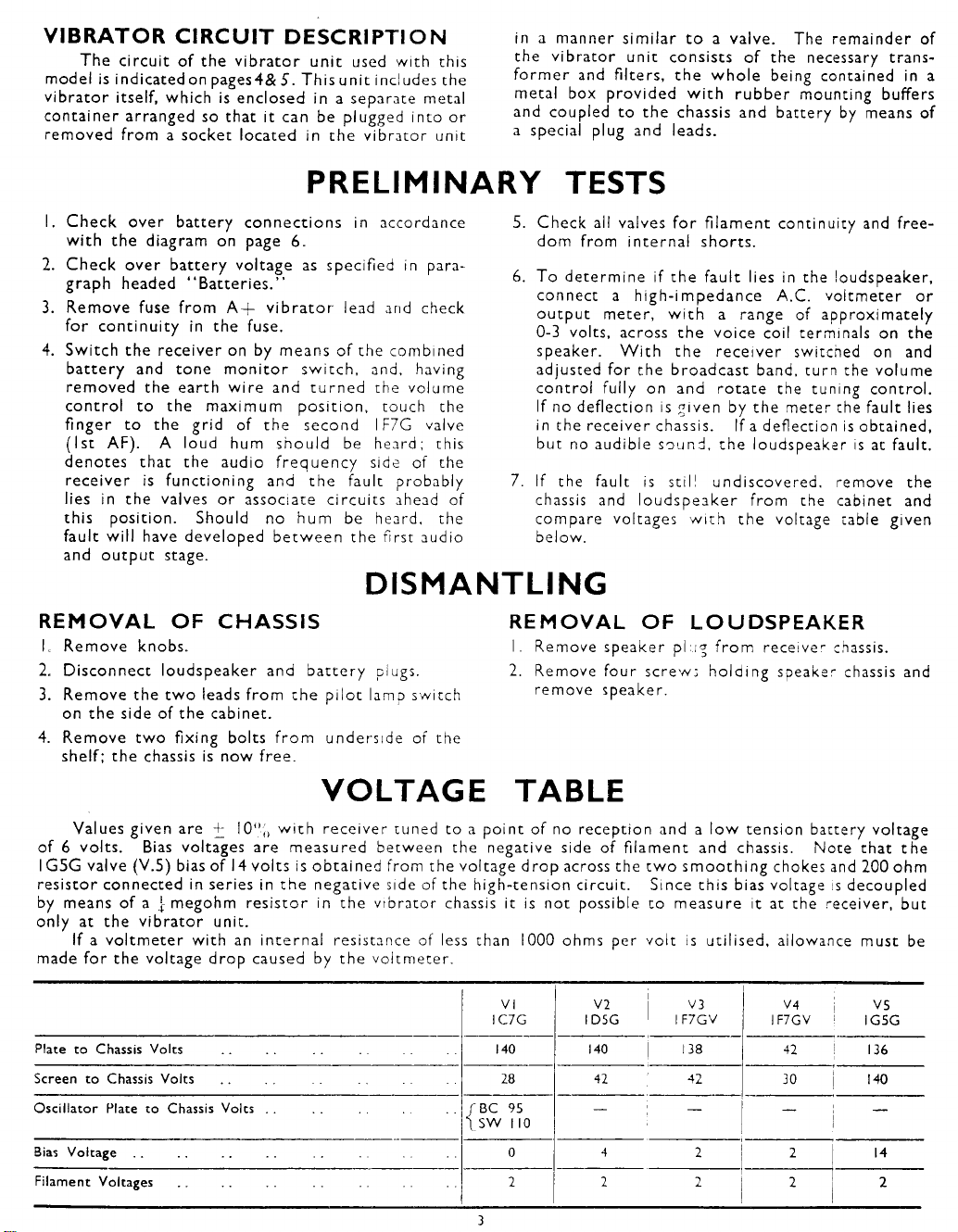
Values given are + 1 0 % w it h re ce iv er tuned to a po int of no recep tion and a l o w tension battery voltage
of 6 volts. Bias voltages are m eas ur ed be twe en the negative side of fila me nt and chassis. No te that t he
I G5 G v alve (V.5 ) bias of 14 volt s is ob tai ne d from the vo ltage d ro p across the t wo sm o o th in g chokes and 200 ohm
resis tor co nnec ted in series in t he nega tive side of the high-tension circuit. Since this bias voltage is de coupled
by means of a j- megohm res is to r in the vibrat or chassis it is not possible to m eas ur e it at the re ceiver, but
only at th e vi b ra to r unit.
If a vol tmet er w ith an in te rn a l resistance of less than 1000 ohms per volt is utilised, allowance must be
made f or the voltage drop caused by th e voltme te r.
VI
IC7 G
Plate to Chassis Volts 140 140 138
Screen to Chassis Volts 28 42 42
Oscilla to r Plate to Chassis Volts r BC 95
Bias Voltage
Filament Voltages 2 2 2
\ SW 1 10
0
3
V2
ID5 G
-
4
V3
IF7 GV
—
2
V4
IF7GV
42 136
30 140
— —
2 14
2 2
VS
IGSG
 Loading...