

The Galley IBT-D-RSS-AU Installation Guide

Galley BarTap® Installation Guide
THEGALLEY®TA P
Before You Begin Installation
INSTALLATION WARNING: NEVER USE TEFLON TAPE FOR OUT-OF-THE-WALL THREADED CONNECTIONS. USE
PROVIDED RUBBER GASKETS ONLY. NOT COMPLYING WITH THIS INSTRUCTION COULD DAMAGE THE PRODUCT
AND GENERATE LEAKAGE.
1. Observe all local plumbing codes.
2. Turn o water supply.
3. Inspect water supplies for signs of damage. Replace if necessary.
4. DO NOT use petroleum-based products on this faucet.
Tools
#2 & #3 PHILLIPS SCREWDRIVERS ADJUSTABLE WRENCH ADJUSTABLE PLIERS
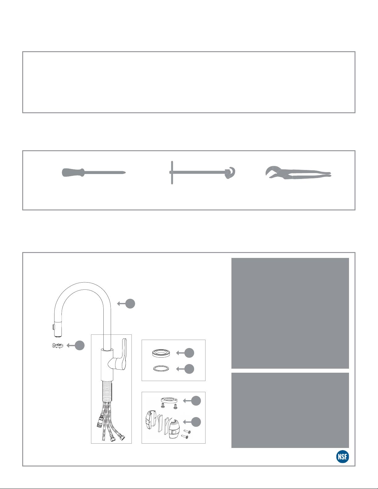
Package Contents
1
Remove all contents from the package and
identify before installation.
1 - Aerator Key
2 - Faucet
2
1
3
4
5
6
3 - Optional Base Ring
4 - Stainless Steel Mounting Washer
5- Stainless Steel Mounting Nut with Two
Crosshead Screws
6- Counterweight with two rubber strips
Note: All Hoses come pre-installed into Faucet and
are water tested at the factory.
TECHNICAL INFORMATION
Recommended Pressure Range: 20PSI 75PSI
Maximum Flow Rate: l.8GPM / 6.8L /min
Maximum Temperature: 150° F
Product is Certified to NSF/ ANSI 372 and conforms with
the lead content requirements for “lead free” plumbing as
e defined by California, Vermont, Maryland, and Louisiana
state laws and the U.S. Safe Drinking Water Act. This
faucet complies with ASME 112.18.1-2018/CSA B125.1-2018
requirements.
1
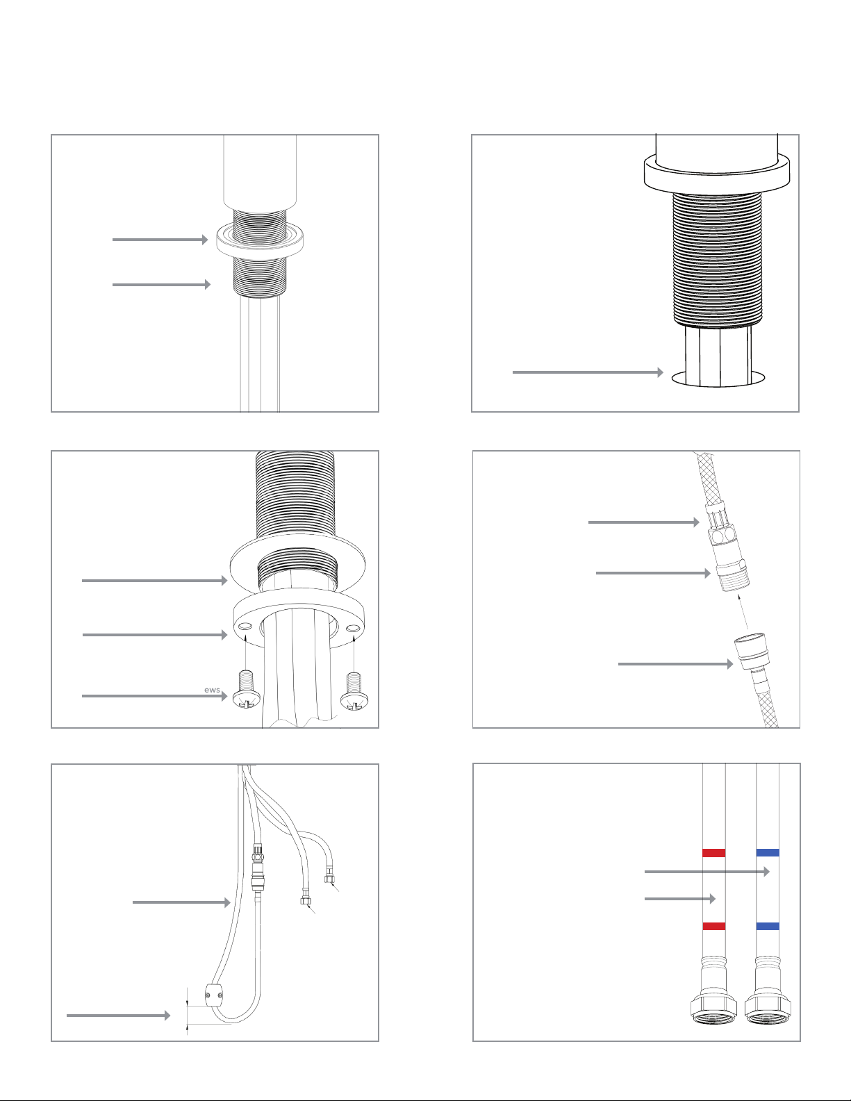
Installation
Step 1
The Galley BarTap® comes with
an Optional Base Ring. It can be
installed with the Base Ring or
without it.
Optional Base Ring
Mounting Shank
Step 3
On the underside of the counter
top, install the stainless steel
Washer and Mounting Nut by
slipping them over the hoses
and threading the nut onto the
Mounting Shank. Tighten the
Mounting Nut against the counter
top and tighten the two screws so
the faucet is secure.
Stainless Steel Washer
Step 2
Insert all hoses and Mounting
Shank through the hole in counter
top.
Ø 1-3/8” drill hole in counter top
Ø 1- 1/2” fast water jet hole in
counter top
Step 4
Connect the Hand Spray Hose to the
Hand Spray Supply Hose on which
the Check Valve housing is fitted.
Hand Spray Supply Hose
Check Valve Housing
Stainless Steel Mounting Nut
Stainless Steel Crosshead Screws
Step 5
Install the Counterweight onto the
Hand Spray Hose as shown.
Proper placement of the
Counterweights is critical for the
proper retraction of the spray hose.
Hand Spray Hose
VERY IMPORTANT!
1”
Hand Spray Hose
Note: make sure the Hand Spray Hose and
Counterweight are free to extend or retract and
are not in conflict with any plumbing components
or items under the sink or Workstation.
Step 6
Before connecting the hot and cold
Supply Hoses, flush water supply
stops to clear any debris. Place
a bucket underneath the stops
and run water for 5 to 10 seconds.
Carefully turn on the water.
Carefully position hot and cold
supplies so they will not interfere
with other hoses.
C
H
Connect the 3/8” Compression
Connections (Hot and Cold Supply
Hoses) to your hot and cold inlets.
Hoses are marked hot and cold.
Cold Supply
Hot Supply
2
 Loading...