

Page 1
!
GD3
Page 2
!
IMPORTANT!
Gas appliances must be installed to AS/NZS 5601.1:2013 by a qualified person and in accordance with these instructions. Failure to
install the appliance correctly will void your warranty and may cause a fire.
This fire should not be modified under any circumstances.
Under no circumstances should any combustibles such as paper, wood or
coal be used in this fire.
It is recommended that you have this fire serviced annually by a qualified technician.
Warranty repairs must be carried out by a Fire Dept. authorised technician.
This fire must ALWAYS terminate/flue outdoors.
Young children should be supervised to ensure that they do not play with the fire.
Clothing and other flammable materials should never be placed near the fire.
Never switch the fire on without the glass in place.
Please note that parts (near the flame) of this appliance, particularly the steel surrounding, glass panels to the face or the door,
become extremely hot during operation and can result in serious injury and burns if touched. It is therefore recommended that a
fireguard complying with BS 8423:2002 is used in the presence of young children, the elderly or infirm.
The Fire Dept. reserve the right to change all content contained herein and is subject to change without notice.
GD3 Installation Guide, Operating Instructions & Warranty
Step 1: Ensure all appliance components are correct and undamaged.
Step 2: Install plinth (if required).
Step 3: Install fire into cavity
Step 4: Install flue and connect to fire
Step 5: Connect and test electrical supply
Step 6: Connect gas supply and commission
Step 7: Lay the firebed
How to lay River Rocks firebed
How to lay Beach Driftwood firebed
How to lay Forest Logs firebed
Step 8: Show owner how to operate appliance.
Operating Instructions.
Trouble shooting
Warranty
Information in this installation guide may be subject to change without notice.
Please ensure that you have the current version before beginning installation.
If you have any queries, please contact The Fire Dept. on 0800 888 550
The GD3 fire installation process consists of 8 steps
Page
3
3
3
8
8
11
12
15
16
17
19
19
19
20
21-3-2017 VERSION 4 Page of 2 20
Page 3
!
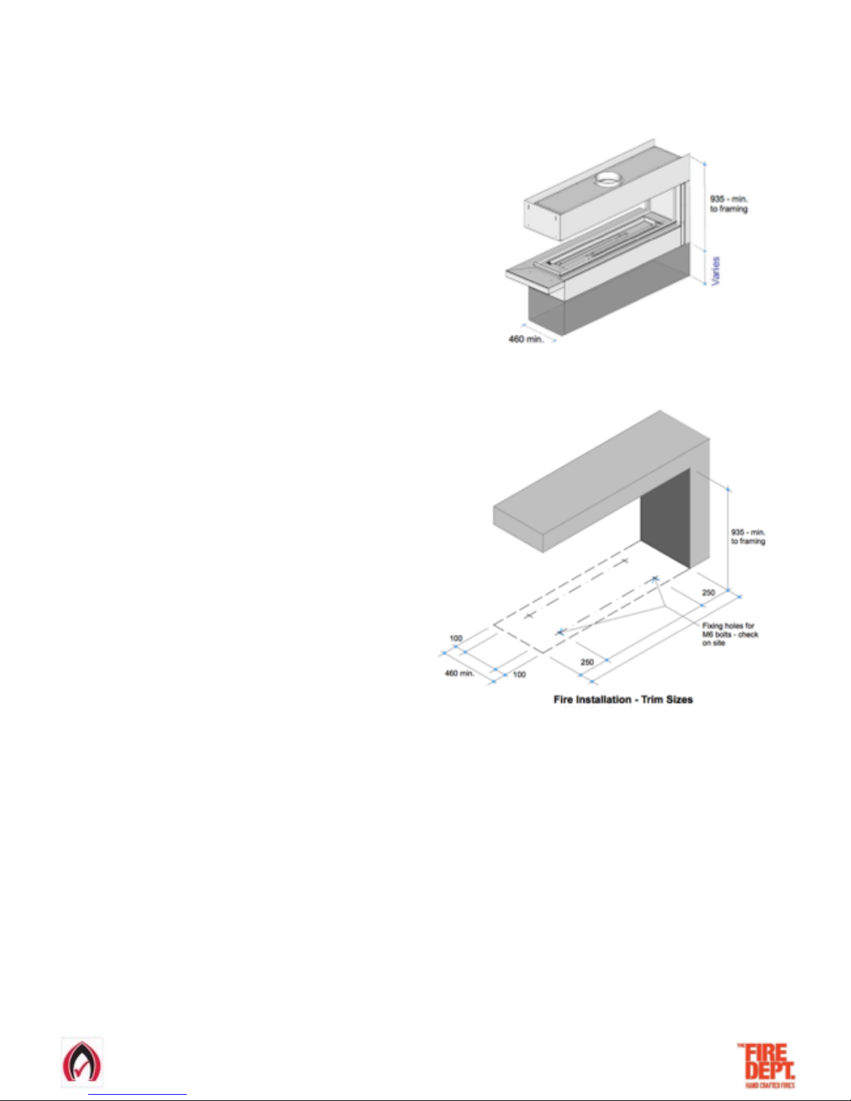
• Before installation, confirm all minimum clearances
from the outside surfaces of the fire to the surrounding
enclosure are no closer than 25mm from combustible
materials and 5mm from non-combustible materials.
• The exception to these minimum clearances is the base,
which can safely sit directly upon combustible (eg. timber)
and non-combustible (eg. concrete) materials.
• If a gas supply pipe has already been run to the cavity, ensure 1000mm of 3/8 soft copper tube is available at lower side of the
cavity, as this is where the copper tube with the gas supply enters the fire.
• If an electrical supply cable has already been run to the cavity (must be a minimum of 1.0mm 4 core cable), ensure cable reaches
the lower side of the cavity, as this is where it will enter the fire.
• In order to access the fixing slots in the base of the fire, and the gas and electrical connections, it is necessary to first remove the
glass and the burner tray.
Step 1: Unpack and ensure all components are correct and undamaged
• Firebox
• Box of firebed mediums
• Flue kit
Step 2: Install plinth (if required)
• If the fire is to sit on a plinth, ensure it is capable of
supporting a 200kg load.
• There is no clearance requirement for the base of the fire.
It may safely sit directly upon combustible (eg. timber)
and non-combustible (e.g. concrete) materials.
Step 3: Install fire into cavity
21-3-2017 VERSION 4 Page of 3 20
Page 4
!
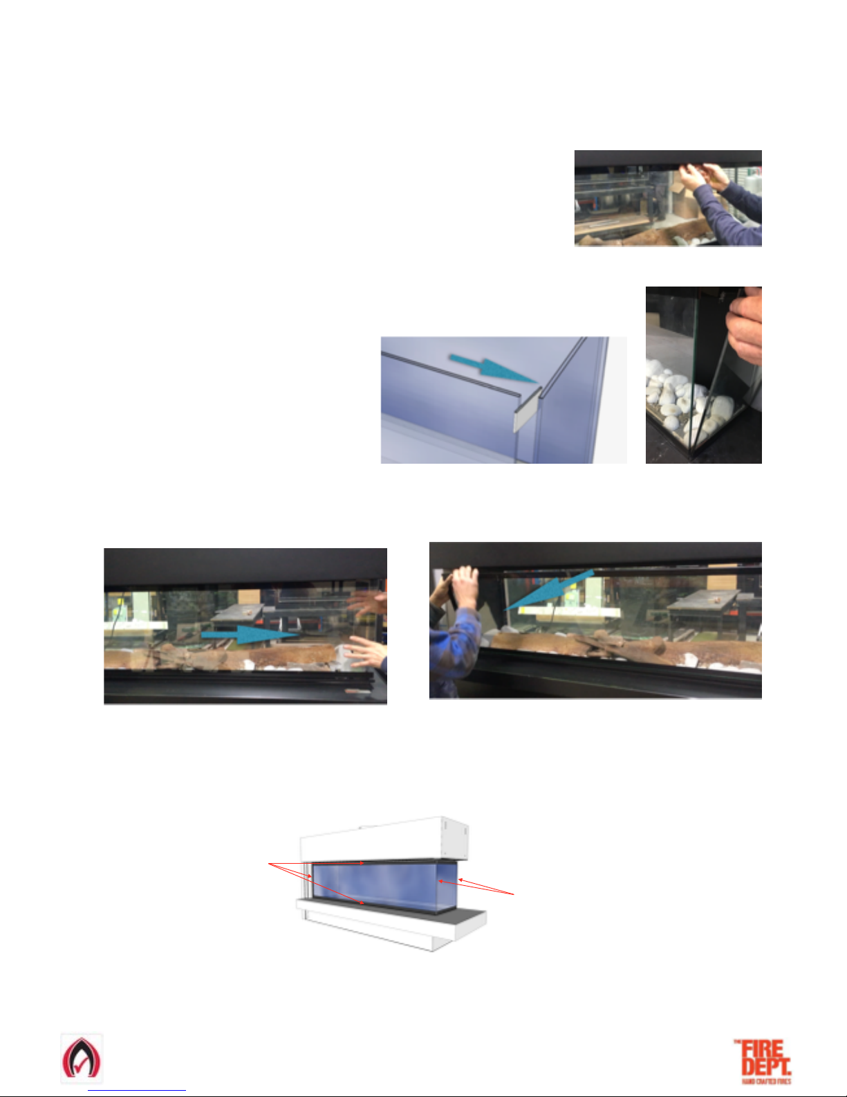
• Note: glass removal is best carried out by two people.
• Carefully remove glass, which is held in place by powerful magnets in each corner
• Glass removing tool is located as shown and held in place with a magnet
• Carefully lever open one side of the top of the end glass then remove the glass from the fire as shown
• In one movement slide the side glass towards the open end of the fire and off the fixing magnets. Take care that glass doesn't fall
completely off once its free from the fixing magnets then lower the top of the glass first and pull it away from the fire.
• To replace the glass repeat the removal process in reverse.
• Please note that the glass face that forms the 90º butt joint should not include the black edge banding.
Glass edge banding
No glass edge banding
• Lift glass away from fire and lay flat in a safe place with insulating material facing down to protect glass.
21-3-2017 VERSION 4 Page of 4 20
Glass removal process
Page 5
!
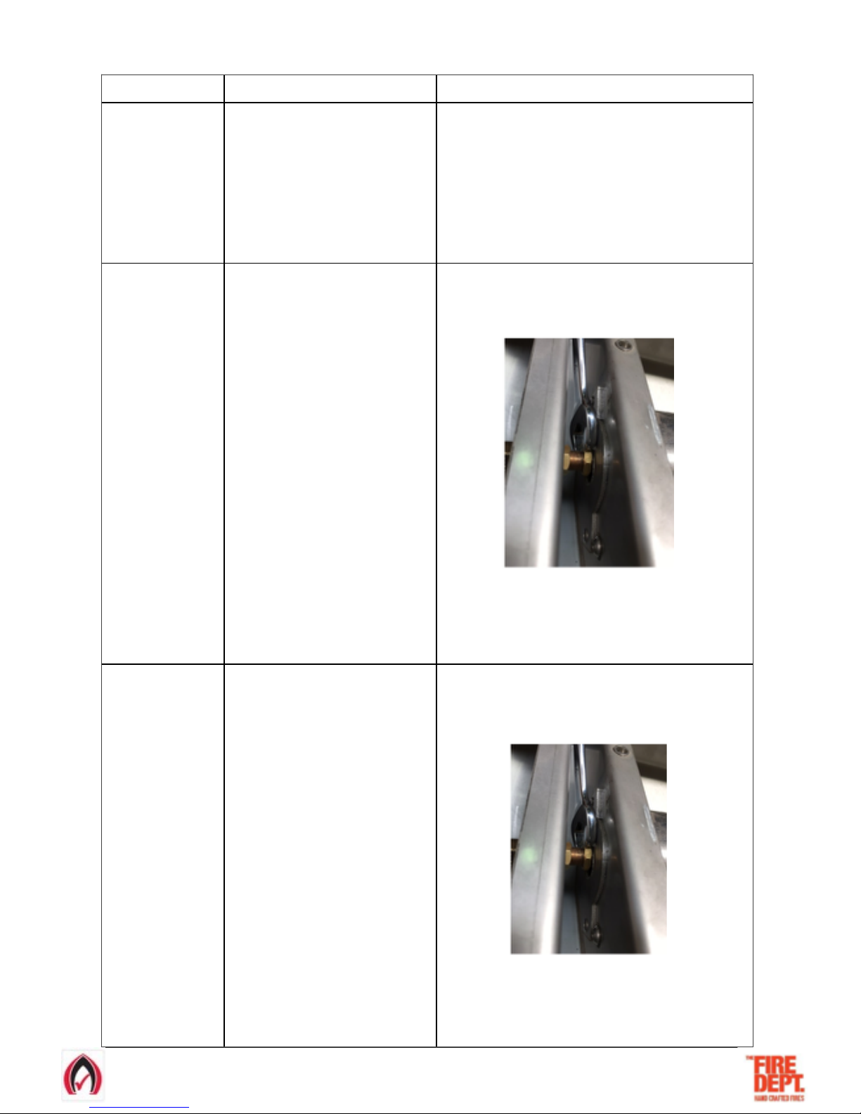
GD3 1200
This model has one
gas injector at the
right hand side of
the burner tray.
21-3-2017 VERSION 4 Page of 5 20
LPG
Natural Gas
• Remove the stainless steel burner end
caps (2 x screws on each cap) at either
end of the burner tray.
• Remove the burner tray by carefully
pushing it away from the pilot and lift the
pilot end of the burner tray, lift the burner
tray up and away from the pilot in one
movement.
• Stand the burner tray on its end and lean
against a stable surface.
• Remove the stainless steel burner end caps (2 x screws on each
cap) at either end of the burner tray.
• Remove the burner tray by carefully pushing it away from the pilot
and lift the pilot end of the burner tray, lift the burner tray up and
away from the pilot in one movement.
• Stand the burner tray on its end and lean against a stable surface.
GD3 1500
This model has two
gas injectors at the
right and left hand
sides of the burner
tray.
• Remove the stainless steel burner end
caps (2 x screws on each cap) at either
end of the burner tray.
• Remove the burner tray by carefully
pushing it away from the pilot and lift the
pilot end of the burner tray, lift the burner
tray up and away from the pilot in one
movement. Ensure that the gas injector at
the left hand side is not damaged as the
burner tray is lifted out.
• Stand the burner tray on its end and lean
against a stable surface.
Burner Tray Removal Process
• Remove the stainless steel burner end caps (2 x screws on each
cap) at either end of the burner tray.
• On the left hand side gas injector, loosen and spin back the 12mm
brass nut closest to the burner tray.
LH Gas Injector
• Remove the burner tray by carefully pushing it away from the pilot
and lift the pilot end of the burner tray, lift the burner tray up and
away from the pilot in one movement.
•
Stand the burner tray on its end and lean against a stable surface.
GD3 1600
This model has two
gas injectors at the
right and left hand
sides of the burner
tray.
• Remove the stainless steel burner end
caps (2 x screws on each cap) at either
end of the burner tray.
• Remove the burner tray by carefully
pushing it away from the pilot and lift the
pilot end of the burner tray, lift the burner
tray up and away from the pilot in one
movement. Ensure that the gas injector at
the left hand side is not damaged as the
burner tray is lifted out.
• Stand the burner tray on its end and lean
against a stable surface.
• Remove the stainless steel burner end caps (2 x screws on each
cap) at either end of the burner tray.
• On the left hand side gas injector, loosen and spin back the 12mm
brass nut closest to the burner tray.
LH Gas Injector
• Remove the burner tray by carefully pushing it away from the pilot
and lift the pilot end of the burner tray, lift the burner tray up and
away from the pilot in one movement.
•
Stand the burner tray on its end and lean against a stable surface.
Page 6

!
21-3-2017 VERSION 4 Page of 6 20
• Slide fire into position and ensure that it complies with the minimum clearances required (25mm for combustibles, 5mm for non-
combustibles) to the surrounding enclosure.
• In order to provide maximum positioning flexibility, the base has four 30mm long slots.
• Mark out and drill fixing holes through the 30mm slots in the base. Ensure holes are drilled in the centre of the slots to allow
maximum positioning flexibility. Clear out any debris from drilling,
• Ensure the fire is level and pack up corners to suit where necessary. Fix bolts/screws into floor. Check and ensure unit is level.
• If the electrician and/or gas fitter is available at this stage the electrical supply and gas supply can be connected and tested/
commissioned (see steps 5 & 6).
• Replace the burner tray. The burner tray installation process depends upon the model and type of gas to be used. Refer to table
below.
Page 7
!
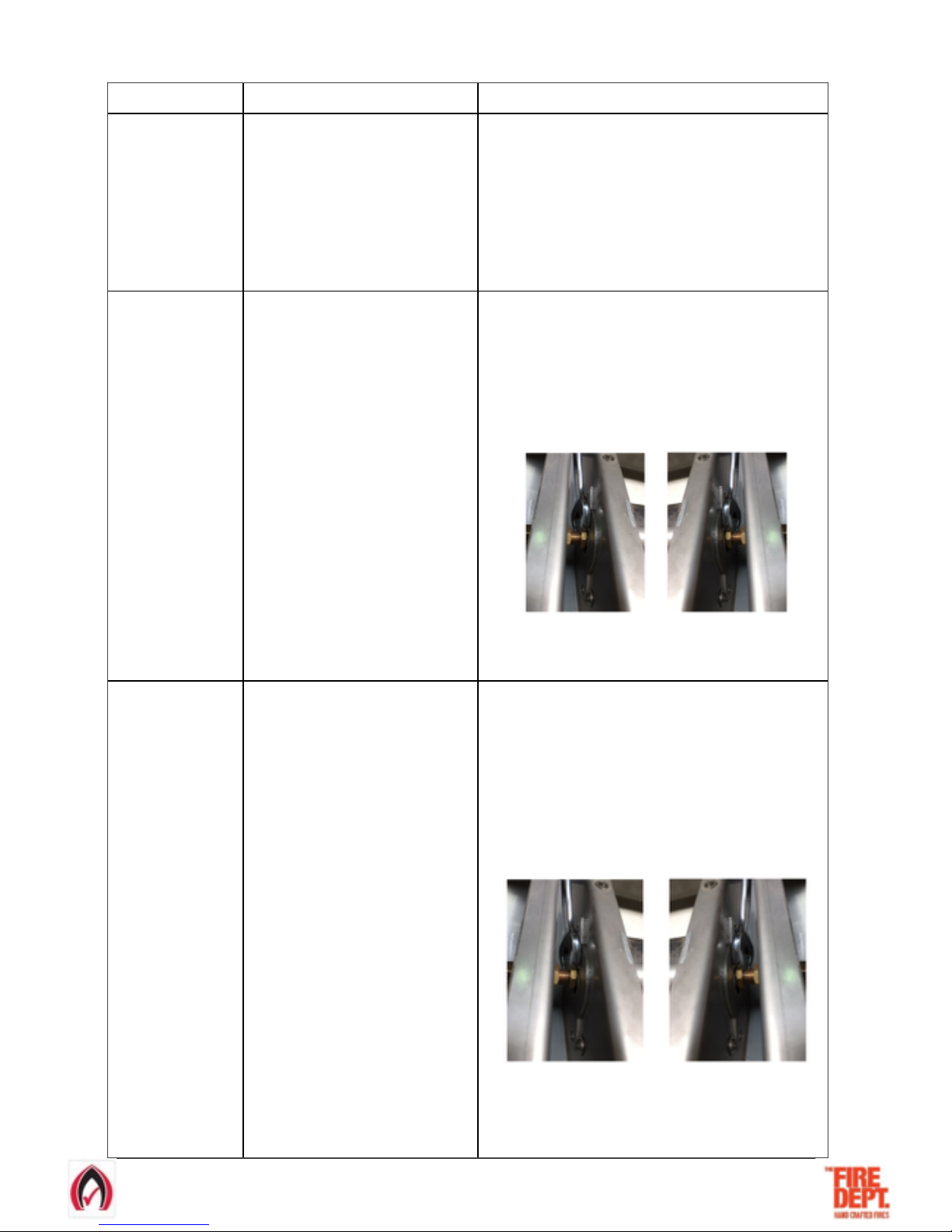
GD3 1200
This model has one
gas injector at the
right hand side of
the burner tray.
LPG
Natural Gas
•
Install the burner tray by carefully
lowering the end opposite from the pilot
meanwhile holding up the pilot end,
lower the burner tray down and move
towards the pilot in one movement.
•
Ensure the burner tray is located
correctly into the burner bracket and the
jets are aiming into the burner tube inlet
holes.
•
Replace the stainless steel burner end
caps (2 x screws on each cap) at either
end of the burner.
• Install the burner tray by carefully lowering the end opposite from
the pilot meanwhile holding up the pilot end, lower the burner tray
down and move towards the pilot in one movement.
• Ensure the burner tray is located correctly into the burner bracket
and the jets are aiming into the burner tube inlet holes.
• On the left hand side gas injector, gently tighten (do not
overtighten) the 12mm brass nut closest to the burner tray.
• Replace the stainless steel burner end caps (2 x screws on each
cap) at either end of the burner.
GD3 1500
This model has two
gas injectors at the
right and left hand
sides of the burner
tray.
• Install the burner tray by carefully lowering
the end opposite from the pilot meanwhile
holding up the pilot end, lower the burner
tray down and move towards the pilot in
one movement.
• Ensure the burner tray is located correctly
into the burner bracket and the jets are
aiming into the burner tube inlet holes.
•
Replace the stainless steel burner end
caps (2 x screws on each cap) at either
end of the burner.
GD3 1600
This model has two
gas injectors at the
right and left hand
sides of the burner
tray.
• Install the burner tray by carefully lowering
the end opposite from the pilot meanwhile
holding up the pilot end, lower the burner
tray down and move towards the pilot in
one movement.
• Ensure the burner tray is located correctly
into the burner bracket and the jets are
aiming into the burner tube inlet holes.
•
Replace the stainless steel burner end
caps (2 x screws on each cap) at either
end of the burner.
• Install the burner tray by carefully lowering the end opposite from
the pilot meanwhile holding up the pilot end, lower the burner tray
down and move towards the pilot in one movement.
• Ensure the burner tray is located correctly into the burner bracket
and the jets are aiming into the burner tube inlet holes.
• On both the left and right hand gas injectors, gently tighten (do not
overtighten) the 12mm brass nuts closest to the burner tray.
LH Gas Injector RH Gas Injector
• Replace the stainless steel burner end caps (2 x screws on each
cap) at either end of the burner.
Burner Tray Installation Process
21-3-2017 VERSION 4 Page of 7 20
• Install the burner tray by carefully lowering the end opposite from
the pilot meanwhile holding up the pilot end, lower the burner tray
down and move towards the pilot in one movement.
• Ensure the burner tray is located correctly into the burner bracket
and the jets are aiming into the burner tube inlet holes.
• On both the left and right hand gas injectors, gently tighten (do not
overtighten) the 12mm brass nuts closest to the burner tray.
LH Gas Injector RH Gas Injector
• Replace the stainless steel burner end caps (2 x screws on each
cap) at either end of the burner.
Page 8
!
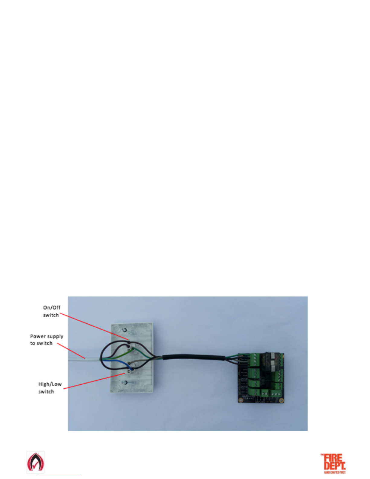
• Flue installation must meet the requirements of AS/NZS 5601.1:2013 must comply with all local council requirements and
be installed and certified by a suitably qualified person.
• Refer to appropriate Fire Dept product specification for specific minimum requirements.
• A 25mm clearance from combustible materials and a minimum of 5mm from non-combustible is required when installing a flue
system for any fire supplied by The Fire Dept.
• The flue installation requires a restriction free cavity from the top of the firebox (flue spigot) to the outside atmosphere.
• Air flow must be unobstructed from the firebox to inner flue & from the heat shield to outer casing allowing air to circulate from the
firebox to the flue casings to the atmosphere.
21-3-2017 VERSION 4 Page of 8 20
Step 4: Install flue and connect to fire
• All electrical connections must meet the requirements of AS/NZS standards and be installed and certified by a
suitably qualified person.
• In order to access the electricals, it is necessary to first remove the glass and the burner tray.
• Note: glass removal is best carried out by two people.
•Follow the ‘Glass removal process’ in page 4
• Lift glass away from fire and lay flat in a safe place with insulating material facing down.
• Remove the burner tray by following the ‘Burner Tray Removal Process’ in Step 3 of this guide.
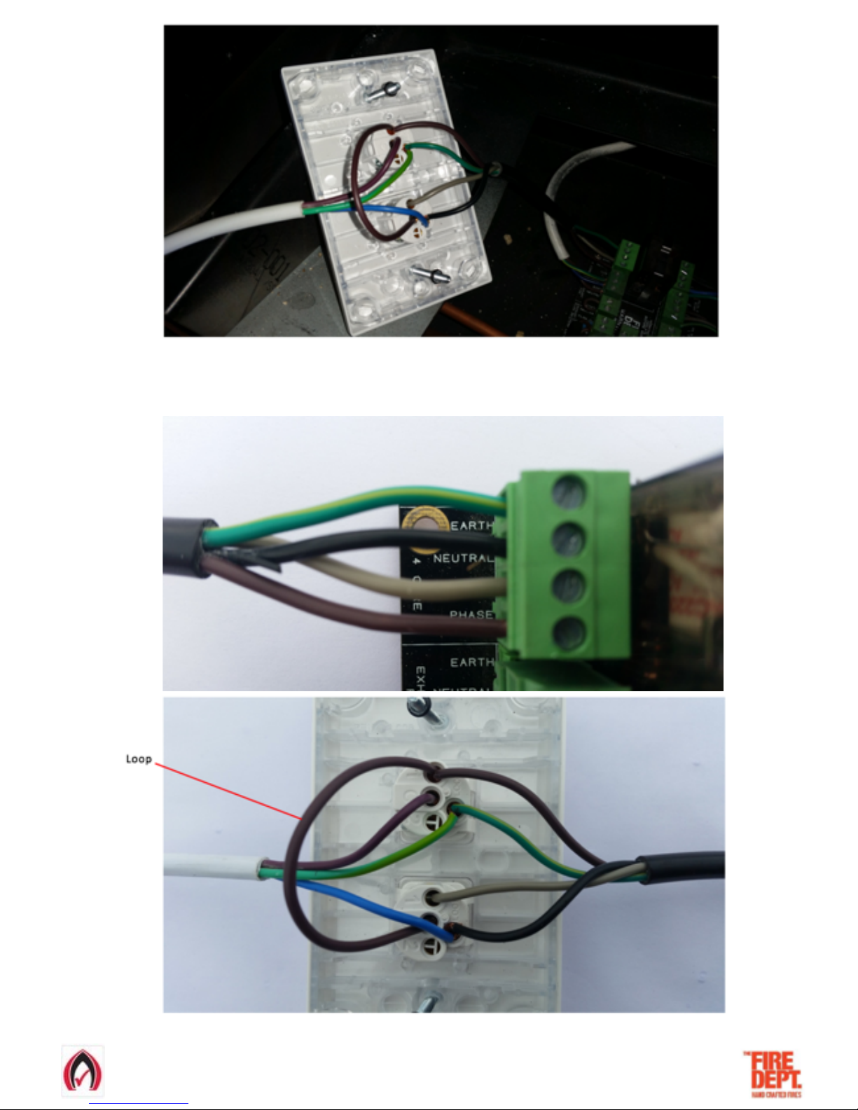
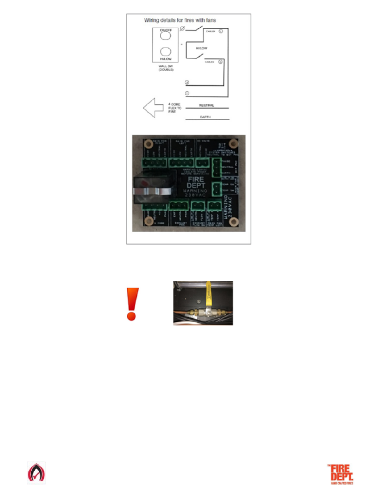
• With the burner tray removed, example electrical connections between the fire and the switch can be seen, using 4 core
(minimum 1mm) cable.
• The supplied switch can either be used, or discarded.
Step 5: Connect and test electrical supply
Page 9
!
21-3-2017 VERSION 4 Page of 9 20
Overview of electrical connections
Electrical connections detail
Page 10
!
21-3-2017 VERSION 4 Page of 10 20
• Following these connection details, using the 4 core cable that has been run at site, connect the switch to the fire.
• IMPORTANT: Before testing, ensure the gas valve is turned off.
• Test electrical functions by switching the bottom High/Low switch to LOW, then switch the fire ON using the top On/Off switch.
• The fan will start and after approximately five seconds, the pilot will spark. Because the gas supply is turned off, the pilot will spark
for approximately five seconds then automatically switch off. The fan will continue running.
• NOTE: GD3 models have a fan which runs in both LOW and HIGH settings.
• Switch to HIGH setting. Ensure that a red light appears on electrical connections block and the fan is running.
• Switch fire off. Electrical testing is complete.
• Replace the burner tray by following the ‘Burner Tray Installation Process’ in Step 3 of this guide.
• Carefully replace glass by simply reversing the glass removal process.
Page 11
!
• Gas installation, connection and commissioning must meet the requirements of AS/NZS 5601.1:2013 and be
installed and certified by a suitably qualified person.
• In order to access the gas supply and testing area, it is necessary to first remove the glass and the burner tray.
• Note: glass removal is best carried out by two people.
•Follow the ‘Glass removal process’ in page 4
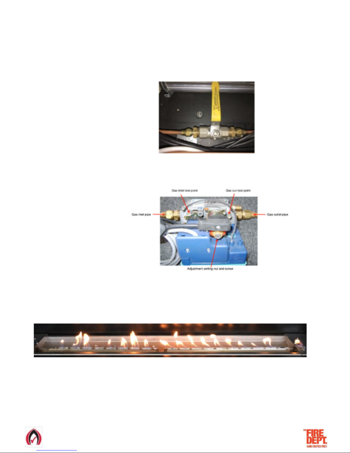
• Connect 3/8 soft copper pipe to main valve.
• Leak test all joints.
• Switch fire on.
• Test/adjust high first and then the low pressures against rating plate specifications.
• In the unlikely event that the rating plate is not attached Do Not commission the fire and contact The Fire Dept immediately.
• Switch fire off.
• Replace the burner tray by following the ‘Burner Tray Installation Process’ in Step 3 of this guide.
• Switch fire on.
• Note: due to lack of firebed and glass, it may be necessary to manually light burners.
• Switch fire off
• Lay firebed in accordance with instructions in Step 7 of this guide.
• Carefully replace glass by simply reversing the glass removal process.
• Send gas certificate to appropriate person.
Step 6: Connect gas supply and commission
21-3-2017 VERSION 4 Page of 11 20
Page 12
!
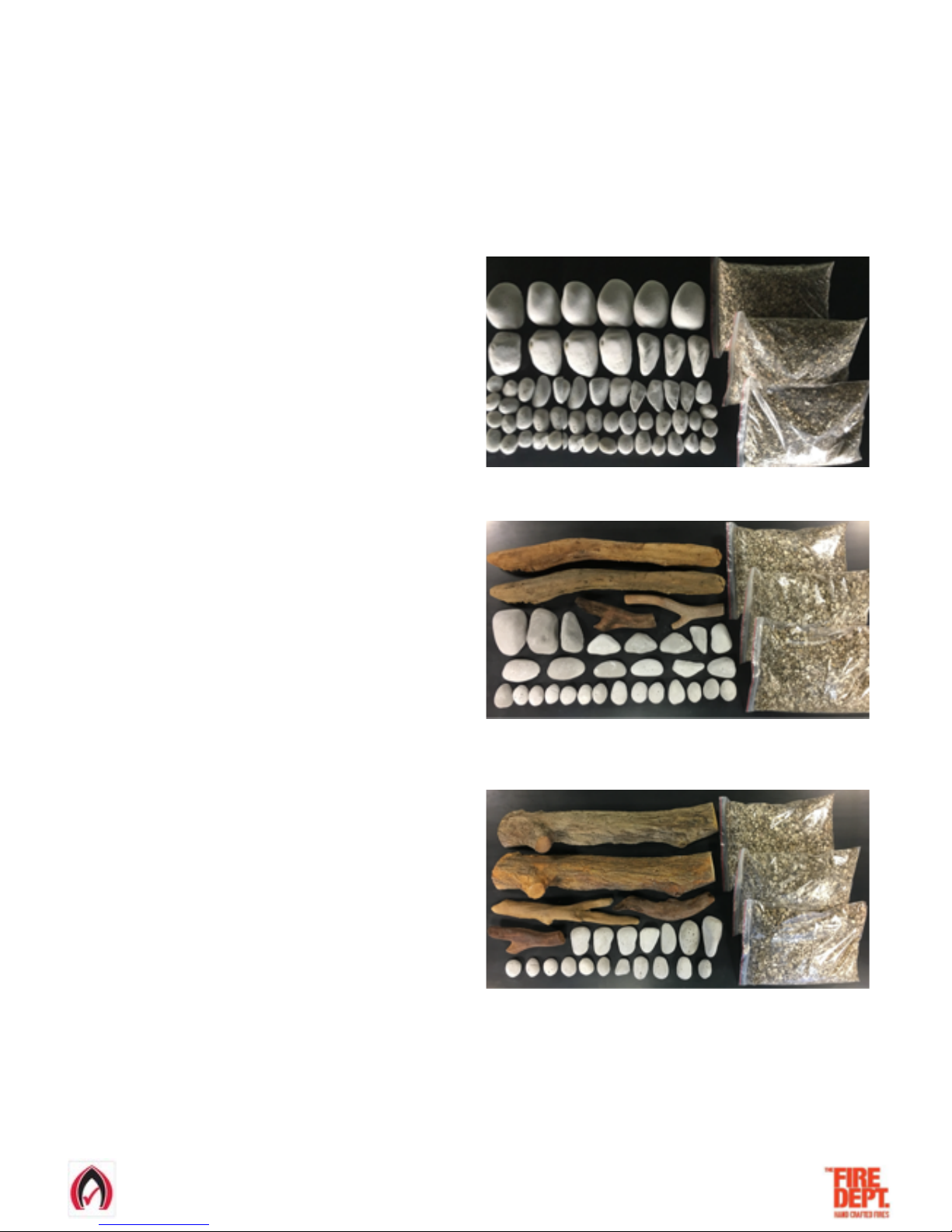
•The GD3 has three firebed options: River Rocks, Beach Driftwood & Forest Logs.
• Particular care should be taken when placing the chosen firebed mediums into the burner tray. Failure to place the medium
correctly may result in the fire performing inefficiently.
• Open the firebed cardboard box and identify firebox mediums.
River Rocks option has two firebed mediums:
Vermiculite – 3 bags
White rocks – large and small
.
Beach Driftwood option has three firebed mediums:
Vermiculite – 3 bags
White rocks – large and small
Driftwood – large and small
Forest Logs option has three firebed mediums:
Vermiculite – 3 bags
White rocks – large and small
Four logs – large and small
Step 7: Lay the firebed
21-3-2017 VERSION 4 Page of 12 20
Page 13
!
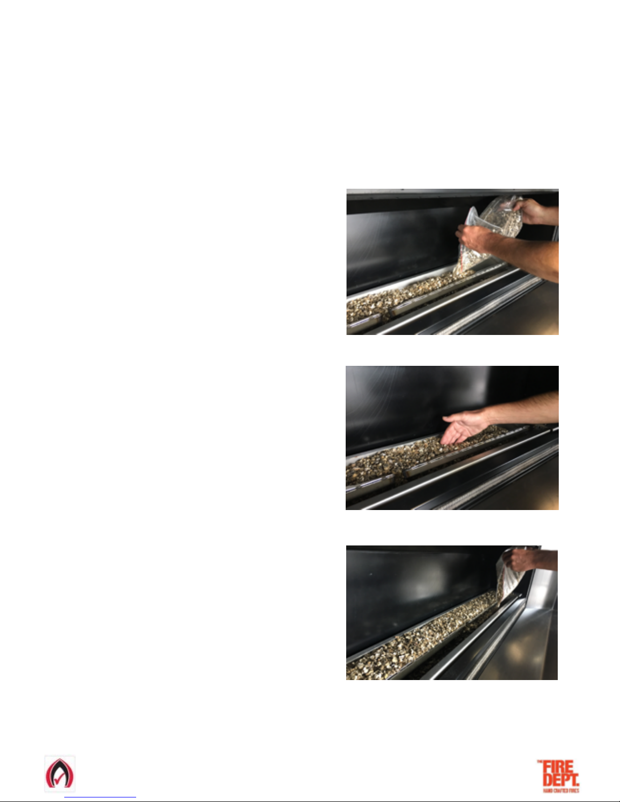
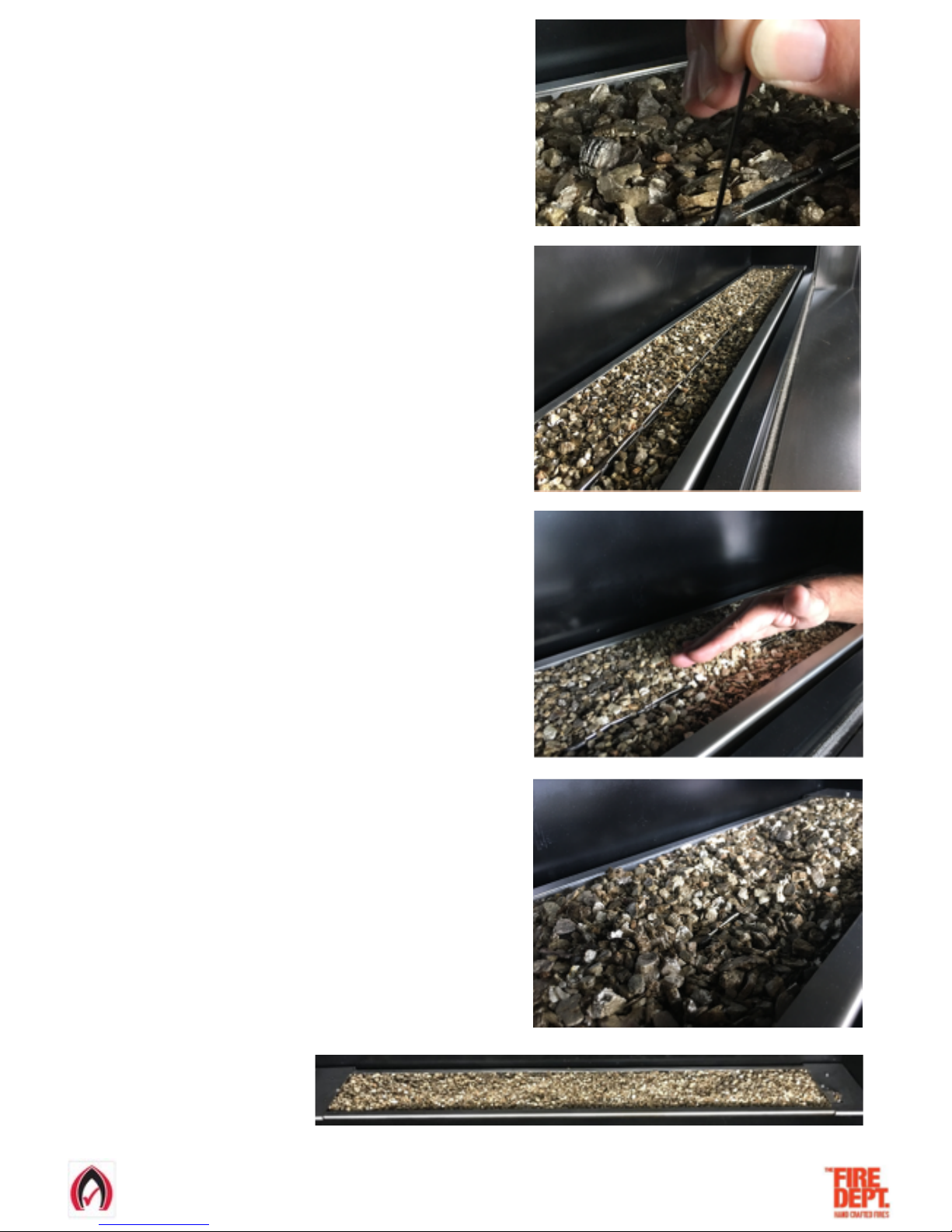
How to lay Vermiculite
• In order to access the burner tray, it is necessary to first remove the glass.
• Note: glass removal is best carried out by two people.
•Follow the ‘Glass removal process’ in page 4
• Lift glass away from fire and lay flat in a safe place with insulating material facing down.
21-3-2017 VERSION 4 Page of 13 20
• Beginning in the middle at the back of the burner,
carefully empty the bags of vermiculite into the
burner tray.
• Ensure not to spill any vermiculite in cavities
in front of and behind burner tray.
• Do not pour vermiculite directly into burner slots.
• Fill area behind burner up to top of burner tray.
Use hand to spread out and push under burner.
• Fill up area in front of burner and gently pat
down vermiculite to ensure it is spread evenly
throughout the burner tray.
Page 14
!
• Using a small Allen key (or similar), remove any
vermiculite that may have fallen into burner slots.
• If natural gas in being used, leave burner slots
slightly exposed.
• If LPG is being used, lightly cover burner slots
in a thin layer of vermiculite by adding at back
of burner tray and gently sweeping forward.
• If LPG is being used, small burner slots should
be just visible.
• Vermiculite layer complete
21-3-2017 VERSION 4 Page of 14 20
Page 15
!
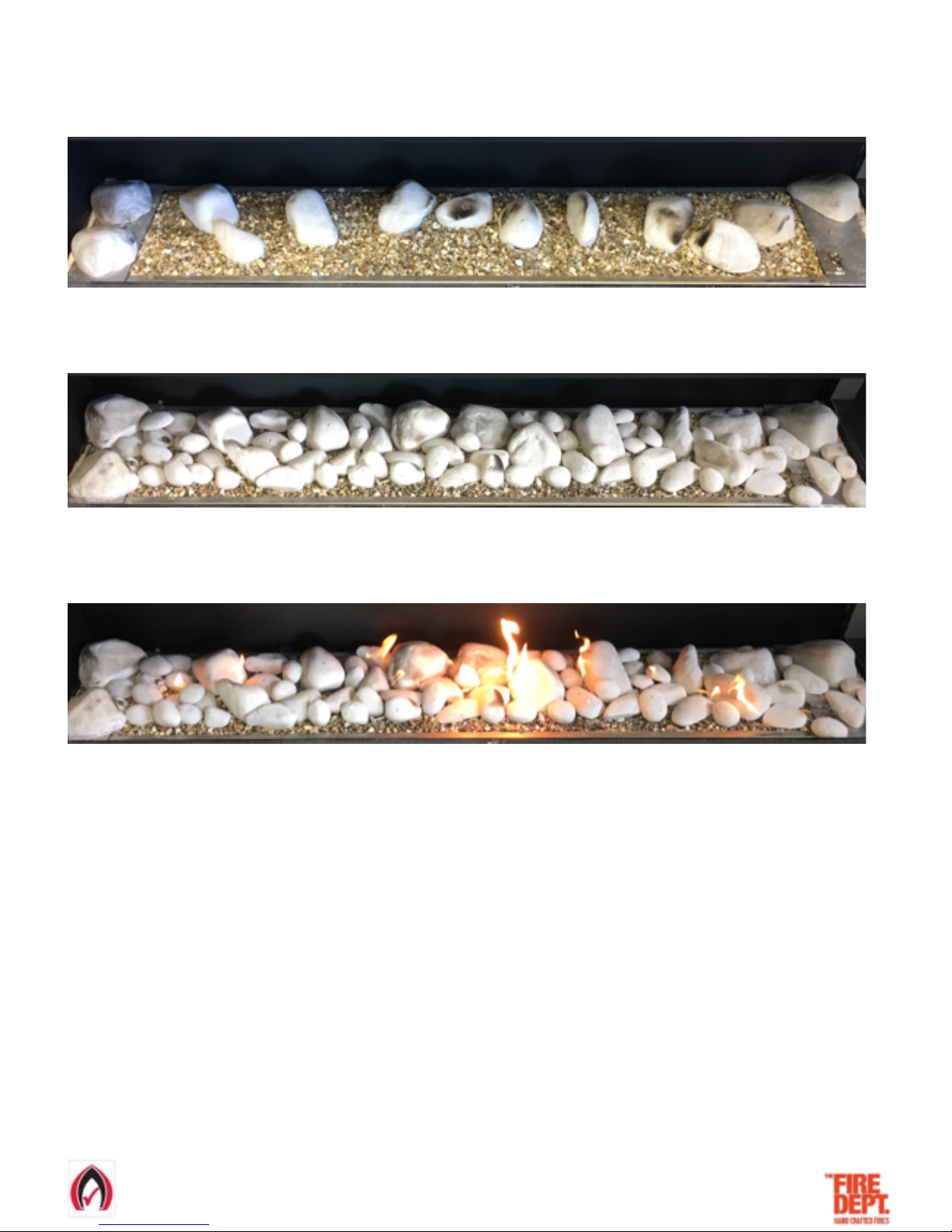
• Lay large rocks first, in these positions.
• Lay small rocks next, in these positions.
• With glass still removed, switch fire on at ‘HIGH’ setting to check how flame looks. The flame will take 10-20 seconds to light fully.
• IMPORTANT: the flame effect should look natural and non-uniform, running the entire length of the burner.
• Common flame effect issues are:
o Flame touching edge of burner tray.
o Missing flames along length of burner.
• Both these issues can be resolved by switching the fire off and slightly repositioning rocks and logs at the problem areas.
• Repeat this switching on/off and repositioning until a natural and non-uniform flame effect is achieved.
• Once a natural and non-uniform flame effect is achieved, switch fire to ‘LOW’ setting and ensure the flame effect, although smaller,
still looks good.
• Switch fire off and carefully replace glass by simply reversing the glass removal process.
• Switch the fire on and check that flame effect still looks natural and non-uniform.
• Note: it is normal for the glass to mist a little when fire is first switched on. This will quickly disappear.
How to lay River Rocks Firebed
21-3-2017 VERSION 4 Page of 15 20
Page 16
!
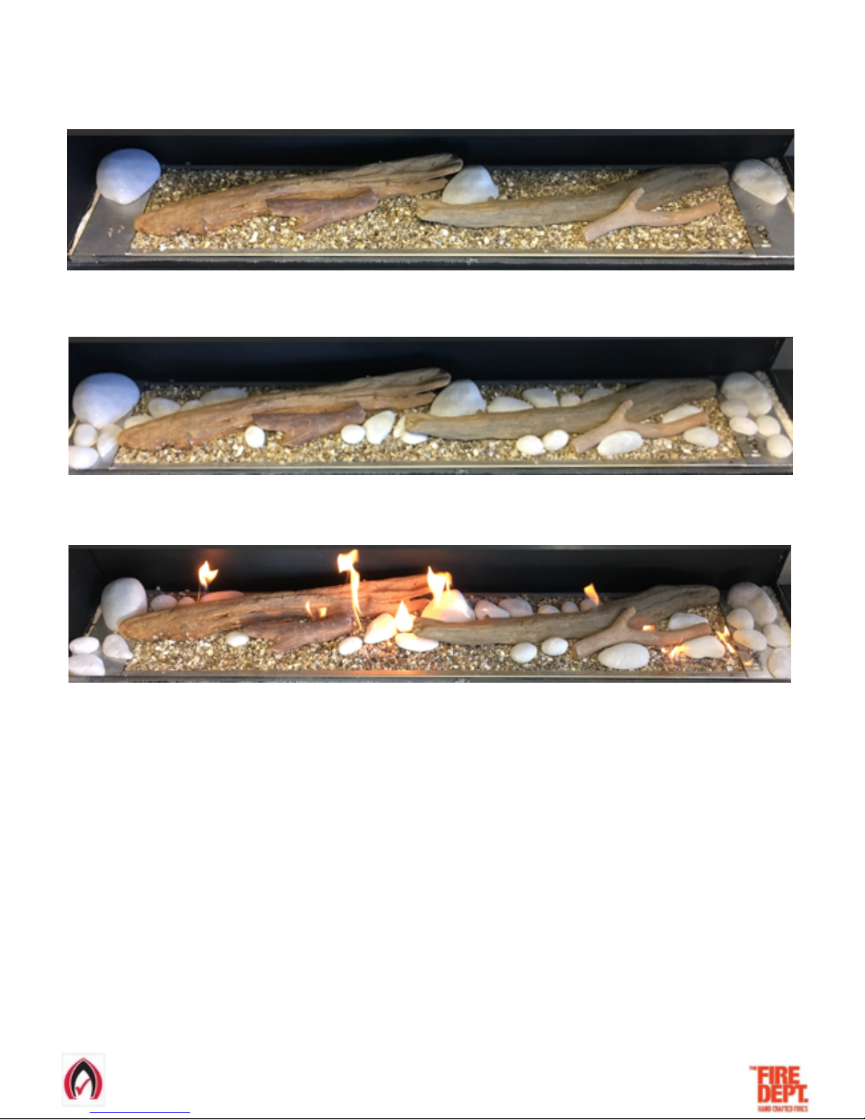
• Lay logs and large rocks first, in these positions.
• Lay rocks next, in these positions.
• With glass still removed, switch fire on at ‘HIGH’ setting to check how flame looks. The flame will take 10-20 seconds to light fully.
• IMPORTANT: the flame effect should look natural and non-uniform, running the entire length of the burner.
• Common flame effect issues are:
o Flame touching edge of burner tray.
o Missing flames along length of burner.
• Both these issues can be resolved by switching the fire off and slightly repositioning rocks and logs at the problem areas.
• Repeat this switching on/off and repositioning until a natural and non-uniform flame effect is achieved.
• Once a natural and non-uniform flame effect is achieved, switch fire to ‘LOW’ setting and ensure the flame effect, although smaller,
still looks good.
• Switch fire off and carefully replace glass by simply reversing the glass removal process.
• Switch the fire on and check that flame effect still looks natural and non-uniform.
• Note: it is normal for the glass to mist a little when fire is first switched on. This will quickly disappear.
How to lay Beach Driftwood Firebed
21-3-2017 VERSION 4 Page of 16 20
Page 17
!
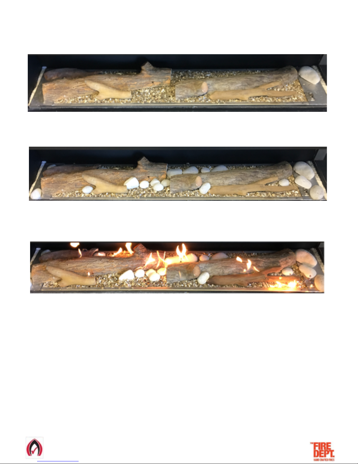
• Lay logs and large rocks first, in these positions.
• Lay rocks next, in these positions.
• With glass still removed, switch fire on at ‘HIGH’ setting to check how flame looks. The flame will take 10-20 seconds to light fully.
• IMPORTANT: the flame effect should look natural and non-uniform, running the entire length of the burner.
• Common flame effect issues are:
o Flame touching edge of burner tray.
o Missing flames along length of burner.
• Both these issues can be resolved by switching the fire off and slightly repositioning rocks and logs at the problem areas.
• Repeat this switching on/off and repositioning until a natural and non-uniform flame effect is achieved.
• Once a natural and non-uniform flame effect is achieved, switch fire to ‘LOW’ setting and ensure the flame effect, although smaller,
still looks good.
• Switch fire off and carefully replace glass by simply reversing the glass removal process.
• Switch the fire on and check that flame effect still looks natural and non-uniform.
• Note: it is normal for the glass to mist a little when fire is first switched on. This will quickly disappear.
How to lay Forest Logs Firebed
21-3-2017 VERSION 4 Page of 17 20
Page 18

!
Step 8: Show owner how to operate fire
•Following the GD3 Operating Instructions on the next page, show the owner how to switch the fire on and off, and how to switch
between high and low settings.
• If the owner is not available, leave this manual by the fire.
21-3-2017 VERSION 4 Page of 18 20
NOTES:
Page 19
!
• "Press the on/off switch to the ON position. #
• "Press the high/low switch to the HIGH position. #
• "The electronic solenoid pack will start to click. #
• "Gas will then be released and ignited at the pilot valve. #
• "The safety sensor will allow the main burner pipe to ignite and flames will appear. The whole process will take between 10-20 seconds. #
• "Once the flame appears, it can be turned down to the low setting by pressing the high/low switch to LOW. #
GD3 OPERATING INSTRUCTIONS
To shut down fire:
• "Press the on/off switch to the OFF position. #
TROUBLE SHOOTING
PROBLEM
PROBABLE CAUSE
CORRECTION
Appliance doesn't start
1.
No gas supply
2.
No power supply
3.
Low or poor pilot flame
4.
Signal from flame rectifier interrupted
5.
Signal to sparker electrode interrupted
6.
Incorrect sparker electrode gap
1.
Check gas supply
2.
Check power supply
3.
Check flame size and pressure
4.
Check flame rectifier and wire to sit pack
5.
Check sparker gap and wire to sit pack
6.
Check sparker electrode gap is 3mm
Appliance shuts down
1.
Low gas supply
2.
Low or poor pilot flame
3.
Signal to flame rectifier interrupted
1.
Check gas supply
2.
Check flame size and pilot flame pressure
3.
Check flame rectifier and wire to sit pack
Flame in not running the full length
of the burner
1.
The firebed is not aligned to the
burner
1.
Reset the firebed to the specific model
SPECIFICATIONS.
Flame is yellow and sooty
1.
Primary aeration ports have a
blockage
1.
Check primary aeration ports for
blockage and clear if required
No flame at the pilot
1.
Primary aeration ports have a
blockage
1.
Check primary aeration ports for
blockage and clear if required
21-3-2017 VERSION 4 Page of 19 20
The GD3 fire has been designed to be simple to use. It is controlled by a wall switch, which must be installed by a qualified electrician.
Page 20

PRODUCT WARRANTY
IMPORTANT: Evidence of original purchase is required for warranty service.
WARRANTOR: The Fire Dept (Landscape Elements Ltd)
85 Newton Road
Mount Maunganui#
PO Box 10275, Bayfair, Mount Maunganui
WARRANTY
This warranty will be deemed invalid if the Product is;
(A) Installed by someone other than an authorised Fire Dept agent.
(B) Not operated appropriately or “over-fired” in a manner resulting in the firebox operating excessively hot.
(C) Not serviced and maintained by a certified gas fitter every 12 months.
(D) Damaged by accident, neglect or misuse,
(E) Repaired by someone other than an authorised Fire Dept repair agent for a defect or malfunction covered by this warranty.
(F) Modified, altered or used as part of any conversion kits, subassemblies, or any configurations not sold by The Fire Dept.
(G) The product contains fire bricks and has not been subjected to the recommended first start-up and run-in procedure.
(H) Used in conjunction with any equipment or parts or as part of a system not manufactured or supplied by The Fire Dept.
( I ) External powder-coating within 200m of the high tide mark and not lightly washed with warm soapy water every three months.
Indoor appliances (Gas & Wood)
The Fire Dept. warrants the mild steel firebox, galvanised steel outer skin and RHS Duragal steel support frame against defective
materials and workmanship which would render it unfit for normal domestic use, from the date of purchase by the original consumer,
for a period of 5 (five) years. Beyond normal heat-induced staining, tarnishing and mild warping , if a firebox, outer skin or support
frame defect occurs, contact The Fire Dept and the defect will be repaired or replaced at our discretion with all costs covered.
The Fire Dept warrants the SIT Pack (Gas regulator and controller) against defective materials and workmanship which would
render it unfit for normal domestic use, from the date of purchase by the original consumer, for a period of 2 (two) years.
Components including fire medium, fans, tiles, glass and glass trim are warranted for a period of 2 (two) years from the date of
original purchase, against defective materials and workmanship.
Outdoor appliances (Gas & Wood)
The Fire Dept warrants the Mild Steel firebox, Galvanised Steel outer skin and RHS Duragal Steel support frame against defective
materials and workmanship which would render it unfit for normal domestic use, from the date of purchase by the original consumer,
for a period of 2 (two) years. Beyond normal heat-induced staining, tarnishing and mild warping, If a firebox, outer skin or support
frame defect occurs, contact The Fire Dept and the defect will be repaired or replaced at our discretion with all costs covered.
The Fire Dept warrants the SIT Pack (Gas regulator and controller) against defective materials and workmanship which would render
it unfit for normal domestic use, from the date of purchase by the original consumer, for a period of 2 (two) years.
Components including fire medium, fans, tiles, glass and glass trim are warranted for a period of 2 (two) years from the date of
original purchase for domestic use, against defective materials and workmanship.
ELEMENT OF WARRANTY
The Fire Dept warrants to the original retail owner for the duration of this warranty, it’s fire boxes, gas burner tray, lighters, (herein
after referred to as the Product) to be free from defects in materials and craftsmanship with only the limitations or exclusions set
out below.
STATEMENT OF REMEDY
In the event that the Product does not conform to this warranty at any time while this warranty is in effect, the Warrantor, at its
discretion, will repair the defect or replace the part and return it to you without charge for parts or service. This warranty does
not provide for reimbursement or payment of incidental or consequential damages.
This warranty does not in any way affect your rights under the Consumers Guarantee Act (New Zealand)
21-3-2017 VERSION 4 Page of 20 20
 Loading...