

Page 1
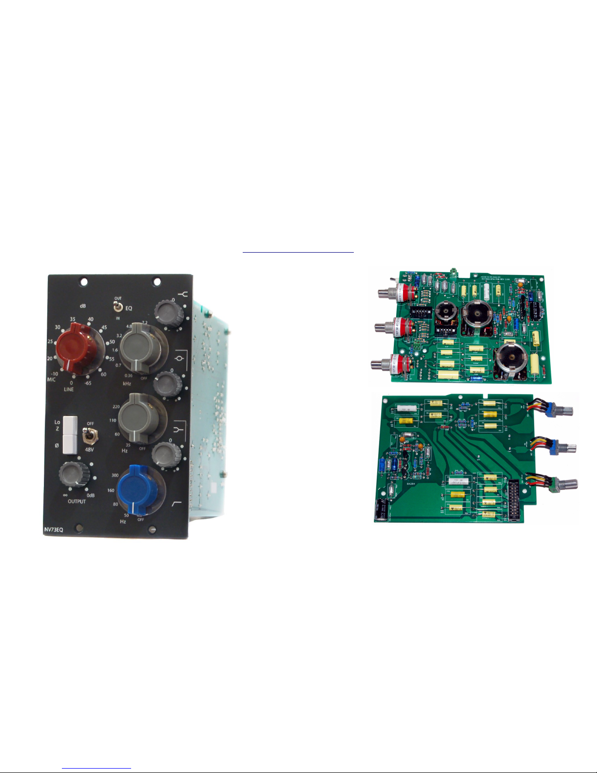
the DON classics
www.thedonclassics.com
NV73EQ
(ADD-ON)
ASSEMBLY GUIDE
REV: 1:00
© the DON classics 2015 page 1 of 20
Page 2

QUICK ASSEMBLY GUIDE
8 STEPS TO EQ HEAVEN!
1. Place/solder parts on PCB
2. Fit rotary switch pins
3. Wire pots
4. Make ribbon cable
5. Wire to NV73 micpre
6. Place PCBs in metal work
7. Initial test
8. Attach knobs
Equalise!
NOTE: This manual assumes that you already have a fully working 'NV73' micpre and are
upgrading it to the 'NV73EQ' with the 'NV73EQ-Add-on'
© the DON classics 2015 page 2 of 20
Page 3

Frequently Asked Questions (FAQ)
Q. What is the difference between the 'NV73EQ' & 'NV73EQ add-on'?
A. The 'NV73EQ' is a 2 space mic-pre & EQ unit.
The 'NV73EQ-Add-on' is for people already with the NV73 mic-pre who want to upgrade it to the 'NV73EQ'
Q. What is included in the addon kit?
A. Everything included on this page is included in the kit from us.
Q. What other orders do I need to make?
A. You need to make 2 other orders as detailed on this page.
Q. Is there a schematic that would be useful?
A. For reference you can download the NV73EQ schematics from the DON classics website. NV73EQ Schematics
PCB designations reference this.
Q. Who can build this?
A. You!
As long as you have patience and are thorough in your work, anyone can build this add-on. There's not a lot to the circuitry
and is quick to complete with very minimal wiring. There's lots of support and information and it is tried and tested.
Q. How close to the original does it sound?
A. Spot on. We have chosen not to do any “new and improved” updates on a circuit that sounds so good. We have chosen the
same parts that was used originally and recommend this. This includes large footprints for the mustard caps / polystyrene caps
which were used in the vintage unit. And the add-on circuit joins to the mic-pre in exactly the same way as the vintage unit.
© the DON classics 2015 page 3 of 20
Page 4

1. Solder parts on PCB
When inserting parts there are 3 resources that will be useful.
A) Silkscreen images (eg. for any hard to read designations)
Silkscreens can be downloaded on the manual page: silkscreens
B) General BOM (eg. For more info on specific parts/values)
General BOM can be found on the manual page: General BOM
C) Schematic (eg. For general confirmation of circuit)
General BOM can be found on the manual page: Schematics
Armed with that info, let's start!
Insert all parts on to the PCB as marked on the silkscreen. All designations and values for parts are marked on the PCB for ease
TIPS:
Start with smaller parts (resistors etc.) and work up to the larger parts
Solder inline sockets for transistors on both EQ boards
Fit bottom parts first on BTM PCB as there'll be less room to solder up top.
Make sure no metal legs protrude too much on the TOP PCB
All the small 1/8W sized resistors near the rotary switches are 4M7 if not stated otherwise.
Green molex K & 24V opening should face the middle rotary switch
Green molex P & 0V opening should face the PCB cutout
The 47pF caps are a hot topic.. some vintage units have them removed, some don't. They exhibit a large drop in the top end when
EQ is pushed in, however if you are trying to emulate a particular vintage unit then the footprint is there. It's up to you!
© the DON classics 2015 page 2 of 20
Page 5
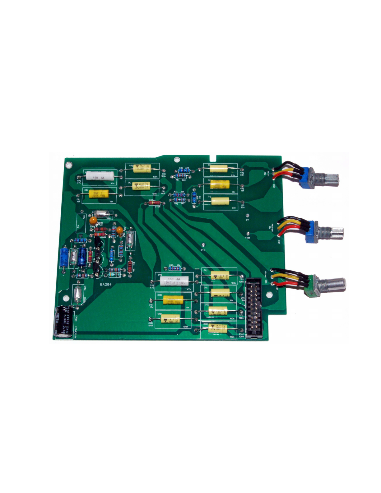
PCBs should end up looking like this...
TOP PCB:
© the DON classics 2015 page 5 of 20
Page 6
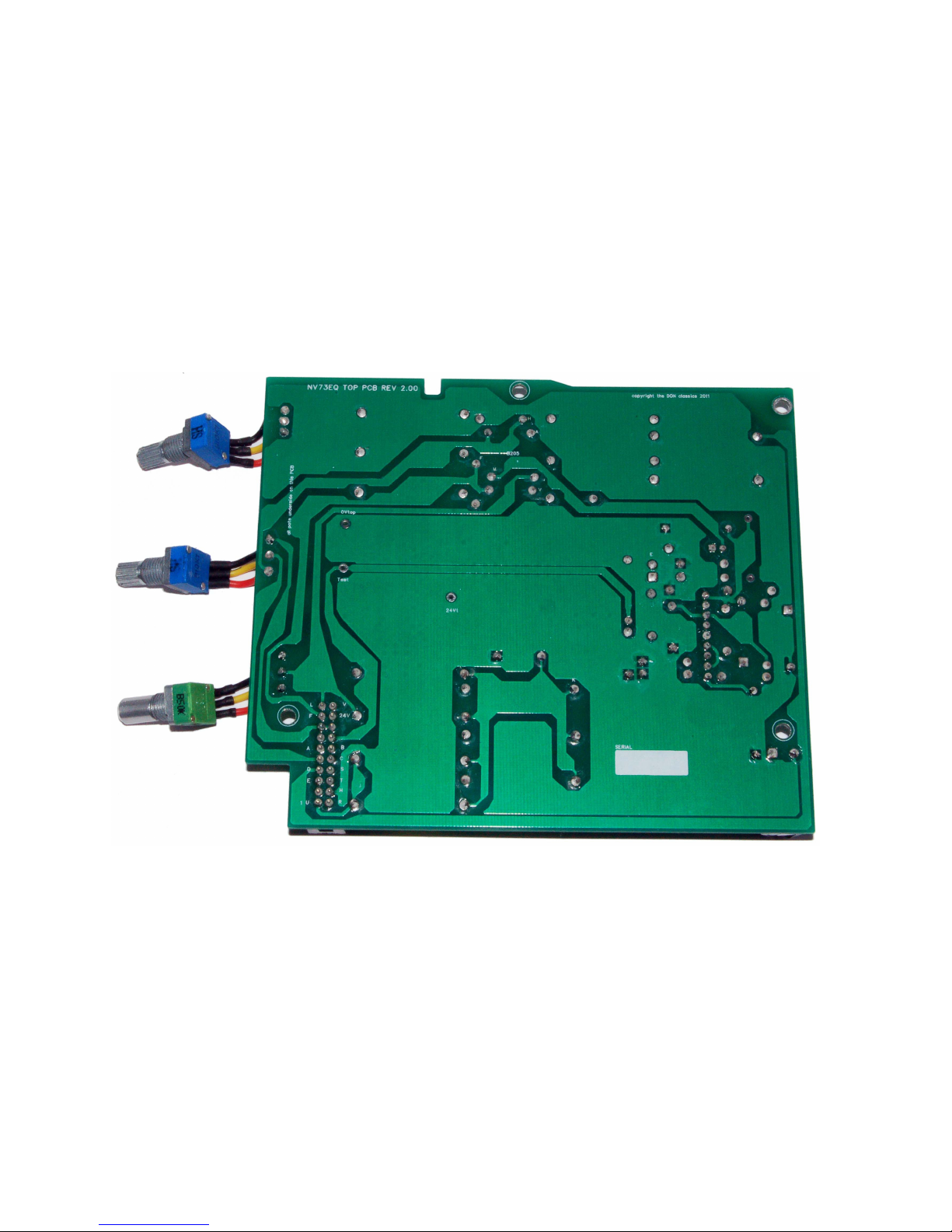
TOP PCB (underside):
© the DON classics 2015 page 2 of 20
Page 7
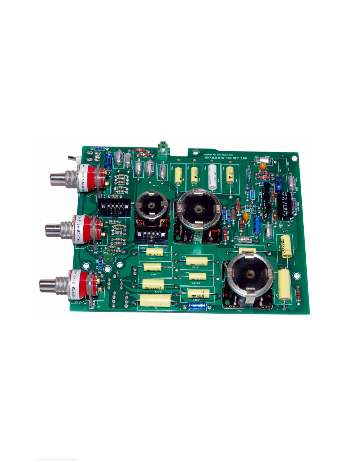
BTM PCB:
© the DON classics 2015 page 7 of 20
Page 8
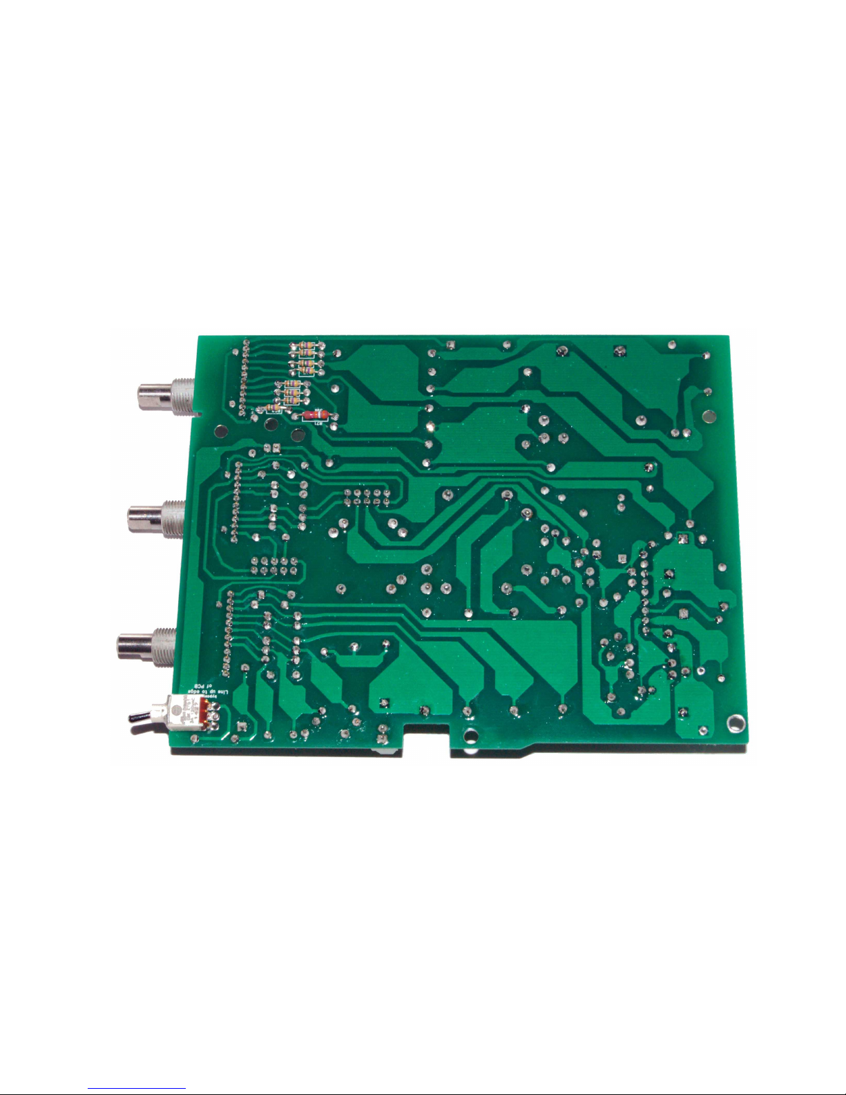
BTM PCB (underside):
© the DON classics 2015 page 2 of 20
Page 9
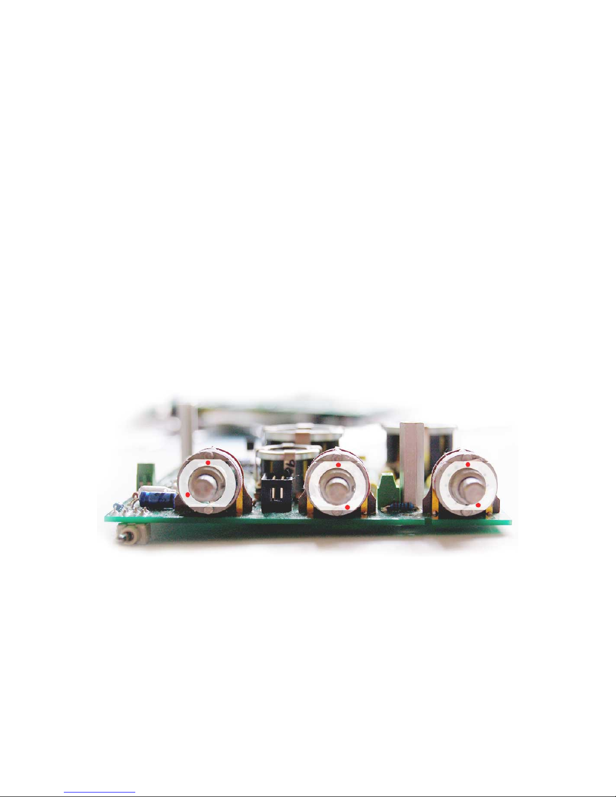
2. Fit rotary switch pins as shown
Before inserting the stopper pins confirm that the common leg shorts to leg 1 of the switch (edge closest the common pin)
If it doesn't, twist the shaft to the position where it does. OR insert the pin in 12 o'clock, and then twist the shaft
anticlockwise all the way. (Either method will work)
Fit the stopper pins in the positions shown (or a bit of component leg if you have misplaced the pins!)
Place the metal sticker over the pins (remove the inner middle circle sticker)
NOTE: For the presence setting (there was an extra position of 10kHz. Achieved simply by an extra cap in an extra switch position.
I've included this cap so you will have the extra position of 10kHz.
If you prefer, you can of course set this rotary switch to just the 7 positions like the 1073 & front panel.
© the DON classics 2015 page 9 of 20
Page 10
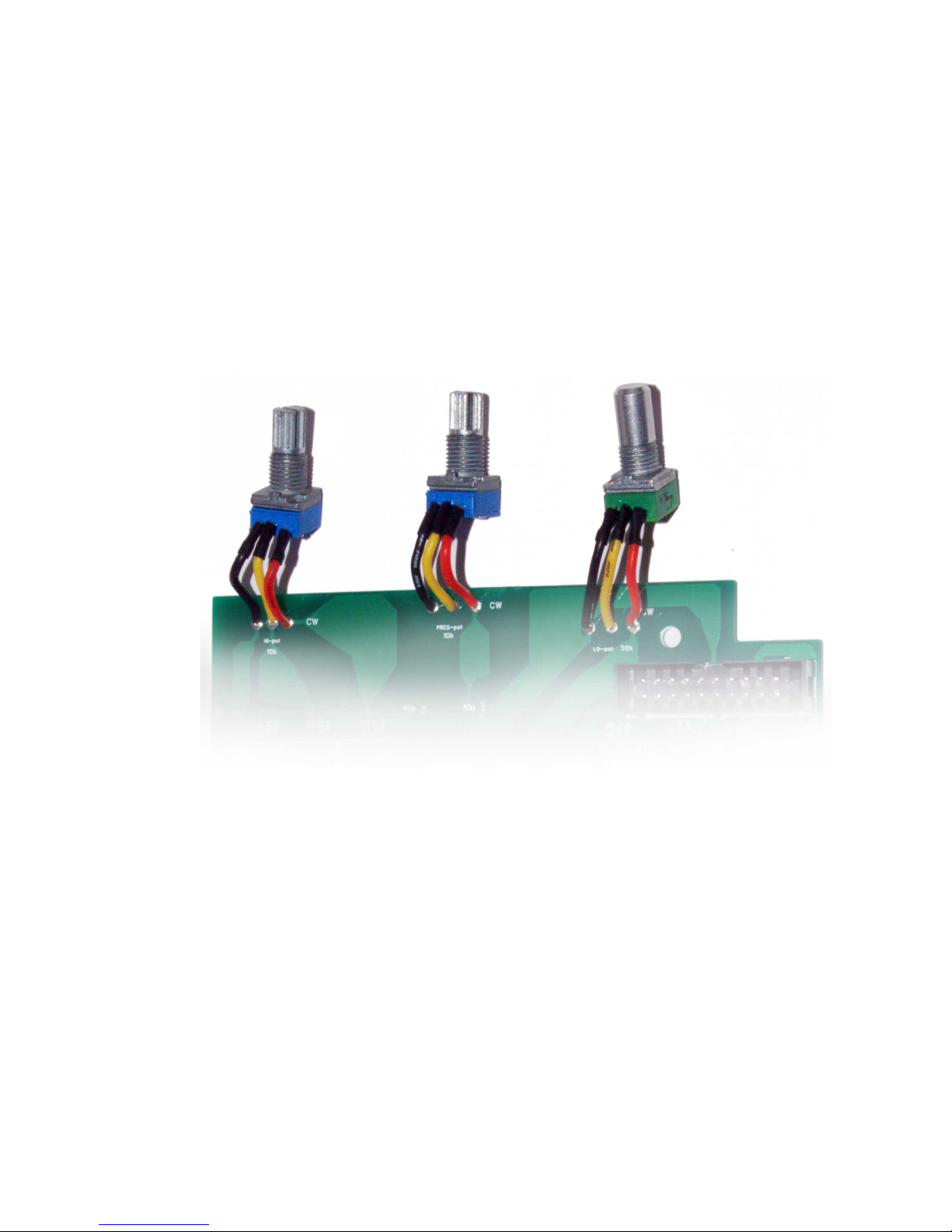
3. Wire the pots
Wire pots as shown:
TIP: A little heatshrink will keep things neat and make sure no shorts happen between connections.
© the DON classics 2015 page 2 of 20
Page 11
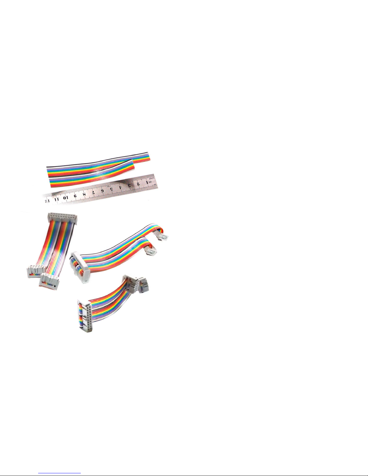
4. Make ribbon cable
Cut the 20way ribbon cable as shown in cm
(using scissors, cut straight and not off angle)
(Split the ribbon cable down the middle along half its length)
Black is pin 1 as shown.
Make sure black will connect to pin 1 of the IDC headers.
(The triangles are pin 1 on the IDC headers.)
Make sure the headers line up as shown.
(Red will be pin 1 if using a grey ribbon cable)
One at a time line up the headers correctly
(straight so the teeth line up & is not crooked)
Push down with fingers until it grips and confirm all is lined up.
Flush or overhanging the edge a little is correct.
Keep applying firm pressure so it doesn't slip out.
Squash in a vice or use a handheld IDC tool.
It will clip into place.
Confirm the 2 side edge teeth pop through.
Once fitted, bend back the ribbon cable and fit strain relief
clips.
Split the cable further long the middle to increase flexibility
when plugging in the PCBs
© the DON classics 2015 page 11 of 20
Page 12

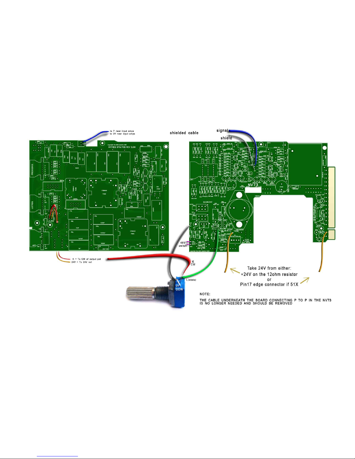
5. Wire to NV73 micpre
Remove the shielded cable on the bottom of the NV73 mic pre PCB.
Remove the CW wire on the output gain potentiometer on the NV73.
Cut and strip a shielded cable as shown for P & 0V.
Cut and strip 2 wires for K & 24V.
Place the BTM PCB roughly in place as a reference for how long the wires should be.
Solder wires as shown.
The K & 24V wires can poke up through the extra hole in the BTM PCB.
The next page shows the connections...
© the DON classics 2015 page 2 of 20
Page 13
© the DON classics 2015 page 13 of 20
Page 14
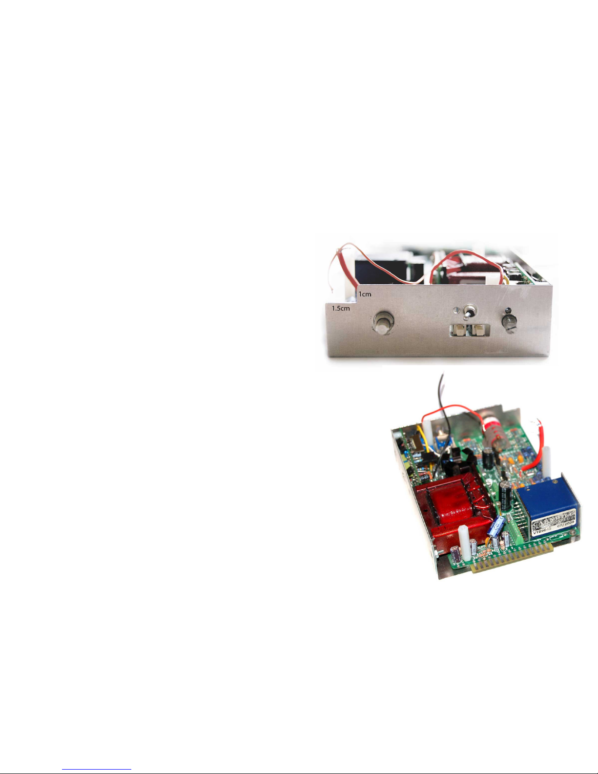
6. Fit metal work
Cut a small section off the corner of the L-bracket to fit the
new EQ bypass switch.
Use aviation snips for less mess.. or a nibbler.. or a
hacksaw/file if you prefer.
It will be hidden by the front panel, so no need to be too precise.
Prepare the L-bracket like before using the countersunk screws
and standoffs.
Place the one metal standoff like before, near the edge
connector fingers pin1.
And the other nylon standoffs like before.
Fit everything in the NV73 like normal. eg. Transformers, Small PSU PCB..
Place in the pot and phantom switch.. use the tabbed washer and make sure they
don't fall back into the unit where it will be difficult to grab once we place on
the other PCBs.
Now the NV73 is together. Secure it in the L-bracket.
For the one metal standoff (near pin 1), use a normal pan head screw like
before.
For the other standoffs, use the 3 large nylon male/female standoffs.
Now confirm the following three things:
1) 2N3055 case should short to output transformer pin 1..
2) Output transformer pins shouldn't short to ground..
3) Terminal block screws are tightened..
© the DON classics 2015 page 2 of 20
Page 15
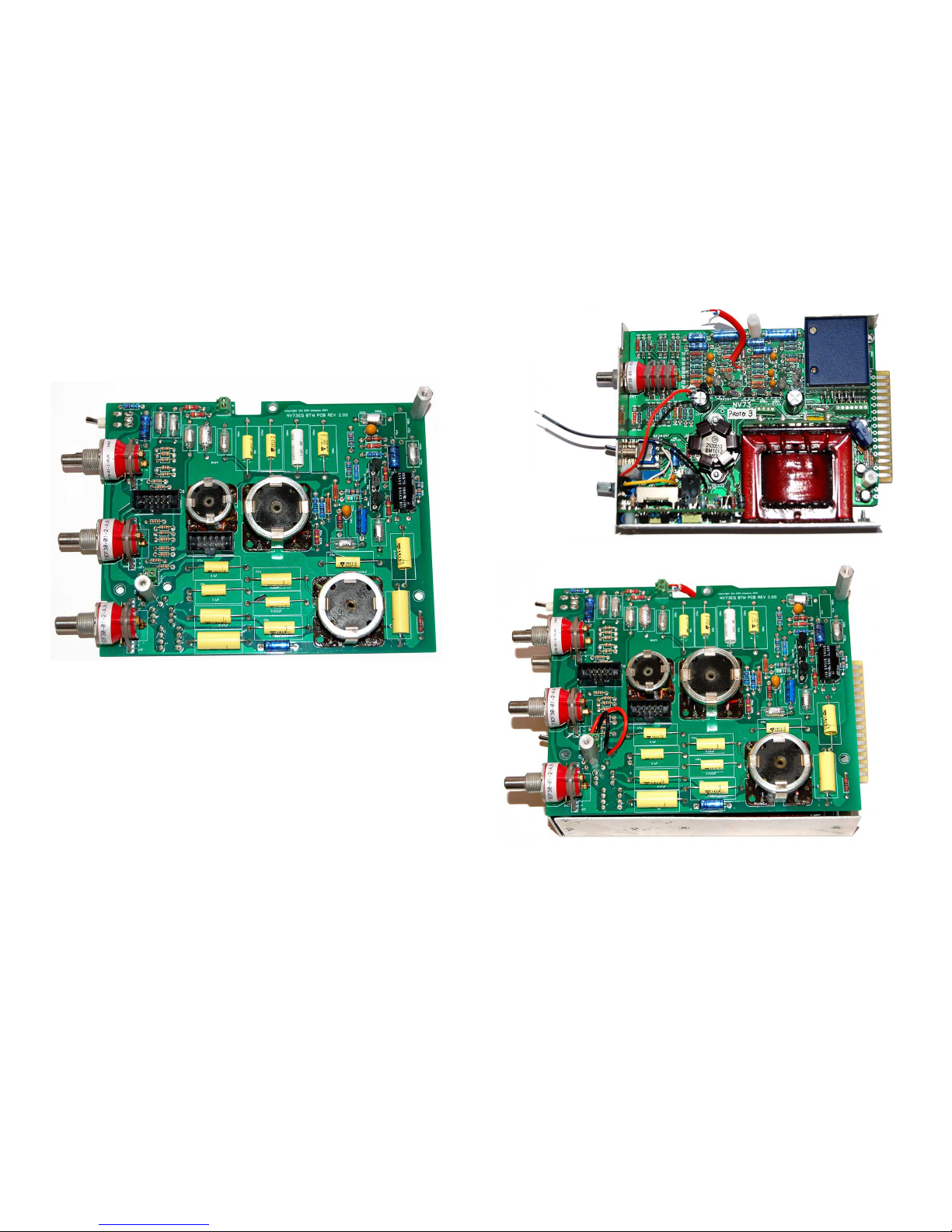
Place two 1inch metal standoff on the BTM PCB as shown below.
Secure with nut.
Place on the BTM PCB and feed through the wires
Tighten the screws in the two green terminal blocks.
© the DON classics 2015 page 15 of 20
Page 16
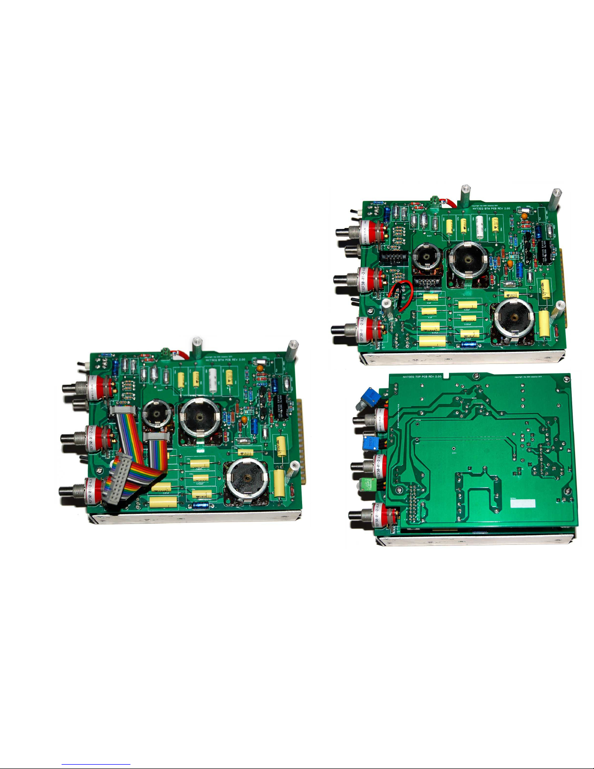
Secure the BTM PCB
Use a small pan head screw for the nylon standoff closest
to the 48V switch.
Use metal 1inch standoffs for the other 2 nylon standoffs.
Insert the ribbon cable into the BTM PCB and TOP PCB.
Carefully shift the ribbon cable until the TOP PCB lines up with
the standoffs and screw using the remaining 4 pan head screws.
© the DON classics 2015 page 2 of 20
Page 17
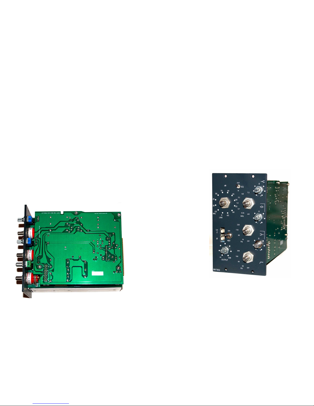
Before placing the front panel it's worth checking that there is no short on the power rails to ground. So confirm there's no
continuity between the 24V and 0V pins marked on the top of the PCB and also the edge connectors voltage rails and
ground. Pins 1,5 & 13 are ground. Pins 12,14,15 are power rails.
(Pins 17 & 18 on 51X are also power rails)
(Power rails shouldn't short to each other or to ground.)
(a small beep when first testing is normal as the caps charge up.)
Insert front panel carefully making sure the pot and 48V switch doesn't fall back into the unit.
Secure everything with nuts.
For the phantom switch you can reach in with a long nosed pliers if needs be to
help when tightening.
Same with the tab on the small pot. If not, long tweezers could also prevent
turning of the body when tightening.
Make use of the blind holes in the front panel for the tabs on the potentiometers.
© the DON classics 2015 page 17 of 20
Page 18

7. Initial test
Turn the unit on!
Once the unit is on, measure to make sure you are reading +24V You can check on the top where +24V is marked and 0V.
Run some audio through the unit with EQ on and off and check that it sounds good and all controls work correctly.
Make sure there is no buzz or hum from the unit.
If all is well then we can fit the knobs...
© the DON classics 2015 page 2 of 20
Page 19
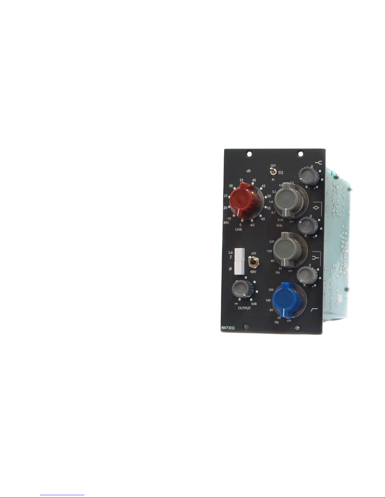
8. Attach knobs
Allow a little distance between the knobs and the front panel so the
knobs don't grib against the front panel.
Use a small flat head screw driver. (Use two at the same time for an
easier way to secure the knobs evenly.
Use a T2 sized head screw the small grey knobs on.
Congratulations! Get recording & mixing!
© the DON classics 2015 page 19 of 20
Page 20
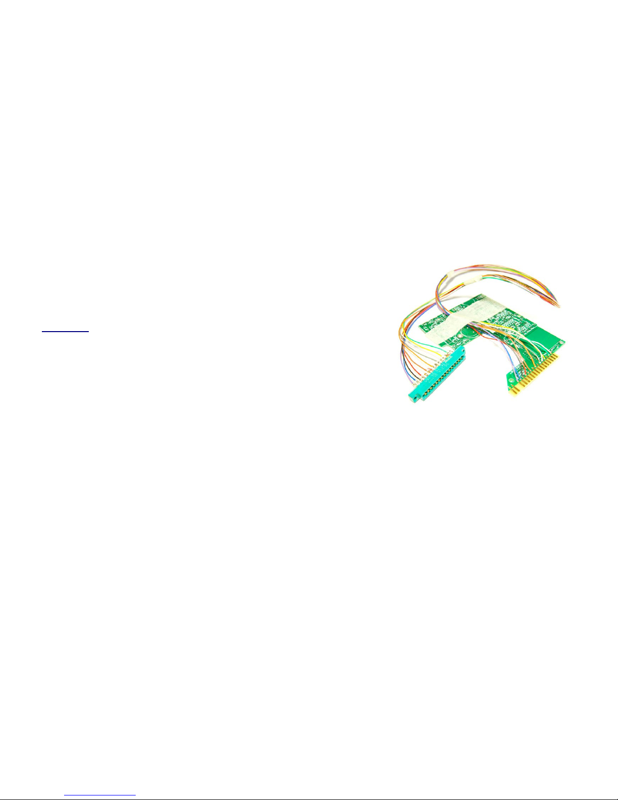
* Further troubleshooting
For more in depth troubleshooting tests, it may be worthwhile to build or buy a little
jig to test units without having to root around in a lunchbox. eg. An EDAC attached
to long wires attached to a PCB with the 15/18 gold fingers to insert to the lunchbox.
(One source of card edge connectors and edge adapters is Jeff's excellent store
classicAPI)
© the DON classics 2015 page 2 of 20
 Loading...