

Page 1

Thecus
N3200XXX/N0503
N4100PRO
N4200 series
N5200XXX/N5500
1U4200XXX/1U4600
N7700 series
N2200XXX
N8200XXX/N8800 series
N8900
User’s Manual
Page 2

2
Copyright and Trademark Notice
Thecus and other names of Thecus products are registered trademarks of Thecus
Technology Corp. Microsoft, Windows, and the Windows logo are registered
trademarks of Microsoft Corporation. Apple, iTunes and Apple OS X are registered
trademarks of Apple Computers, Inc. All other trademarks and brand names are the
property of their respective owners. Specifications are subject to change without
notice.
Copyright © 2011 Thecus Technology Corporation. All rights reserved.
About This Manual
All information in this manual has been carefully verified to ensure its correctness.
In case of an error, please provide us with your feedback. Thecus Technology
Corporation reserves the right to modify the contents of this manual without notice.
Product name:
Thecus N2200XXX/N3200XXX/N0503/N4100PRO/N4200 series
/N5200XXX/N5500/1U4200XXX/1U4600/N7700 series/N8800
series/N8200XXX/N8900
Manual Version: 6.3
Release Date: May 2011
Limited Warranty
Thecus Technology Corporation guarantees all components of Thecus NAS products
are thoroughly tested before they leave the factory and should function normally
under general usage. In case of any system malfunctions, Thecus Technology
Corporation and its local representatives and dealers are responsible for repair
without cost to the customer if the product fails within the warranty period and
under normal usage. Thecus Technology Corporation is not responsible for any
damage or loss of data deemed to be caused by its products. It is highly
recommended that users conduct necessary back-up practices.
Page 3

3
Safety Warnings
For your safety, please read and follow the following safety warnings:
Read this manual thoroughly before attempting to set up your Thecus IP
storage.
Your Thecus IP storage is a complicated electronic device. DO NOT attempt
to repair it under any circumstances. In the case of malfunction, turn off the
power immediately and have it repaired at a qualified service center. Contact
your vendor for details.
DO NOT allow anything to rest on the power cord and DO NOT place the
power cord in an area where it can be stepped on. Carefully place connecting
cables to avoid stepping or tripping on them.
Your Thecus IP storage can operate normally under temperatures between
5°C and 40°C, with relative humidity of 20% – 85%. Using Thecus IP storage
under extreme environmental conditions could damage the unit.
Ensure that the Thecus IP storage is provided with the correct supply voltage
(AC 100V ~ 240V, 50/60 Hz). Plugging the Thecus IP storage to an incorrect
power source could damage the unit.
Do NOT expose Thecus IP storage to dampness, dust, or corrosive liquids.
Do NOT place Thecus IP storage on any uneven surfaces.
DO NOT place Thecus IP storage in direct sunlight or expose it to other heat
sources.
DO NOT use chemicals or aerosols to clean Thecus IP storage. Unplug the
power cord and all connected cables before cleaning.
DO NOT place any objects on the Thecus IP storage or obstruct its ventilation
slots to avoid overheating the unit.
Keep packaging out of the reach of children.
If disposing of the device, please follow your local regulations for the safe
disposal of electronic products to protect the environment.
Page 4

4
Table of Contents
Copyright and Trademark Notice ................................................. 2
About This Manual....................................................................... 2
Limited Warranty ........................................................................ 2
Safety Warnings.......................................................................... 3
Table of Contents ........................................................................ 4
Chapter 1: Introduction............................................................... 7
Overview ...............................................................................................7
Product Highlights.................................................................................7
Package Contents..................................................................................9
Front Panel..........................................................................................10
Hard Disk Trays ...................................................................................21
Rear Panel...........................................................................................24
Chapter 2: Hardware Installation .............................................. 36
Overview .............................................................................................36
Before You Begin.................................................................................36
Cable Connections ...............................................................................36
Checking System Status ................................................................ 38
System Status Normal................................................................... 38
System Trouble ............................................................................ 38
Chapter 3: First Time Setup....................................................... 45
Overview .............................................................................................45
Thecus Setup Wizard...........................................................................45
LCD Operation
(N4100PRO/N5200XXX/N5500/1U4200XXX/1U4600/N7700
series/N8200XXX/N8800 series) ........................................................47
LCD Operation (N3200XXX/N0503).....................................................49
OLED Operation (N4200 series/N8900) ..............................................50
Typical Setup Procedure ......................................................................51
Chapter 4: System Administration ............................................. 53
Overview .............................................................................................53
Web Administration Interface .............................................................53
My Favorite.................................................................................. 54
Menu Bar..................................................................................... 56
Message Bar ................................................................................ 57
System Information.............................................................................58
General Information...................................................................... 58
System/Service Status .................................................................. 58
Logs............................................................................................60
On-line Register ........................................................................... 61
Syslog Management...................................................................... 62
System Management ...........................................................................62
Date and Time: System Date and settings ....................................... 63
Notification configuration ............................................................... 64
Firmware Upgrade ........................................................................ 65
Schedule Power On/Off.................................................................. 65
Administrator password................................................................. 66
Config Mgmt ................................................................................ 67
Factory default ............................................................................. 68
Reboot & Shutdown ...................................................................... 68
Page 5

5
File System check......................................................................... 68
Wake-Up On LAN (WOL) ................................................................ 70
SNMP Support.............................................................................. 70
UI Login Configuration................................................................... 71
System Network ..................................................................................71
WAN/LAN1................................................................................... 71
LAN2........................................................................................... 73
DHCP Server Configuration ............................................................ 74
LAN3(For the N8900) .................................................................... 74
DHCP Server Configuration(For the N8900)...................................... 75
Storage Management...........................................................................75
Disks Information ......................................................................... 75
RAID Information.......................................................................... 78
Space Allocation ........................................................................... 88
iSCSI Thin-Provisioning ................................................................. 93
Advance Option ............................................................................ 97
iSCSI(For the N8900).................................................................... 98
iSCSI Thin-Provisioning(For the N8900)......................................... 103
LUN ACL(For the N8900) ............................................................. 104
Advance Option(For the N8900) ................................................... 106
Stackable NAS(Does not apply to the N8900)................................. 107
ISO Mount ................................................................................. 113
Share Folder .............................................................................. 116
Folder and sub-folders Access Control List (ACL) .......................................121
User and Group Authentication..........................................................124
ADS/NT Support......................................................................... 124
Local User Configuration .............................................................. 126
Local Group Configuration............................................................ 128
Batch Create Users and Groups .................................................... 130
Quota........................................................................................ 131
Network Service ................................................................................132
Samba / CIFS............................................................................. 132
AFP (Apple Network Setup).......................................................... 133
NFS Setup ................................................................................. 134
FTP ........................................................................................... 134
TFTP ......................................................................................... 135
HTTP/ Web Disk.......................................................................... 136
UPnP......................................................................................... 137
Bonjour Setting .......................................................................... 137
Application Server .............................................................................137
iTunes® Server.......................................................................... 137
Module Installation...................................................................... 138
Auto Module Installation .............................................................. 138
Backup ..............................................................................................140
Nsync (Does not apply to the 3x series) ........................................ 140
Nsync Target (Does not apply to the 3X series) .............................. 142
Dual DOM (Not available on N3200XXX/N0503/N4200Eco/N7700/N8800
NAS) ..................................................................................................... 143
Rsync Target (For the 3x series/N8900) ........................................ 143
Rsync (For 3x series/N8900)........................................................ 144
Thecus Backup Utility .................................................................. 146
Windows XP Data Backup ............................................................ 147
Apple OS X Backup Utilities.......................................................... 148
External Device..................................................................................148
Printer Information ..................................................................... 148
UPS Setting ............................................................................... 153
Chapter 5: Using Thecus IP Storage......................................... 154
Page 6

6
Overview ...........................................................................................154
Login Page.........................................................................................154
Using the Web Disk (Does not apply to the 3X series’ Web Disk) ......154
Photo Server (Does not apply to the 3X series’ photo server) ...........157
Windows XP Publishing Wizard ..................................................... 157
Managing Albums and Photos....................................................... 162
Creating Albums......................................................................... 163
Password Protecting Albums......................................................... 163
Uploading Pictures to Albums ....................................................... 163
EXIF Information ........................................................................ 164
Slide Shows ............................................................................... 164
Mapping a Client PC to the Thecus IP Storage ...................................165
Windows.................................................................................... 165
Apple OS X ................................................................................ 165
Mapping Thecus IP storage as an iSCSI Drive....................................165
Windows 2000/XP....................................................................... 166
Windows Vista............................................................................ 170
Chapter 6: Tips and Tricks....................................................... 170
USB and eSATA Storage Expansion....................................................170
Adding a Spare Disk ..........................................................................170
Remote Administration ......................................................................170
Part I - Setup a DynDNS Account.................................................. 171
Part II - Enable DDNS on the Router ............................................. 171
Part III - Setting up Virtual Servers (HTTPS) .................................. 171
Firewall Software Configuration ........................................................171
Replacing Damaged Hard Drives........................................................172
Hard Drive Damage .................................................................... 172
Replacing a Hard Drive ................................................................ 172
RAID Auto-Rebuild...................................................................... 172
Chapter 7: Troubleshooting ..................................................... 173
Forgot My Network IP Address..........................................................173
Can't Map a Network Drive in Windows XP........................................173
Restoring Factory Defaults ................................................................173
Problems with Time and Date Settings..............................................174
Dual DOM Supports for Dual Protection .............................................174
Appendix A: Customer Support................................................ 175
Appendix B: RAID Basics......................................................... 176
Overview ...........................................................................................176
Benefits .............................................................................................176
Improved Performance ................................................................ 176
Data Security ............................................................................. 176
RAID Levels.......................................................................................176
Appendix C: Active Directory Basics......................................... 179
Overview ...........................................................................................179
What is Active Directory? ..................................................................179
ADS Benefits......................................................................................179
Appendix D: Licensing Information.......................................... 180
Overview ...........................................................................................180
Source Code Availability ....................................................................180
CGIC License Terms...........................................................................181
GNU General Public License...............................................................181
Page 7

7
Chapter 1: Introduction
Overview
Thank you for choosing the Thecus IP Storage Server. The Thecus IP storage is an
easy-to-use storage server that allows a dedicated approach to storing and
distributing data on a network. Data reliability is ensured with RAID features that
provide data security and recovery—over multiple Terabyte of storage are available
using RAID 5 and RAID 6 (depending on model). Gigabit Ethernet ports enhance
network efficiency, allowing Thecus IP storage to take over file management
functions, increase application and data sharing and provide faster data response.
The Thecus IP storage offers data mobility with a disk roaming feature that lets you
swap working hard drives for use in other Thecus IP storage, securing the continuity
of data in the event of hardware failure. The Thecus IP storage allows data
consolidation and sharing between Windows (SMB/CIFS), UNIX/Linux, and Apple
OS X environments. The Thecus IP storage’s user-friendly GUI supports multiple
Languages.
Product Highlights
File Server
First and foremost, the Thecus IP storage allows you to store and share files over an
IP network. With a Network Attached Storage (NAS) device, you can centralize your
files and share them easily over your network. With the easy-to-use web-based
interface, users on your network can access these files in a snap.
To learn about the Web User Interface, go to
Chapter 5: Using the Thecus IP Storage > Using WebDisk.
FTP Server
With the built-in FTP Server, friends, clients, and customers can upload and
download files to your Thecus IP storage over the Internet with their favorite FTP
programs. You can create user accounts so that only authorized users have access.
To set up the FTP Server, refer to
Chapter 4: System Administration>Network service> FTP .
iTunes Server
With the built-in iTunes server capability, the Thecus IP storage enables digital
music to be shared and played anywhere on the network!
To set up the iTunes Server, refer to
Chapter 4: Application Server>iTunes Configuration.
Backup Server
Don’t leave precious data to chance. With advanced backup capabilities, you can
easily upload mission critical files to the Thecus IP storage, and even automate your
backup tasks for true peace-of-mind.
To find out how to backup your files with the Thecus IP storage, refer to
Chapter 4: Backup > Nsync. (Does not apply to the 3x series)
Page 8

8
Printer Server
With the Thecus IP storage’s Printer Server, you can easily share an IPP printer with
other PCs connected to your network.
To set up the Printer Server, refer to
Chapter 4: External Device>Printer Information.
Multiple RAID
Thecus IP storage supports multiple RAID volumes on one system. So, you can
create RAID 0 for your non-critical data, and create RAID 1,5 or 6 (depend on model)
for mission-critical data. Create the RAID levels depending on your needs.
To configure RAID modes on the Thecus IP storage, refer to
Chapter 4: Storage Management >RAID Information.
iSCSI Capability
Thecus IP storage is not only a file server, but it also supports iSCSI initiators. Your
server can access Thecus IP storage as a direct-attached-storage over the LAN or
Internet. There is no easier way to expand the capacity of your current application
servers. All the storage needs can be centrally managed and deployed. This brings
ultimate flexibility to users.
To set up an iSCSI volume, refer to
Chapter 4: Storage Management > Space Allocation > Allocating Space for
iSCSI Volume.
Superior Power Management
Thecus IP storage supports schedule power on/off. With this feature, administrator
can set at what time to turn on or off the system. This feature is a big plus for people
who want to conserve energy. Wake-On-LAN enables administrator to remotely turn
on the system without even leaving their own seat.
To schedule system on and off, refer to
Chapter 4: System Management> Scheduled Power On/Off
Page 9

9
Package Contents
The Thecus IP storage should contain the following common items:
System Unit x1
QIG (Quick Installation Guide) x1
CD-Title x3 (Acronics backup CD , Twonky media server CD & Universal CD)
Ethernet Cable x1
Accessory bag x1
HDD Compatibility list Card x1
Multiple Languages Warranty Card x1
Power cord x1
Your N3200XXX package should contain additional items:
3.5” HDD rail x6
Power Adaptor + Power cord x1
Your N0503 package should contain additional items:
3 to 5 HDD cage x1 (Installed)
3.5” HDD rail x6
Power Adaptor + Power cord x1
Your N4200 series package should contain additional items:
Power adapter + Power cordx1
Your N5500 package should contain additional items:
USB Cable (A-B Type) x1
Your 1U4200XXX package should contain additional items:
Power Cord
1U4200XXXRx1
Your 1U4600 package should contain additional items:
Power Cord
1U4600Rx1
USB Cable (A-B Type) x1
Your N8800/N8200XXX series package should contain additional items:
Power Cord x1
Please check to see if your package is complete. If you find that some items are
missing, contact your dealer.
Page 10

10
Front Panel
N2200XXX:
The Thecus N2200XXX’s front panel has the device’s controls, indicators, and hard
disk trays:
Front Panel
Item Description
1. Power Button Powers the N2200XXX on/off.
2. USB Port USB 2.0 port for compatible USB devices, such as digital cameras,
USB disks, and USB printers.
3. USB Copy
Button
Copies USB storage contents to N2200XXX.
4. Card reader Supports SD/SDHC/MMC cards via USB interface.
5. HDD1 led Blinking white: HDD activity
6. HDD2 led Blinking white: HDD activity
7. WAN led Solid white: WAN Cable link
Blinking white: Network activity
8. LAN led Solid white: LAN Cable link
Blinking : Network activity
9. USB Copy led Blinking white: USB copy activity
10. Card reader
led
Blinking white: Card reader copy activity
Page 11
11
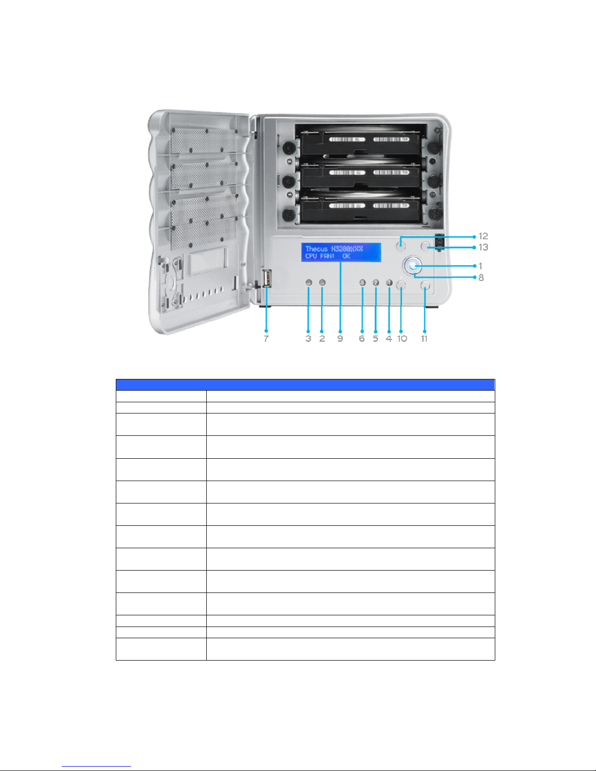
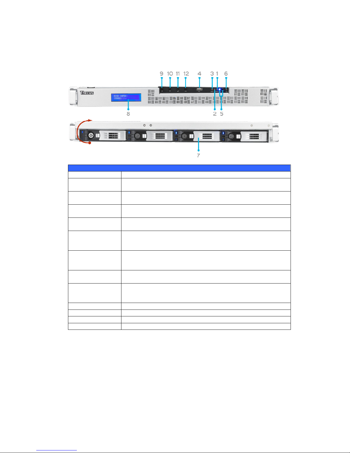
N3200XXX:
The Thecus N3200XXX’s front panel has the device’s controls, indicators, and hard
disk trays:
Front Panel
Item Description
1. Power LED Solid blue: System is powered on
2. WAN/LAN1 LED Solid green: Network link
Blinking orange: Network activity
3. LAN2 LED Solid green: Network link
Blinking orange: Network activity
4. HDD 1 LED Solid red: HDD failed
Blinking orange: HDD activity
5. HDD 2 LED Solid red: HDD failed
Blinking orange: HDD activity
6. HDD 3 LED Solid red: HDD failed
Blinking orange: HDD activity
7. USB Port USB 2.0 port for compatible USB devices, such as digital cameras,
USB disks, and USB printers.
8. Power Button Powers the N3200XXX on/off.
Solid blue: Device is powered on
9. LCD Display Displays current system status and messages (Update time: 60
seconds).
10. Down Button ▼ Push to scroll DOWN when using the LCD display.
11. Up Button ▲ Push to scroll UP when using the LCD display.
12. Enter Button Push to confirm information entered into the LCD display.
13. Escape Button
ESC
Push to leave the current LCD menu.
Page 12
12
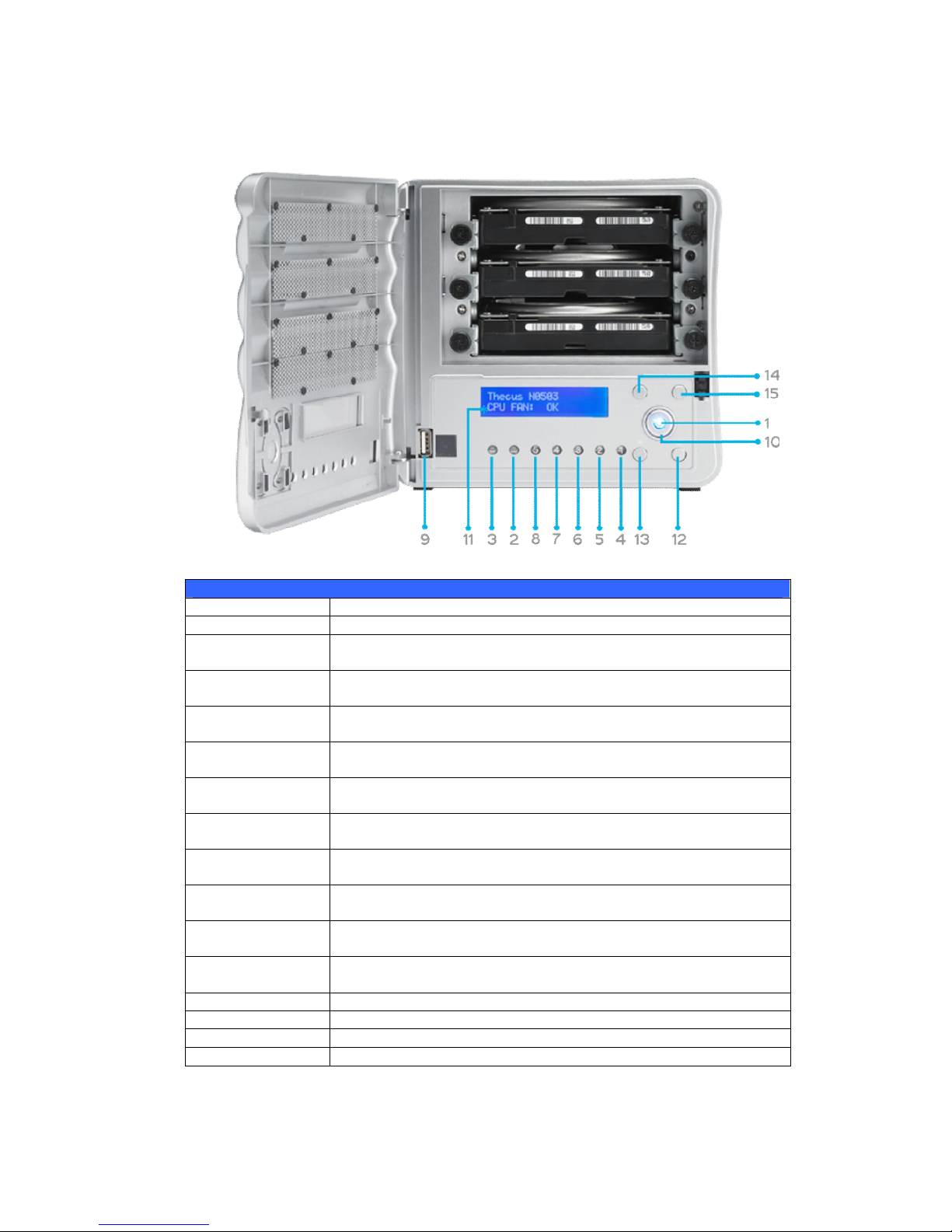
N0503:
The Thecus N0503’s front panel has the device’s controls, indicators, and hard disk
trays:
Front Panel
Item Description
Power LED Solid blue: System is powered on
WAN/LAN1 LED
Solid green: Network link
Blinking orange: Network activity
LAN2 LED
Solid green: Network link
Blinking orange: Network activity
HDD 1 LED Solid red: HDD failed
Blinking orange: HDD activity
HDD 2 LED Solid red: HDD failed
Blinking orange: HDD activity
HDD 3 LED Solid red: HDD failed
Blinking orange: HDD activity
HDD 4 LED Solid red: HDD failed
Blinking orange: HDD activity
HDD 5 LED Solid red: HDD failed
Blinking orange: HDD activity
USB Port
USB 2.0 port for compatible USB devices, such as digital cameras,
USB disks, and USB printers.
Power Button Powers the N0503 on/off.
Solid blue: Device is powered on
LCD Display Displays current system status and messages (Update time: 60
seconds).
Down Button ▼ Push to scroll DOWN when using the LCD display.
Up Button ▲ Push to scroll UP when using the LCD display.
Enter Button Push to confirm information entered into the LCD display.
Escape Button ESC Push to leave the current LCD menu.
Page 13

13
N4100PRO
The N4100PRO’s front panel displays the unit’s array of status LED’s and is also
where you’ll find the power buttons. See the table below for a detailed explanation
of each:
Item Description
HDD Trays There are four hard disk drive (HDD) trays. Each tray supports
a 3.5-inch SATA HDD. The trays have locks for added physical
security and keys are provided with the package.
Power LED Solid blue: N4100PRO is powered on
Busy LED Blinking orange: system startup or maintenance; data
inaccessible
Off: system startup complete; system operating normally
WAN LED
Solid green: network link
Blinking green: network activity
LAN LED
Solid green: network link
Blinking green: network activity
Error LED Solid red: system error detected
Power Button Power on/off N4100PRO
Page 14

14
N4200 series:
The Thecus N4200series front panel has the device’s controls, indicators, and hard
disk trays:
Front Panel
Item Description
Power Button Power on/off N4200series
OLED Displays current system status and messages
OLED screen saver will be enabled after screen is left idle for more
than 3 mins
OLED screen will be diabled after it is left idle for more than 6 mins
HDD 1 LED Yellow: HDD activity
Red: HDD failure
HDD 2 LED Yellow: HDD activity
Red: HDD failure
HDD 3 LED Yellow: HDD activity
Red: HDD failure
HDD 4 LED Yellow: HDD activity
Red: HDD failure
WAN/LAN1
LED
Blinking green: network activity
LAN2 LED Blinking green: network activity
OLED
USB Copy ● Blue: USB Copy activity
● Red: USB Copy failure
HDD Tray Four HDD trays support 4x 3.5" or 4 x 2.5” HDDs
USB Copy Button Copies USB storage contents to the N4200 series.
USB Port USB 2.0 port for compatible USB devices, such as USB disks.
Page 15
15
N5200XXX/N5500:
The Thecus N5500 front panel has the device’s controls, indicators, and hard disk
trays:
Front Panel
Item Description
1.System LED Blinking orange: System is being upgraded or ;is starting up;
data currently inaccessible
2.WAN/LAN1 LED
Solid green: Network link
Blinking green: Network activity
3.LAN2 LED
Solid green: Network link
Blinking green: Network activity
4.USB Copy LED Solid blue: Files are being copied from a USB storage device
5.Syetem Warning LED Solid RED: System error
6.Reset Button Resets system configuration to default value.
7.USB Port USB 2.0 port for compatible USB devices, such as USB disks.
8.Power Button/ Power
LED
Power on/off N5200XXX/N5500 and Power LED.
Solid blue: System is power on.
9.Up Button ▲ Push to scroll up when using the LCD display.
10.Down Button ▼ Push to enter the USB copy operation screen.
11.Enter Button Push to enter LCD administrator password to access basic
system setting.
12.Escape Button ESC Push to leave the current LCD menu.
13.LCD Display Displays current system status and warning messages.
14.HDD Trays Five 3.5” SATA HDD trays.
Locks are provided for added security.
Page 16
16
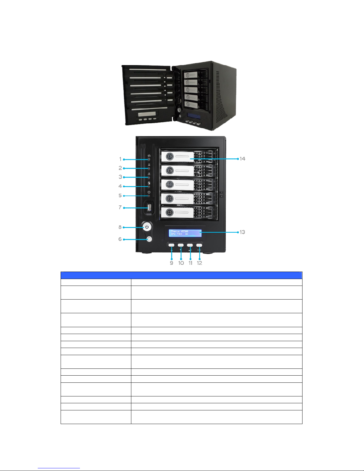
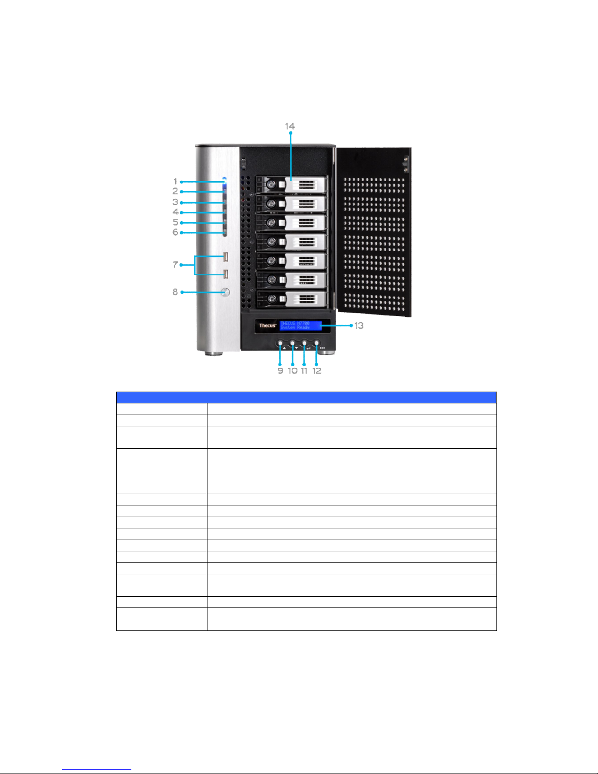
N7700 Series:
The Thecus N7700 series front panel has the device’s controls, indicators, and hard
disk trays:
Front Panel
Item Description
1.Power LED Solid blue: System is power on.
2.System LED Solid orange: system is being upgraded or system startup; data
currently inaccessible
3.WAN/LAN1 LED Solid green: network link
Blinking green: network activity
4.LAN2 LED
Solid green: network link
Blinking green: network activity
5.USB Copy LED Solid blue: files are being copied from a USB storage device
6.eSATA link LED Solid blue: external eSATA device has connected
7.USB Port USB 2.0 port for compatible USB devices, such as USB disks.
8.Power Button Power on/off N7700
9.Up Button ▲ Push to scroll up when using the LCD display
10.Down Button ▼ Push to enter USB copy operation screen
11.Enter Button Push to enter LCD operate password for basic system setting
12.Escape Button
ESC
Push to leave the current LCD menu
13.LCD Display Displays current system status and warning messages
14.HDD Trays Seven 3.5” SATA HDD trays
Locks are provided for added security
Page 17

17
1U4200XXX:
The Thecus 1U4200XXX front panel has the device’s controls, indicators, and
hard disk trays:
Front Panel
Item Description
1. LCD Display Displays the current system status and warning messages.
Displays hostname, WAN/LAN1/LAN2 IP addresses, RAID status,
and current time.
2. Up Button ▲ Push to scroll up when using the LCD display.
3. Down Button ▼ Push to scroll down when using the LCD display.
4. Enter Button Push to confirm information entered into the LCD display.
5. Escape Button
ESC
Push to leave the current LCD menu.
6. Locator Button Turns on the LED backlight.
7. USB Port USB 2.0 port for compatible USB devices, such as digital cameras,
USB disks, and USB printers.
8. PWR LED Solid Blue: System is powered on.
9. Busy LED Blinking orange: system startup or system maintenance; data
currently inaccessible
10. Error LED
Solid Red: System alert: Redundant power or system fan failure
11. LAN LED Solid green: network link
Blinking green: network activity
12. Power Button Power the 1U4200XXX on/off.
13. Reset Button Resets the 1U4200XXX.
14. Mute Button Mutes the system fan alarm (Can also be managed through the UI)
15. HDD Trays Four 3.5” SATA HDD trays.
Locks are provided for added security.
Page 18
18
1U4600:
The Thecus 1U4600 front panel has the device’s controls, indicators, and hard disk
trays:
Front Panel
Item Description
WAN/LAN1 LED
Solid green: network link
Blinking green: network activity
LAN2 LED
Solid green: network link
Blinking green: network activity
Busy LED Blinking orange: system startup or system maintenance; data
currently inaccessible
USB Port
USB 2.0 port for compatible USB devices, such as digital cameras,
USB disks, and USB printers
Power Button Power on/off 1U4600
Solid blue: Device is powered on
Blinking blue: eSATA hard disk is connected and active
Reset Button
Resets the 1U4600
Press for five seconds during boot process to reset IP address and
admin password
HDD Trays Four 3.5” SATA HDD trays
Locks are provided for added security
LCD Display Displays current system status and warning messages
Displays hostname, WAN/LAN1/LAN2 IP address, RAID status, and
current time
Up Button ▲ Push to scroll up when using the LCD display
Down Button ▼ Push to scroll down when using the LCD display
Enter Button Push to confirm information entered into the LCD display
Escape Button ESC Push to leave the current LCD menu
Page 19

19
N8200XXX/N8800 series:
The Thecus N8200XXX/N8800 series front panel has the device’s controls,
indicators, and hard disk trays:
Front Panel
Item Description
1.Power Button Power on/off N8200XXX/N8800
2.Power LED Solid green: System is power on.
3.Reboot Button Press to system reboot
4.System fan alarm
LED
Solid red: system fan failure notification
5. Mute button Mute the system fan alarm.
6.USB Port
USB 2.0 port for compatible USB devices, such as USB disks, USB
printers
7.Up Button ▲ Push to scroll up when using the LCD display
8.Down Button ▼ Push to enter USB copy operation screen
9.Enter Button Push to enter LCD operate password for basic system setting
10.Escape Button
ESC
Push to leave the current LCD menu
Page 20

20
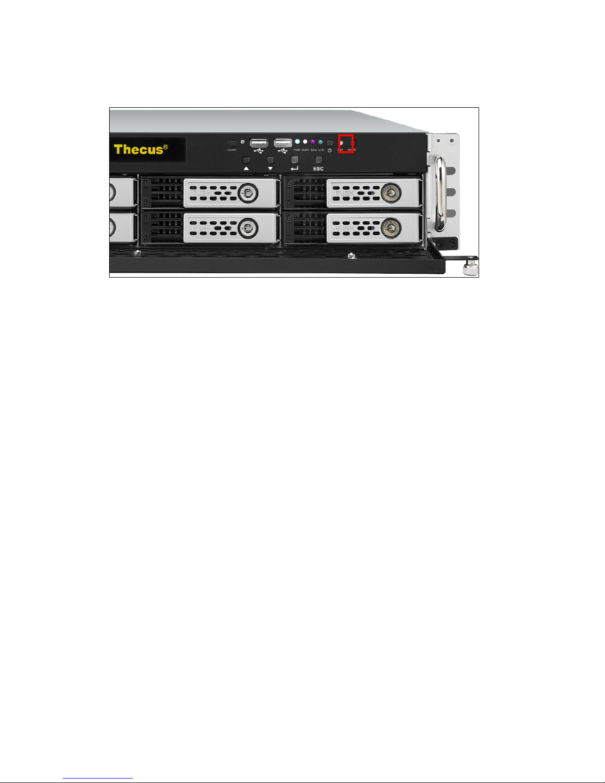
N8900
Front Panel
Item Description
1.Power Button Power on/off N8900
2.Power LED Solid green: System is power on.
3.System error LED Solid RED: System error.
4.Mute button Mute the system fan alarm.
5.USB Port
USB 2.0 port for compatible USB devices, such as USB disks and
USB printers
6. Locator button /
LED
Press the button, the back led will light up to identify the system
position of the rack
7. RST Reboot system.
8. LAN Blinking green: network activity
Solid green: network link
9. BUSY Blinking orange: system startup or system maintenance; data
currently inaccessible
10.OLED Displays current system status and messages
OLED screen saver will be enabled after screen is idle for more
than 3 minutes
OLED screen will be turn off after idle for more than 6 minutes
11.Up Button ▲ Push to scroll up when using the OLED display
12.Down Button ▼ Push to enter USB copy operation screen
13.Enter Button Push to enter OLED operate password for basic system setting
14.Escape Button
ESC
Push to leave the current OLED menu
Page 21

21
Hard Disk Trays
1U4200XXX/N2200XXX/N8200XXX/N8900:
Each of above mentioned models’ hard disk trays has a lock, a latch, and two LED
indicators:
Hard Disk Trays
Item Description
1.HDD Power LED Solid blue: Hard disk is powered on
2.HDD
Access/Error LED
Blinking green: System is accessing data on the hard disk
Solid red: HDD fail
3.Lock Use the lock to physically secure the hard disk to the unit.
4.Latch Use to open and remove or close and secure the tray.
5.Handle Pull to remove the HDD tray.
1U4600/N7700 series/N8800series:
Each of mentioned above models hard disk trays has a lock, a latch, and two LED
indicators:
Hard Disk Trays
Item Description
1.HDD Power LED Solid blue: Hard disk is powered on
2.HDD
Access/Error LED
Blinking green: System is accessing data on the hard disk
Solid red: HDD fail
3.Lock Use the lock to physically secure the hard disk to the unit.
4.Latch Use to open and remove or close and secure the tray.
5.Handle Pull to remove the HDD tray.
Page 22

22
N4100PRO
The N4100PRO’s hard disk
trays each have a lock, a latch,
and two indicators.
N4200 series/N5200XXX/N5500:
Each of the N4200 series/N5200XXX/N5500’s hard disk trays has a lock, a latch,
and two LED indicators:
Hard Disk Trays
Item Description
1.HDD Power LED Solid blue: Hard disk is powered on(No function on N4200 series)
2.HDD
Access/Error LED
Blinking green: System is accessing data on the hard disk
Solid red: HDD fail (No function on N4200 series)
3.Lock Use the lock to physically secure the hard disk to the unit.
4.Handle Pull to remove the HDD tray.
Item Description
Lock The tray lock lets you physically secure the HDD with
accessory keys.
Latch Use the latch to open and remove or close and secure the tray.
HDD Power LED Solid blue: HDD is powered on
Access/Error LED Blinking yellow: data is being accessed
Blinking red: hard disk error
Page 23

23
N3200XXX:
The N3200XXX only supports 3.5” Serial ATA (SATA) hard disks. To install a hard
disk into the N3200XXX, follow the steps below:
1. Open the front door of the N3200XXX.
2. For 3.5” HDD:
a. Get the hard drive rails and place them on either side of the hard
drive, fitting into the appropriate grooves.
b. Holding the hard drive rails in place, slide the hard disks into the
N3200XXX until they snap into place.
c. Tighten the thumbscrews.
N0503:
The N0503 supports both 2.5” and 3.5” Serial ATA (SATA) hard disks. To install a
hard disk into the N0503, follow the steps below:
3. Open front door of the N0503.
4. For 3.5” HDD
a. Get the hard drive rails and place them on either side of the hard
drive, fitting into the appropriate grooves.
b. Holding the hard drive rails in place, slide the hard disks into the N0503
until they snap into place.
c. Tighten the thumbscrews.
5. For 2.5” HDD
a. Remove the included 2.5” HDD tray.
b. Slide the 2.5” HDD into the 2.5” HDD cage.
c. Slide the 2.5” HDD cage back in until it snap into place.
6. Replace the N0503 front cover.
Page 24
24
Rear Panel
N2200XXX:
The N2200XXX rear panel features ports and connectors.
Back Panel
Item Description
eSATA Port eSATA port for high-speed external storage expansion.
USB Port USB 2.0 port for compatible USB devices, such as digital cameras,
USB disks, and USB printers.
WAN/LAN1 Port WAN/LAN1 port for connecting to an Ethernet network through a
switch or a router.
LAN2 Port LAN2 port for connecting to a local Ethernet network through a
switch or a router.
System Fan System fan that exhausts heat from the unit.
Power Connector Connect the included power cords to this connector.
Reset Button
Resets the N2200XXX.
Pressing and holding the Reset button on the back for 5 seconds
will reset your network setting and password, and turn off Jumbo
Frame Support.
Page 25

25
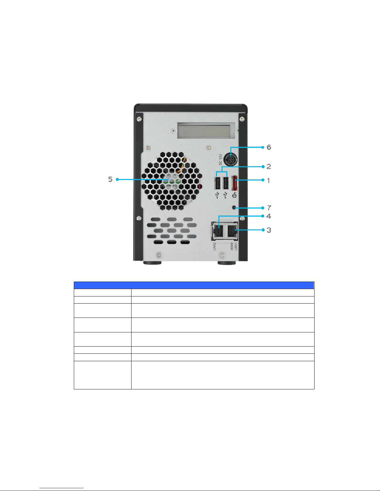
N3200XXX/N0503:
The N3200XXX/N0503 rear panel features ports and connectors.
Back Panel
Item Description
eSATA Port eSATA port for high-speed storage expansion
USB Port USB 2.0 port for compatible USB devices, such as digital cameras,
USB disks, and USB printers
WAN/LAN1 Port WAN/LAN1 port for connecting to an Ethernet network through a
switch or router
LAN2 Port LAN2 port that can be used for connection sharing
System Fan System fan that exhausts heat from the unit
Power Connector Connect the included power cords to these connectors
Reset Button
Resets the N3200XXX/N0503
Immediately press and hold the Reset button on the back for 5
seconds. This will reset your network setting, password, and turn
off Jumbo Frame Support.
Page 26

26
N4100PRO
The rear panel of the N4100PRO houses the USB and Ethernet connections, as well
as the power connector. See the table below for descriptions of each:
Item Description
Power Connector Connect the included power cord to this connector
WAN Port WAN port for connecting to an Ethernet network through a switch
or router
LAN Port LAN port for connecting to an Ethernet network through a switch or
router
USB Ports
USB 2.0 ports for storage expansion
Page 27

27
N4200 series:
The N4200 rear panel features ports and connectors.
Back Panel
Item Description
Power Connector For connect the power adaptor
WAN/LAN1 Port WAN/LAN1 port for connecting to an Ethernet network through a
switch or router
LAN2 Port LAN2 port for connecting to an Ethernet network through a switch
or router
USB Ports
USB 2.0 ports for storage expansion
eSATA Ports eSATA port for high-speed storage expansion
Page 28
28
N5200XXX:
The N5200XXX rear panel features ports and connectors.
Back Panel
Item Description
1.WAN/LAN1 Port WAN/LAN1 port for connecting to an Ethernet network through a
switch or a router.
2.LAN2 Port LAN2 port for connecting to a local Ethernet network through a
switch or router.
3.Serial Port This port is for an external UPS device.
4.eSATA Port eSATA port for high-speed external storage expansion.
5.USB Port USB 2.0 port for compatible USB devices, such as USB disks and
USB printers.
6.System Fan System fan that exhausts heat from the unit.
7.Power Connector Connect the included power cord to this connector.
6
7 1 2 3 4 5
Page 29

29
N5500:
The N5500 rear panel features ports and connectors.
Back Panel
Item Description
1.WAN/LAN1 Port WAN/LAN1 port for connecting to an Ethernet network through a
switch or router.
2.LAN2 Port LAN2 port for connecting to an Ethernet network through a
switch or router.
3.Serial Port This port is for external UPS device.
4.eSATA Port eSATA port for high-speed storage expansion.
5.USB Port (Type A) USB 2.0 port for compatible USB devices, such as USB disks, and
USB printers.
6.System Fan System fan that exhausts heat from the unit.
7.Power Connector Connect the included power cord to this connector.
8.USB Port (Type B) USB 2.0 port to connect PC (Type B of target mode).
7
6 2 3 4 1 5 8
Page 30

30
N7700 series:
The N7700 rear panel features ports and connectors.
Back Panel
Item Description
1.LAN2 Port LAN2 port for connecting to a local Ethernet network through a
switch or router.
2.WAN/LAN1 Port WAN/LAN1 port for connecting to an Ethernet network through a
switch or router.
3.Serial Port This port is for an external UPS device.
4.eSATA Port eSATA port for high-speed storage expansion.
5.USB Port USB 2.0 port for compatible USB devices, such as USB disks, and
USB printers.
6.System Fan System fan that exhausts heat from the unit.
7.Power Connector Connect the included power cord to this connector.
Page 31

31
1U4200XXXR:
Locator LED
1U4200 Back Panel
Item Description
eSATA Port eSATA port for high-speed storage expansion.
USB Ports USB 2.0 ports for compatible USB devices, such as digital
cameras, USB disks, and USB printers.
WAN/LAN1 Port WAN/LAN1 port for connecting to an Ethernet network through a
switch or router.
LAN2 Port LAN2 port that can be used for connection sharing.
Power Switch Switch for power supply.
System Fan System fan that exhausts heat from the unit.
Serial Port This port is for factory use only.
Locator LED Identifies each NAS within a rack mount configuration.
Power Connector Connect the included power cords to these connectors.
1U4200XXXS:
The rear panel of the 1U4200XXXS is similar to the 1U4200XXXR, but with a single
power connector:
Locator LED
Page 32

32
1U4600R:
The rear panel of the 1U4600R houses most of the USB and Ethernet connections,
as well as the eSATA port, system fan, and power connector. See the table below for
descriptions of each:
Power Connector Power Connector
Power Switch Power Switch USB Ports (A Type) LAN2 Port
Power LED Power LED System Fan eSATA Port Serial Port
USB Ports (B Type) WAN/LAN1 Port
1U4600 Back Panel
Item Description
eSATA Port eSATA port for high-speed storage expansion
USB Ports USB 2.0 ports for compatible USB devices, such as digital
cameras, USB disks, and USB printers
WAN/LAN1 Port WAN/LAN1 port for connecting to an Ethernet network through a
switch or router
LAN2 Port LAN2 port that can be used for connection sharing
Power Switch Switch for power supply
System Fan System fan that exhausts heat from the unit
Serial Port This port is for factory use only
Power Connector Connect the included power cords to these connectors
1U4600S:
The rear panel of the 1U4600S is similar to the 1U4600R, but with a single power
connector:
Power Connector
Power Switch USB Ports (A Type) LAN2 Port
System Fan eSATA Port Serial Port
USB Ports (B Type) WAN/LAN1 Port
Page 33

33
N8200XXX:
The N8200XXX rear panel features ports and connectors.
4 7
1 2 3 8 5 6
Back Panel
Item Description
1.Power Connector Connect the included power cords to these connectors.
2.Power Switch Powers the N8200XXX on/off.
3.eSATA Port eSATA port for high-speed storage expansion.
4.USB Port USB 2.0 port for compatible USB devices, such as USB disks, and
USB printers.
5.Serial Port This port is for an external UPS device.
6.WAN/LAN1 Port WAN/LAN1 port for connecting to an Ethernet network through a
switch or router.
7.LAN2 Port WAN/LAN1 port for connecting to a local Ethernet network
through a switch or router.
8. Locator LED Identifies each NAS within a rack mount configuration.
Page 34

34
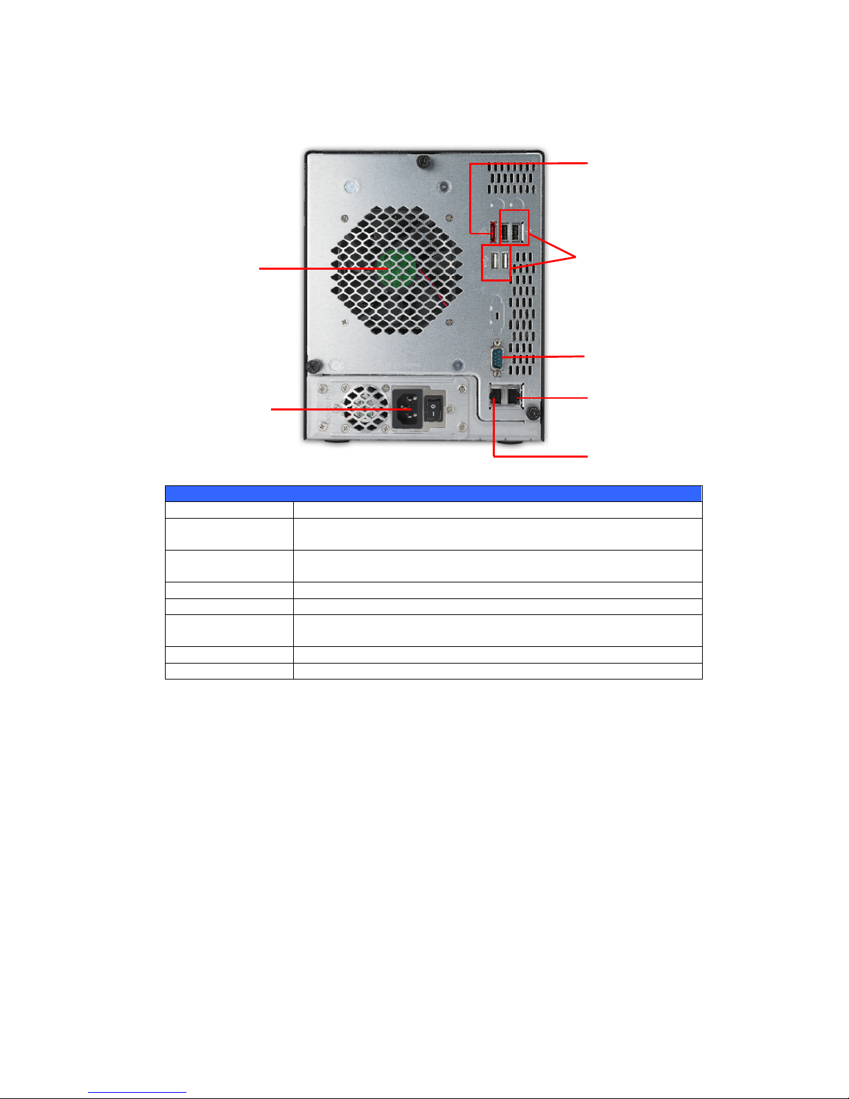
N8800 series:
The N8800 rear panel features ports and connectors.
Back Panel
Item Description
1.Power Connector Connect the included power cords to these connectors
2.Power Switch Switch for power supply
3.eSATA Port eSATA port for high-speed storage expansion
4.USB Port USB 2.0 port for compatible USB devices, such as USB disks, and
USB printers
5.Serial Port This port is for external UPS device
6.WAN/LAN1 Port WAN/LAN1 port for connecting to an Ethernet network through a
switch or router
7.LAN2 Port WAN/LAN1 port for connecting to an Ethernet network through a
switch or router
N8800PRO
(SP)
is Single power
Page 35

35
N8900
Back Panel
Item Description
1.Power Connector Connect the included power cords to these connectors
2.Serial Port This port is for external UPS device
3.eSATA Port eSATA port for high-speed storage expansion
4.USB Port USB 2.0 port for compatible USB devices, such as USB disks, and
USB printers
5.USB Port USB 3.0 port for compatible USB devices.
6.WAN/LAN1 Port WAN/LAN1 port for connecting to an Ethernet network through a
switch or router
7.LAN2 Port WAN/LAN1 port for connecting to an Ethernet network through a
switch or router
8.LAN3 Port LAN3 port for HA connecting.
Page 36
36
Chapter 2: Hardware Installation
Overview
Your Thecus IP storage is designed for easy installation. To help you get started, the
following chapter will help you quickly get your Thecus IP storage up and running.
Please read it carefully to prevent damaging your unit during installation.
Before You Begin
Before you begin, be sure to take the following precautions:
1. Read and understand the Safety Warnings outlined in the beginning of the
manual.
2. If possible, wear an anti-static wrist strap during installation to prevent static
discharge from damaging the sensitive electronic components on the Thecus
IP storage.
3. Be careful not to use magnetized screwdrivers around the Thecus IP
storage’s electronic components.
Cable Connections
To connect the N2200XXX to your network, follow the steps below:
1. Connect an Ethernet cable from your network to the WAN/LAN1 port on the
back panel of the N2200XXX.
2. Connect the provided power cord into the power socket on the back panel.
Plug the other end of the cord into a surge protected socket.
1
2
Page 37

37
3. Press the power button to boot up the N2200XXX.
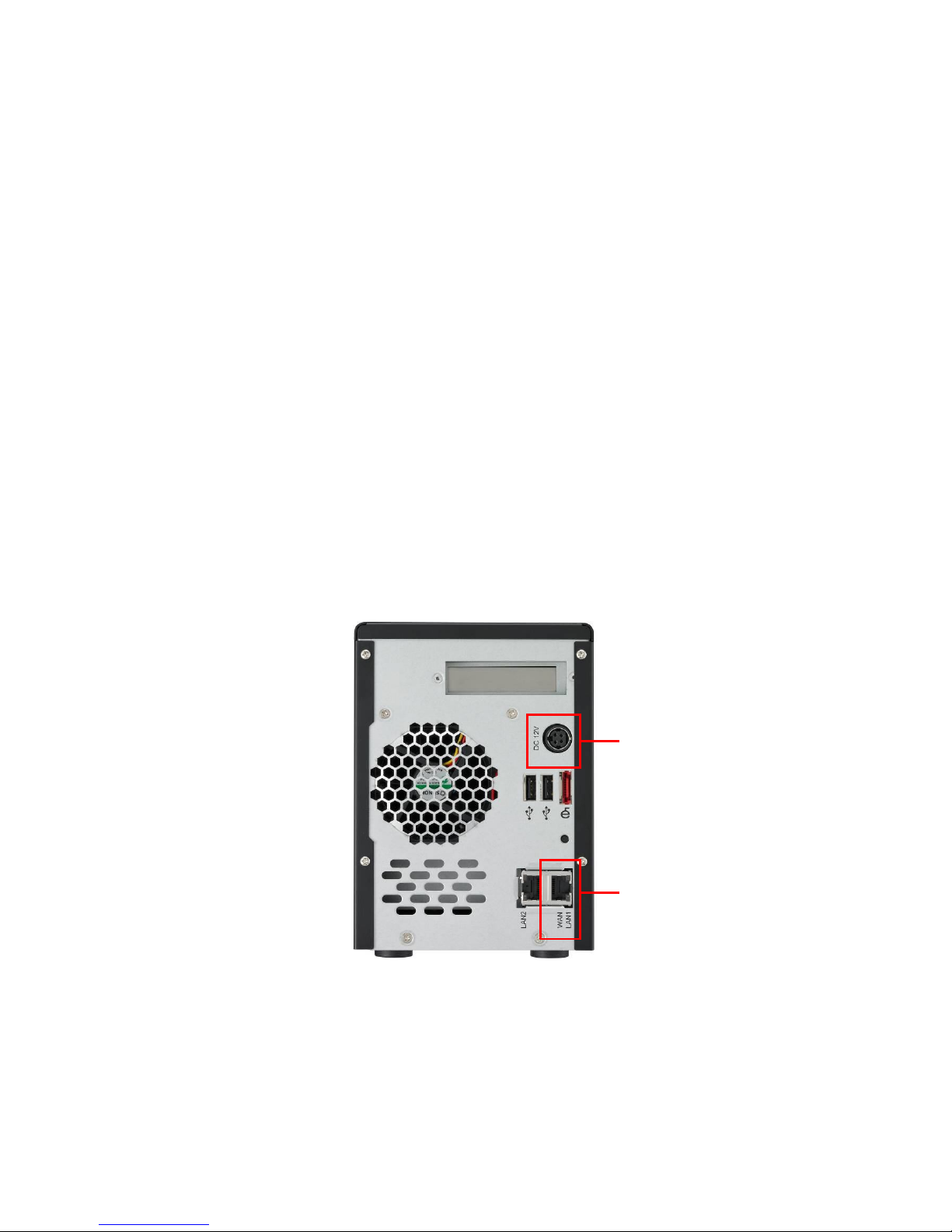
To connect the N3200XXX/N0503 to your network, follow the steps below:
1. Connect an Ethernet cable from your network to the WAN/LAN1 port on the
back panel of the N3200XXX/N0503.
2. Connect the provided power cord into the power socket on the back panel.
Plug the other end of the cord into a surge protected socket.
3
Page 38

38
3. Open the front door then press the power button to boot up the
N3200XXX/N0503.
Make the following connections on the Thecus N4100PRO and then power up the
unit:
1. Connect an Ethernet cable from your network to the WAN port on the back
panel of the N4100PRO.
2. Connect the provided power cord into the universal power socket on the
back panel. Plug the other end of the cord into a surge protected socket.
3. Press the power button on the front panel to power on the N4100PRO.
Checking System Status
After making connections on the N4100PRO and powering up, check whether the
system status is normal or has trouble by observing indicators on the front panel
and hard disk trays.
System Status Normal
The system status is normal if:
1. The front panel Power LED glows blue and the WAN LED glows or blinks
green.
2. The HDD Power LED on each HDD tray glows blue.
System Trouble
The system has trouble if:
1. Any LED glows red.
1. The system emits a continuous beeping sound.
If the system has trouble, please refer to Chapter 8: Troubleshooting.
WARNING
There are no user serviceable parts inside the N4100PRO. Please contact
Page 39

39
To connect N4200 series NAS to your network, follow the steps below:
1. Connect an Ethernet cable from your network to the WAN/LAN1 port on the
back panel of the N4200.
2. Connect the provided power cord into the universal power socket on the back
panel. Plug the other end of the cord into a surge protected socket.
3. Press the power button on the Front Panel to boot up the N4200.
To connect the N5200XXX/N5500 to your network, follow the steps below:
1. Connect an Ethernet cable from your network to the WAN/LAN1 port on the
back panel of the N5200XXX/N5500.
2. Connect the provided power cord into the universal power socket on the back
panel. Plug the other end of the cord into a surge protected socket. Press the
power supply switch to turn on the power supply.
Page 40

40
3. Press the power button on the front panel to boot up the N5200XXX/N5500.
To connect the 1U4200XXX/1U4600 to your network, follow the steps below:
1. Connect an Ethernet cable from your network to the WAN/LAN1 port on the
back panel of the 1U4200XXX/1U4600.
2. Connect the provided power cord into the universal power socket on the back
panel. Plug the other end of the cord into a surge protected socket. Press the
power supply switch to turn on the power supply.
NOTE
If you are installing the 1U4200XXXR/1U4600R, be sure to
connect both power cables. If you do not, the system will
assume one power supply has failed, and an alarm will sound.
Page 41

41
3. Press the power button on the front panel to boot up the
1U4200XXX/1U4600.
To connect N7700 series NAS to your network, follow the steps below:
1. Connect an Ethernet cable from your network
to the WAN/LAN1 port on the back panel of
the N7700.
2. Connect the provided power cord into the universal power socket on the back
panel. Plug the other end of the cord into a surge protected socket. Press the
power supply switch to turn on the power supply.
3. Press the power button on the Front Panel to boot up the N7700.
Page 42

42
To connect N8200XXX/N8800 series NAS to your network, follow the steps below:
1. Connect an Ethernet cable from your network to the WAN/LAN1 port on the
back panel of the N8200XXX/N8800.
2. Connect the provided power cord into the universal power socket on the back
panel. Plug the other end of the cord into a surge protected socket. Press the
power supply switch to turn on the power supply.
3. Press the power button on the front panel to boot up the N8200XXX/N8800.
Page 43

43
To connect the N8900 series products to your network, follow the steps below:
1. Connect an Ethernet cable from your network to the WAN/LAN1 port on the
back panel of the N8900
2. Connect the provided power cord into the universal power socket on the back
panel. Plug the other end of the cord into a surge protector socket.
Page 44
44
3.Press the power button on the Front Panel to boot up the N8900.
Page 45
45
Chapter 3: First Time Setup
Overview
Once the hardware is installed, physically connected to your network, and powered
on, you can configure the Thecus IP storage so that it is accessible to your network
users. There are two ways to set up your Thecus IP storage: using the Thecus
Setup Wizard or the LCD display. Follow the steps below for initial software setup.
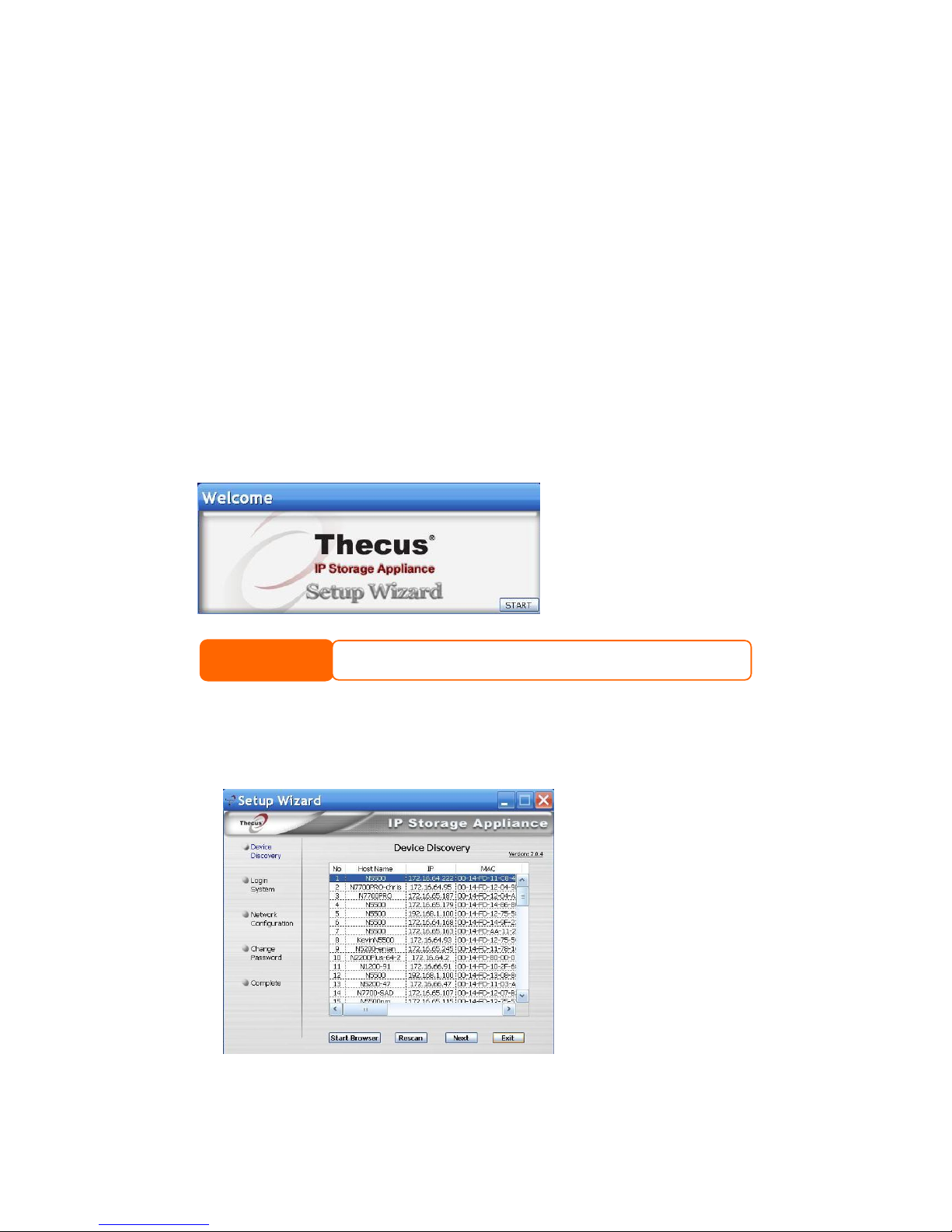
Thecus Setup Wizard
The handy Thecus Setup Wizard makes configuring Thecus IP storage a snap. To
configure the Thecus IP storage using the Setup Wizard, perform the following
steps:
1. Insert the installation CD into your CD-ROM drive (the host PC must be
connected to the network).
2. The Setup Wizard should launch automatically. If not, please browse your
CD-ROM drive and double click on Setup.exe.
3. The Setup Wizard will start and automatically detect all Thecus storage
devices on your network. If none are found, please check your connection
and refer to Chapter 7: Troubleshooting for assistance.
4. Select the Thecus IP storage that you like to configure.
NOTE
For MAC OS X users, double click on Thecus Setup Wizard .dmg fil e.
Page 46

46
5. Login with the administrator account and password. The default account and
password are both “admin”.
6. Name your Thecus IP storage and configure the network IP address. If your
switch or router is configured as a DHCP Server, configuring the Thecus IP
storage to automatically obtain an IP address is recommended. You may also
use a static IP address and enter the DNS Server address manually.
7. Change the default administrator password.
Page 47

47
8. Finished! Access the Thecus IP storage Web Administrator Interface by
pressing the Start Browser button. You can also configure another Thecus
IP storage at this point by clicking the Setup Other Device button. Press
Exit to exit the wizard.
LCD Operation (N4100PRO/N5200XXX/N5500/1U4200XXX/1U4600/N7700
series/N8200XXX/N8800 series)
The mentioned models above are equipped with an LCD on the front for easy status
display and setup. There are four buttons on the front panel to control the LCD
functions.
LCD Controls
Use the Up (▲), Down (▼), Enter () and Escape (ESC) keys to select various
configuration settings and menu options for Thecus IP storage configuration.
The following table illustrates the keys on the front control panel:
LCD Controls
Icon Function Description
▲
Up Button Select the previous configuration settings option.
▼
Down Button USB copy confirmation display.
Enter Enter the selected menu option, sub-menu, or parameter setting.
ESC Escape Escape and return to the previous menu.
There are two modes of operation for the LCD: Display Mode and Management
Mode.
NOTE
The T hecus Setup Wizard is designed for installation on systems running Windows
XP/2000/vista/7 or Mac OSX or later. Users with other operating systems will
need to install the Thecus Setup Wizard on a host machine with one of these
operating systems before using the unit.
Page 48

48
Display Mode
During normal operation, the LCD will be in Display Mode.
Display Mode
Item Description
Host Name Current host name of the system.
WAN/LAN1 Current WAN/LAN1 IP setting.
LAN2 Current LAN2 IP setting.
Link Aggregation Current Link Aggregation status
System Fan1 Current system fan1 status.
System Fan2 Current system fan2 status.
CPU Fan Current CPU fan status
2009/05/22 12:00 Current system time.
Disk Info Current status of disk slot has been installed
RAID Current RAID status.
The Thecus IP storage will rotate these messages every one-two seconds on the
LCD display.
USB Copy
The USB Copy function enables you to copy files stored on USB devices such as USB
disks and digital cameras to the Thecus IP storage by press button. To use USB copy,
follow the steps below:
1. Plug your USB device into an available USB port on the Front end.
2. In Display Mode, press the Down Button (▼).
3. The LCD will display “USB Copy?”
4. Press Enter () and the Thecus IP storage will start copying USB disks
connected to the front USB port.
5. All of data will be copied into system folder named “USB copy”.
Management Mode
During setup and configuration, the LCD will be in Management Mode.
To enter into Management Mode, press Enter () and an “Enter Password” prompt
will show on the LCD.
At this time, the administrator has to enter the correct LCD password. System will
check whether the correct LCD password has been entered. The default LCD
password is “ 0000 ”. If correct password is entered, you will enter into the
Management Mode menu.
Management Mode
Item Description
WAN/LAN1 Setting IP address and netmask of your WAN/LAN1 ports.
LAN2 Setting IP address and netmask of your LAN2 ports.
Link Agg. Setting Select Load Balance, 802.3ad or Failover.
Change Admin Passwd Change administrator’s password for LCD operation.
Reset to Default Reset system to factory defaults.
Exit Exit Management Mode and return to Display Mode.
Page 49

49
LCD Operation (N3200XXX/N0503)
LCD Controls
Use the Down (▼), Up (▲), Enter () and Escape (ESC) keys to operate LCD to
view system information and USB copy.
The following table illustrates the keys on the front control panel:
LCD Controls
Icon Function Description
▼ Down Button Select the previous configuration settings option.
▲ Up Button Select the next configuration settings option.
Enter Enter to display USB copy operation.
ESC Escape Escape to give up USB copy.
Press and hold for 3 seconds to turn off the LCD’s backlight. Press
any button to switch the backlight back on.
Display Mode
During normal operation, the LCD will be in Display Mode.
Display Mode
Item Description
Host Name Current host name of the system.
WAN/LAN1 Current WAN/LAN1 IP setting.
LAN2 Current LAN2 IP setting.
RAID Current RAID status.
System Fan Current system fan status.
Temperature Current system temperature.
Date/Time Current system date and time
Up Time The system power on time since last start
The N3200XXX/N0503 will rotate these messages every three seconds on the LCD
display.
USB Copy
The USB Copy function enables you to copy files stored on USB devices such as USB
disks and digital cameras to the N3200XXX/N0503 with a press of a button. To use
USB copy, follow the steps below:
1. Plug your USB device into an available USB port on the Front Panel.
2. In Display Mode, press the Enter ().
3. The LCD will display “USB Copy?”
NOTE
You can also change your LCD password using the Web Administration
Interface by navigating to System Management > Administrator
Password. For more on the Web Administration Interface, see Chapter
4: System Management.
NOTE
If the RAID array is in a degraded state, the LCD display will be stopped
in display mode and show which disk is degraded in the array:
RAID: Degraded [Disk #]
Page 50

50
4. Press Enter () and theN3200XXX/N0503 will start copying USB disks
connected to the front USB port. The LCD will display the USB copy progress
and results.
OLED Operation (N4200 series/N8900)
OLED Operation
The mentioned models above are equipped with an OLED on the front for easy
status display and setup. There are four buttons on the front panel to control the
OLED functions.
OLED Controls
Use the Up (▲), Down (▼), Enter () and Escape (ESC) keys to select various
configuration settings and menu options for N4200series/N8900 configuration.
The following table illustrates the keys on the front control panel:
OLED Controls
Icon Function Description
▲
Up Button Select the previous configuration settings option.
▼
Down Button USB copy confirmation display.
Enter Enter the selected menu option, sub-menu, or parameter setting.
ESC Escape Escape and return to the previous menu.
There are two modes of operation for the OLED: Display Mode and Management
Mode.
Display Mode
During normal operation, the OLED will be in Display Mode.
Display Mode
Item Description
Host Name Current host name of the system.
WAN/LAN1 Current WAN/LAN1 IP setting.
LAN2 Current LAN2 IP setting.
Link Aggregation Current Link Aggregation status
System Fan Current system fan status.
CPU Fan Current CPU fan status
2009/05/22 12:00 Current system time.
RAID Current RAID status.
The N4200 series/N8900 will rotate these messages every one-two seconds on the
OLED display.
Page 51

51
Typical Setup Procedure
From the Web Administration Interface, you can begin to setup your Thecus IP
storage for use on your network. Setting up the Thecus IP storage typically follows
the five steps outlined below.
For more on how to use the Web Administration Interface, see
Chapter 4: Web Administration Interface.
Step 1: Network Setup
From the Web Administration Interface, you can configure the network settings of
the Thecus IP storage for your network. You can access the Network menu from
the menu bar.
For details on how to configure your network settings, refer to
Chapter 4: System Network .
Step 2: RAID Creation
Next, administrators can configure their preferred RAID setting and build their RAID
volume. You can access RAID settings from the menu bar of the Web Administration
Interface by navigating to Storage Management > RAID Configuration.
For more information on configuring RAID, see
Chapter 4: System Management > RAID Configuration.
Don’t know which RAID level to use? Find out more about the different RAID levels
from Appendix B: RAID Basics.
Step 3: Create Local Users or Setup Authentication
Once the RAID is ready, you can begin to create local users for Thecus IP storage, or
choose to setup authentication protocols such as Active Directory (AD).
For more on managing users, go to Chapter 4:User and Group Authentication.
For more information on configuring Active Directory, see
Chapter 4: User and Group Authentication > ADS/NT Support.
For information about the benefits of Active Directory, see Appendix C: Active
Directory Basics.
Step 4: Create Folders and Set Up ACLs
Once users are introduced into your network, you can begin to create various folders
on the Thecus IP storage and control user access to each using Folder Access
Control Lists.
More information on managing folders, see
Chapter 4: Storage Management> Share Folder .
To find out about configuring Folder Access Control Lists, see Chapter 4: Storage
Management > Share Folder> Folder Access Control List (ACL).
Step 5: Start Services
Finally, you can start to setup the different services of Thecus IP storage for the
users on your network. You can find out more about each of these services by
clicking below:
Page 52

52
SMB/CIFS
Apple File Protocol (AFP)
Network File System (NFS)
File Transfer Protocol (FTP)
iTunes Server
Printer Server
Photo Server
Page 53

53
Chapter 4: System Administration
Overview
The Thecus IP storage provides an easily accessible Web Administration
Interface. With it, you can configure and monitor the Thecus IP storage anywhere
on the network.
Web Administration Interface
Make sure your network is connected to the Internet. To access Thecus IP storage
Web Administration Interface:
1. Type the Thecus IP storage IP address into your browser. (Default IP address
is http://192.168.1.100)
NOTE
Your computer’s network IP address must be on the same subnet as the Thecus
IP storage. If the Thecus IP storage has default IP address of 192.168.1.100,
your managing PC IP address must be 192.168.1.x, where x is a number
between 1 and 254, but not 100.
NOTE
This page can be displayed with Flash or with HTML. Choose Flash for Fl ash
(shown in the top figure) and Traditional for HTML (shown in the bottom
figure).
Page 54

54
2. Login to the system using the administrator user name and password. The
factory defaults are:
User Name: admin
Password: admin
※ If you changed your password in the setup wizard, use the new password.
Once you are logged in as an administrator disclaimer page will appear as below.
Please click the check box if you do not want to have this page displayed during the
next login.
Following by disclaim page, you will see the Web Administration Interface. From
here, you can configure and monitor virtually every aspect of the Thecus IP storage
from anywhere on the network.
My Favorite
The user interface with “My Favorite” shortcut is allowed user to designate often
used items and have them display on the main screen area. The figure below
displays 12 default favorite functions.
Page 55

55
Administrators can add or remove favorite functions to My Favorites by right clicking
the mouse on the menu tree.
The other way administrators can add favorite functions is by clicking the “Add
Favorite” icon in each function screen. Please refer figure below in red circuit icon.
To return to the favorite screen, simply click “Home” located at the left hand corner
of the main screen.
Page 56
56
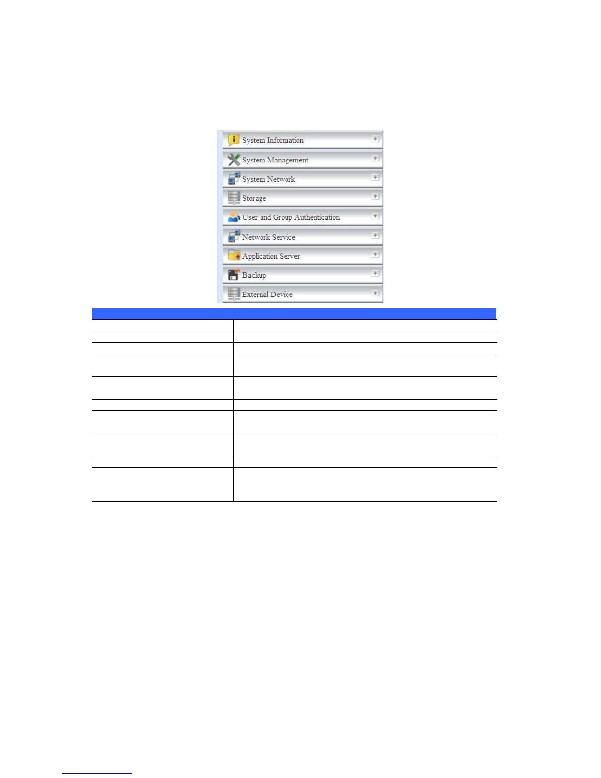
Menu Bar
The Menu Bar is where you will find all of the information screens and system
settings of Thecus IP storage. The various settings are placed in the following
groups on the menu bar:
Menu Bar
Item Description
System Information Current system status of the Thecus IP storage.
System Management Various Thecus IP storage system settings and information.
System Network Information and settings for network connections, as well as
various services of the Thecus IP storage.
Storage Information and settings for storage devices installed into the
Thecus IP storage.
User and Group Authentication Allows configuration of users and groups.
Network Service Setup and manage protocols such as Samba/CIFS, AFP, NFS,
FTP, and other network services.
Application Server Printer Server and iTunes Server to set up of the Thecus IP
storage.
Backup Category of Backup Features set up of the Thecus IP storage.
External Device
Thecus IP storage support printer serving and UPS backup
power supplies.
Moving your cursor over any of these items will display the dropdown menu
selections for each group.
In the following sections, you will find detailed explanations of each function, and
how to configure your Thecus IP storage.
Page 57

57
Message Bar
You can get information about system status quickly by moving mouse over.
Message Bar
Item Status Description
RAID Information.
Display the status of created RAID volume. Click
to go to RAID information page as short cut.
Disks Information.
Display the status of disks installed in the
system. Click to go to Disk information page as
short cut.
FAN.
Display system FAN Status. Click to go to
System Status page as short cut.
Network.
Green: The system is connected to the Internet.
Red: The system is unable to connect to the
Internet.
‧Web Disk
Click this to log into the Web Disk.
‧Photos
Click this to log into the photo server.
‧News
Accesses online registration and the latest release news.
‧Log
Accesses the system log. New logs will be displayed with an icon here.
‧Language Selection
The Thecus IP storage supports multiple Languages, including:
English,Japanese,Traditional Chinese,Simplified Chinese,French,German,Italian,
Korean,Spanish,Russia,Polish,Portugal
On the menu bar, click Language and the selection list appears. This user interface
will switch to selected Language for Thecus IP storage.
‧Help
Click this to toggle the help page open and browse or search through the UI help
database. The current page’s help section will be displayed first.
‧My Favorite
Add/Remove the current page from the Home page.
Page 58

58
‧Shutdown
Choose Shutdown or Reboot from the dropdown menu to shutdown or reboot
your NAS.
‧Logout
Click to log out of Web Administration Interface.
System Information
Information provides viewing on current Product info, System Status, Service
Status and Logs.
The menu bar allows you to see various aspects of the Thecus IP storage. From here,
you can discover the status of the Thecus IP storage, and also other details.
General Information
Once you login, you will first see the basic Product Information screen providing
Manufacturer, Product No., Firmware Version, and System Up Time
information.
Product Information
Item Description
Manufacturer Displays the name of the system manufacturer.
Product No. Shows the model number of the system.
Firmware version Shows the current firmware version.
Up time Displays the total run time of the system.
System/Service Status
(N3200XXX/N0503/N4100PRO/N4200series/N5200XXX/N5500/1U4200XXX/
1U4600/N7700 series/N2200XXX/N8200XXX/N8800 series)
From the Status menu, choose the System item, System Status and Service
Status screens appear. These screens provide basic system and service status
information.
Page 59

59
System Status
Item Description
CPU Loading (%) Displays current CPU workload of the Thecus IP storage.
CPU Fan Speed Displays current CPU fan status.
System Fan Speed Displays the current status of the system fan.
Up Time Shows how long the system has been up and running.
Service Status
Item Description
AFP Status The status of the Apple Filing Protocol server.
NFS Status The status of the Network File Service Server.
SMB/CIFS Status The status of the SMB/CIFS server.
FTP Status The status of the FTP server.
TFTP Status The status of the TFTP server.
Nsync Status The status of the Nsync server.
UPnP Status The status of the UPnP service.
SNMP The status of the SNMP service.
System/Service Status (For the N8900)
From the Status menu, choose the System item, System Status and Service
Status screens appear. These screens provide basic system and service status
information.
Page 60

60
System Status
Item Description
CPU Loading (%) Displays current CPU workload of the Thecus IP storage.
CPU Fan Speed Displays current CPU fan status.
System Fan 1 Speed Displays current System fan (left 1) status
System Fan 2 Speed Displays current System fan (left 2) status
CPU Temperature Displays current CPU Temperature.
System Temperature 1 Displays current System temperature in position 1
System Temperature 2 Displays current System temperature in position 2
System Temperature 3 Displays current System temperature in position 3
System Temperature 4 Displays current System temperature in position 4
Up Time Shows how long the system has been up and running.
Service Status
Item Description
AFP Status The status of the Apple Filing Protocol server.
NFS Status The status of the Network File Service Server.
SMB/CIFS Status The status of the SMB/CIFS server.
FTP Status The status of the FTP server.
TFTP Status The status of the TFTP server.
Rsync Status The status of the Rsync server.
UPnP Status The status of the UPnP service.
SNMP The status of the SNMP service.
Logs
From the System Information menu, choose the Logs item and the System Logs
screen appears. This screen shows a history of system usage and important events
such as disk status, network information, and system booting. See the following
table for a detailed description of each item:
Page 61

61
See the following table for a detailed description of each item:
System Logs
Item Description
All Provides all log information including system messages, warning
messages and error messages.
INFO Records information about system messages.
WARN Shows only warning messages.
ERROR Shows only error messages.
Download All Log File Export all logs to an external file.
Truncate All Log File Clear all log files.
The number of lines per
page □
Specify desired number of lines to display per page.
Sort Ascending Shows logs by date in ascending order.
Sort Descending Shows logs by date in descending order.
|<< < > >>| Use the forward ( > >>| ) and backward ( |<< < ) buttons to
browse the log pages.
Re-loading logs.
On-line Register
From the System Information menu, choose the On-line Register item and the
System On-line Register screen appears. The on-line register service can
periodically update the user when new firmware and software modules are released
by Thecus. To enable this service, simply check the “Enable” check box. By enabling
this service, the items in bold will be sent to Thecus via the Internet.
Other than the defined items sent upon registration, there are also two additional
items: “HDD Info” and “Time Zone”. These two optional items can also be sent to
Thecus anonymously for analysis and statistics purposes. To send these items,
simply check the desired checkboxes to help Thecus improve its products and
services.
Page 62

62
Syslog Management
Generates system log messages for the syslog server.
These messages are stored on your NAS in: Nsync > log> messages.
Information can be obtained in two ways: locally and remotely.
Local Access - When Local is selected, log messages can be viewed directly
through samba. However, to access the Nsync folder through samba, the folder
must be set as browseable and the user must be given ACL permissions. In OS X,
UNIX extensions must be disabled under Network Service > Samba/CIFS in the UI.
Remote Access - They can also be viewed remotely by selecting Remote and
inputting a Remote IP Address into the input field. This will allow a TFTP program,
such as TFTPd32, to access the system log remotely from a computer.
System Management
The System Management menu gives you a wealth of settings that you can use to
configure your Thecus IP storage system administration functions. You can set up
system time, system notifications, and even upgrade firmware from this menu.
Page 63

63
Date and Time: System Date and settings
From the Date and time menu, choose the item and the screen appears. Set the
desired Date, Time, and Time Zone. You can also elect to synchronize the system
time on Thecus IP storage with an NTP (Network Time Protocol) Server.
See the following table for a detailed description of each item:
Time
Item Description
Date Sets the system date.
Time Sets the system time.
Time Zone Sets the system time zone.
NTP Server
Select Enable to synchronize with the NTP server.
Select Disable to close the NTP server synchronization.
Sync with external NTP
Server
Select YES to allow Thecus IP storage to synchronize with an NTP
server of your choice. Press Apply to change.
WARNING
If an NTP server is selected, pl ease make sure your Thecus IP storage has been
setup to access the NTP server.
Page 64
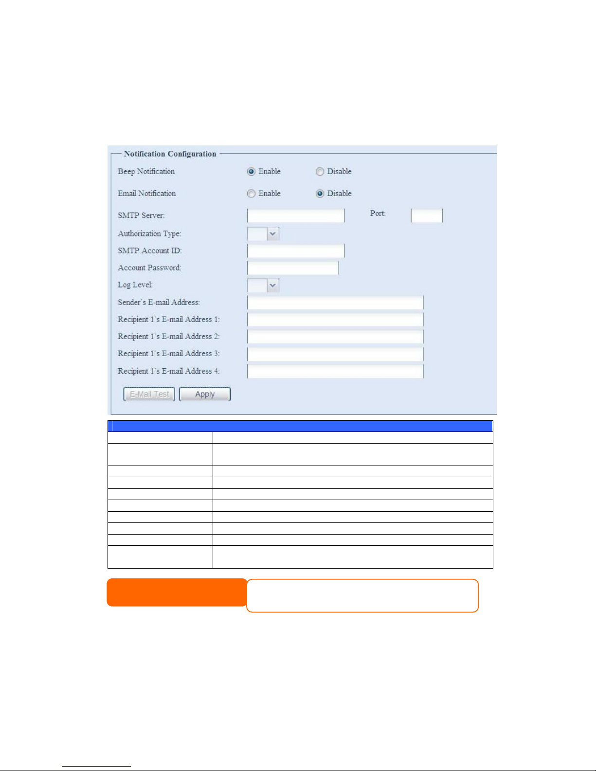
64
Notification configuration
From the menu, choose the Notification item, and the Notification
Configuration screen appears. This screen lets you have Thecus IP storage notify
you in case of any system malfunction. Press Apply to confirm all settings. See
following table for a detailed description of each item.
Notification Configuration
Item Description
Beep Notification Enable or disable the system beeper that beeps when a problem
occurs.
Email Notification Enable or disable email notifications of system problems.
SMTP Server Specifies the hostname/IP address of the SMTP server.
Port Specifies the port to send outgoing notification emails.
Auth Type Select the SMTP Server account authentication type.
SMTP Account ID Set the SMTP Server Email account ID.
Account Password Enter a new password.
E-mail From Set email address to send email.
Receiver’s E-mail
Address (1,2,3,4)
Add one or more recipient’s email addresses to receive email
notifications.
NOTE
Consult with your mail server administrator for email server
information.
Page 65

65
Firmware Upgrade
From the menu, choose the Firmware Upgrade item and the Firmware Upgrade
screen appears.
Follow the steps below to upgrade your firmware:
1. Use the Browse button to find the firmware file.
2. Press Apply.
3. The beeper beeps and the Busy LED blinks until the upgrade is complete.
Schedule Power On/Off
Using the Thecus IP storage System Management, you can save energy and money
by scheduling the Thecus IP storage to turn itself on and off during certain times of
the day.
From the menu, choose the Schedule Power On/Off item and the Schedule
Power On/Off screen appears.
To designate a schedule for the Thecus IP storage to turn on and off, first enable the
feature by checking the Enable Schedule Power On/Off checkbox.
Then, simply choose an on and off time for each day of the week that you would like
to designate a schedule by using the various dropdowns.
Finally, click Apply to save your changes.
NOTE
• The beeper only beeps if it is enabled in the System Notification menu.
• Check Thecus website for the latest firmware release and release notes.
• Downgrading firmware is not permitted.
WARNING
Do not turns off the system during the fi rmware upgrade process.
This will lead to a catastrophic result that may render the system inoperable.
NOTE
•Save old firmware images and system configuration files before upgrading firmware in
case the system needs it later on. The backup files can will be stored on a USB disk if
available or in the nsync folder on your RAID partition. The backup will take
approximately 3-5 minutes to complete before carrying on with the firmware upgrade.
Page 66

66
Example - Monday: On: 8:00; Off: 16:00
System will turn on at 8:00 AM on Monday, and off at 16:00 on Monday. System will
turn on for the rest of the week.
If you choose an on time, but do not assign an off time, the system will turn on and
remain on until a scheduled off time is reached, or if the unit is shutdown manually.
Example - Monday: On: 8:00
System will turn on at 8:00 AM on Monday, and will not shut down unless powered
down manually.
You may also choose two on times or two off times on a particular day, and the
system will act accordingly.
Example - Monday: Off: 8:00; Off: 16:00
System will turn off at 8:00 AM on Monday. System will turn off at 16:00 PM on
Monday, if it was on. If the system was already off at 16:00 PM on Monday, system
will stay off.
Administrator password
From the menu, choose the Administrator Password item and the Change
Administrator Password screen appears. Enter a new password in the New
Password box and confirm your new password in the Confirm Password box.
Press Apply to confirm password changes.
There is also password for enter LCD setting you could setup here. (Does not apply
to the N8900) Enter a new password in the New Password box and confirm your
new password in the Confirm Password box. Press Apply to confirm password
changes.
Page 67

67
See the following table for a detailed description of each item.
Change Administrator and LCD Entry Password
Item Description
New Password Type in a new administrator password.
Confirm Password Type the new password again to confirm.
Apply Press this to save your changes.
Config Mgmt
From the menu, choose the Config Mgmt item and the System Configuration
Download/Upload screen appears. From here, you can download or upload stored
system configurations.
See the following table for a detailed description of each item.
System Configuration Download/Upload
Item Description
Download Save and export the current system configuration.
Upload Import a saved configuration file to overwrite current system
configuration.
NOTE
Backing up your system configuration is a great way to ensure that you can revert
to a working configuration when you are experimenting with new system settings.
The system configuration you have backup can be only restore in same firmware
version. And the backup details have excluded user/group accounts.
Page 68

68
Factory default
From the menu, choose the Factory Default item and the Reset to Factory
Default screen appears. Press Apply to reset Thecus IP storage to factory default
settings.
Reboot & Shutdown
From the menu, choose Reboot & Shutdown item, and the Shutdown/Reboot
System screen appears. Press Reboot to restart the system or Shutdown to turn
the system off.
File System check
The File System Check allows you to perform a check on the integrity of your disks’
file system. Under the menu, click File system Check and the File System Check
prompt appears.
To perform a file system check, click Apply.
Once clicked, the following prompt will appear:
Click Yes to reboot the system.
WARNING
Resetting to factory defaults will not erase the data stored in the hard disks, but
WILL revert all the settings to the factory default values.
Page 69

69
Once the system has rebooted, you will be returned to the File System Check
prompt. There you will see the available RAID volumes to run the file system check
on except ZFS volume, ZFS has no need to perform file system check. Check the
desired RAID volumes and click Next to proceed with the file system check. Click
Reboot to reboot without running the check.
Once you click Next, you will see the following screen:
Click Start to begin the file system check. Click Reboot to reboot the system.
When the file system check is run, the system will show 20 lines of information until
it is complete. Once complete, the results will be shown at the bottom.
Page 70
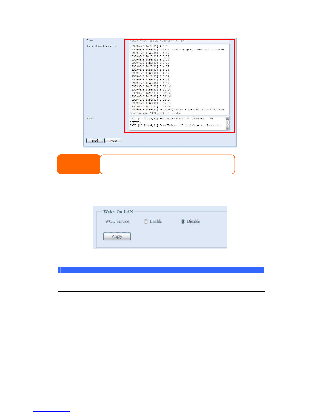
70
Wake-Up On LAN (WOL)
The Thecus IP storage has the ability to be awoken from sleep mode via WAN/LAN1
port.
From the menu, choose the WOL item, and the Wake-up On LAN screen appears.
From here, you can Enable or Disable.
Wake-up On LAN Configuration
Item Description
WOL Service Enable or Disable WOL service
Apply Click Apply to save changes.
SNMP Support
From the menu, choose the SNMP item and the SNMP Support screen appears.
You could enable the SNMP function and filled in the related information in each
fields. With the SNMP management software could get system basic information.
NOTE
The system must be rebooted before Thecus IP storage can function
normally after file system check complete.
Page 71
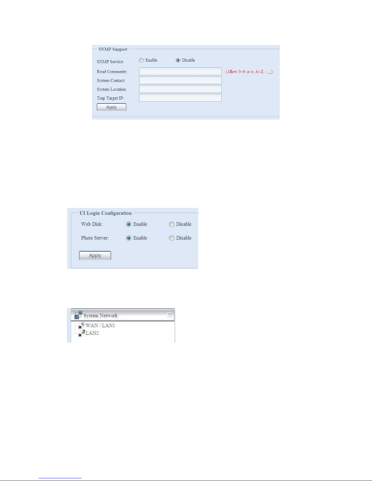
71
From the menu, choose the SNMP item, and the SNMP Support screen appears.
From here, you can Enable or Disable.
UI Login Configuration
Adjusts UI Login Configuration settings. You can enable/disable the Web Disk and
Photo Server functions, according to your needs.
For the 3X series, users need to install the photo server module or web disk module
to access these functions.
System Network
Use the System Network menu to make network configuration settings as well as
service support settings.
WAN/LAN1
WAN/LAN1 Configuration
From the System Network menu, choose WAN/LAN1, and the WAN/LAN1
Configuration screen appears. This screen displays the network parameters of the
WAN/LAN1 connection. You may change any of these items and press Apply to
confirm your settings. See a description of each item in the following table:
Page 72

72
WAN/LAN1 Configuration
Item Description
Host name Host name that identifies the Thecus IP storage on the network.
Domain name Specifies the domain name of Thecus IP storage.
WINS Server To set a server name for NetBIOS computer.
MAC Address MAC address of the network interface.
Jumbo Frame Support Enable or disable Jumbo Frame Support of the WAN/LAN1 interface on your
Thecus IP storage.
IP Sharing Mode When enabled, PCs connected to the LAN2 port will be able to access the
WAN/LAN1.
Link Aggregation Specifies whether WAN/LAN1 and LAN2 ports will be aggregated and act as
one port. There are 6 modes can be choose from:
Load Balance/Fail-over/Balance-XOR/802.3ad/Balance-TLB/Balance-ALB
Set IP Address by:
Static / Dynamic
You can choose a static IP or Dynamic IP, and input your network
configuration
IP IP address of the WAN/LAN1 interface.
Netmask Network mask, which is generally: 255.255.255.0
Gateway Default Gateway IP address.
DNS Server Domain Name Service (DNS) server IP address.
NOTE
• Only use Jumbo Frame settings when operating in a Gigabit environment
where all other clients have Jumbo Frame Setting enabled.
• Enabli ng DHCP automatically turns on UPnP— see the Service Support Screen.
• If you are only using the WAN/LAN1 port, we suggest that you disable IP
Sharing Mode. This will result in higher throughput.
• A correct DNS setting is vital to networks services, such as SMTP and NTP.
• To use the Link Aggregation with “802.3ad selected” feature, pl ease make sure
the networking equipment on the other end of Ethernet cable also supports
802.3ad protocol.
Page 73

73
LAN2
LAN2 Configuration
The Thecus IP storage supports two Gigabit Ethernet ports for higher service
availability. To configure these ports, choose LAN2 from the System Network
menu, and the LAN2 Configuration screen appears. Press Apply to save your
changes.
LAN2 Configuration
Item Description
MAC Address Displays the MAC address of the LAN2 interface.
Jumbo Frame Support Enable or disable Jumbo Frame Support on the LAN2 interface.
IP Specifies the IP address of the LAN2 interface.
Netmask Specifies the Network Mask of the LAN2 interface.
Gateway When Thecus NAS as a DHCP server from LAN2, it can have
another route to balance traffic bandwidth for its DHCP
clients
Link Detected Specifies the LAN2 port link status
Lick Speed Specifies the LAN2 port link speed
WARNING
Most Fast Ethernet (10/100) Switches/Routers do not support Jumbo Frame and you will not
be able to connect to your Thecus IP Storage after Jumbo Frame is turned on. If this
happens, turn o ff the Thecus IP Storage. Then, insert USB disk with factory reset utility
included and power on the Thecus IP Storage. Till the system power on complete then it will
bring your system settings back to factory default.
NOTE
Before enabling Jumbo Frame Support, please make sure your network equipment
supports Jumbo Frame. If your equipment is incompatibl e, you might not be able to
connect to your Thecus IP storage.
NOTE
If the IP sharing mode setting is set to “Enable” under WAN/LAN1 port, then this 2nd
gateway cannot be configured.
Page 74

74
DHCP Server Configuration
A DHCP server can be configured to assign IP addresses to devices connected to the
LAN2 port. To configure these ports, choose LAN2 from the System Network
menu.
DHCP Configuration
Item Description
DHCP Server Enable or disable the DHCP server to automatically assign IP
address to PCs connected to the LAN2 interface.
Start IP Specifies the starting IP address of the DHCP range.
End IP Specifies the ending IP address of the DHCP range.
DNS Server Displayed the DNS server IP address.
LAN3(For the N8900)
LAN3 Configuration
The N8900 supports three Gigabit Ethernet ports for higher service availability. To
configure these ports, choose Additional LAN 3 from the System Network menu,
and the Additional LAN3 Configuration screen appears. Press Apply to save
your changes.
Additional LAN3 Configuration
Item Description
MAC Address Displays the MAC address of the LAN3 interface.
Jumbo Frame Support Enable or disable Jumbo Frame Support on the LAN3 interface.
IP Specifies the IP address of the LAN3 interface.
Netmask Specifies the Network Mask of the LAN3 interface.
Gateway When Thecus NAS as a DHCP server from LAN3, it can have
another route to balance traffic bandwidth for its DHCP
clients
Link Detected Specifies the LAN3 port link status
Lick Speed Specifies the LAN3 port link speed
NOTE
The IP Segment of WAN/LAN1 and LAN2 should not overlap.
WARNING
The IP address of the LAN2 interface should not be in the range of the
Start IP address and End IP address.
Page 75
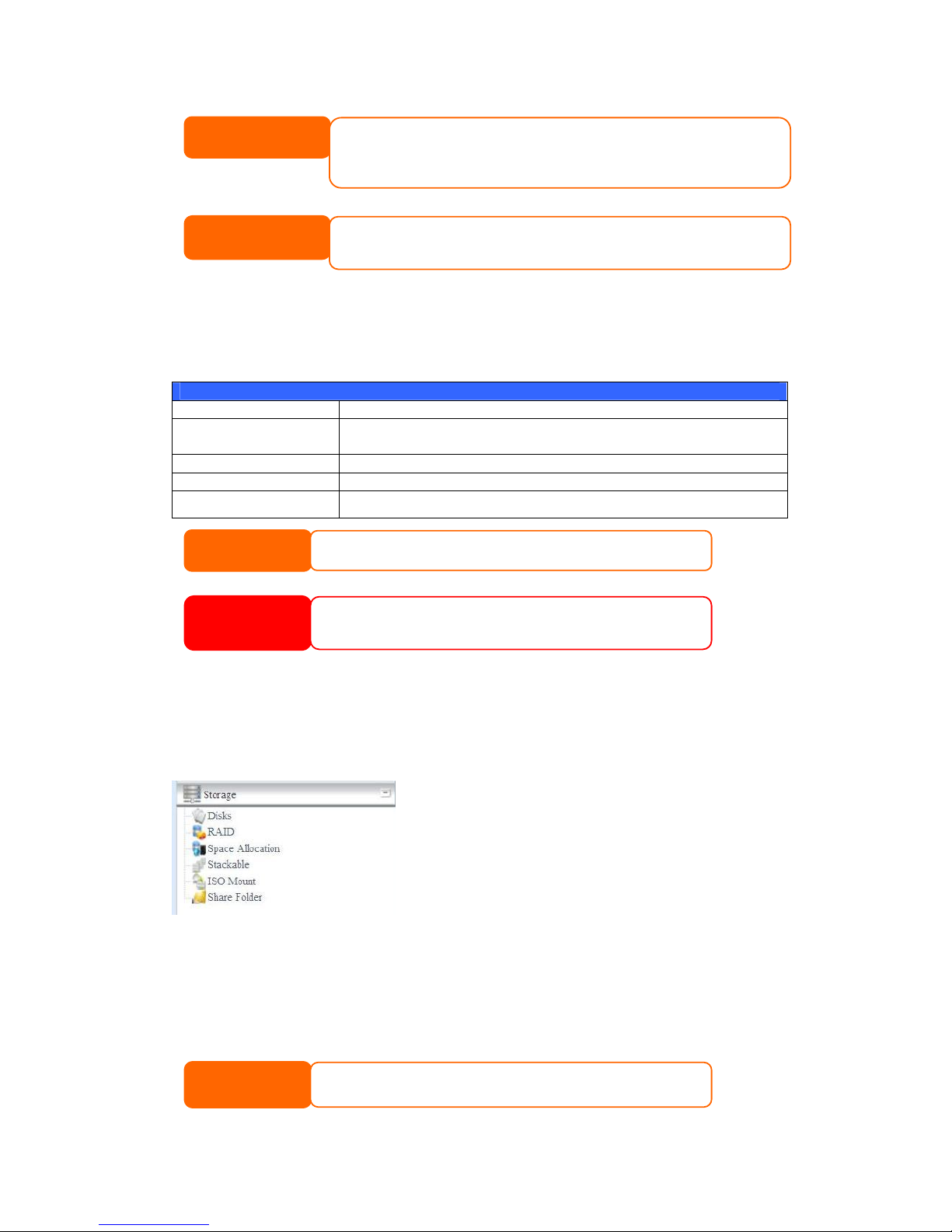
75
DHCP Server Configuration(For the N8900)
A DHCP server can be configured to assign IP addresses to devices connected to the
LAN3 port. To configure these ports, choose Additional LAN3 Configuration from
the System Network menu.
DHCP Configuration
Item Description
DHCP Server Enable or disable the DHCP server to automatically assign IP
address to PCs connected to the LAN3 interface.
Lowest IP in Range Specifies the starting IP address of the DHCP range.
Highest IP in Range Specifies the ending IP address of the DHCP range.
DNS Server Displayed the DNS server IP address.
Storage Management
The Storage menu displays the status of storage devices installed in the Thecus IP
storage, and includes storage configuration options such as RAID and disk settings,
folder configuration, space allocation and ISO Mount.
Disks Information
From the Storage menu, choose the Disks item and the Disks Information
screen appears. From here, you can see various items about installed SATA hard
disks. Blank lines indicate that a SATA hard disk is not currently installed in that
particular disk slot.
NOTE
• The screen shot below just example from Thecus IP Storage. The disk
slots can from 4 to 8 depend on the model of Thecus IP storage.
NOTE
Before enabling Jumbo Frame Support, please make sure your network equipment
supports Jumbo Frame. If your equipment is incompatibl e, you might not be able to
connect to your Thecus IP storage.
NOTE
The IP Segment of WAN/LAN1, LAN2 and LAN3 should not overlap.
WARNING
The IP address of the LAN3 interface should not be in the range of the
Start IP address and End IP address.
NOTE
If the IP sharing mode setting is set to “Enable” under WAN/LAN1 port, then this 2nd
gateway cannot be configured.
Page 76
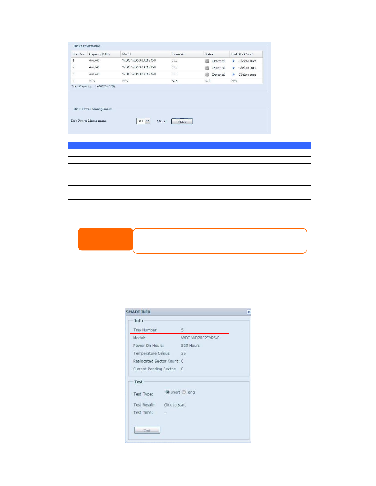
76
Disks Information
Item Description
Disk No. Indicates disk location.
Capacity Shows the SATA hard disk capacity.
Model Displays the SATA hard disk model name.
Firmware Shows the SATA hard disk firmware version.
Status Indicates the status of the disk. Can read OK, Warning, or
Failed.
Bad Block scan Yes to start scan Bad Block.
Total Capacity Shows the total SATA hard disk capacity.
Disk Power
Management
The administrator can set the disk to power down after a period of
inactivity.
S.M.A.R.T. Information
On the Disks Information screen, the status of each disk will be displayed in the
Status column. Clicking on an OK or Warning link will display the S.M.A.R.T
Information window for that particular disk.
You may also perform disk SMART test, simply to click “Test” to start with. The
result is only for reference and system will not take any action from its result.
NOTE
When the Status shows Warning, it usually means there are bad sectors on the
hard disk. It is shown only as a p recaution and you should consider changing the
drives.
Page 77

77
S.M.A.R.T. Information
Item Description
Tray Number Tray the hard disk is installed in.
Model Model name of the installed hard disk.
Power ON Hours
Count of hours in power-on state. The raw value of this attribute
shows total count of hours (or minutes, or seconds, depending on
manufacturer) in power-on state.
Temperature Celsius The current temperature of the hard disk in degrees Celsius
Reallocated Sector
Count
Count of reallocated sectors. When the hard drive finds a
read/write/verification error, it marks this sector as "reallocated"
and transfers data to a special reserved area (spare area).
This process is also known as remapping and "reallocated" sectors
are called remaps. This is why, on a modern hard disks, you can
not see "bad blocks" while testing the surface - all bad blocks are
hidden in reallocated sectors. However, the more sectors that are
reallocated, the more a decrease (up to 10% or more) can be
noticed in disk read/write speeds.
Current Pending Sector
Current count of unstable sectors (waiting for remapping). The
raw value of this attribute indicates the total number of sectors
waiting for remapping. Later, when some of these sectors are read
successfully, the value is decreased. If errors still occur when
reading sectors, the hard drive will try to restore the data, transfer
it to the reserved disk area (spare area), and mark this sector as
remapped. If this attribute value remains at zero, it indicates that
the quality of the corresponding surface area is low.
Test Type Set short or long time to test.
Test Result Result of the test.
Test Time Total time of the test.
Bad Block Scan
On the Disks Information screen, you may also perform disk bad block scan,
simply to click “Click to start” to start with. The result is only for reference and
system will not take any action from its result.
NOTE
If the Reallocated Sector Count > 32 or Current Pending Sector of a hard disk
drive > 0 , the status of the disk will show “Warning”. This warning is only used
to alert the system administrator that there are bad sectors on the disk, and
they should replace those disks as soon as possible.
Page 78

78
The testing result will be stay till system reboot with “Yet to start” displayed as
default.
RAID Information
From the Storage menu, choose the RAID item and the RAID Information screen
appears.
This screen lists the RAID volumes currently residing on the Thecus IP storage. From
this screen, you can get information about the status of your RAID volumes, as well
as the capacities allocated for data, and iSCSI. There is also a graph which
represents how the RAID volume is currently allocated.(The N8900 does not display
a pie chart.)
Please refer the N8900 RAID Management Information screenshot as below:
RAID Information
Item Description
Master RAID The RAID volume currently designated as the Master RAID
volume.
ID ID of the current RAID volume.
NOTE: All RAID IDs must be unique.
RAID Level Shows the current RAID configuration.
Status Indicates status of the RAID. Can read either Healthy,
Degraded, or Damaged.
Disks Used Hard disks used to form the current RAID volume.
Total Capacity Total capacity of the current RAID.
Data Capacity Indicates the used capacity and total capacity used by user data.
iSCSI Capacity Indicates the capacity allocated to iSCSI.
Page 79

79
Create a RAID
On the RAID Information screen, press the create button to go to the CREAT
RAID screen. In addition to RAID disk information and status, this screen lets you
make RAID configuration settings.
Using Create RAID, you can select stripe size, choose which disks are RAID disks or
the Spare Disk. .
RAID Configurations
Item Description
Disk No. Number assigned to the installed hard disks.
Capacity (MB) Capacity of the installed hard disks.
Model Model number of the installed hard disks.
Status Status of the installed hard disks.
Used If this is checked, current hard disk is a part of a RAID volume.
Spare If this is checked, current hard disk is designated as a spare for a
RAID volume.
Master RAID Check a box to designate this as the Master RAID volume. See the
NOTE below for more information.
Stripe Size This sets the stripe size to maximize performance of sequential
files in a storage volume. Keep the 64K setting unless you require
a special file storage layout in the storage volume. A larger stripe
size is better for large files.
Data Percentage The percentage of the RAID volume that will be used to store data.
Create Press this button to configure a file system and create the RAID
storage volume.
To create a RAID volume, follow the steps below:
1. On the RAID Information screen, click create.
2. On the RAID Configuration screen, set the RAID storage space as JBOD,
RAID 0, RAID 1, RAID 5, RAID 6, or RAID 10 (N8900 support RAID 50
and RAID 60)— see Appendix B: RAID Basics for a detailed description of
each.
3. Specify a RAID ID.
4. If this RAID volume is meant to be the Master RAID volume, tick the Master
RAID checkbox.
5. Selected whether the RAID volume will be encrypted or not.
The RAID volume can protect data by using RAID Volume Encryption
function to prevent the risk of data exposure. To activate this function, the
Encryption option needs to be enabled while the RAID is created and
followed by password input for identification. Also, an external writable USB
disk plugged into any USB port on the system is required to save the
password you have entered while the RAID volume is being created. See the
screenshot below for details.
NOTE
In a multiple RAID configuration, one RAID volume must be designated as the
Master RAID vol ume. The Master RAID volume will store all installed modules. If
the Master RAID is changed to another location (i.e. assigning volume 2 to be
the Master RAID volume after volume 1 had been previously assigned), then all
modules must be reinstalled. In addition, all system folders that were contained
on the Master RAID volume will be invisible. Reassigning this volume to be the
Master RAID will make these folders visible again.
Page 80

80
Once the Create button has been pressed with the Encryption checkbox
enabled, the following message pop-up will appear for confirmation.
After the RAID volume has been created, you may remove this USB disk until
the next time the system boots. The RAID volume can not be mounted if the
USB disk with key can not be found in any system USB port when the volume
is accessed. To activate the encrypted volume, plug the USB disk containing
the encryption key and into any system USB port.
We are strongly recommended copying the RAID volume encryption key to a
safe place. You can find the encryption key file from the USB disk in the
following format:
(RAID volume created date)_xxxxxx.key
RAID volumes with encryption enabled will be displayed with a key lock symbol next
to volume ID name.
NOTE
1. With RAID volume encryption enabled, the system performance will
goes down.
2. With RAID volume encryption enabled, RAID volume expansion will
operated in off line mode.
WARNING
Please keep USB disk in a safe place and also backup the encrypted key.
There is no way to rescue data back if the key
is lost.
Page 81

81
6. Specify a stripe size — 64K is the default setting.
7. Specify the percentage allocated for user data by drag the horizontal bar.
The remaining space will be made available for iSCSI.
8. Selected the file system you like to have for this RAID volume. The selection
is available from ext3, XFS and ZFS. N8900 support ext3, XFS and ext4.
9. Press Create to build the RAID storage volume.
NOTE
.Select ZFS file system while snapshot is needed. It is only one ZFS file system
allowed to be created per system.
.ZFS file system is only accessibl e by CIFS/SMB, not for AFP and NFS users.
.XFS file system is not support fol der quota feature
Page 82

82
With a RAID 1, RAID 5, or RAID 6 volume, you can also add a spare disk after the
RAID is created.
See Chapter 6: Tips and Tricks > Adding a Spare Disk for details.
For more information on RAID, see Appendix B: RAID Basics.
RAID Level
You can set the storage volume as JBOD, RAID 0, RAID 1, RAID 5, RAID 6 or
RAID 10, (N8900 support RAID 50 and RAID 60). RAID configuration is usually
required only when you first set up the device. A brief description of each RAID
setting follows:
RAID Levels
Level Description
JBOD The storage volume is a single HDD with no RAID support. JBOD
requires a minimum of 1 disk.
RAID 0 Provides data striping but no redundancy. Improves performance
but not data safety. RAID 0 requires a minimum of 2 disks.
RAID 1 Offers disk mirroring. Provides twice the read rate of single disks,
but same write rate. RAID 1 requires a minimum of 2 disks.
NOTE
Building a RAID volume may take time, depending on the size of hard drives
and RAID mode. In g eneral, while the RAID volume building process is up to
“RAID Building” then the data volume is capable to be accessed.
WARNING
Creating RAID destroys all data in the current RAID volume. The data is
unrecoverable.
Page 83

83
RAID 5 Data striping and stripe error correction information provided.
RAID 5 requires a minimum of 3 disks. RAID 5 can sustain one
failed disk.
RAID 6 Two independent parity computations must be used in order to
provide protection against double disk failure. Two different
algorithms are employed to achieve this purpose. RAID 6 requires
a minimum of 4 disks. RAID 6 can sustain two failed disks.
RAID 10 RAID 10 has high reliability and high performance. RAID 10 is
implemented as a striped array whose segments are RAID 1
arrays. It has the fault tolerance of RAID 1 and the performance of
RAID 0. RAID 10 requires 4 disks. RAID 10 can sustain two failed
disks.
RAID 50(N8900) RAID 50 combines the straight block-level striping of RAID 0 with
the distributed parity of RAID 5. This is a RAID 0 array striped
across RAID 5 elements. It requires at least 6 drives.
RAID 60(N8900) RAID 60 combines the straight block-level striping of RAID 0 with
the distributed double parity of RAID 6. That is, a RAID 0 array
striped across RAID 6 elements. It requires at least 8 disks.
Edit RAID
On the RAID Information screen, press the Edit button to go to the RAID
Information screen.
Using Edit RAID, you can select RAID ID and the Spare Disk. .
WARNING
If the administrator improperly removes a hard disk that should not be
removed when RAID status is degraded, all data will be lost.
Page 84

84
Remove RAID
Click to remove the RAID volume. All user data and iSCSI has been created in
selected RAID volume will be removed.
To remove a RAID volume, follow the steps below:
1. On the RAID List screen, select the RAID volume by clicking on its radio
button, and click RAID Information to open the RAID Configuration
screen.
2. On the RAID Configuration screen, click Remove RAID.
3. The confirmation screen appear, you will have to input “Yes” with exactly
wording case to complete “Remove RAID” operation
WARNING
Remove RAID destroys all data in the current RAID volume. The data is
unrecoverable.
Page 85

85
Expanding a RAID
To expand a RAID 1, RAID 5, or RAID 6 volume, follow the steps below:
1. Replace one of the hard drives in the RAID volume and allow it to
automatically rebuild.
2. Once rebuilt, you can continue to replace any remaining disks in the RAID
array.
3. When you are done replacing hard drives, log on to Web Management.
Navigate to Storage> RAID to open the RAID Configuration screen.
4. On the RAID Information screen, and click Edit to open the RAID
Configuration screen.
5. On the RAID Configuration screen, click Expand.
Migrating a RAID
Once a RAID volume has been created, you may want to move it to other physical
drives or change the RAID array all together. To migrate a RAID 0, RAID 1, RAID 5
or RAID 6 volume, follow the steps below:
1. From the RAID Configuration screen, click Migrate RAID.
2. A list of possible RAID migration configurations will be listed. Select the
desired migration scheme and click Apply.
3. The system will begin migrating the RAID volume.
NOTE
RAID expansion did not support fil e system created by ZFS.
Page 86

86
With RAID level migration function, the limitation as listed below.
1. During RAID level migration, it is not allowed reboot or shutdown system.
2. The RAID migration from R1 to R5 or R1 to R6, the all services will restart
and volumes “iSCSI” is read only but “user data” is capable read / write
during operation.
NOTE
Migrating a RAID volume could take several hours to complete
NOTE
The migr
ation scheme below
is based on Thecus
IP
Storage series products in maximum possible
combination. The other model which has less HDD
supported can refer web UI while RAID migration
operated.
Page 87

87
Below is a table listing of possible RAID migration schemes:
To
From
RAID 0 RAID 5 RAID 6
RAID 1 [RAID 1] HDDx2 to [RAID 5] HDDx3
[RAID 1] HDDx2 to [RAID 5] HDDx4
[RAID 1] HDDx2 to [RAID 5] HDDx5
[RAID 1] HDDx2 to [RAID 5] HDDx6
[RAID 1] HDDx2 to [RAID 5] HDDx7
[RAID 1] HDDx2 to [RAID 5] HDDx8
………………………………..HDDx16
[RAID 1] HDDx3 to [RAID 5] HDDx4
[RAID 1] HDDx3 to [RAID 5] HDDx5
[RAID 1] HDDx3 to [RAID 5] HDDx6
[RAID 1] HDDx3 to [RAID 5] HDDx7
[RAID 1] HDDx3 to [RAID 5] HDDx8
………………………………..HDDx16
[RAID 1] HDDx4 to [RAID 5] HDDx5
[RAID 1] HDDx4 to [RAID 5] HDDx6
[RAID 1] HDDx4 to [RAID 5] HDDx7
[RAID 1] HDDx4 to [RAID 5] HDDx8
………………………………..HDDx16
[RAID 1] HDDx5 to [RAID 5] HDDx6
[RAID 1] HDDx5 to [RAID 5] HDDx7
[RAID 1] HDDx5 to [RAID 5] HDDx8
………………………………..HDDx16
[RAID 1] HDDx6 to [RAID 5] HDDx7
[RAID 1] HDDx6 to [RAID 5] HDDx8
………………………………..HDDx16
[RAID 1] HDDx7 to [RAID 5] HDDx8
………………………………..HDDx16
[RAID 1] HDDx2 to [RAID 6] HDDx4
[RAID 1] HDDx2 to [RAID 6] HDDx5
[RAID 1] HDDx2 to [RAID 6] HDDx6
[RAID 1] HDDx2 to [RAID 6] HDDx7
[RAID 1] HDDx2 to [RAID 6] HDDx8
………………………………..HDDx16
[RAID 1] HDDx3 to [RAID 6] HDDx4
[RAID 1] HDDx3 to [RAID 6] HDDx5
[RAID 1] HDDx3 to [RAID 6] HDDx6
[RAID 1] HDDx3 to [RAID 6] HDDx7
[RAID 1] HDDx3 to [RAID 6] HDDx8
………………………………..HDDx16
[RAID 1] HDDx4 to [RAID 6] HDDx5
[RAID 1] HDDx4 to [RAID 6] HDDx6
[RAID 1] HDDx4 to [RAID 6] HDDx7
[RAID 1] HDDx4 to [RAID 6] HDDx8
………………………………..HDDx16
[RAID 1] HDDx5 to [RAID 6] HDDx6
[RAID 1] HDDx5 to [RAID 6] HDDx7
[RAID 1] HDDx5 to [RAID 6] HDDx8
………………………………..HDDx16
[RAID 1] HDDx6 to [RAID 6] HDDx7
[RAID 1] HDDx6 to [RAID 6] HDDx8
………………………………..HDDx16
[RAID 1] HDDx7 to [RAID 6] HDDx8
………………………………..HDDx16
RAID 5 X [RAID 5] HDDx3 to [RAID 5] HDDx4
[RAID 5] HDDx3 to [RAID 5] HDDx5
[RAID 5] HDDx3 to [RAID 5] HDDx6
[RAID 5] HDDx3 to [RAID 5] HDDx7
[RAID 5] HDDx3 to [RAID 5] HDDx8
………………………………..HDDx16
[RAID 5] HDDx4 to [RAID 5] HDDx5
[RAID 5] HDDx4 to [RAID 5] HDDx6
[RAID 5] HDDx4 to [RAID 5] HDDx7
[RAID 5] HDDx4 to [RAID 5] HDDx8
………………………………..HDDx16
[RAID 5] HDDx5 to [RAID 5] HDDx6
[RAID 5] HDDx5 to [RAID 5] HDDx7
[RAID 5] HDDx5 to [RAID 5] HDDx8
………………………………..HDDx16
[RAID 5] HDDx6 to [RAID 5] HDDx7
[RAID 5] HDDx6 to [RAID 5] HDDx8
………………………………..HDDx16
[RAID 6] HDDx7 to [RAID 6] HDDx8
………………………………..HDDx16
X
Page 88

88
RAID 6 X X [ONLINE]
[RAID 6] HDDx4 to [RAID 6] HDDx5
[RAID 6] HDDx4 to [RAID 6] HDDx6
[RAID 6] HDDx4 to [RAID 6] HDDx7
[RAID 6] HDDx4 to [RAID 6] HDDx8
………………………………..HDDx16
[RAID 6] HDDx5 to [RAID 6] HDDx6
[RAID 6] HDDx5 to [RAID 6] HDDx7
[RAID 6] HDDx5 to [RAID 6] HDDx8
………………………………..HDDx16
[RAID 6] HDDx6 to [RAID 6] HDDx7
[RAID 6] HDDx6 to [RAID 6] HDDx8
………………………………..HDDx16
[RAID 6] HDDx7 to [RAID 6] HDDx8
………………………………..HDDx16
Space Allocation
iSCSI Target
You may specify the space allocated for iSCSI or target USB volumes (target USB is
available in model N5500 and 1U4600). The iSCSI volume can be created from 2 to
25 volumes per system depend on Thecus IP storage’s model.
Model N4100PRO N0503
N3200XXX
N4200
series
N2200XXX
N5200XXX
1U4200XXX
N8200XXX
N5500
1U4600
N7700
N7700+
N8800
N8800+
N7700PRO
N7700SAS
N8800PRO
N8800SAS
N8900
Allow
iSCSI
volume
2 5 10 10 15 25
To do this, under the Storage menu, click RAID and the RAID List window
appears. Select the RAID volume you wish to reallocate by clicking on its radio
button, and click Space Allocation. The RAID Information and Volume
Allocation List windows will appear.
The Volume Allocation List displays the space allocated for iSCSI volumes on the
current RAID volume.
Page 89

89
Volume Allocation List
Item Description
Modify Click this to modify the allocated space.
Delete Click this to delete the allocated space.
iSCSI Target Click to allocate space to iSCSI volume.
Type Type of volume. Can be either USB or iSCSI.
Name Name assigned to the volume.
Capacity Capacity of the allocated space.
Allocating Space for iSCSI Volume
Page 90

90
To allocate space for an iSCSI volume on the current RAID volume, follow the steps
below:
1. Under the Volume Allocation List, select iSCSI Target then click Add.
The Create iSCSI Volume screen appears.
Create iSCSI Volume
Item Description
RAID ID ID of current RAID volume.
Allocation Percentage and amount of space allocated to iSCSI volume.
Unused Percentage and amount of unused space on current RAID
volume.
iSCSI Target Volume Enable or Disable the iSCSI Target Volume.
Target Name Name of the iSCSI Target. This name will be used by the
Stackable NAS function to identify this export share.
Year Select the current year from the dropdown.
Authentication You may choose CHAP authentication or choose None.
Month Select the current month from the dropdown.
LUN ID Specific Logic unit ID number.
Username Enter a username.
Password Enter a password.
Password Confirm Reenter the chosen password
2. Designate the percentage to be allocated from the Allocation drag bar.
3. Enable the iSCSI Target Service by selecting Enable.
4. Choose to enable CHAP authentication or choose None.
5. Enter a Target Name. This will be used by the Stackable NAS function to
identify this export share.
6. Choose the current year from the Year dropdown.
7. Choose the current month from the Month dropdown.
Page 91

91
8. When iSCSI target volume has been created, the LUN ID is configurable from
1 to 254 with a default of the next available number in ascending numerical
order. The LUN ID is unique and can not be duplicated except for LUN ID 0.
9. If you’ve enabled CHAP authentication, enter a username and a password.
Confirm your chosen password be reentering it in the Password Confirm
box.
10. Click OK to create the iSCSI volume.
Modify iSCSI Volume
To Modify iSCSI volume on the current RAID volume, follow the steps below:
1. Under the Volume Allocation List, click Modify.
The Modify iSCSI Volume screen appears.
2. Modify your setting. Press ok to change.
Page 92

92
Expand Volume
The iSCSI volume is now able to expand its capacity from unused space. From the
volume list, simply select the iSCSI volume you like to expand and click the Expand
button:
You will then see the dialog box displayed below. Drag the Expand Capacity bar to
the size you want. Then press Expand to confirm the operation.
Delete Volume
To delete volume on the current RAID volume, follow the steps below:
1. Under the Volume Allocation List, click Delete.
The Space Allocation screen appears.
Page 93

93
2. Press YES. All data in the volume will be removed.
iSCSI Thin-Provisioning
With this function, the iSCSI capacity can be more flexible and more efficiently serve
more users.
The idea for iSCSI thin-provisioning is sharing the available physical capacity to a
number of iSCSI target volumes and also setup virtual capacity to expand the
physical size while it needed.
To setup iSCSI thin-provisioning, go to Space Allocation under the Storage
category. The iSCSI thin-provisioning volume needs to be created first. Simply click
iSCSI Thin-Provision Target. You can refer the screen shot below.
Page 94

94
Next, setup the physical capacity for iSCSI thin-provision volume by dragging the
Allocation bar to the desired size.
After the size has been determined, click OK to confirm. Now you will see the iSCSI
thin-provisioning volume is available from the list. Please refer to the screenshot
below.
Page 95

95
Now you can start to create iSCSI targets to join the newly-created iSCSI
thin-provision volume. Basically, the iSCSI target under iSCSI thin-provisioning has
exactly same settings screen as the standard iSCSI target volume creation. The only
difference is the “Virtual Size” of capacity.
Unlike creating standard iSCSI target volumes, the capacity has been physically
allocated. The iSCSI target volume creation under thin-provisioning can virtually be
up to 16000GB (16TB).
Let’s take the example below:
1. The physical size for the iSCSI thin-provision volume is 333.88GB. You can refer
the screenshot above.
2. The iSCSI target volume under thin-provisioning starts with 333.38GB in
physical size and you may use drag the Virtual Size bar to select the desired
virtual size. The maximum virtual size is 16000GB.
3. In this case, if you make the iSCSI target volume 1700GB, then the virtual size
is available for the next iSCSI target volume under thin-provisioning is 14300GB
(16000-1700).
4. The limit is 5 iSCSI target volumes under thin-provisioning or a virtual size of
16000GB.
iSCSI Thin-provision physical size starts with 333.8GB
The virtual capacity is limited to 16000GB
Page 96

96
The screen shot for iSCSI target volume creation under thin-provisioning; the
physical capacity 333.8GB.
The screen shot to setup an iSCSI target volume under thin-provisioning of 1700GB.
iSCSI target volume creation. The maximum virtual size is 14300GB (16000GB –
1700GB(1st iSCSI target volume)).
This screenshot lists iSCSI target volumes created under thin-provisioning. The 2nd
iSCSI target volume under thin-provisioning has been created with a capacity of
14300GB.
Page 97

97
This message appears if there is no more room for new iSCSI target creation.
Advance Option
There are 2 options is currently allow Admin to Enable/Disable to operate Thecus IP
storage associated with iSCSI setting. The details as listed in following screenshot.
With the option changed, it will need to reboot system to activate.
NOTE
1. Each RAID volume can only create one iSCSI thin-provision volume.
2. Each thin-provision volume can only create 5 iSCSI target volumes.
3. The notification will send out while the physical size of iSCSI
thin-provision capacity has used up to 90%.
Page 98

98
iSCSI Block Size
Select the block size with 4K while the iSCSI volume size is over 2TB.
iSCSI CRC/Checksum
To enable this option, the initiator can connect with “Data digest” and “Header
digest” enabled.
iSCSI(For the N8900)
You may specify the space allocated for iSCSI. The iSCSI target can be created total
25 volumes per system of N8900.
Page 99

99
iSCSI Target
To add iSCSI target volume, click iSCSI with associated RAID volume from its drop
down list to select desired RAID volume.
iSCSI Target
Item Description
Add Click to allocate space to iSCSI target from associated RAID
volume.
Modify Click this to modify the iSCSI Target.
Advanced There are 3 options (iSCSI CRC/Checksum, Max
Connections, Error Recovery Level) is currently allow Admin
to Enable/Disable to operate Thecus IP storage associated
with iSCSI setting.
Delete Click this to delete the iSCSI Target.
Allocating Space for iSCSI Volume
To allocate space for an iSCSI target on the current RAID volume, follow the steps
below:
1. Under the iSCSI Target List, select iSCSI Target then click Add.
The Create iSCSI Volume screen appears.
Page 100

100
Create iSCSI Volume
Item Description
iSCSI Target Volume Enable or Disable the iSCSI Target Volume.
Target Name Name of the iSCSI Target. This name will be used by the
Stackable NAS function to identify this export share.
iqn_Year Select the current year from the dropdown.
Iqn_Month Select the current month from the dropdown.
Authentication You may choose CHAP authentication or choose None.
Username Enter a username.
Password Enter a password.
Password Confirm Reenter the chosen password
Mutual CHAP With this level of security, the target and the initiator
authenticate each other.
Username Enter a username.
Password Enter a password.
Password Confirm Reenter the chosen password
RAID ID ID of current RAID volume.
LUN Allocation Two modes can be choose from:
Thin-provision:iSCSI thin-provisioning is sharing the
available physical capacity to multiple iSCSI target
volumes creation. And allowed virtual capacity be
assigned in prior then added physical space while it
has run out.
Instant Allocation : Allocate available physical
capacity to iSCSI target volumes.
LUN Name Name of the LUN.
Unused Unused space on current RAID volume.
Allocation Percentage and amount of space allocated to iSCSI volume.
LUN ID Specific Logic unit ID number.
 Loading...