

The Corner Fridge THERMOLUX TL6, THERMOLUX TL10, THERMOLUX TL16 Installation And Operation Instructions Manual
CORNER FRIDGE
THERMOLUX TL6 - TL10 - TL16
INSTALLATION AND
OPERATION INSTRUCTIONS
DEFYING
CONVENTION

Contents
Check-list before installation 2
Important Information 3
Things You Should Know 3
General 3
Usage 4
Guarantee 4
Trade purchases 4
Technical specifications 5
Extra Equipment 5
Winter Operation 5
Installation of Thermolux TL6-10-16 cooling unit 6
Alt 1. Self assembly cooling room with plastic cover 7
Alt 2. Self assembly cooling room with louvre grilles directly behind cooling unit 8
Alt 3. Self assembly cooling room with louvre grilles at the floor and ceiling level 9
Alt 4. Self assembly cooling room with vertical louvre grilles to the side 10
Alt 5. Element cooling room, free-standing 11
Alt 6. Element cooling room with louvre grilles 12
Start-up and commissioning 13
Simple troubleshooting 13
Cleaning and maintenance 14
Component Diagram 14
Connection Diagram 15

3
Important Information
Things You Should Know
Please check the following points before installation
> The unit must stand upright for 2-3 hours before starting, so that the oil can drain back into
the compressor.
> Remove the polystyrene packaging from the front of the compressor.
> Check that the copper pipe is not in contact with any metal or plastic; this also applies to the loop in the plastic
vessel.
> Make sure that drainage tube lies down in the evaporation vessel.
> Push in the power plug, and check that both the fans and the compressor are operating normally.
General
> The cooling units are available in 3 models with different cooling capacity based on a room volume of up to 17,000
litres. In addition to the size of the cooling room, consideration must always be given to the cooling capacity in relation
to traffic and product introduction.
> Thermolux cooling units are installed from the cooling room side through the cooling room wall to the warm side. This
offers much greater flexibility with regard to alternative installation solutions.
> The cooling units are dimensioned for cooling food products for private use.
> A stable, correct cooling room temperature is dependent on correct insulation in the floor/ceiling/walls, and on the
ambient temperature on the warm side of the cooling room not exceeding an average temperature of 27°C.
> Let the cooling unit remain installed on the wall for about 2 hours before it is started. This will allow the oil to drain
back into the compressor after transport and handling.
> It is important for the cooling unit to have a good supply of fresh air, and for the room into which it installed to be well
ventilated. In the case of installation with a small distance from the warm side of the unit to the opposite wall/ceiling,
a physical barrier must always be installed between the inlet to and exhaust from the fan, so that the warm air is led
away and replaced by cooler air to the unit.
> The cooling unit requires a voltage of 220-240V and a 10A earthed plug as a minimum.
> The contact for the cooling unit can be installed on either the warm or the cold side.
> This must be taken into account when a contact is positioned inside a cover or louvre grille.

4
Usage
> Thermolux Cooling Units are designed for normal use in private households.
> If the product is used for a purpose other than the envisaged application, this may require other approvals
from the local electricity authority for the location.
> In order to ensure that the product has a long service life, it is important to adhere closely to the
installation and operating instructions.
> Corner Fridge Co does not accept responsibility for unreported transport damage or incorrect installation.
> Even under normal use, maintenance such as cleaning of the condenser/dust filter and fans is required.
> The fan motor, compressor parts and starting equipment are components that are exposed to wear and
may have a variable service life depending on the environment and maintenance, and they may require
replacement.
> The guarantee period is 2 years from the date of purchase.
> The supplier/producer shall have the right to repair the product within the time limits stipulated in the
Sale of Goods Act, and by the most expedient means.
> The serial number of the cooling unit can be found on the rating plate at the bottom left of the
compressor, and this must be stated in the event of a claim.
Guarantee
> Electrical components/wearing parts such as thermostats, fan motors, starting equipment, lamps/bulbs
and the like are guaranteed or can be the subject of a claim for a period of 2 years from the date of
purchase or serial number. These are so-called wearing parts, which have a variable service life depending
on maintenance and the environment.
> Leaks in the system or a defective compressor, evaporator, condenser, and other components that are
intended to have a long service life under normal conditions of wear and use, are covered for 5 years
from the date of purchase.
> Any faults that are attributable to a defective fan motor are covered under the 2-year rule.
Trade purchases
> Trade purchases include everything that is not a consumer purchase, for example if the product is installed
in a business, café, institution, nursery, catering establishment, etc.
> The right to make a claim in this case applies for 2 years, and the guarantee on wearing parts is 1 year
under the terms of the Sale of Goods Act.

5
Technical specifications
Model TL6 TL10 TL16
External dimensions WxDxH
480x230x790 480x230x790 480x230x790
Aperture in wall WxH
440x740 440x740 440x740
Refrigerant
R134A CFC-free 0.29 kg R134A CFC-free 0.30 kg R134A CFC-free 0.39 kg
Voltage
220-240V AC 50 Hz 220-240V AC 50 Hz 220-240V AC 50 Hz
Compressor
Danfoss FR8.5G Danfoss FR10G Danfoss SC15G
Cooling effect
8000 litres/390 W 12000 litres/450 W 17000 litres/780 W
Thermostat setting
3-12°C 3-12°C 3-12°C
Ambient temperature
10-27°C 10-27°C 10-27°C
Net weight
23 kg 24 kg 26 kg
Dust filter
Yes Yes No
Evaporation of condensation
water
Yes Yes
No, added to wastewater/
holding tank
Timer for defrosting
No Yes Yes
Extra equipment:
> Louvre grilles > Warm cable/pressure switch (winter operation)
> Plastic cover > Insulation sleeve - Air barrier (foam strip
> LED lamp with photo cell
Winter operation:
Winter operation is mandatory for installation in an external wall.
> Air barrier (foam strip)
> 2x Grilles for cooling air
> 1x Cover for cooling air (alternative to grilles)
NB! The cover must be installed on a wall with a full opening below/above.
> 1x insulating sleeve for sealing against the cooling unit and recess in the wall
(taped/pinned in place):
> LED lamp (pre-wired) - Extra equipment

6
Installation of Thermolux TL6-10-16 cooling unit
The cooling unit gives off heat to the room adjoining the cooling room
Installation can be done in several alternative ways; decide which alternative suits you best, and
adhere closely to the installation instructions.
> Alternative 1 - Self-assembly cooling room with plastic cover.
> Alternative 2 - Self-assembly cooling room with louvre grilles directly behind the cooling unit.
> Alternative 3 - Self-assembly cooling room with louvre grilles at floor and ceiling level.
> Alternative 4 - Self-assembly cooling room with vertical louvre grilles to the side.
> Alternative 5 - Element cooling room, free-standing.
> Alternative 6 - Element cooling room with louvre grilles.
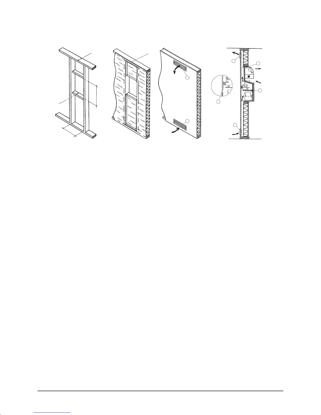
Alternative 1
3
Alternative 2
1
2
Alternative 3
2
1
Alternative 4

7
1. Make a W440xH740 hole in the wall, as shown in the figure.
2. Secure the insulating sleeve around the inside of the opening into the cooling room with pins or tape.
3. Review the check-list on page 2.
4. The electrical connection with the power cord for the plug socket can be routed on the warm or cold side. If the cord
exits on the top edge of the cover on the outside of the cooling room, the power cord must be secured in such a way
that it is not able to fall down into the fan.
If the contact is to be located inside the cooling room, the power cord is routed at the bottom in the corner, and it is
secured with a clip so that it is not trapped under the unit. The corner of the unit is rounded, so that there is plenty of
space for the power cord innermost in the corner of the unit housing. Cut out a little track for the power cord in the
flange on the unit so that the power cord does not become trapped.
5. Lift in the unit from the cooling room side and screw the cooling unit securely (but not hard) at each corner until the
gasket seals tightly against the wall on all edges.
6. Fit an air barrier (foam rubber) to the cooling unit behind the fan. Make sure that it projects approx. 10 mm outside the
wall, so that it lies with slight pressure against the depression in the plastic cover. See the sectional drawing, item 3.
(This is important for the service life of the unit and for the guarantee to be valid).
7. Secure the air barrier with a screw to the upright on each side.
8. Screw the cover securely to the wall, and not to the unit. Make sure that the depression in the plastic cover touches the
air barrier. The entire air gap above and below the air barrier behind the plastic cover must be open in order to ensure
an unobstructed air flow.
9. TL16 does not have evaporation of the condensation water and therefore must be connected to a drain with the help of
a hose. The dimension of the hose should be 10 mm internally; the hose is not supplied. It is connected to a pipe stub
on the bottom edge of the cooling unit on the cooling room side. (Not applicable to TL6 and TL10).
10. Connect the power cord and check that the unit is operating as intended.
Cleaning methods and range for this alternative are very good
100
100
440
740
3
3
3
4
Plastic cover
Sectional drawing
With a large plastic cover
Framework Seen from the
warm side
3. Air barrier
4. Dust filter
Insulation and
moisture barrier
Seen from the
warm side
Alt. 1 - Self-assembly cooling room with plastic cover
IMPORTANT!

8
1. Make a W440xH740 recess in the wall on the cooling room side, as shown in the figure. Keep the plasterboard/
chipboard panel on the outside of the cooling room.
2. Make a W420xH110 cut-for ventilation grilles in the plasterboard/chipboard panel on the outside of the cooling room at
the top and at the bottom in the recess.
3. Fit an air barrier (foam rubber) against the chipboard/plasterboard panel between the uprights. It must be 80 mm
narrower than the wall thickness.
4. Secure the air barrier, 250 mm from the bottom of the recess with screws on either side of the upright so that it is held
tightly between the chipboard/plasterboard panel and the broad field on the plastic cover for the fan. See the sectional
drawing, item 3. (This is important for the service life of the unit and for the guarantee to be valid).
5. Secure the insulating sleeve around the inside of the opening into the cooling room with pins or tape.
6. The electrical connection with the power cord for the plug socket can be routed on the warm or cold side. If the cord
exits on the top edge of the cooling unit on the outside of the cooling room, the power cord must be secured in such a
way that it is not able to fall down into the fan. If the contact is positioned inside the louvre grille, this must be marked.
If the contact is to be located inside the cooling room, the power cord is routed at the bottom in the corner, and it is
secured with a clip so that it is not trapped under the unit. The corner of the unit is rounded, so that there is plenty of
space for the power cord innermost in the corner of the unit housing. Cut out a little track for the power cord in the
flange on the unit so that the power cord does not become trapped.
7. Review the check-list on page 2.
8. Lift in the unit from the cooling room side and screw the cooling unit securely (but not hard) at each corner until the
gasket seals tightly against the wall on all edges.
9. Screw the lower ventilation grille securely in place with the vanes facing downwards, and the upper grille with the
vanes facing upwards.
10. TL16 does not have evaporation of the condensation water and therefore must be connected to a drain with the help
of a hose. The dimension of the hose should be 10 mm internally; the hose is not supplied. It is connected to a pipe
stub on the bottom edge of the cooling unit on the cooling room side. (Not applicable to TL6 and TL10).
11. Connect the power cord and check that the unit is operating as intended.
This alternative has a slightly higher noise level and can damped to some extent by lowering the lower grille by 20-30 cm
below the cooling unit, see alternative 3.
Alt. 2 - Self-assembly cooling room with louvre grilles directly behind
the cooling unit
150
1
00
100
440
740
1
2
3
1
5
4
3
2
100
440
Sectional drawing
Grilles behind the cooler
Framework
Seen from the warm side
1. Grille (vanes facing upwards)
2. Grille (vanes facing downwards)
3. Air barrier
Framework
Seen from the
warm side
4. Dust filter
5. Flange gasket
Grilles behind the
cooler
IMPORTANT!
9
Alt. 3 - Self-assembly cooling room with louvre grilles at floor and
ceiling level
3
150
100
150
440
740
2
1
2
5
4
1
IMPORTANT!
1. Make a W440xH740 recess in the wall on the side of the cooling room, as shown in the figure.
2. Position an air duct over and under the recess in the wall on the outside of the cooling room, as shown in the figure.
Min 50x440 mm.
3. Make a W420xH110 cut-for ventilation grilles in the plasterboard/chipboard panel on the outside of the cooling room at
the top and at the bottom in the air duct.
4. Fit an air barrier (foam rubber) to the chipboard/plasterboard panel between the uprights. It must be 80 mm narrower
than the wall thickness.
5. Secure the air barrier 250 mm from the bottom of the recess with screws on either side of the upright so that it is held
tightly between the chipboard/plasterboard panel and the broad field on the plastic cover for the fan. See the sectional
drawing, item 3. (This is important for the service life of the unit and for the guarantee to be valid).
6. Secure the insulating sleeve around the inside of the opening into the cooling room with pins or tape.
7. The electrical connection with the power cord for the plug socket can be routed on the warm or cold side. If the contact
is to be located inside the cooling room, the power cord is routed at the bottom in the corner, and it is secured with a
clip so that it is not trapped under the unit. The corner of the unit is rounded, so that there is plenty of space for the
power cord innermost in the corner of the unit housing. Route the power cord in the depression in the slot/groove on
the panel, or cut a small notch in the flange.
8. Review the check-list on page 2.
9. Lift in the unit from the cooling room side and screw the cooling unit securely (but not hard) at each corner until the
gasket seals tightly against the wall on all edges.
10. Screw the lower ventilation grille securely in place with the vanes facing downwards, and the upper grille with the
vanes facing upwards.
11. TL16 does not have evaporation of the condensation water and therefore must be connected to a drain with the help
of a hose. The dimension of the hose should be 10 mm internally; the hose is not supplied. It is connected to a pipe
stub on the bottom edge of the cooling unit on the cooling room side. (Not applicable to TL6 and TL10).
12. Connect the power cord and check that the unit is operating as intended.
Alternatives 3 and 4 have the lowest noise level.
Sectional drawing
Grilles at floor and
ceiling level
Framework
Grilles at floor and ceiling level
1. Grille (vanes facing upwards)
2. Grille (vanes facing downwards)
Insulation and moisture
barrier Grilles at floor
and ceiling level.
3. Air barrier
4. Dust filter
Grilles at floor and
ceiling level

10
Alt. 4 - Self-assembly cooling room with vertical ventilation grilles to
the side
3
150
100
150
440
740
2
1
2
5
4
1
IMPORTANT!
1. Set up a parallel wall inside the cooling room wall from floor to ceiling with a min. 50 mm air gap in between. This
alternative can also be supplied ready-made from the factory. Make a W440xH740 recess in the wall on the cooling
room side, as shown in the figure.
2. Make a W70xH465 cut-for vertical ventilation grilles in the plasterboard/chipboard panel on the outside of the cooling
room at the top and at the bottom with an opening inside the gap between the walls.
3. Fit an air barrier (foam rubber), onto the chipboard/plasterboard between the uprights. It must be 80 mm narrower
than the wall thickness.
4. Secure the air barrier, 250 mm from the bottom of the recess with screws on either side of the upright so that it is held
tightly between the chipboard/plasterboard panel and the broad field on the plastic cover for the fan. See the sectional
drawing, item 3. (This is important for the service life of the unit and for the guarantee to be valid).
5. Secure the insulating sleeve around the inside of the opening into the cooling room with pins or tape.
6. The electrical connection with the power cord for the plug socket can be routed on the warm or cold side. If the contact
is to be located inside the cooling room, the power cord is routed at the bottom in the corner, and it is secured with a
clip so that it is not trapped under the unit. The corner of the unit is rounded, so that there is plenty of space for the
power cord innermost in the corner of the unit housing. Route the power cord in the depression in the slot/groove on
the panel, or cut a small notch in the flange.
7. Review the check-list on page 2.
8. Lift in the unit from the cooling room side and screw the cooling unit securely (but not hard) at each corner until the
gasket seals tightly against the wall on all edges.
9. TL16 does not have evaporation of the condensation water and therefore must be connected to a drain with the help of
a hose. The dimension of the hose should be 10 mm internally; the hose is not supplied. It is connected to a pipe stub
on the bottom edge of the cooling unit on the cooling room side. (Not applicable to TL6 and TL10).
10. Connect the power cord and check that the unit is operating as intended.
Alternatives 3 and 4 have the lowest noise level.
Sectional drawing
Grilles behind the cooler
Framework
Seen from the warm side
1. Grille
2. Grille
3. Air barrier
4. Dust filter
Framework
Seen from the warm
side
Grilles behind the
cooler

11
Alt. 5 -Element cooling room, free-standing
1. Review the check-list on page 2.
2. Lift in the unit from the cooling room side and screw the cooling unit securely (but not
hard) at each corner until the gasket seals tightly against the wall on all edges.
3. If the power cord is to be routed over the ceiling, it must be secured with the supplied
clips so that it is not able to drop down into the air duct and damage the fan.
4. Install the air duct on the outside of the unit so that it is flush with the ceiling of the
cooling room and with the acoustic mat facing upwards. (See the figure).
5. TL16 does not have evaporation of the condensation water and therefore must be
connected to a drain with the help of a hose. The dimension of the hose should be 10 mm
internally; the hose is not supplied. It is connected to a pipe stub on the bottom edge of
the cooling unit on the cooling room side. (Not applicable to TL6 and TL10).
6. Connect the power cord and check that the unit is operating as intended.
Any service access required for cleaning and to the fan is very good in this alternative.

12
Alt. 6 - Element cooling room with louvre grilles/ventilation grilles
1. Make a W420xH110 cut-out for ventilation
grilles in the wall on the outside where the cooling
unit is to be positioned, or standing alongside it.
2. Fit an air barrier (foam rubber), to the unit, on the
sides of the unit and along the ceiling, so that the heat
which exists on top of the unit is not able to circulate and is
sucked back again into the lower part of the unit. See the figure.
3. The electrical connection with the power cord for the plug socket can be routed on the warm or cold
side. If the contact is to be located inside the cooling room, the power cord is routed at the bottom
in the corner, and it is secured with a clip so that it is not trapped under the unit. The corner of the
unit is rounded, so that there is plenty of space for the power cord innermost in the corner of the unit
housing. At the same time, cut out a little notch in the flange on the unit as an entry for the power
cord into the cooling room.
4. Review the check-list on page 2.
5. Lift in the unit from the cooling room side and screw the cooling unit securely (but not hard) at each
corner until the gasket seals tightly against the wall on all edges.
6. Screw the lower ventilation grille securely in place with the vanes facing downwards, and the upper
grille with the vanes facing upwards.
7. TL16 does not have evaporation of the condensation water and therefore must be connected to a
drain with the help of a hose. The dimension of the hose should be 10 mm internally; the hose is not
supplied. It is connected to a pipe stub on the bottom edge of the cooling unit on the cooling room
side. (Not applicable to TL6 and TL10).
8. Connect the power cord and check that the unit is operating as intended.

13
Start-up and commissioning
> Adhere to the attached CHECK-LIST (page 2) and the installation instructions with desired alternative installations.
> THE THERMOSTAT is set to a central position, and the plug is placed in the socket. The cooling unit must have reached
stabile cooling periods after an operating time of approx. 10 hours, and the thermostat can be finely adjusted to the
desired temperature of 2-9°C, as described below.
> A steplessly variable thermostat button/switch positioned on the front of the unit ensures the correct temperature in the
cooling room.
> THE THERMOSTAT will normally be slightly above the central position. The cooling room temperature is checked with the
help of a thermometer placed in a glass of water to indicate the correct product temperature. Turn the dial anticlockwise
for warmer and clockwise for colder. Read the product temperature on the thermometer in the glass of water once
stable periods have been reached.
> The warning lamps for the thermostat indicate whether the power supply is connected (yellow lamp), and whether the
cooler is in operating mode (green lamp).
> Thermolux TL 10 and 16 have an adjustable timer for setting the desired time of defrosting or shut-down. Each stud on
the timer indicates a quarter of an hour (adjusted at the factory).
> MANUAL DEFROSTING is performed with the help of the thermostat, which is turned all the way back to the left,
continuing until a resistance is felt and a click is heard from the switch.
> Thermolux TL6-10 and 16 cooling units have identical physical dimensions.
> Thermolux TL6 and 10 have automatic evaporation of the condensation water, and are equipped with a dust filter for
simple and rapid cleaning.
> Thermolux TL16 does not have a dust filter, and has a drain pipe stub under the unit where the condensation water must
be led away in a hose to a drain or container.
> The cooling unit is installed simply from the inside of the cooling room; see the installation instructions.
> A quick coupling is applied to the top for connection to a light, if required, with a door switch or photocell.
> The cooling unit emits heat into rooms next to the room where the unit is located, and therefore this room must be well
ventilated.
> In the unlikely event that the drain becomes blocked, a piece of wire can be inserted into the tube or it can be blown
clean with compressed air. Water will be produced in large quantities at extremely high humidity, or if the cooling room
door has been left open for some time.
Fault Cause Remedy
Poor cooling
Dust filter blocked Clean the filter
Excessively high ambient temperature Improve ventilation
Fan motor on the warm side defective Replace the fan motor
Evaporator blocked by ice Manual defrosting
Air barrier missing
No cooling
Compressor not working (yellow lamp not lit) Check fuse
Call 01302 759308
Water overflowing
Drain blocked Unblock drain
Vibration/noise
Screwed too tightly to the wall Slacken fixing screws
Fan out of balance Ensure that the fan is balanced
Simple Troubleshooting

14
Component Diagram
Cleaning and maintenance
TL6 and TL10
> It is the responsibility of the user to undertake cleaning of the unit, and this is important in order to be able to
invoke the guarantee in the event of a fault in the cooling function.
> Thermolux 6 and 10 have an integral filter, which must be vacuum cleaned every other month or more
frequently if required. Remove the cover and pull out the filter. Vacuum clean the filter cloth. Replace the filter,
and press in the cover.
> In order to prevent mould, it is also important to perform regular cleaning in the cooling room.
> Clean using mild warm soapy water, and wipe with a damp cloth.
TL16
> Any condenser fins that are visible above the compressor on the warm side of the Thermolux 16 should be
vacuumed/brushed/blown clean of dust. Take care to ensure that the thin aluminium fins are not damaged,
as this will impair the cooling function.
> In order to prevent mould, it is also important to perform regular cleaning in the cooling room.
> Clean using mild warm soapy water, and wipe with a damp cloth.
1. Operating thermostat
2. Yellow lamp indicating
connection to the mains
power supply
3. Green lamp indicating
compressor running
4. Dust filter
5. Condenser
6. Condenser fan
7. Evaporator fan
8. Evaporator
9. Compressor
10. Evaporation vessel

15
Connection Diagram
1. Warning lamps
2. Operating thermostat
3. Fan with motor for evaporator
4. Fan with motor for condenser
5. Compressor
6. Mains voltage

T 00 44 (0) 1302 759308
F 00 44 (0) 1302 751233
E info@cornerfridge.com
W cornerfridge.com
Unit 4 Brunel Close,
Harworth, Doncaster,
South Yorkshire,
DN11 8QA
 Loading...