

Page 1
Assembly and
operating instructions 1
Time switch
Instrucciones de montaje
y de uso 13
Interruptor horario
Manual de instruções
e de montagem 25
Temporizador
Montage- und
Bedienungsanleitung 37
Schaltuhr
TERMINA
TR 610 top2
TR 612 top2
610 0 102
612 0 102
309 164 05
TERMINA TR 610 top2
TERMINA TR 612 top2
MENU
OK
1
061218
24
2pot016
RT
2,5mm
2
0,5mm -
2
mm8
230-240V~
50-60Hz
R10a - 30T
16(10)A250V~
C1
1
2
3
MENU
OK
1
2
061218
24
2pot2
1
6R
T
2,5mm
2
0,5mm -
2
m
m
8
230-240V~
50-60Hz
R10a-30T
C1/C2
16(10)A250V~
C1
C2
4
5
6
1
2
3
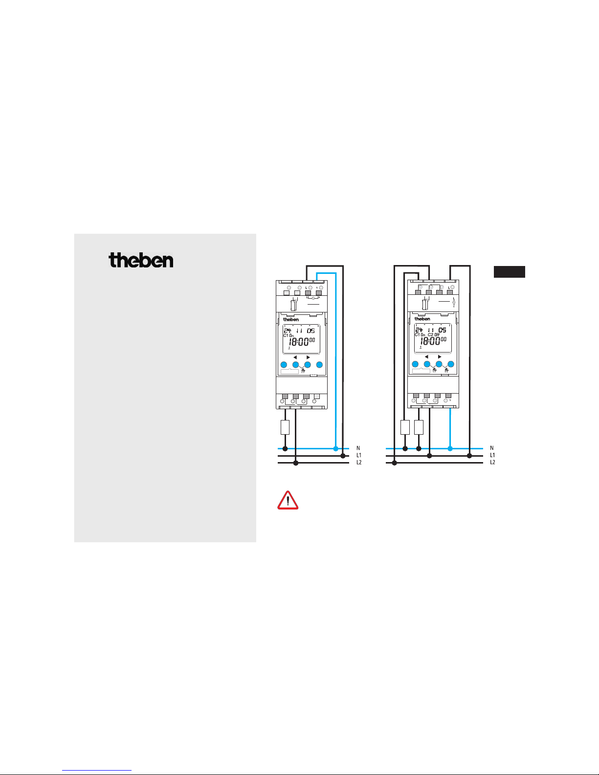
Current connection required for smooth zerocrossing switch operation
(see connection diagram)!
GB
Page 2

Contents
Basic advice 3
Screen display and keys/Operating principle 4
Menu overview 5
Connection/assembly 6
Initial start-up 7
Menu item PROGRAM
Reprogram switching time 8
Change switching time 9
Menu item MANUAL
Manual and permanent switching 10
Menu item OPTIONS
PIN code 10
Memory card OBELISK top2, RESET 11
Technical data 12
Service address/Hotline 12
2
Page 3
3
Basic advice
• The device is designed for installation on DIN top hat rails (in accordance with EN 60715)
• Corresponds to type 1 BSTU in accordance with IEC/EN 60730-2-7
• Power reserve (10 years) is reduced with memory card inserted (in battery mode)
• Designated use:
The timer is used for lighting, air-conditioning, flushing etc. .
• For use only in closed, dry rooms
Do not use on safety devices, e.g. escape route doors, fire safety equipment etc.
• Disposal
Dispose of equipment in an environmentally-friendly manner
GB
Danger of death through electric shock or fire!
Installation should only be carried out by professional electrician!
WARNING
Page 4
4
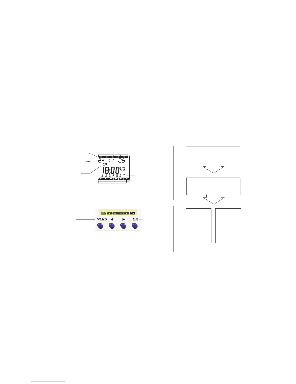
Screen display and keys Operating principle
061218
24
Time display
Date display
Channel status
C1, C2
ON
OFF
MENU
– Activate display
– Open menu
– Terminate programme
– ESC
(Leave menu)
YES
Confirmation
OK
press
NO
Change/
revise
press
OK
– Save
selection
– Confirm
selection
Alternatives
are displayed
Days of the week from
1 – 7
Display of active buttons with
relevant function
Programmed
switch times
1. Read text line
Flashing text/symbol
represents question
2. Make decision
Page 5

5
GB
Menu overview
19 10 06
C1 OFF C2 OFF
9:40
46
PROGRAM
NEW
CHECK
MODIFY
DELETE
END
TIME/DATE MANUAL OPTIONS
END
TIME
SET DATE
SU-WI
WEEK DAY
FORM DATE
FORM TIME
END
PERM ON
PERM OFF
OVERRIDE
ON
HOLIDAY
END
OPERATING
HOUR
LCD ILLUMINA-
TION
LANGUAGE
PIN
FACTORY
SETTINGS
INFO
END
MENU
Page 6

6
Connection/installation
Connect cable
Strip cable by 8 mm (max. 9).
Insert cable at 45° in the open terminal
(2 cables per terminal is possible).
Only for flexible wiring: Press screwdriver downwards
to open spring screwless terminal.
Warning, danger of death through electric shock!
Must be installed by professional electrician!
Disonnect power source.
Cover or shield any adjacent live compo-
nents.
Ensure device cannot be switched on!
Check power supply is disconnected!
Earth and bypass!
WARNING
45° cable
Spring screwless terminal
NC contact
Test tap
Spring screwless
terminal
Page 7

Initial start-up
(see fig.)
Set date, time and summer-/winter
time rule
Press desired button and follow on-screen
instructions.
GB
GERMAN
YEAR
MONTH
DAY
HOUR
MINUTE
SU-WI
EUROPA
SU-WI GB/IRL/P
SU-WI FIN/GR/
TR
SU-WI CDN
SU-WI USA07
SU-W IRAN
SU-WI FREE
RULE
SU-WI FIX DATE
NO SU-WI
ok
ok
19 10 06
C1 OFF C2 OFF
9:40
46
7
Page 8

8
Reprogram swtiching time
(see fig.)
Press MENU.
Confirm with OK or select desired setting .
Reconfirm with OK .
You have 56 memory locations available.
NEW
SWITCH
ok
PROGRAM
same switching time for
several days = Block
Switching
time for
one day
FREE 56
ON On
HOUR
MINUTE
MONDAY
SAVE
COPY
ADD TUESDAY
SAVE
Page 9

9
Change/delete switching time
(see fig.)
Press MENU.
Confirm with OK or select
desired setting .
Reconfirm with OK .
You can either change or delete a block, i.e. a
switching time copied for several days
(e.g. Mon-Fri) or a single switching time.
GB
SWITCH
MONDAY
MODIFY
HOUR
MODIFY
MINUTE
MODIFY
SINGLE DAY
MODIFY BLOCK
ok
PROGRAM
NEW
CHECK
MODIFY
DELETE
Page 10

Manual and permanent
switching
Manual and permanent switching can be selected by using menu option MANUAL or (in the
automatic display) via a combination of buttons
(see fig.).
Activate manual switching
Quickly press both buttons simultaneously.
Activate permanent switching
Press both buttons simultaneously for 2 seconds.
Cancelling manual/permanent switching
Press both buttons simultaneously.
ok
Channel
C1
Channel
C2
PIN code
The PIN code is set in the menu under
OPTIONS (see fig.).
If you have forgotten the PIN call the
Theben Hotline.
OPTIONS
WITH PIN
CURRENT PIN
NEW PIN
00 00
OPERATING
HOUR
LCD ILLUMINA-
TION
LANGUAGE
PIN
FACTO RY
SETTINGS
INFO
ok
10
Page 11

Memory card OBELISK top2
Use memory card
Insert memory card in the timer.
Request saved
switch timings, read to/from
the timer or start Obelisk program.
Memory card OBELISK top2
(No. 907 0 404) after Programming etc. remove
and store in cover
.
Avoid mechanical overload
or contamination caused by other storage/
transport.
RESET
Press the 4 buttons simultaneously.
You can choose between KEEP PROGRAM
and DELETE PROGRAM.
GB
COPY OBELISK ->
TSWI
COPY TSWI ->
OBELISK
RUN OBELISK
CHECK OBELISK
11
Page 12

Technical data
• Nominal voltage: 230–240 V~, +10 %/-15 %
• Frequency: 50-60 Hz
• Power consumption: max. 6 VA
• Switching output: phase-independent
(zero-crossover switching),
• TR 610 top2: suitable for switching SELV
(Safe Extra-Low Voltage)
• Contact: two way switch
• Contact material: AgSnO
2
• Switching capacity max.: 16 A, 250 V~, cos ϕ = 1;
10 A, 250 V~, cos ϕ = 0.6
• Switching capacity min.: 10 mA/230 V AC
100 mA/24 V AC/DC
• Incandescent lamp load: 2600 W
• Halogen lamp load: 2600 W
• Fluorescent lamp load: uncorrected:
1000 VA series corrected
730 VA (80 μF) parallel corrected
• Compact fluorescent lamps: 22 x 7 W, 18 x 11 W
16 x 15 W, 20 x 16 W, 23 x 14 W
• Permissible ambient temperature: –30 °C ... +55 °C
• Protection class: II in accordance with
EN 60730-1 for designated installation
• Protection rating: IP 20 in accordance with
EN 60529
• Pollution level: 2
• Power reserve: 10 years at 20 °C
Service address/Hotline
Service address
Theben AG
Hohenbergstr. 32
72401 Haigerloch
GERMANY
Phone +49 (0) 74 74/6 92-0
Fax: +49 (0) 74 74/6 92-150
Hotline
Phone+49 (0) 74 74/6 92-369
Fax: +49 (0) 74 74/6 92-207
hotline@theben.de
Addresses, telephone numbers etc.
www.theben.de
 Loading...