

Page 1
Presence detector
SPHINX 104-360/2 DIMplus
1. De signa ted u se
2. Es senti al sa fety instr uctio ns
EN
104 0 374
310 519
Designed for surface mounting in standard flush-mounted
socket in the ceiling
For use in residential property, offices, conference rooms
and classrooms
Automatic constant light control for constant lighting
level
2 relays: channel 1 dependent on brightness and presence; channel 2
just dependent on presence
Manual ON/OFF function, with external push button for
activating the detector
Dimming function: automatic dimming
WARNING
Danger of death through electric shock or
fire.
Installation tips
Must be installed by a fully-qualified
electrician.
The device conforms with EN 60669-2-1 subject to designated
installation
3. In stall ation and conne ction
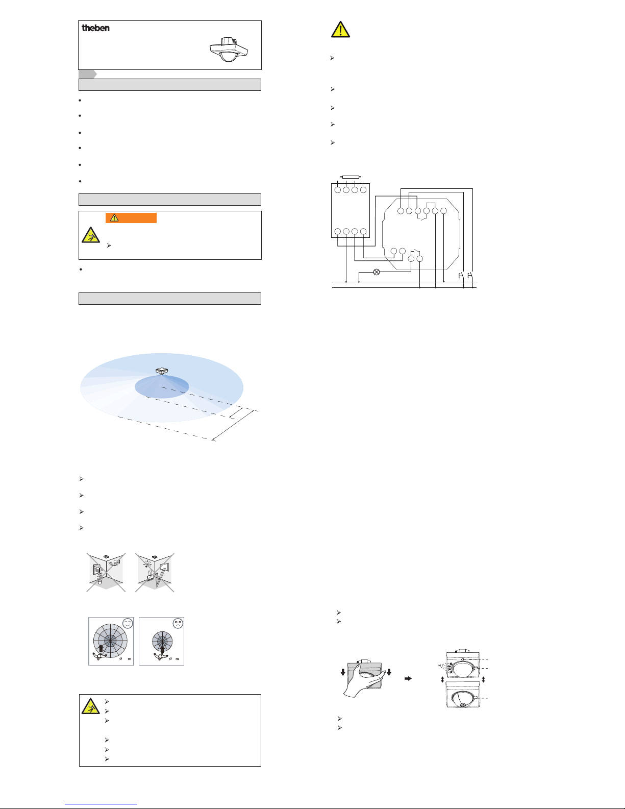
Detection area
Detection area: recommended installation height 2.5 m to 3.5 m
At a height of 2.5 m, the detection area is up to Ø 24 m
and up to Ø 26 m at a height of 3.5 m.
Avoid the following situations:
Connection
reacts more sensitively to
movements across the
detection area
reacts less sensitively to
movements directly at the
presence detector
Do not direct the presence detector at objects with very
reflective surfaces (mirrors, monitors etc.)
Do not install the presence detector near heat sources
(heating outlets, air-conditioning systems, lamps etc.)
Do not direct the presence detector at objects that
move in the wind (curtains, large plants etc.)
Take account of direction of motion when carrying out test. At an
installation height of 3.5 m the detection area across the
presence detector is Ø 26 m and Ø 8 m to the front of the detector.
Must be installed by qualified electrician!
Disconnect power source.
Cover or shield any adjacent live
components.
Ensure device cannot be switched on.
Check power supply is disconnected.
Earth and bypass.
26
8
3 m
12 m
360°
Disconnect the device from the mains when working on the 1–10 V
interface. During installation, treat the interface like a 230 V
power line.
The 1–10 V interface is not disconnected from the mains (no SELV).
Protect device with a series-connected automatic cut-out
type B or C (EN 60898-1) of max. 6 A.
Normal operation
Automatic mode
Semi-automatic mode
Only insert one cable (1.0–2.5 mm2) in each opening of the screwless
terminal strip.
Only use solid copper cables.
1. The channels switch on automatically with movement in automatic
mode. For channel 1, the ambient light level must also be below the
set Lux value. If no motion is detected and the delay time has elapsed,
the channels switch off automatically.
2. Depending on the changing ambient brightness, the presence
detector automatically adjusts the switching On/Off delay time
to avoid the channels switching On and Off unnecessarily.
– Ambient brightness from light to dark: 10 s delay time
– Ambient brightness from dark to light: 5 min delay time:
If the set period of time is <5 min , the channels switch off
in accordance with the set period of time.
3. If the level of ambient light exceeds the set lux value
the lighting switches off automatically within 5 min
(preset switch-on time >5 min). If the switch-on time
< 5 min, the delay time is based on the preset value.
1. In semi-automatic mode, the channels can only be switched on by
pressing an external push button connected to the terminals ext. 1
or ext. 2.
2. If the channels are switched on manually, they switch off
automatically once the last movement has been detected and the
preset time delay has elapsed or switched off by pressing the
external push button.
Installation
SPHINX 104-360/2 DIMplus can be installed in a standard flush-mounted
socket.
Remove housing.
Remove the head of the detector from the power unit by loosening
both screws in the detector head.
Strip back the core insulation by 6–8 mm (see figure).
Press the terminals together to insert the electric cable in the
terminal connections.
Rotary
switches for
time, light
etc.
Drilled hole
transparent
cover
Screw
N
R
D+ D–
B1 B2
R R
OUTPUT
EB
INPUT
–
+
Ext2
Ext1
L‘
N
Connect only one external conductor – do not use dissimilar external
conductors.
L' = channel 1
B1/B2 = channel 2
D+D– = 1–10 V interface
Ext1 = push button input channel 1
Ext2 = push button input channel 2
Page 2
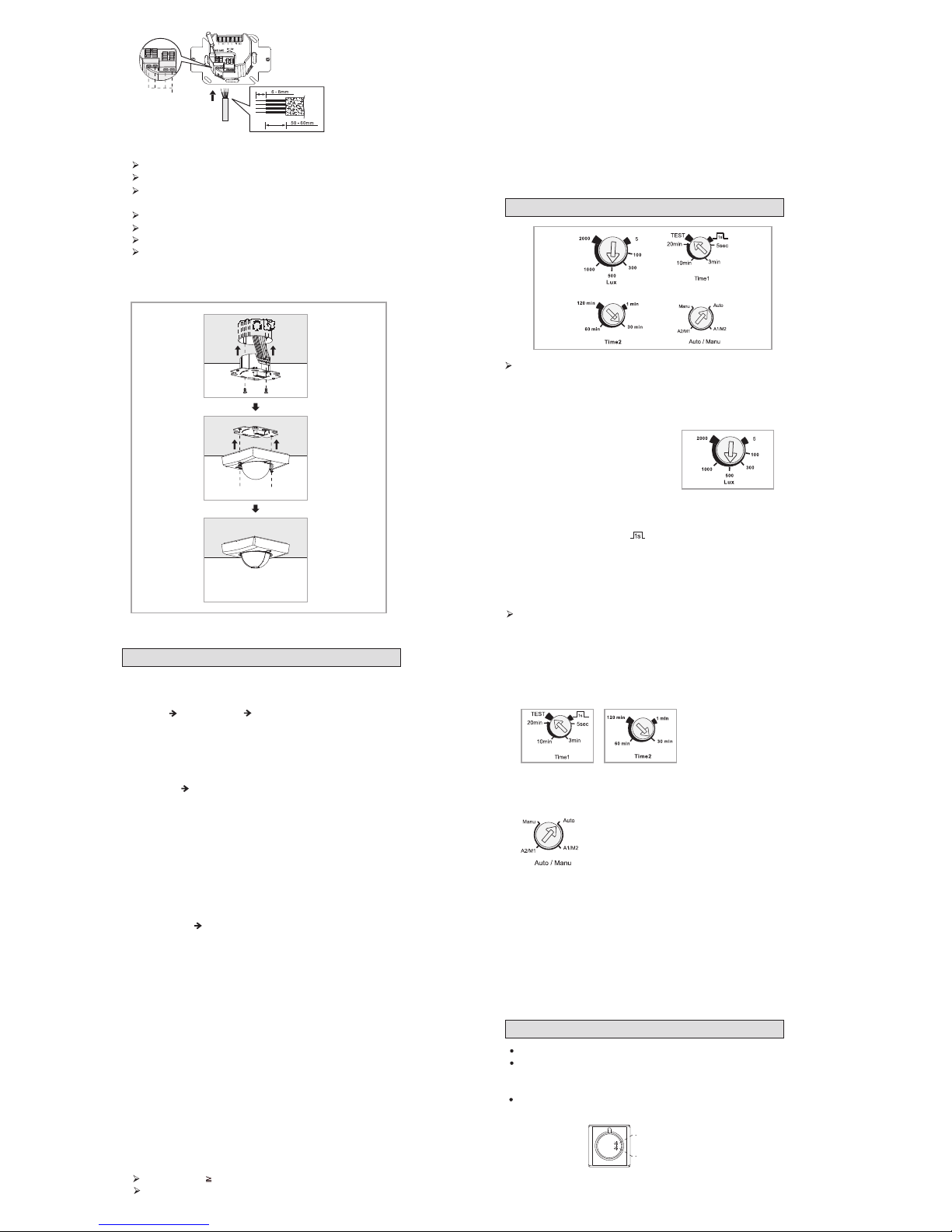
Fasten wires securely.
Place the wired power unit in the standard flush-mounted socket.
Secure the power unit with suitable screws in the flush-mounted
socket.
Plug the detector head onto the power unit.
Switch on the power and check device is working.
Tighten the screws on the detector head.
Attach frame correctly (check based on recess
of transparent cover).
Cable
guide in
terminal
4. Ma nual ON/OF F mod e and dimm ing f uncti on
Manual lighting control
The first press of the button at terminal ext.1 reverses the relay status
(case 1: ON OFF, case 2: OFF ON)
Case 1: Manual switch-off (independent of brightness):
If the lighting is switched on, it can be switched off again
manually. If the lighting is switched off by pressing the button on
terminal ext.1 ( Activation of manual OFF mode), also remains off if
people are present.
If the room is empty for a long period (time delay elapsed), the manual
OFF mode is deactivated; the detector returns to automatic mode.
If the device is in manual OFF mode, a second push of the button
activates the automatic mode.
captive screws
1. Automatic constant light control
Depending on set brightness value, channel 1 (light)
is automatically dimmed up or down to adjust the set brightness
level (the lux value is the same as the light level of the
consumer plus ambient light level).
2. Manual dimming function with external push button
Press button for 2 s: It is dimmed up or down.
Release push button when the desired brightness value has been
achieved.
Manual control or activation of channel 1 (light)
(independent of brightness)
If channel II is in OFF mode, it can be switched on manually.
If channel II is switched on manually by pressing the button
on terminal ext. 2, it stays on until the last movement has
been detected and the preset time delay has elapsed:
It then switches off automatically.
Constant light control
Case 2: Manual switch-on (independent of brightness):
If the lighting is switched off, it can be switched on again
manually. If the lighting is switched on manually by pressing the button
on terminal ext.1 ( Activation of manual ON
mode), it stays on for 30 minutes if people are present.
The device switches to automatic mode after 30 minutes.
1. Automatic constant light control
Depending on set brightness value, channel 1 (light)
is automatically dimmed up or down to adjust the set brightness
level (the lux value is the same as the light level of the
consumer plus ambient light level).
2. Manual dimming function with external push button
Press button for 2 s: It is dimmed up or down.
Release push button when the desired brightness value has been
achieved.
Note: The dimming direction is reversed each time the button is pressed.
5. Se t pot entio meter
6. Di recti on te st an d set -up
Do not set the potentiometer between 2 values in order to
avoid false setting.
SPHINX 104-360/2 DIMplus has 6 lux
settings: 5/100/300/500/1000/2000
lux.
Time settings (TIME)
Light settings (lux)
Test mode for checking detection area
Time1: 4 settings: 5 s/3 min/10 min/20 min, plus TEST (2 s, lux
measurement is irrelevant) and (ON 1 s, OFF 9 s).
Set the time (TIME) rotary switch to test. The detector moves
into test mode and is not influenced by the lux setting. If
the device is started, both the consumers as well as
the LEDs are switched on for 2 seconds and the presence detector
is switched to test standby mode.
Time2: 4 settings: 1 min/30 min/60 min/120 min
Automatic/manual (semi-automatic) mode
Manual: Channel I and channel II are in manual mode
(Semi-automatic mode)
Automatic: Channel I and channel II are in automatic mode
A1/M2: Channel I is in automatic mode and channel II in manual mode
Mode (semi-automatic mode)
A2/M1: Channel I is in manual mode (semi-automatic mode) and
channel II in automatic mode
The SPHINX 104-360/2 DIMplus LED is located behind the lens.
The LED can be used as in indicator for the direction test. If the
detector is started, the LED and consumers switch on for 2 seconds.
The lux setting has no influence.
The LED switches on for 40 seconds in the warm-up phase.
red LED (channel I)
green LED (channel
II)
Page 3
Direction test
The direction test serves to select the most suitable installation site for
the best possible detection area.
Install the presence detector correctly and connect the cable
correctly.
Switch on presence detector.
Switch the time rotary switch (Time) to test and carry out direction
test.
Diagonally to detection area from outside.
When the sensor is triggered, the LED and
consumer switch on for 2 seconds.
If the detector is connected to the mains supply, it needs a warm-up
phase of approximately 40 seconds (consumer and LED are switched on).
The detector then moves into normal mode so that a direction test
can be carried out
.
Restriction of detection area
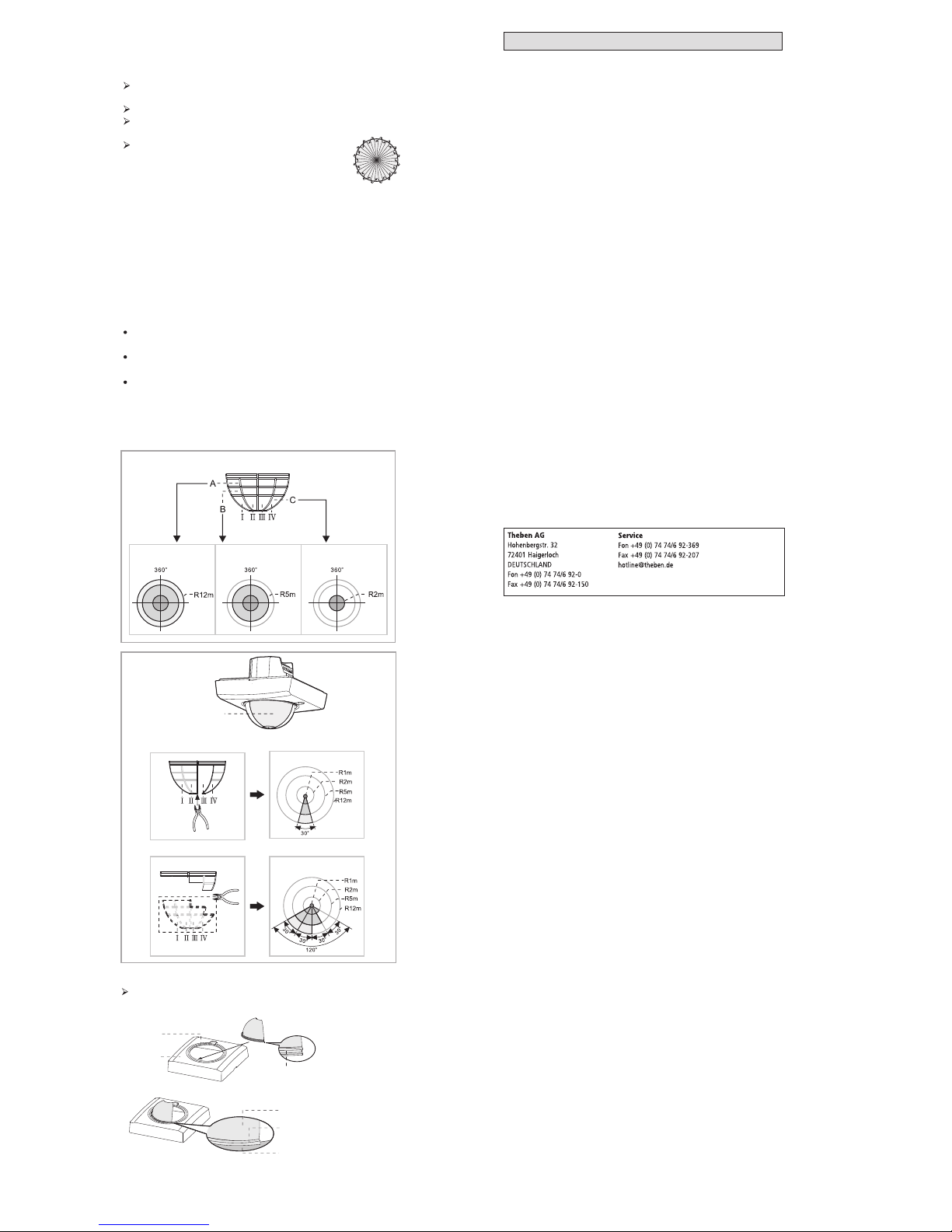
SPHINX 104-360/2 DIMplus has 3 baffles, each with 3
zones (A,B,C). Each layer is divided into 4 small units (I, II, III, IV)
where each unit can cover an angle of approximately 30 °.
The detector is installed at a height of 2.5 m (see figure):
The inner coverage has a Ø of 1 m. The individual
zones of the baffle can be removed using pliers in order to
adjust to the desired detection area.
Remove zones A+B+C: Detection area has a radius of
approximately 12 m circular
Remove zones B+C: Detection area is approximately 10 m,
circular
Remove zone C: Detection area is approximately 4 m, circular
Baffle
Flange of
frame
Screen groove
Baffle
Screen groove
Flange of screen
Housing
Zone ABC removed
the part selected
for removal
Detection area
Detection area
Zone BC removed Zone C removed
ABC BC C
Secure cover: remove cover and attach relevant baffles:
7. Te chnic al da ta
Addresses, telephone numbers etc. at
www.theben.de
Operating voltage: 230 V~ +10 % / -15 %
Frequency: 50–60 Hz
Standby: approx. 1W
Brightness setting range: 5–2000 lx
Detection angle: 360°
Detection area (at a height of 3 m)
walking diagonally / towards/ sitting: ø 24 m / ø 10 m / ø 6 m
Recommended installation height: 2.5–3.5 m
max. total load (channel 1 + 2): 1400 W
CHANNEL 1 LIGHT
Switching output: 230 V (not floating)
Light switch-off delay: 1 s–20 min
Dimming output light: 1–10 V DC, max. 100 mA
Switching capacity LIGHT: 4 A (bei 230 V AC, cos φ = 1)
Incandescent lamp load: 1000 W
Compact fluorescent lamps: 4 x 7 W, 3 x 11 W, 3 x 15 W, 3 x 20 W, 3 x 23 W
Fluorescent lamps (EB): 400 VA
Fluorescent tubes conventional ballast not corrected, series-corrected: 900 VA
Fluorescent tubes conventional ballast not corrected, parallel-corrected:
400 VA (42µF)
CHANNEL 2 PRESENCE
Presence switch-off delay: 1–120 min
Presence switch-on delay: --Switching capacity Presence: 2 A (cos φ= 1 )µ, 30 V DC or 250 V AC
Incandescent lamp load: 400 W
Compact fluorescent lamps: 2 x 7 W, 2 x 11 W, 1 x 15 W, 1 x 20 W, 1 x 23 W
Fluorescent lamps (EB): 40 VA
Fluorescent tubes conventional ballast not corrected, series-corrected: 200 VA
Fluorescent tubes conventional ballast not corrected, parallel-corrected:
60 VA (7µF)
Ambient temperature: –10 °C … +55 °C
Protection class: II
Protection rating: IP 40
 Loading...