

Page 1
The following tools:
—7/16” open-end wrench
(or adjustable wrench)
—Pliers
—Grease gun
Assembly, Use and Care
You have purchased the highest quality professional broadcast spreader available on the market today. The
LCO-1000 is the accumulation of proven performance and will provide you with years of trouble-free service. In
the event you should have any questions or comments, please call our professional support staff.
Thank You!
Our toll-free number is 1-800-225-2639 (U.S. Only)
Before You Begin ...
To assemble your new
spreader, we highly
recommend that you read
all the instructions thoroughly,
familiarize yourself
with the assembly and
components, and verify that all
parts are included in the
package.
You Will Need ...
Model LCO-1000
Professional Rotary Spreader
Page 2
Assembly
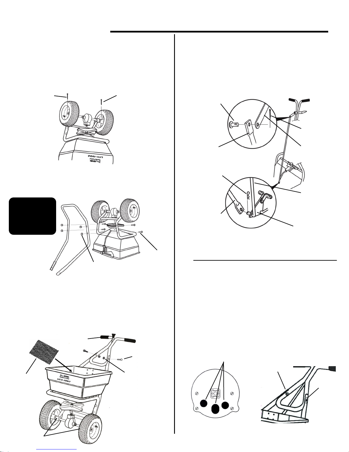
Turn the spreader upside-down. Place the
wheels on the axle with the longer portion of the
hubs facing inward. Secure the drive wheel “A” (right
side) to the axle using the 3/16” cotter pin. Attach the
idler wheel “B” (left side) to axle. Then insert the 1/8”
cotter pin through the axle and secure.
Attach the leg/brace to the frame as shown using
(4) 1/4-20 x 2 1/4” carriage bolts and lock washers,
and nuts.
2)
1)
Turn spreader upright on wheels. Insert screen into
hopper sliding it under the screen clips. Attach the
upper handle assembly to the handle brace with the
handle lever facing as shown. Secure with (2) 1/4-20 x 1
1/2” carriage bolts, lock washers, and nuts. Using a
grease gun, lubricate the grease fittings on the axle.
3)
Install control tube to the handle lever with
(1) 1/4 dia. clevis pin and a 3/32” dia. cotter pin.
Remove the paper tube on the end of the lower control
rod and slip opposite end of control tube over the rod
making sure the pivot lever is between the lower rod
and the control tube. Secure with a hitch pin cotter.
4)
2
1/8” Cotter Pin
B
A
3/16” Cotter Pin
CHECK SPREADER FOR COMPLETE SHUTOFF.
Pull the on/off control lever back to the “OFF”
position. Determine if the holes in the hopper are
completely closed as shown below. Also make sure shut
off plate is not closing too far which will cause the control
lever to bind. If adjustment is needed, loosen the two
carriage bolts holding the upper handle to the leg/brace
assembled in step #3. The holes in the handle are slotted
to allow the upper handle to be moved. Slide the upper
handle toward the hopper to increase the shutoff, move
handle in the opposite direction to reduce shutoff.
Re-tighten bolts and recheck shutoff.
5)
Slotted
Hole
Slotted
Hole
1/4-20 x 1 1/2”
Carriage Bolt
Screen
1/4” Clevis Pin
Control Tube
3/32” Cotter Pin
Handle Lever
Pivot Lever
Hitch Pin Cotter
Lower Control
Rod
Hopper Holes
Completely Closed
Control Tube
Lever Facing Up
Grease Axle
Bearings
Lock washer & Nut
Lock washer & Nut
Place a drop of
oil on bolt
threads to ease
assembly of
locknuts
1/4-20 x 2
1/4” Carriage
Bolt
Page 3
HOW TO USE
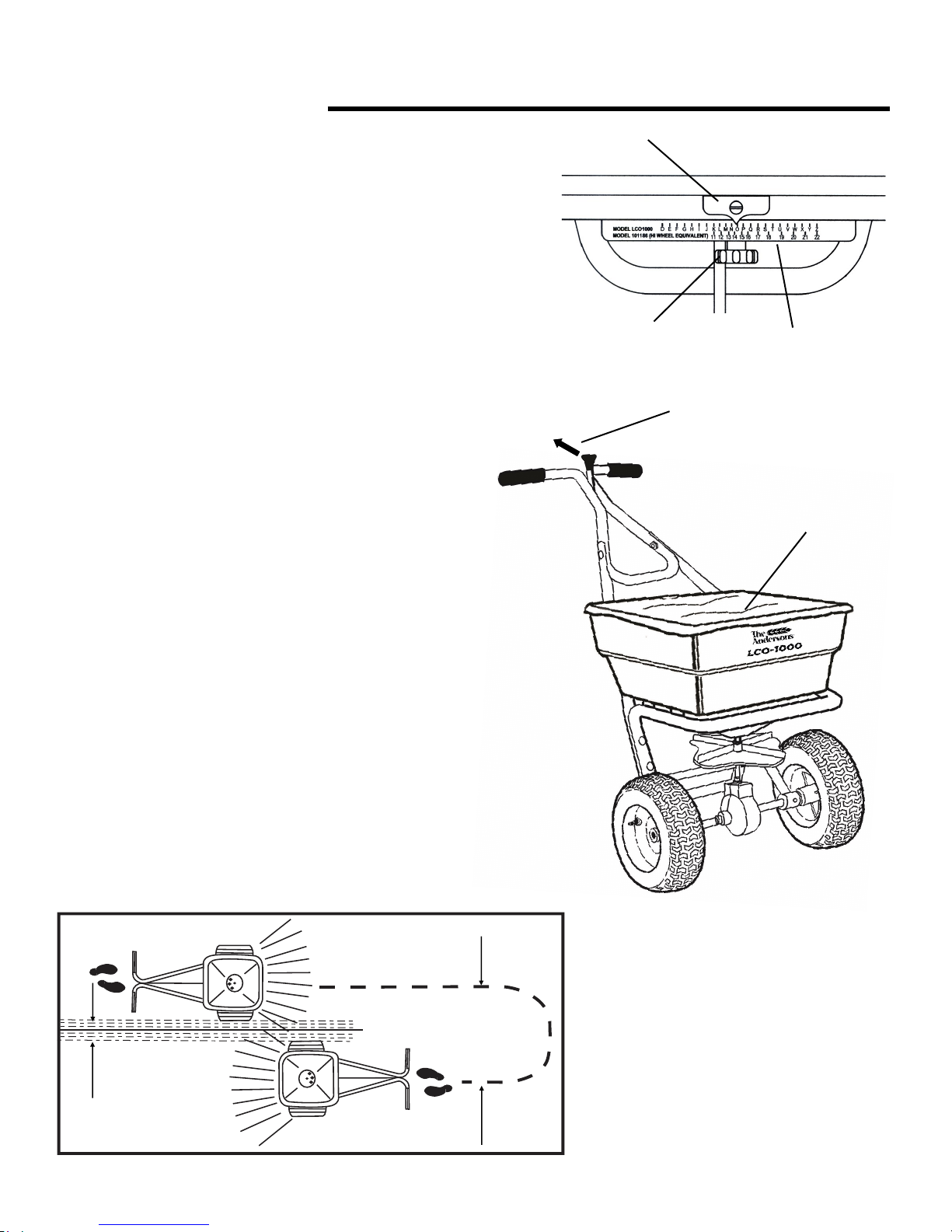
1) Check product bag for rate setting (letter), and swath width.
The rate setting is achieved by loosening the rate control knob
and sliding the rate control plate until the pointer aligns with the
desired letter.
2) Pull the main shutoff lever to the closed position before filling
the hopper.
3) Start rolling the spreader forward before opening the ports:
close ports before stopping.
4) Hold the handle so the hopper is level. Tipping the
spreader to far forward or backward will cause
uneven spreading.
5) Use the swath width recommended on the bag for
your model and push the spreader at 3 MPH (a brisk
walking pace). Apply material in the forward direction
only-not while pulling.
6) The settings given on the product label are
recommended starting points. Test rate and pattern
on a small area before treating a large area.
Actual application rate can vary depending on
weather, spreader conditions, and walking speed.
7) A hopper cover is provided with your new
spreader. Use it to protect the turf product inside the
hopper from light rain or windy conditions during use
and transportation.
3
Use swath width on
package or adjust
per operator’s
walking speed
Overlap
Rate Control
Plate
Pointer
Rate Control
Knob
Operation
Pull Main Shutoff Lever
back to close spreader
Hopper Cover
Page 4
Maintenance
1) Empty the spreader after each use. Return the
unused material to its original container and seal to
prevent moisture-caused clumping.
2) Wash the spreader thoroughly. Let spreader dry in
a sunny or heated area. Wipe or blow off excess
water to prevent corrosion. Clean all residue from the
rotor plate.
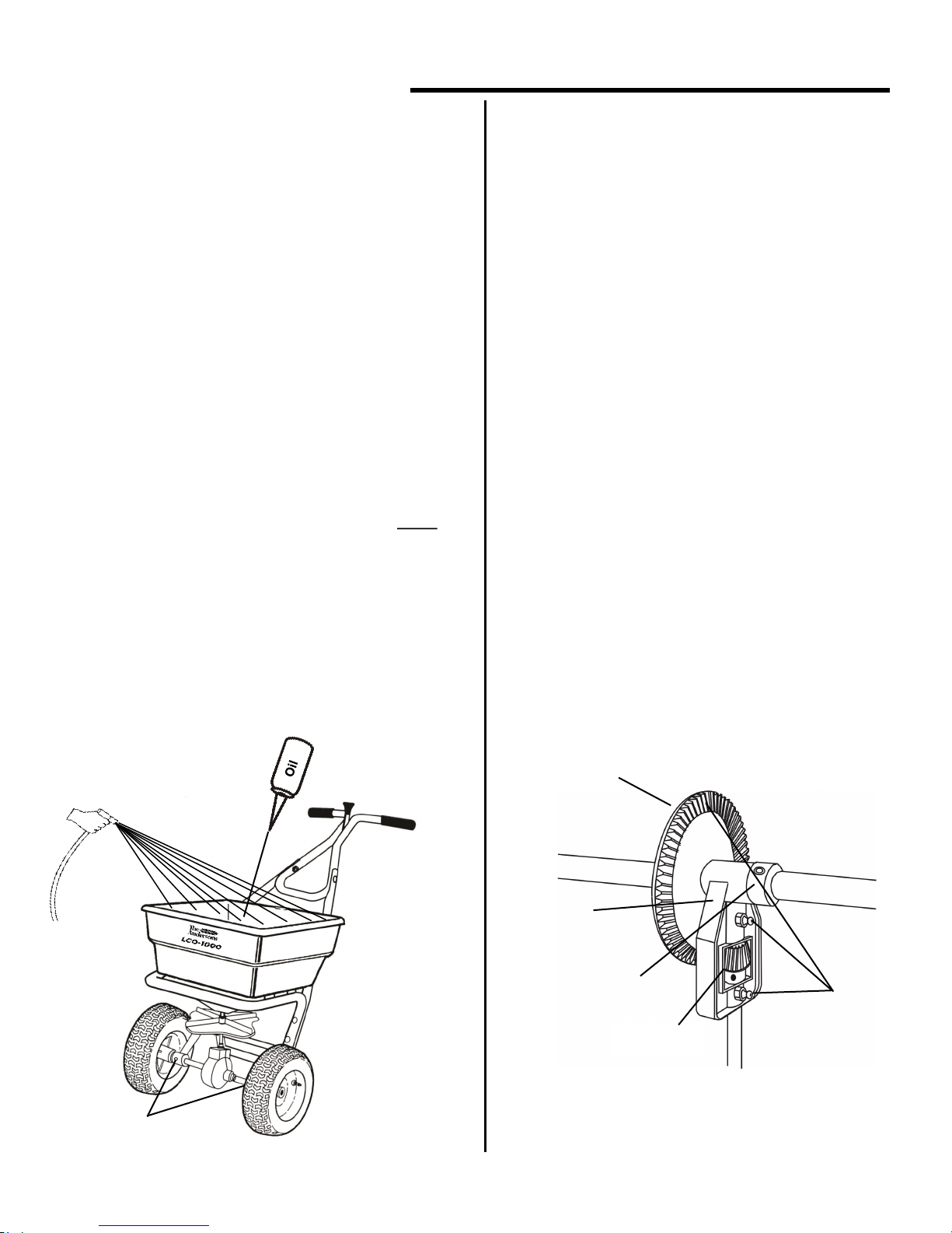
3) Periodically grease the axle bearing housings and
apply a few drops of oil to the impeller shaft bearing
as shown below.
4) Periodically oil the pivot points on all control
linkage and the spring inside the rate control housing.
5) Periodically clean and inspect the gears by
removing the gearbox cover halves. Apply a small
amount of grease to fittings on the gear carrier and
the gear teeth for lubrication. Be sure to reinstall the
gearbox cover halves prior to use.
4
6) Gear mesh should be checked on a regular
basis during high use periods. Clearance between
the axle gear and pinion gear should be minimal
but not tight. If adjustment is necessary, loosen
axle collar set screw and hold gears together. Slide
axle collar against the gear support and tighten
axle collar set screw. Spin drive wheel. Gears
should run freely and smoothly.
7) Maintain tire pressure at 20 psi maximum.
8) If the axle requires disassembly, be sure to
reassemble it so the drive wheel attaches on the
right side as you push the spreader. Incorrect
spread pattern will result if the rotor plate does not
rotate in a counter-clockwise direction.
Axle Collar
Grease
Pinion Gear
Axle Gear
Oil Impeller Shaft
Bearing in Hopper
Grease Axle
Bearings
Gear Support
Page 5
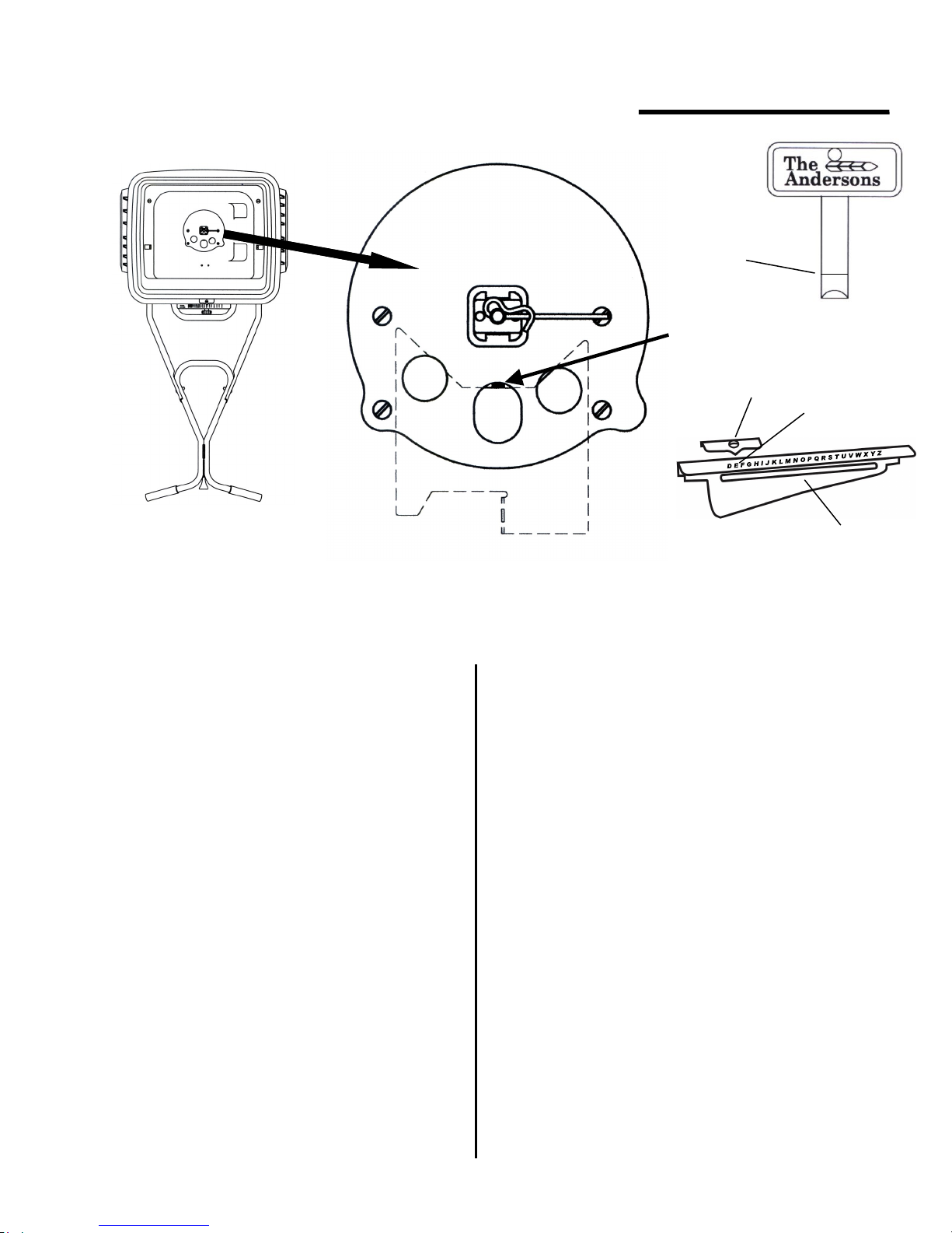
Calibration Instructions
1) Pull the main shutoff lever to the closed posi-
tion.
2) Set the rate control plate to the “E” setting.
3) Push the main shutoff lever to the open position.
4) Insert the Calibration Key vertically into the
center port hole, as shown above.
5) If the calibration key fits snugly, the spreader is
properly calibrated. If not, continue with steps 6-13.
6) Loosen the rate control knob and slide the rate
plate all the way to the left.
7) Insert the calibration key as described in Step
#4.
8) Pull the main shutoff lever to ease the shutoff
plate against the calibration key. Use the main
shutoff lever to hold the calibration key in place.
Your professional spreader has been factory calibrated. For best results,
occasionally check calibration and adjust if necessary.
9) Slide the rate control plate to the right until it
comes in contact with the protruding end of the
rate control rod.
10) Tighten the rate control knob.
11) Remove the calibration key and pull the
main shutoff lever to the closed position.
12) Loosen the nuts securing the rate control
pointer and slide the pointer so that it centers on
the “E” setting of the rate control plate
13) Re-tighten the screw on the pointer.
5
Calibration
depth
Calibration Key
Pointer
Rate Control
Plate
Setting “E”
Page 6
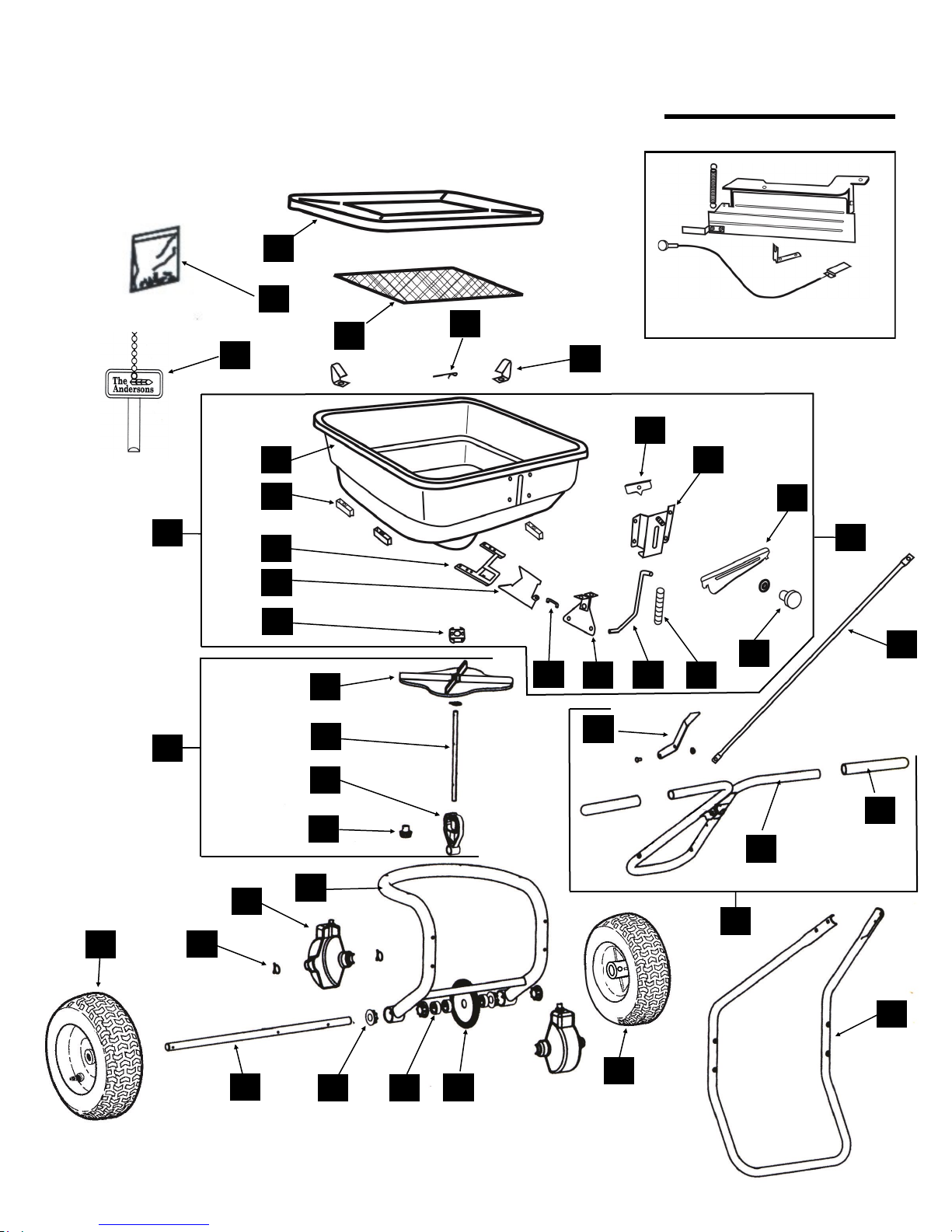
Parts Diagram–LCO-1000
32
39
37
35
2 33
32
31
30
29
28
27
26
1
3
4
5
6
7
8
9
10
11
25
12
13
14
15
16
17
18
19
21
38
22
23
24
36
20
34
6
1
#16579 Optional Deflector Kit
(Used for side spread pattern shutoff)
40
Page 7
KEY # PART DESCRIPTION PART #
1 Hopper Assembly 16591
2 Hopper * 16592
3 Hopper Spacer (set of 4) 16603
4 Shutoff Plate Guide * 14836-1
5 Shutoff Plate * 16594
6 Impeller Shaft Bearing Assembly * 14312-1
7 Impeller Assembly (includes #8 thru #11) 16596
8 Impeller 16597
9 Impeller Shaft 16598
10 Gear Carrier, Complete w/ Grease Fittings 780155
11 Pinion Gear 780122
12 Idler Wheel 14857
13 Retainer Clip (set of 3) 780180
14 Gearbox Cover Half (set of 2) 780110
15 Frame Assembly (includes #17) 16600
16 Axle 16599
17 Axle Bearing (set of 4) 16412
18 Axle Collar (set of 3) 780200
19 Ring Gear 780121
20 Drive Wheel 14856
21 Rest 16604
22 Upper Handle Assembly (includes #23 & #25) 15512
23 Hand Grips (set of 2) 14870
24 Upper Handle 15498
25 Main Shutoff Lever Assembly 15513
26 Shutoff Plate Link * 14846
27 Pivot Lever Assembly * 14878
28 Lower Control Rod w/ swivel * 14917
29 Rate Control Spring * 13354
30 Rate Control Knob/Washer * 12704
31 Control Tube 14916
32 Rate Control Plate * 16595
33 Rate Control Housing * 15527
34 Pointer * 12708
35 Hopper Screen Clip (set of 2) 780440
36 Agitator Pin 780100
37 Hopper Screen 14863
38 Fastener Pack 15579-1
39 Hopper cover 14606-1
40 Calibration Key (see calibration instructions) 15740
—
Optional Side Deflector Kit (Product Code SDSHIELDLCO)
16579
Ordering Parts
1) Part number (DO NOT use key numbers when ordering parts. ALWAYS use part numbers.)
2) Part description
3) The Andersons model LCO1000 (product code ASPLCO1000)
See diagram for assistance in identifying specific parts.
For parts orders, call 1-800-294-0671. (Note: Sales of parts for the Andersons spreaders are handled by EarthWay.
IMPORTANT: When ordering replacement parts, always provide the following information:
For More
Information
Call . . .
1-800-225-2639
(U.S. Only)
The Andersons’ toll-free
Helpline. This helpline is
provided to give you more
Information about
Andersons Turf Products.
………………………………..
Or Visit Our
Website At …
www. andersonsturf.com
The Andersons, Inc.
480 Dussel Drive
Maumee, OH 43537 USA
* Indicates parts in Hopper Assembly
7
Page 8

Warranty
It is our first priority to improve our products’ quality
and performance whenever possible.
Your comments and questions are always welcome-
Please call our Helpline: 1-800-225-2639
(U.S. Only)
Or Visit Our Website At …
www.andersonspro.com
The Andersons, Inc.
480 Dussel Drive
Maumee, OH 43537
LCO1000 MANUAL0115
The Andersons warrants to Purchaser the following:
1. Product will be free of defects in materials and workmanship for a period of one year from date of purchase.
2. The axle gear, gear support, pinion gear, axle, and axle bearings have a limited lifetime warranty to be free of defects in materials and workmanship.
3. If the spreader is used for commercial rental the Limited Warranty shall be limited to a period of 90 days.
4. All Unit and part replacement will be performed at the reasonable discretion of The Andersons and EarthWay.
5. Labor charges are not covered and the unit need not be returned to the dealer for warranty service.
6. Proof of purchase must be supplied to The Andersons.
7. For warranty questions, contact EarthWay at 1-800-294-0671.
The Andersons sole obligation under this warranty is limited to repairing or replacing the defective part.
This warranty does not extend to any Product or parts thereof that have been allowed to corrode, subjected to misuse, neglect, accident, or modification
by anyone other than The Andersons or that have been affixed to any nonstandard accessory attachment or that have been used, stored, installed,
maintained operated in violation of The Andersons instructions or standard industry practice. No agent, employee or representative of The Andersons
has any authority to bind The Andersons to any affirmation, representation or warranty concerning the Product and any affirmation, representation or
warranty made by any agent, employee or representative shall not be enforceable by Purchaser.
THIS WARRANTY EXTENDS ONLY TO THE ORIGINAL PURCHASER AND IS EXPRESSLY IN LIEU OF ANY OTHER EXPRESS OR IMPLIED
WARRANTIES, INCLUDING WITHOUT LIMITATION ANY IMPLIED WARRANTY OR MERCHANTABILITY OR FITNESS OR INTENDED USE FOR
A PARTICULAR PURPOSE AND OF ANY OTHER OBLIGATION ON THE PART OF The Andersons. The Andersons SHALL NOT BE LIABLE
FOR ANY INCIDENTAL, SPECIAL OR CONSEQUENTIAL LOSS, DAMAGE OR EXPENSE DIRECTLY OR INDIRECTLY ARISING FROM THE USE
OF ANY OF THE PRODUCT INCLUDING, BUT NOT LIMITED TO, DAMAGE OR LOSS OF OTHER PROPERTY OR EQUIPMENT, LOSS OF
PROFITS OR REVENUE, COST OF CAPITAL, COST OF PURCHASED OR REPLACEMENT GOODS, OR CLAIMS OF CUSTOMERS OF
PURCHASER.
 Loading...