


Pilot Operating Handbook
The Airplane Factory SLING
THE AIRPLANE FACTORY (Pty) Ltd.
HANGAR 8 TEDDERFIELD AIR PARK, JHB SOUTH, EIKENHOF, 1872, SOUTH AFRICA
PO BOX 308, EIKENHOF, 1872, SOUTH AFRICA
Phone: +27 11 948 9898
Information: info@airplanefactory.co.za
The Airplane Factory, Inc
3401 Airport Drive, Torrance, CA, 90505
Phone: 424-241-0341
info@airplanefactory.com
Date of Issue: 07 July 2014 Revision Number: 1. 3

This airplane must be operated in
compliance with information and
limitations contained herein. This
pilot operating handbook must be
available on board of the airplane at
all times.
Airplane model : Airplane Factory Sling LSA
Manufacturer : The Airplane Factory (Pty) Ltd
Airplane Serial Number : ……………………………….
Date of Construction : ………………………………..
Registration : ……………………………………….
Airworthiness Category : Light Sport Aircraft (LSA)
Issue Date of POH : 07 July 2014
PLEASE ADVISE THE AIRPLANE FACTORY ON CHANGE
OF OWNERSHIP OF THE AIRCRAFT
Date of Issue: 07 July 2014 Revision : 1.3
Page | ii

NOTICE
WITH RESPECT TO ELECTRICAL WIRING, AIRCRAFT MANUFACTURED BEFORE
AUGUST 2014 MAY NOT BE FULLY COMPLIANT WITH THIS MANUAL.
THIS MANUAL IS WRITTEN FOR THE STANDARD 912 ULS POWERED SLING LSA,
AS MANUFACTURED ON PREMISES BY THE AIRPLANE FACTORY (PTY) LTD).
DIFFERENCES APPLICABLE TO THE STANDARD 912 iS POWERED SLING LSA
AIRCRAFT, AS MANUFACTURED ON PREMISES BY THE AIRPLANE FACTORY
(PTY) LTD, ARE INCLUDED IN A SUPPLEMENT IN SECTION 9 OF THIS
HANDBOOK.
AIRCRAFT WHICH DIFFER FROM THE PRODUCTION STANDARD, IN WHATEVER
WAY, ARE NOT ADDRESSED IN THIS MANUAL, EXCEPT TO THE EXTENT SAID
AIRCRAFT CORRESPOND WITH THE PRODUCTION STANDARD.
NOTICE
THIS EDITION OF THIS MANUAL IS APPLICABLE TO AIRCRAFT REGISTERED IN
THE USA. DEFINITIONS ARE ACCORDINGLY CONSISTENT WITH US
REGULATIONS ONLY.
Date of Issue: 07 July 2014 Revision : 1.3
Page | iii

POH Compliance Notice
ASTM Standards used for the design, construction, and continued
airworthiness:
ASTM F2279.
ASTM F2295.
ASTM F2245.
Quality assurance records are stored both with the original
manufacturer in South Africa and with its US distributor at the
addresses below.
The Airplane Factory (Pty) Ltd
Hangar 8 Tedderfield Air Park, Johannesburg South, Eikenhof, 1872,
South Africa
PO Box 308, Eikenhof, 1872, South Africa
Phone: +27 11 948 9898
info@airplanefactory.co.za
The Airplane Factory USA
3401 Airport Drive, Torrance, CA, 90505
Phone: 424-241-0341
info@airplanefactory.com
Page | iv
Date of Issue: 07 July 2014 Revision : 1.3

Airplane Factory SLING LSA
Pilot Operating Handbook
Continued Operational Safety Monitoring
Manufacturer Responsibilities
The Airplane Factory has a procedure in place to monitor the safety of
the fleet and to alert pilots of any potential safety issues. The owner of a
Light Sport Aircraft is responsible for making sure they receive pertinent
safety information and complying with bulletins. The owner of a Light
Sport Aircraft is also responsible for alerting the manufacturer of any
potential safety of flight issues.
Report a Safety of Flight Issue
Please contact our US Distribution Center to report any maintenance,
service or safety issues.
Service/Maintenance/Safety issues: safety@airplanefactory.com
or
fill out a safety/service form on our website: www.airplanefactory.com.
Sign up to receive safety notices
Method for Owner/Operator to obtain the latest Safety of Flight
Information:
Please sign up on our website for continued safety/service updates:
www.airplanefactory.com, or call 424-241-0341, and we’ll sign you up. In
addition, all updates will be posted to our website.
Page | v
Date of Issue: 07 July 2014 Revision : 1.3

Airplane Factory SLING LSA
Pilot Operating Handbook
Detailed Owner/Operator Responsibilities
Each owner/operator of a LSA shall read and comply with the
maintenance and continued airworthiness information and instructions
provided by the manufacturer.
Each owner/operator of a LSA shall be responsible for providing the
manufacturer with current contact information, where the
manufacturer may send the owner/operator supplemental notification
bulletins.
The owner/operator or a LSA shall be responsible for notifying the
manufacturer of any safety of flight issue or significant service difficulty,
upon discovery.
The owner/operator of a LSA shall be responsible for complying with all
manufacturer issued notices of corrective action and for complying with
all applicable aviation authority regulations in regard to maintaining the
airworthiness of the LSA.
An owner of a LSA shall ensure that any needed corrective action be
completed as specified in a notice, or by the next scheduled annual
inspection.
Should an owner/operator not comply with any mandatory service
requirements, the LSA shall be considered not in compliance with
applicable ASTM standards and may be subject to regulatory action by
the presiding aviation authority (FAA).
Page | vi
Date of Issue: 07 July 2014 Revision : 1.3

Airplane Factory SLING LSA
Rev
No.
Affected
Section
Affected
Pages
Date of
Issue
Approve
d by
Date of
approval
Date
inserted
Sign.
1.1
All
All
04/20/2011
1.2
All
All
03/12/2012
1.3
All
All
07/07/2014
Pilot Operating Handbook
RECORD OF REVISIONS
Any revisions to this Pilots Operating Handbook must be recorded in the
following table, and, where applicable, be endorsed by the responsible
airworthiness authority
Revision numbers and dates appear at the foot of each page.
Date of Issue: 07 July 2014 Revision : 1.3
Page | vii
Airplane Factory SLING LSA
Page
Page
Status
Latest
Revision
Page
Page
Status
Latest
revision
i
Revised
1.3
1-10
Revised
1.3
ii
Revised
1.3
1-11
Revised
1.3
iii
Revised
1.3
1-12
Revised
1.3
iv
Revised
1.3
1-13
Revised
1.3
v
Revised
1.3
1-14
Revised
1.3
vi
Revised
1.3
1-15
Revised
1.3
vii
Revised
1.3
1-16
Revised
1.3
viii
Revised
1.3
1-17
Revised
1.3
ix
Revised
1.3
1-18
Revised
1.3
x
Revised
1.3
2-1/2-
2
Revised
1.3
xi
Revised
1.3
2-3
Revised
1.3
xii
Revised
1.3
2-4
Revised
1.3
1-1/1-
2
Revised
1.3
2-5
Revised
1.3
1-3
Revised
1.3
2-6
Revised
1.3
1-4
Revised
1.3
2-7
Revised
1.3
1-5
Revised
1.3
2-8
Revised
1.3
1-6
Revised
1.3
2-9
Revised
1.3
Pilot Operating Handbook
LIST OF EFFECTIVE PAGES
Date of Issue: 07 July 2014 Revision : 1.3
Page | viii

Airplane Factory SLING LSA
1-7
Revised
1.3
2-10
Revised
1.3
1-8
Revised
1.3
2-11
Revised
1.3
1-9
Revised
1.3
2-12
Revised
1.3
2-13
Revised
1.3
3-14
Revised
1.3
2-14
Revised
1.3
3-15
Revised
1.3
2-15
Revised
1.3
3-16
Revised
1.3
2-16
Revised
1.3
3-17
Revised
1.3
2-17
Revised
1.3
3-18
Revised
1.3
2-18
Revised
1.3
3-19
Revised
1.3
2-19
Revised
1.3
4-1/4-
2
Revised
1.3
2-20
Revised
1.3
4-3
Revised
1.3
2-21
Revised
1.3
4-4
Revised
1.3
2-22
Revised
1.3
4-5
Revised
1.3
3-1/3-
2
Revised
1.3
4-6
Revised
1.3
3-3
Revised
1.3
4-7
Revised
1.3
3-4
Revised
1.3
4-8
Revised
1.3
3-5
Revised
1.3
4-9
Revised
1.3
3-6
Revised
1.3
4-10
Revised
1.3
3-7
Revised
1.3
4-11
Revised
1.3
3-8
Revised
1.3
4-12
Revised
1.3
Pilot Operating Handbook
Date of Issue: 07 July 2014 Revision : 1.3
Page | ix

Airplane Factory SLING LSA
3-9
Revised
1.3
4-13
Revised
1.3
3-10
Revised
1.3
4-14
Revised
1.3
3-11
Revised
1.3
4-15
Revised
1.3
3-12
Revised
1.3
4-16
Revised
1.3
3-13
Revised
1.3
4-17
Revised
1.3
Pilot Operating Handbook
Date of Issue: 07 July 2014 Revision : 1.3
Page | x

Airplane Factory SLING LSA
Page
Page Status
Latest Revision
Page
Page Status
Latest Revision
4-18
Revised
1.3
7-6
Revised
1.3
4-19
Revised
1.3
7-7
Revised
1.3
4-20
Revised
1.3
7-8
Revised
1.3
5-1/5-2
Revised
1.3
7-9
Revised
1.3
5-3
Revised
1.3
7-10
Revised
1.3
5-4
Revised
1.3
7-11
Revised
1.3
5-5
Revised
1.3
7-12
Revised
1.3
5-6
Revised
1.3
7-13
Revised
1.3
5-7
Revised
1.3
7-14
Revised
1.3
6-1/6-2
Revised
1.3
7-15
Revised
1.3
6-3
Revised
1.3
7-16
Revised
1.3
6-4
Revised
1.3
7-17
Revised
1.3
6-5
Revised
1.3
7-18
Revised
1.3
6-6
Revised
1.3
7-19
Revised
1.3
6-7
Revised
1.3
7-20
Revised
1.3
6-8
Revised
1.3
7-21
Revised
1.3
6-9
Revised
1.3
7-22
Revised
1.3
7-1/7-2
Revised
1.3
7-23
Revised
1.3
7-3
Revised
1.3
7-24
Revised
1.3
7-4
Revised
1.3
7-25
Revised
1.3
7-5
Revised
1.3
7-26
Revised
1.3
Pilot Operating Handbook
Date of Issue: 07 July 2014 Revision : 1.3
Page | xi

Airplane Factory SLING LSA
Page
Page Status
Latest
Revision
Page
Page
Status
Latest
Revision
7-27
Revised
1.3
9-7
Revised
1.3
7-28
Revised
1.3
9-8
Revised
1.3
7-29
Revised
1.3
9-9
Revised
1.3
7-30
Revised
1.3
9-10
Revised
1.3
7-31
Revised
1.3
9-11
Revised
1.3
7-32
Revised
1.3
9-12
Revised
1.3
8-1/8-2
Revised
1.3
9-13
Revised
1.3
8-3
Revised
1.3
9-14
Revised
1.3
8-4
Revised
1.3
9-15
Revised
1.3
8-5
Revised
1.3
9-16
Revised
1.3
8-6
Revised
1.3
9-17
Revised
1.3
8-7
Revised
1.3
9-18
Revised
1.3
8-8
Revised
1.3
9-19
Revised
1.3
8-9
Revised
1.3
9-20
Revised
1.3
9-1/9-2
Revised
1.3
9-21
Revised
1.3
9-3
Revised
1.3
9-4
Revised
1.3
9-5
Revised
1.3
9-6
Revised
1.3
Pilot Operating Handbook
Date of Issue: 07 July 2014 Revision : 1.3
Page | xii

Airplane Factory SLING LSA
Pilot Operating Handbook
TABLE OF CONTENTS
1. GENERAL INFORMATION .......................................................................... 1-1
2. LIMITATIONS ............................................................................................. 2-1
3. EMERGENCY PROCEDURES ....................................................................... 3-1
4. NORMAL PROCEDURES ............................................................................. 4-1
5. PERFORMANCE ......................................................................................... 5-1
6. WEIGHT AND BALANCE ............................................................................. 6-1
7. SYSTEMS ................................................................................................... 7-1
8. AIRPLANE GROUND HANDLING AND SERVICING ...................................... 8-1
9. SUPPLEMENTARY INFORMATION ............................................................. 9-1
Page | xiii
Date of Issue: 07 July 2014 Revision : 1.3

Airplane Factory SLING LSA
Pilot Operating Handbook
1. GENERAL INFORMATION
1.1 Introduction to airplane............................................................................ 1-3
1.2 Warnings, cautions and notes .................................................................. 1-4
1.3 Aircraft 3-view drawing ............................................................................ 1-5
1.4 Data for Sling LSA aircraft and systems ..................................................... 1-7
1.5 Terminology, symbols and conversion factors ........................................ 1-12
1.6 Supporting documents ........................................................................... 1-18
Page | 1-1/1-2
Date of Issue: 07 July 2014 Revision : 1.3

Airplane Factory SLING LSA
Pilot Operating Handbook
1.1 Introduction to airplane
The Airplane Factory Sling LSA is a two seat (side-by-side), single engine,
tricycle undercarriage aluminum aircraft with a conventional low wing design
and is compliant with the requirements of the FAA Light Sport Aircraft (LSA)
category according to ASTM Standards F2245, F2279 and F2295.
With only minor modifications to the aircraft and the application of a revised
Pilot’s Operating Handbook the Sling LSA may be made to comply with the
requirements of the EASA (European Aviation Safety Agency) CS-VLA
(Certification Standard Very Light Aircraft) standard, having a maximum all up
weight of 700 kg (1543.24 lb).
The Sling LSA is intended chiefly for recreational and cross-country flying. It is
not intended for aerobatic operation. It is considered to be suitable for use as
a trainer. This Pilot Operating Handbook has been prepared to provide pilots
with information for the safe and efficient operation of the Sling LSA.
Page | 1-3
Date of Issue: 07 July 2014 Revision : 1.3

Airplane Factory SLING LSA
WARNING
CAUTION
NOTE
Pilot Operating Handbook
1.2 Warnings, cautions and notes
The following definitions apply to warnings, cautions and notes in the Pilot
Operating Handbook.
Means that non-observation of the corresponding procedure leads to an
immediate or important degradation of flight safety.
Means that non-observation of the corresponding procedure leads to a
minor or possible long term degradation of flight safety.
Draws attention to any special item not directly related to safety but which
is important or unusual.
Page | 1-4
Date of Issue: 07 July 2014 Revision : 1.3

Airplane Factory SLING LSA
DIMENSIONS IN THIS DRAWING
ARE IN FEET.
Pilot Operating Handbook
1.3 Aircraft 3-view drawing
Page | 1-5
Date of Issue: 07 July 2014 Revision : 1.3

Airplane Factory SLING LSA
DIMENSIONS IN THIS DRAWING
ARE IN FEET.
Pilot Operating Handbook
Page | 1-6
Date of Issue: 07 July 2014 Revision : 1.3

Airplane Factory SLING LSA
Pilot Operating Handbook
1.4 Data for Sling LSA aircraft and systems
WING
Wing span: 9.165 m (30 ft).
Mean Aerodynamic Chord: 1.339 m (52.7 inch).
Wing surface area: 11.845 m2 (131.75 ft2).
Wing loading: 59.10 kgm
Aspect ratio: 7.04.
Taper ratio: 1.375.
Dihedral: 5o
FUSELAGE
-2
(11.7 lb /ft2).
Fuselage length: 5.77 m (19 ft).
Overall length: 6.675 m (21ft 11 inches).
Overall width: 1.15 m (45 inches).
Overall height: 2. 5m (98 inches).
EMPENNAGE
Horizontal stabilizer span: 2.825 m (9 ft 3 inch).
Horizontal stabilizer surface area: 0.96 m2 (10 ft2).
Elevator surface area: 1.02 m
2
(11 ft2).
Horizontal stabilizer angle of incidence -4o
Vertical stabilizer span: 1.47 m (16 ft).
Vertical stabilizer surface area: 0.53 m2 (6 ft2).
Rudder surface area: 0.59 m2 (6 ft2).
LANDING GEAR
Wheel track: 1.95 m (6ft 5 inches).
Wheel base: 1.41m (4ft 6 inches).
Brakes: Hydraulic.
Main gear tires: 15x6.00-6, 6-ply (2.2 bar /
30 psi) pressure).
Page | 1-7
Date of Issue: 07 July 2014 Revision : 1.3

Airplane Factory SLING LSA
Pilot Operating Handbook
Nose gear tires: 5.00-5, 6-ply (1.8 bar / 26 psi
CONTROL SURFACE TRAVEL LIMITS
Ailerons: 24o up and down (±2°).
Elevator: 30o up and 20o down (±2°).
Trim tab: 5o up and 32o down (±5°).
Rudder: 25o left and right (±2°).
Flaps: 0o to 30o down(±3°).
ENGINE
pressure).
Manufacturer: Bombardier-Rotax GmbH.
Model: 912 ULS.
Type: 4 Cylinder horizontally opposed with overall
displacement 1 352 cc, mixed cooling (water-cooled
heads and air-cooled cylinders), twin carburetors,
integrated reduction gearbox with torque damper
Maximum power: 73.5 kW (98.5hp) at 5 800 rpm (maximum 5 minutes).
69 kW (92.5hp) at 5 500 rpm (continuous).
For Sling LSA aircraft fitted with the 912 iS engine refer to the applicable
supplement at the end of this manual.
PROPELLER
Manufacturer: Warp drive.
No of blades: 3.
Diameter: 1.83 m (72 inches).
Type: Composite.
Page | 1-8
Date of Issue: 07 July 2014 Revision : 1.3

Airplane Factory SLING LSA
Pilot Operating Handbook
FUEL
Fuel grade: Minimum RON 95 / minimum AKI 91.
MOGAS: EN 228 Super, EN 228 Super plus,
ASTMD4814.
Leaded AVGAS: AVGAS 100LL (ASTM D910).
Unleaded AVGAS: UL91 (ASTM D7547).
(Refer to latest revision of engine operator /
maintenance manual and latest revision of
service instruction SI-912-016. For aircraft fitted
with the 912 iS engines refer to the applicable
supplement at the end of this manual).
Fuel tanks: Two. One fuel tank integrated within each wing
Capacity of tank: 75 liters (19.8 US gallons), 73 liters (19.3 US
Total capacity: 150 liters (39.6 US gallons).
Total usable fuel: 146 liters (38.6 US gallons).
leading edge. Each tank is equipped with finger
strainers (in pick up line) and drain fittings.
gallons useable).
Page | 1-9
Date of Issue: 07 July 2014 Revision : 1.3

Airplane Factory SLING LSA
Pilot Operating Handbook
OIL SYSTEM
Oil system type: Forced, with external oil reservoir.
Oil: Automotive grade API “SF” or “SG” type oil
preferably synthetic or semi-synthetic. When
operating on unleaded fuels or MOGAS fully
synthetic oil is recommended.
(Refer to latest revision of engine operator /
maintenance manual and latest revision of
service instruction SI-912-016. For aircraft fitted
with the 912 iS engine refer to the applicable
supplement at the end of this manual).
Capacity: 3.5 liters (3.5 quarts) (approximately).
COOLING
Cooling system: Mixed: air and liquid pressurized closed circuit
system.
Coolant: 1. Water-free propylene glycol based coolant
concentrate (this is not allowed for 912 iS
engine).
2. Ethylene glycol based coolant mixed 1:1 with
distilled water.
Note: Do not mix the above types of coolant.
Capacity: 2.5 liters (2.5 quarts pints) (approximately).
Page | 1-10
Date of Issue: 07 July 2014 Revision : 1.3

Airplane Factory SLING LSA
Pilot Operating Handbook
MAXIMUM WEIGHTS
Maximum take-off weight: 600 kg (1320 lb).
Maximum landing weight: 600 kg (1320lb).
Maximum baggage weight: 15 kg (77lbs (this is what we say) lb).
Front luggage compartment maximum 15 kg (77lb).
Rear luggage compartment maximum 15 kg (55 lb).
STANDARD WEIGHTS
Standard empty weight: 370 kg (814 lb).
Maximum useful load: 230 kg (506 lb).
SPECIFIC LOADINGS
Wing loading (MAUW): 50.65 kg.m-2 (10.0 lb.ft-2).
Power loading: 6.00 kg.hp
-1
(13.2 lb.hp-1).
Page | 1-11
Date of Issue: 07 July 2014 Revision : 1.3

Airplane Factory SLING LSA
AC
Alternating Current.
ALT
Altimeter.
API
American Petroleum Institute
ASI
Airspeed Indicator.
AVGAS
Aviation gasoline.
COM
Communication (radio).
EFIS
Electronic Flight Information System.
FAA
Federal Aviation Authority.
GLS
GPS Landing System.
GmbH
Gesellschaft mit beschränkter Haftung (company with limited liability).
GPS
Global Positioning System.
IFR
Instrument Flying Rules.
LED
Light Emitting Diode.
MOGAS
Automobile (car) gasoline.
NGL
Normal Ground Line.
NRV
Non Return Valve.
POH
Pilot Operating Handbook.
PTT
Push-To-Talk (button).
VFR
Visual Flying Rules.
VMC
Visual Meteorological Conditions.
VSI
Vertical Speed Indicator.
Pilot Operating Handbook
1.5 Terminology, symbols and conversion factors
General terminology / acronyms
Page | 1-12
Date of Issue: 07 July 2014 Revision : 1.3

Airplane Factory SLING LSA
IAS
Indicated Airspeed.
KCAS
Calibrated Airspeed, being the indicated airspeed corrected for
position and instrument error, expressed in knots.
KIAS
Indicated Airspeed, being the speed shown on the airspeed
indicator, expressed in knots.
KTAS
True Airspeed, being the airspeed, expressed in knots, relative to
undisturbed air, and which is KCAS corrected for altitude and
temperature.
TAS
True Airspeed.
VA
Maneuvering speed.
VBG
Best Glide Speed, being the speed (at MAUW) which results in the
greatest gliding distance over the ground.
VFE
Maximum Flap Extended Speed, being the highest speed
permissible with wing flaps deployed.
VH
Maximum Speed in level flight at maximum continuous power.
V
LOF
Lift-off Speed, being the speed at which the aircraft generally lifts
off from the ground during take-off.
VNE
Never Exceed Speed, being the speed that may not be exceeded at
any time.
VNO
Maximum Structural Cruising Speed, being the speed that should
not be exceeded, except in smooth air, and then only with caution.
V
REF
Indicated airspeed at 15 m (50 ft) above threshold, which is not less
than 1.3Vso.
V
ROT
Rotation Speed, being the speed at which the aircraft should be
rotated about the pitch axis during take-off (i.e. the speed at which
the nose wheel is lifted off the ground).
VS
Stall Speed, maximum weight, engine idling, flaps fully retracted.
VSO
Stall Speed in landing configuration (flaps fully extended), MAUW,
engine idling.
VX
Best Angle of Climb Speed, being the speed (at MAUW, flaps fully
retracted) which results in the greatest altitude gain over a given
horizontal distance (i.e. highest climb angle).
Pilot Operating Handbook
General airspeed terminology and symbols
Page | 1-13
Date of Issue: 07 July 2014 Revision : 1.3

Airplane Factory SLING LSA
VY
Best Rate of Climb Speed, being the speed (at MAUW, flaps fully
retracted) which results in the greatest altitude gain over a given
time period.
ISA
International Standard Atmosphere.
QNH
The local pressure setting that if set on the subscale of an altimeter
will cause the altimeter to indicate local altitude above mean sea
level.
QFE
The local airfield pressure setting that if set on the subscale of an
altimeter will cause the altimeter to indicate local height above
airfield.
CHT
Cylinder Head Temperature.
EGT
Exhaust Gas Temperature.
OHV
Overhead Valve.
RPM/
rpm
Revolutions per minute, being the number of revolutions per minute
of the engine crank.
Pilot Operating Handbook
Meteorological terminology
Engine terminology
Page | 1-14
Date of Issue: 07 July 2014 Revision : 1.3

Airplane Factory SLING LSA
Crosswind
component
The velocity of the crosswind component during takeoff and
landing.
g
The acceleration / load factor.
Landing run
The distance measured during landing from actual touchdown to
the end of the landing run.
Landing
distance
The distance measured during landing from clearance of a 15 m
obstacle (in the air) to the end of the landing run.
Take-off
distance
The take-off distance measured from the actual start of the takeoff run to clearance of a 15 m (50 ft) obstacle (in the air).
Take-off
run
The take-off distance measured from actual start of the take-off
run to the wheel lift off point.
Usable fuel
The fuel available for flight planning.
Pilot Operating Handbook
Airplane performance and flight planning terminology
Page | 1-15
Date of Issue: 07 July 2014 Revision : 1.3

Airplane Factory SLING LSA
Arm
Is the horizontal distance from the reference datum to the center
of gravity of an item
CG
Center of Gravity, being the point at which the airplane, or
equipment, would balance if suspended. Its distance from the
reference datum is found by dividing the total moment by the
total weight of the airplane
Datum
Reference datum is an imaginary vertical plane from which all
horizontal distances are measured for balance purposes. (In the
Sling this plane runs through the center point of the flat front
face of the engine flange of the Rotax engine)
Empty
weight
Is the weight of the airplane with engine fluids and oil at
operating levels
MAC
Mean Aerodynamic Chord.
MAUW
Maximum All Up Weight
Maximum
Landing
Weight
Is the maximum weight approved for the landing touch down
Maximum
Take-off
Weight
Is the maximum weight approved for the start of the take-off run
Moment
Is the product of the weight (mass) of an item multiplied by its
arm
W
R
Weight read from scale under right main wheel during aircraft
weighing
W
L
Weight read from scale under left main wheel during aircraft
weighing
W
N
Weight read from scale under nose main wheel during aircraft
weighing
WE
Aircraft empty weight
WT
Aircraft total weight
W
MAUW
Aircraft maximum (allowed) all up weight
Pilot Operating Handbook
Weight and balance terminology and symbols
Date of Issue: 07 July 2014 Revision : 1.3
Page | 1-16

Airplane Factory SLING LSA
L
R
Right main wheel arm (aft of reference)
L
L
Left main wheel arm (aft of reference)
L
N
Nose wheel arm (aft of reference)
M
T
Total moment arm
Pilot Operating Handbook
Useful conversion factors
1 pound = 0.4536 kilogram
1 pound per square inch = 6.895 kilopascal
1 inch = 25.4 millimeters
1 foot = 0.3048 meter
1 statute mile = 1.609 kilometers
1 nautical mile = 1.852 kilometers
1 millibar = 1 hectopascal
1 millibar = 0.1 kilopascal
1 imperial gallon = 4.546 liters
1 US gallon = 3.785 liters
1 US quart = 0.946 liter
1 cubic foot = 28.317 liters
degrees fahrenheit = [1.8 x degrees celsius] + 32
degrees celcius = (degrees fahrenheit - 32) x (5/9)
Date of Issue: 07 July 2014 Revision : 1.3
Page | 1-17

Airplane Factory SLING LSA
Pilot Operating Handbook
1.6 Supporting documents
The following documents are regarded as supporting documents
to this Pilot Operating Handbook:
1. For aircraft fitted with 912 ULS engines: latest revision / edition
of the Operators Manual For Rotax® Engine Type 912 Series,
Ref No.: OM-912.
2. For aircraft fitted with 912 iS engines: latest revision / edition
of the Operators Manual For Rotax® Engine Type 912 i Series,
Ref No.: OM-912 i.
3. Latest revision / edition of Rotax service instruction SI-912-016
or SI-912i-001, as applicable (to type of engine fitted).
4. MGL EFIS operator manual.
5. Operator manual for COM radio and transponder (if fitted)
equipment fitted to the aircraft.
Reference should be made to these documents for operational
guidelines and instructions. These should be incorporated into
the normal and emergency procedures for the aircraft as
applicable.
Page | 1-18
Date of Issue: 07 July 2014 Revision : 1.3

Airplane Factory SLING LSA
Pilot Operating Handbook
2. LIMITATIONS
2.1 Introduction .............................................................................................. 2-3
2.2 Airspeed limitations .................................................................................. 2-3
2.3 Airspeed indicator markings ..................................................................... 2-4
2.4 Stall speed adjustment for turning flight or load factor ............................ 2-5
2.5 Crosswind and wind limitation (demonstrated) ....................................... 2-6
2.6 Service ceiling ........................................................................................... 2-6
2.7 Load factors .............................................................................................. 2-6
2.8 Weights..................................................................................................... 2-6
2.9 Center of gravity range ............................................................................. 2-7
2.10 Prohibited maneuvers ............................................................................ 2-8
2.11 Flight crew ............................................................................................. 2-9
2.12 Passengers ............................................................................................. 2-9
2.13 Kinds of operation ................................................................................ 2-10
2.14 Engine limitations ................................................................................ 2-11
2.15 Other limitations .................................................................................. 2-14
2.16 Flight in rain ......................................................................................... 2-14
2.17 Limitation, warning, information and identification placards .............. 2-15
Page | 2-1/2-2
Date of Issue: 07 July 2014 Revision : 1.3

Airplane Factory SLING LSA
SPEED
KIAS
REMARKS
VNE
Never exceed
speed
135
Never exceed this speed in any
operation.
VNO
Maximum
structural
cruising speed
110
Never exceed this speed unless in
smooth air, and then only with
caution.
VA
Maneuvering
speed
91
Do not make full or abrupt control
movements above this speed as this
may cause stress in excess of limit
load factor.
VFE
Maximum flap
extended
speed
85
Never exceed this speed unless the
flaps are fully retracted.
VH
Maximum
speed in level
flight
118
The aircraft will not exceed this speed
at MAUW in level flight.
VS
Stall speed at
MAUW
45
At maximum all up weight in the most
forward CG configuration, with flaps
fully retracted, engine idling, the
aircraft will stall if flown slower than
this speed.
VS0
Stall speed
with flaps
40
With full flap, maximum all up weight,
engine idling, the aircraft will stall if
flown slower than this speed.
Pilot Operating Handbook
2.1 Introduction
This section includes operating limitations, instrument markings and basic
placards necessary for the safe operation of the Airplane Factory Sling LSA, its
engine, systems and equipment.
2.2 Airspeed limitations
Date of Issue: 07 July 2014 Revision : 1.3
Page | 2-3

Airplane Factory SLING LSA
MARKING
KIAS
SIGNIFICANCE
White arc
40-85
Flap Operating Range (lower limit is
VS0 at maximum weight, and upper
limit is the maximum speed (Vfe)
permissible with flaps deployed)
Green arc
45-110
Normal Operating Range (lower limit
is VS at maximum weight and most
forward CG with flaps retracted and
upper limit is maximum structural
speed VNO)
Yellow arc
110-135
Maneuvers must be conducted with
caution and only in smooth air
Red line
135
Maximum speed for all operations
Pilot Operating Handbook
2.3 Airspeed indicator markings
Date of Issue: 07 July 2014 Revision : 1.3
Page | 2-4

Airplane Factory SLING LSA
MULTIPLICATION FACTOR
0 10 20 30 40 50 60 70 80 90
This graph is only valid for level (i.e.
non-descending) turning flight.
VT = V + ( V x MULTIPLICATION FACTOR )
V is straight and level stall speed
(at load factor = 1 g).
V
T
is stall speed in turn (non-
descending).
VST = V
√
N
V is straight and level stall
speed (at load factor = 1 g).
V
ST
is stall speed due to
increased load factor.
N is (positive) load factor.
Pilot Operating Handbook
2.4 Stall speed adjustment for turning flight or load factor
Stall speeds listed in Section 2 (this section) are listed for straight and level
(non-turning) flight at load factor = 1 g and should be adjusted for turning
flight or increased load factor:
0.2 0.4 0.6 0.8 1.0 1.2 1.4 1.6 1.8
BANK ANGLE (DEGREES)
Date of Issue: 07 July 2014 Revision : 1.3
Page | 2-5

Airplane Factory SLING LSA
Pilot Operating Handbook
2.5 Crosswind and wind limitation (demonstrated)
Maximum demonstrated cross wind component
for take-off and landing 15 kts.
2.6 Service ceiling
Service ceiling 12 000 ft.
2.7 Load factors
Maximum positive limit load factor +4 g.
Maximum negative limit load factor -2 g.
Maximum positive load factor with flaps +2 g.
Maximum negative load factor with flaps -1 g.
2.8 Weights
Maximum take-off weight 600 kg (1320 lb).
Maximum landing weight 600 kg (1320 lb).
Maximum total baggage weight 15 kg (77 lb).
Front luggage compartment maximum 15 kg (77lb).
Rear luggage compartment maximum 15 kg (55lb).
Page | 2-6
Date of Issue: 07 July 2014 Revision : 1.3

Airplane Factory SLING LSA
WARNING
It is the pilot’s responsibility to ensure that the
airplane is properly loaded. Refer to section 6
for information on weight and balance
Pilot Operating Handbook
2.9 Center of gravity range
Datum Center of front face of engine propeller
flange (without propeller extension).
Reference (longitudinal leveling) Upper surface of canopy sliders on
cockpit side skins, with canopy open.
Reference (transverse leveling) Upper surface of center spar cap under
pilot and passenger seats.
Forward limit 1.635 m / 5.364 ft (20% MAC) aft of
datum.
Rear limit 1.772 m / 5.814 ft (30.3% MAC) aft of
datum.
Date of Issue: 07 July 2014 Revision : 1.3
Page | 2-7

Airplane Factory SLING LSA
WARNING
Aerobatics and intentional spins are
prohibited
WARNING
Limit load factor would be exceeded by
moving flight controls abruptly to their limits
at a speed above VA (91 KIAS – maneuvering
speed)
Pilot Operating Handbook
2.10 Prohibited maneuvers
The Sling is approved for normal maneuvers including the following:
Steep turns not exceeding 60° bank.
Lazy eights.
Chandelles.
Stalls (not including whip stalls).
Date of Issue: 07 July 2014 Revision : 1.3
Page | 2-8

Airplane Factory SLING LSA
Pilot Operating Handbook
2.11 Flight crew
Minimum crew for flight is one pilot seated on the left side.
2.12 Passengers
Only one passenger is allowed on board the aircraft (in addition to the pilot).
Page | 2-9
Date of Issue: 07 July 2014 Revision : 1.3

Airplane Factory SLING LSA
NOTE
Additional equipment may be required to fulfill
national or specific requirements and may be fitted.
WARNING
Notwithstanding that installed equipment may include GPS and
other advanced flight and navigational aids, such equipment
may not be used as the sole information source for purposes of
navigation or flight, save where specifically permitted by law.
The airplane instrumentation is not certified and applicable
regulations should be complied with at all times.
Pilot Operating Handbook
2.13 Kinds of operation
The Sling LSA, in standard configuration, is approved only for day VFR operation
with visual contact with terrain. When equipped for night flight, the Sling LSA
may be operated in night VFR conditions.
Minimum equipment required is as follows-
Altimeter.
Airspeed indicator.
Compass.
Fuel level indicators.
Oil pressure indicator.
Oil temperature indicator.
Cylinder head temperature indicator.
Outside air temperature indicator.
Tachometer.
Chronometer.
First aid kit (compliant with national legislation).
Fire extinguisher.
Date of Issue: 07 July 2014 Revision : 1.3
Page | 2-10

Airplane Factory SLING LSA
ENGINE START AND OPERATION TEMPERATURE LIMITS (912 ULS)
Maximum
50 °C ( 122 °F) (ambient temperature)
Minimum
-25 °C ( -13 °F) (oil temperature)
ENGINE LOAD FACTOR (ACCELERATION) LIMITS
Maximum
5 seconds at maximum -0.5 g.
Pilot Operating Handbook
2.14 Engine limitations
Instruments reflecting engine parameters should in each case be marked / set
to reflect the minimum and maximum figures.
For airplanes with the Rotax 912iS engine installed, refer to the supplement at
the end of this manual.
Always refer to latest edition / revision of the engine Operators Manual for
latest information regarding operating limitations.
Date of Issue: 07 July 2014 Revision : 1.3
Page | 2-11

Airplane Factory SLING LSA
ENGINE OPERATING AND SPEEDS LIMITS (912 ULS)
Engine Model:
ROTAX 912 ULS
Engine Manufacturer:
Bombardier-Rotax GMBH
Power
Maximum
take-off
73.5 kW (98.6 hp) at 5800 rpm, max. 5 min.
Maximum
continuous
69 kW (92.5 hp)at 5500 rpm
RPM
Maximum take-
off
5800 rpm, maximum 5 minutes
Maximum
continuous
5500 rpm
Idle
1 600 rpm (minimum)
Cylinder head
temperature
Minimum
N/A
Maximum
135 °C (275 °F)
Normal
75 to 110 °C (167 to 230 °F)
Oil
temperature
Minimum
50 °C (122 °F)
Maximum
130 °C (266 °F)
Normal
90 to 110 °C (194 to 230 °F)
EGT
Maximum
880 °C (1616 °F)
Coolant
temperature
Maximum
120 °C (248 °F)
Oil pressure
Minimum
0.8 bar (12 psi) – below 3500 rpm
Maximum
7 bar (102 psi) – permissible for short period during cold
engine start
Normal
2 to 5 bar (29 to 73 psi) – above 3500 rpm
Pilot Operating Handbook
Date of Issue: 07 July 2014 Revision : 1.3
Page | 2-12

Airplane Factory SLING LSA
Fuel pressure
Minimum
0.15 bar (2.2 psi)
WARNING
Exceeding maximum
allowed fuel pressure will
override the float valves of
the carburetors and lead to
engine failure.
Maximum
0.4 bar (5.8 psi)
0.5 bar (7.26 psi) (fuel
pump S/N 11.0036
onwards)
Pilot Operating Handbook
Date of Issue: 07 July 2014 Revision : 1.3
Page | 2-13

Airplane Factory SLING LSA
WARNING
IFR flights and intentional flights under icing
conditions are prohibited!
Pilot Operating Handbook
2.15 Other limitations
No smoking is allowed on board of the airplane.
VFR flights only are permitted.
2.16 Flight in rain
When flying in the rain no additional steps are required. Airplane qualities
and performance are not substantially changed. However, VMC should be
maintained.
Page | 2-14
Date of Issue: 07 July 2014 Revision : 1.3

Airplane Factory SLING LSA
PASSENGER WARNING
THIS AIRCRAFT WAS MANUFACTURED IN ACCORDANCE
WITH LIGHT SPORT AIRCRAFT AIRWORTHINESS STANDARDS
AND DOES NOT CONFORM TO STANDARD CATEGORY
AIRWORTHINESS REQUIREMENTS
Pilot Operating Handbook
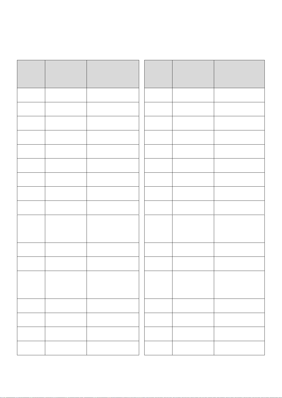
2.17 Limitation, warning, information and identification placards
The following limitation warning placards must be placed in or on the
aircraft and positioned in plain view of the pilot, passenger or third person,
as the case may be.
In a place visible to pilot and passenger:
Date of Issue: 07 July 2014 Revision : 1.3
Page | 2-15
Airplane Factory SLING LSA
FASTEN SEATBELTS
NO INTENTIONAL SPINS
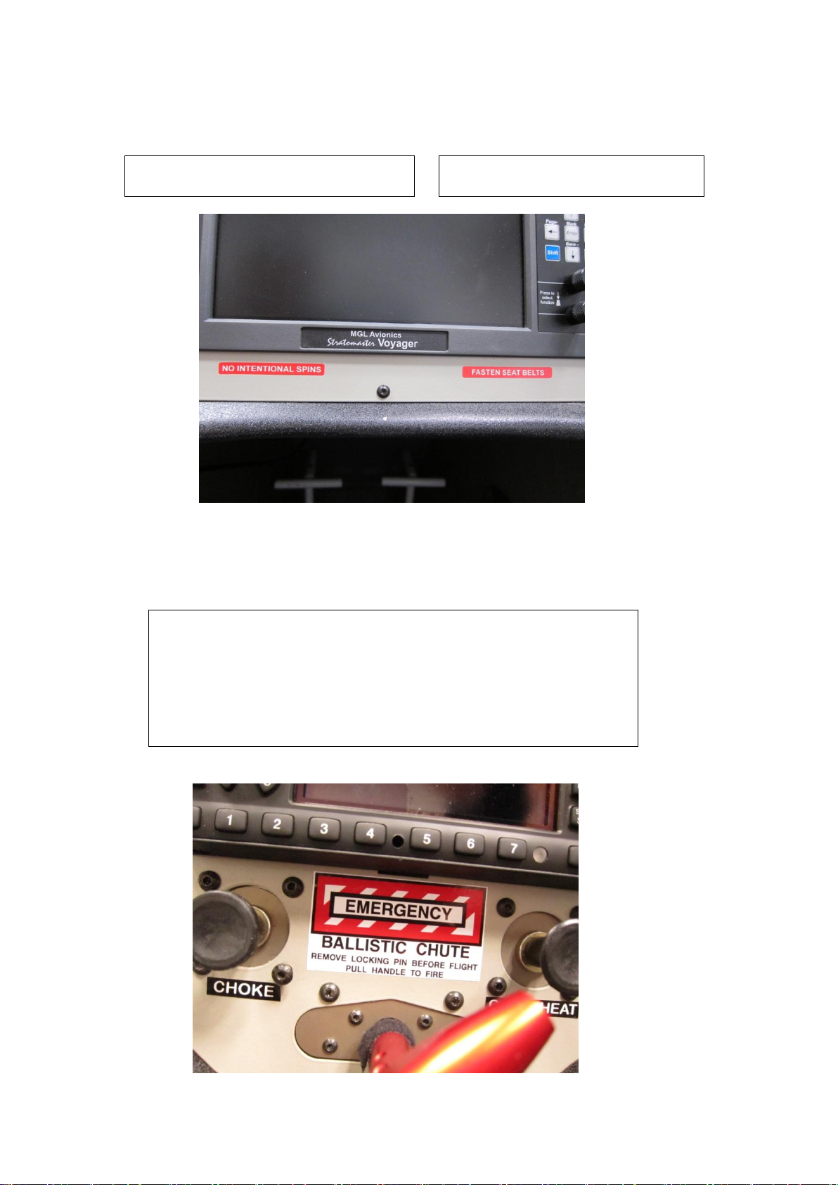
EMERGENCY
BALLISTIC CHUTE
REMOVE LOCKING PIN BEFORE FLIGHT
PULL HANDLE TO FIRE
Pilot Operating Handbook
If a ballistic rescue parachute is fitted, adjacent to the ballistic
parachute activation lever:
Date of Issue: 07 July 2014 Revision : 1.3
Page | 2-16

Airplane Factory SLING LSA
19.8 U.S. GALS.
91 OCT. MOGAS
100LL AVGAS
MAX TOTAL BAGGAGE WEIGHT – 35 KG / 77 LB
MAX FRONT SECTION 35 KG / 77LB
MAX REAR SECTION 25 KG / 55 LB
Pilot Operating Handbook
On the baggage space separator channel:
Adjacent to the fuel filler caps:
Date of Issue: 07 July 2014 Revision : 1.3
Page | 2-17

Airplane Factory SLING LSA
TIRE PRESSURE
32 P.S.I
TIRE PRESSURE
26 P.S.I
Pilot Operating Handbook
Adjacent to the filler hole in the main gear wheel pants (on each wheel):
Adjacent to the filler hole in the nose gear wheel pants:
Page | 2-18
Date of Issue: 07 July 2014 Revision : 1.3

Airplane Factory SLING LSA
NO STEP
Pilot Operating Handbook
On the inboard upper wing flap surface:
Page | 2-19
Date of Issue: 07 July 2014 Revision : 1.3

Airplane Factory SLING LSA
LIGHT-SPORT
WARNING
This aircraft is equipped with a ballistically-
deployed emergency parachute system
Pilot Operating Handbook
On the exterior of the fuselage adjacent to the entrance to the cockpit:
On both pilot and passenger sides:
If a ballistic rescue parachute is installed:
Page | 2-20
Date of Issue: 07 July 2014 Revision : 1.3

Airplane Factory SLING LSA
DANGER EXPLOSIVE EGRESS
Rocket Deployed Parachute Egress Area
STAY CLEAR
DANGER EXPLOSIVE ROCKET
Pilot Operating Handbook
If a ballistic rescue parachute is installed:
On the exterior of the fuselage, adjacent to the egress point of the
rescue parachute system:
On the parachute rocket body, inside the rocket housing:
Date of Issue: 07 July 2014 Revision : 1.3
Page | 2-21

Airplane Factory SLING LSA
AIRCRAFT IDENTIFICATION
BUILDER: THE AIRPLANE FACTORY (Pty) Ltd
MODEL: SLING
SERIAL NO: ###
MADE IN SOUTH AFRICA
Pilot Operating Handbook
On a fireproof metal plate attached to the exterior of the aircraft, aft of
the cabin:
Note: ### represents the information applicable to the specific aircraft.
The airplane must be placarded to show the identity of:
All fuses/circuit breakers.
Magneto / ignition switches.
All other switches.
Choke (if fitted).
Starter.
Trim : Nose up and down.
Flaps : Up and Down.
Date of Issue: 07 July 2014 Revision : 1.3
Page | 2-22

Airplane Factory SLING LSA
Pilot Operating Handbook
3. EMERGENCY PROCEDURES
3.1 Introduction .............................................................................................. 3-3
3.2 Speeds for emergency operations ............................................................ 3-3
3.3 Engine related emergencies ..................................................................... 3-4
3.4 Smoke and fire .......................................................................................... 3-8
3.5 Emergency landings ................................................................................ 3-12
3.6 Recovery from unintentional spin .......................................................... 3-15
3.7 Other emergencies ................................................................................. 3-16
Page | 3-1/3-2
Date of Issue: 07 July 2014 Revision : 1.3

Airplane Factory SLING LSA
SPEED
KIAS
REMARKS
VBG
Best Glide
Speed
72
The speed (at MAUW, flaps fully retracted)
which results in the greatest gliding
(horizontal) distance.
Speed for inflight engine
start
> 72
Recommended speed.
Pilot Operating Handbook
3.1 Introduction
This section provides checklists and amplified procedures for coping with
various emergencies that may arise.
Emergencies caused by aircraft or engine malfunction are extremely rare if
proper pre-flight inspections and maintenance are practiced. However,
should an emergency arise, the basic guidelines described in this section
should be considered and applied as necessary to manage the problem.
In case of emergency the pilot should remember the following priorities –
1 Keep control of and continue flying the aircraft.
2 Analyze the situation.
3 Apply applicable procedures.
4 Inform air traffic control of the situation if time and conditions
permit it.
3.2 Speeds for emergency operations
Date of Issue: 07 July 2014 Revision : 1.3
Page | 3-3

Airplane Factory SLING LSA
Pilot Operating Handbook
3.3 Engine related emergencies
3.3.1 Engine failure during take-off run
1. Throttle - idle.
2. Magnetos / ignition - off.
3. Brakes - apply as needed.
4. Master switch - off.
With airplane under control –
5. Fuel selector valve - off.
6. Auxiliary (electric) fuel pump - off (912 ULS).
Electric fuel pumps (both) - off (912 iS).
3.3.2 Engine failure immediately after take-off
1. Speed - check.
2. Find a suitable place on the ground to land safely. The landing
should be planned straight ahead with only small changes in direction
not exceeding 45 degrees to either side.
3. Flaps - as needed (plan to land as slowly
as possible).
Before touch down
4. Magnetos / ignition - off.
5. Master - off.
6. Fuel selector valve - off.
7. Electric fuel pump - off (912 ULS).
Electric fuel pumps (both) - off (912 iS).
Page | 3-4
Date of Issue: 07 July 2014 Revision : 1.3

Airplane Factory SLING LSA
Pilot Operating Handbook
3.3.3 Engine irregularities in flight
3.3.3.1 Irregular engine rpm
1. Verify magneto switches - both on.
2 Verify throttle position.
3. Verify engine and fuel quantity indicators.
4. Electric fuel pump on (912 ULS).
Auxiliary electric fuel pump on (912 iS).
If engine continues to run irregularly
5. Land as soon as possible.
3.3.3.2 Low fuel pressure (refer to engine limitations, Section 2 (912 ULS)
or 912 iS engine supplement at end of manual)
1. Check fuel quantity indicator.
2. Switch electric fuel pump on (912 ULS).
Switch auxiliary electric fuel pump on (912 iS).
If fuel pressure remains low
3. Decrease throttle setting if viable to do so.
If fuel pressure remains low
4. Land as soon as possible.
Page | 3-5
Date of Issue: 07 July 2014 Revision : 1.3

Airplane Factory SLING LSA
Pilot Operating Handbook
3.3.3.3 Low oil pressure (refer to engine limitations, Section 2 (912 ULS) or
912 iS engine supplement at end of manual)
1. Check oil temperature.
If oil temperature is high or increasing
2. Set throttle to a setting which gives an aircraft speed of 72 KIAS
(most efficient speed).
If oil pressure remains low or temperature remains high or increasing
3. Land as soon as possible and remain vigilant for impending engine
failure.
Page | 3-6
Date of Issue: 07 July 2014 Revision : 1.3

Airplane Factory SLING LSA
NOTE
It is possible that the propeller may continue to rotate if the
airspeed remains above approximately 72 KIAS. In such
circumstances no application of the starter switch may be
required. If the propeller stops rotating increasing airspeed
may result in it again starting to do so.
Pilot Operating Handbook
3.3.4 In-flight engine restart
1. Electric fuel pump - on (912 ULS).
Electric fuel pumps (both) - on (912 iS).
2. Fuel selector - open (RIGHT).
3. Throttle - set to middle position.
4. Master switch - check on.
5. Magnetos / ignition - check both on.
6. Starter - engage.
7. Electric fuel pump - off (912 ULS) (after positive start).
Auxiliary fuel pump - off (912 iS) (after positive start).
If engine should fail to restart
8. Apply forced landing without engine power procedure, according
to 3.5.1.
Page | 3-7
Date of Issue: 07 July 2014 Revision : 1.3

Airplane Factory SLING LSA
Pilot Operating Handbook
3.4 Smoke and fire
3.4.1 Engine fire on ground during engine start
1. Starter - release.
2. Fuel selector - close.
3. Electric fuel pumps (both) - off (912 iS).
4. Throttle - idle.
5. Magnetos / ignition - off.
6. Master switch - off.
7. Retrieve fire extinguisher if possible.
8. Exit the airplane.
9. Extinguish fire by fire extinguisher or call for a fire-brigade if you
cannot do it.
3.4.2 Engine fire on ground with engine running
1. Cabin heat - close.
2. Fuel selector - close.
3. Electric fuel pumps (both) - off (912 iS).
4. Throttle - idle.
5. Magnetos / ignition - off.
6. Master switch - off.
7. Retrieve fire extinguisher if possible.
8. Leave the airplane.
9. Extinguish fire by fire extinguisher or call for a fire-brigade if you
cannot do it.
Page | 3-8
Date of Issue: 07 July 2014 Revision : 1.3

Airplane Factory SLING LSA
NOTE
Estimated time to empty carburetors
after fuel selector valve is closed is
30 seconds
WARNING
Do not attempt to re-start
the engine!
Pilot Operating Handbook
3.4.3 Engine fire during take-off run
1. Throttle - idle.
2. Brakes - stop the aircraft.
3. Cabin heat - close.
4. Fuel selector - close.
5. Electric fuel pump(s) - off.
6. Magnetos / ignition - off.
8. Master switch - off.
9. Retrieve fire extinguisher if possible.
10. Exit the aircraft.
11. Extinguish the fire by fire extinguisher or call for fire services if
unable to do so.
3.4.4 Engine fire in flight
1. Heating - close.
2. Fuel selector - close.
3. Throttle - full power.
4. Magnetos / ignition - switch off after the fuel in carburetors
5. Electric fuel pumps (both) - off (912 iS).
6. Choose landing area - choose emergency landing area.
7. Emergency landing - perform according to 3.5.1.
8. Retrieve fire extinguisher if possible.
9. Exit the airplane.
10. Extinguish fire by fire extinguisher / call for fire-brigade if you
cannot do it.
is consumed and engine has shut down.
Date of Issue: 07 July 2014 Revision : 1.3
Page | 3-9

Airplane Factory SLING LSA
Pilot Operating Handbook
3.4.5 Electrical fire in flight
An electrical fire is often characterized by white smoke and an acrid
smell.
1. Master switch - off (see NOTE below).
2. Cabin heat - close.
3. Use the fire extinguisher (if possible).
4. Ventilate cabin if required / applicable (open air vents on instrument
panel).
5. If fire is extinguished consider executing a precautionary landing /
land as soon as practical.
6. If fire does not extinguish land immediately.
NOTE:
If the location / source of the electrical fire can be determined
and electrical power can be removed from that system / location
by isolating / switching the system off, do so. This may alleviate
the need to switch off the master switch.
For aircraft equipped with a 912 iS engine, refer to the applicable
supplement at the end of this manual, with regard to the Master
switch.
The EFIS and associated equipment (iBox, RDAC etc.) can still be
powered (to provide engine monitoring) from the EFIS back-up battery
circuit when the master switch is off, provided that the EFIS system is
not the location / source of the electrical fire.
Page | 3-10
Date of Issue: 07 July 2014 Revision : 1.3

Airplane Factory SLING LSA
Pilot Operating Handbook
3.4.6 Cabin fire
If the fire is electrical in nature follow the procedure for electrical fires
in flight (3.4.5).
Alternatively:
1. Cabin heat - close.
2. Use the fire extinguisher (if possible).
3. Ventilate cabin if required / applicable (open air vents on instrument
panel).
4. If fire is extinguished consider executing a precautionary landing /
land as soon as practical.
5. If fire does not extinguish land immediately.
Page | 3-11
Date of Issue: 07 July 2014 Revision : 1.3

Airplane Factory SLING LSA
WARNING
Flaps and elevator trim cannot operate without power on the main bus.
Make final flap selection before turning master switch off.
Pilot Operating Handbook
3.5 Emergency landings
Emergency landings are generally carried out in the case of engine failure
during which the engine cannot be re-started. Other reasons for an
emergency landing may, however, arise.
3.5.1 Engine-off emergency landing
1. Speed - best glide speed of 72 KIAS.
2. Trim - trim for best glide speed.
3. Landing location - locate most suitable landing location,
free of obstacles and preferably into
wind.
4. Safety harness - tighten.
5. Engine restart - if time permits and if appropriate
attempt to identify reason for engine
failure and attempt restart.
6. Flaps - extend as needed.
7. Communications - report your location to third parties if
possible.
8. Passenger - brief.
Immediately before touchdown-
9. Fuel selector - shut off.
10. Electric fuel pump - off (912 ULS).
Electric fuel pumps (both) - off (912 iS).
11. Magnetos / ignition - off.
12. Master switch - off.
Page | 3-12
Date of Issue: 07 July 2014 Revision : 1.3

Airplane Factory SLING LSA
NOTE
Keep the chosen area in sight during
precautionary landing.
Pilot Operating Handbook
3.5.2 Precautionary landing
A precautionary landing is generally carried out in cases where the pilot
may be disorientated, the aircraft has no fuel reserve or possibly in bad
weather conditions.
1. Choose landing area, determine wind direction.
2. Report your intention to land and the landing location via radio.
3. Perform a low altitude pass into wind, over the right-hand side of
the selected area, with flaps extended as required and thoroughly
inspect the landing area.
4. Perform a circuit pattern.
5. Perform approach at increased idle with flaps fully extended.
6. Reduce power to idle when flying over the runway threshold and
touch-down at the very beginning of the selected area.
7. After stopping the aircraft switch off all switches, shut off the fuel
selector, lock the aircraft and seek assistance.
Page | 3-13
Date of Issue: 07 July 2014 Revision : 1.3

Airplane Factory SLING LSA
Pilot Operating Handbook
3.5.3 Landing with a flat tire / damaged wheel
1. If a main landing gear tire is flat or a wheel is damaged, perform
touch-down at the lowest practical speed with the aircraft slightly
banked towards the serviceable tire / wheel. Maintain directional
control during the landing run and keep the flat tire / damaged
wheel off the ground, just above or very lightly on the ground, until
the lowest speed possible.
2. If the nose wheel is damaged / flat perform touch-down at the
lowest practical speed and hold the nose wheel off the ground as
long as possible, via elevator control.
Page | 3-14
Date of Issue: 07 July 2014 Revision : 1.3

Airplane Factory SLING LSA
WARNING
Intentional spins are prohibited!
NOTE
Notwithstanding that installed equipment may
include GPS navigational aids, such equipment may
not be used as the sole information source for
purposes of navigation unless permitted by law.
Pilot Operating Handbook
3.6 Recovery from unintentional spin
The aircraft is unlikely to enter an unintentional spin unless extreme
control are applied.
Unintentional spin recovery technique:
1. Throttle - idle.
2. Lateral control - ailerons neutral.
3. Rudder pedals - full rudder in direction opposite to spin
4. Rudder pedals - neutralize rudder immediately when
rotation stops.
5. Longitudinal control - neutralize control column or push
forward if necessary to lower nose, then
recover from dive ensuring VNE and load
factor limitations are not exceeded.
In the unlikely event that applied control inputs result in the aircraft
entering a flat spin and the steps listed above do not result in recovery
(following their application for a sustained period), the following
technique may be implemented:
1. Throttle - set to full power.
2. Lateral control - ailerons neutral.
3. Rudder pedals - full rudder in direction opposite to spin.
4. Rudder pedals - neutralize rudder immediately when
rotation stops.
5. Throttle - reduce to idle.
6. Longitudinal control - as per step 5 (longitudinal control) above.
Date of Issue: 07 July 2014 Revision : 1.3
Page | 3-15

Airplane Factory SLING LSA
Pilot Operating Handbook
3.7 Other emergencies
3.7.1 Vibration
If any abnormal aircraft vibration occurs:
1. Set engine speed to a setting where the vibration is least, if viable.
2. Land on the nearest airfield or perform a precautionary landing
according to 3.5.2.
3.7.2 EFIS System Failure
If the EFIS system freezes, otherwise fails or reacts incorrectly in flight:
1. Maintain straight and level flight utilizing other instruments and
ground references.
2. Switch the EFIS back-up battery and the EFIS main switch off (i.e.
remove power from the EFIS).
3. Following a 3 second delay, apply power to the EFIS, maintaining
straight and level flight at all times.
4. Maintain straight and level for at least another 15 seconds while the
system boots up (when the system reboots, the navigation system(s)
should remain active and any active routes (preceding the failure)
should continue to be shown).
In case the system fails to re-boot properly:
5. Execute a precautionary landing at the first safe opportunity and
have the instrument repaired.
Page | 3-16
Date of Issue: 07 July 2014 Revision : 1.3

Airplane Factory SLING LSA
Pilot Operating Handbook
3.7.3 Carburetor icing
Carburetor icing is evidenced through a decrease in engine power and
an increase of engine temperatures.
To recover the engine power, the following procedure is
recommended:
1. Speed - 75 KIAS
2. Throttle - 1/3 power.
3. If possible leave the (icing) area.
4. Increase the engine power gradually up to cruise conditions after
1 to 2 minutes.
If you fail to recover engine power, land on the nearest airfield (if
possible) or, depending on the circumstances, perform a precautionary
landing according to 3.5.2.
Page | 3-17
Date of Issue: 07 July 2014 Revision : 1.3

Airplane Factory SLING LSA
NOTE
The 912 ULS engine operation is independent from the aircraft
main battery (except for start motor operation) / alternator. The
engine will continue running after an alternator / charge system
failure and / or with a depleted battery.
Pilot Operating Handbook
3.7.4 Alternator / charge system failure
For aircraft fitted with the 912 iS engine please refer to the supplement
at the end of this manual.
Alternator failure (912 ULS) is evidenced by the illumination of the (red)
alternator / charge warning light.
1. EFIS switch - off.
2. All non-critical electrical equipment - off.
(navigation, strobe, taxi, landing lights etc.).
3. Auxiliary fuel pump - off.
4. Autopilot - off.
5. Set EFIS brightness to minimum.
6. Restrict / avoid the use of the elevator trim control. Restrict radio
transmission to minimum / only that which is absolutely necessary.
7. Land as soon as possible.
Date of Issue: 07 July 2014 Revision : 1.3
Page | 3-18

Airplane Factory SLING LSA
Pilot Operating Handbook
3.7.5 Main bus power failure
Refer to paragraph 7.17, under Main bus, for a list of equipment
affected by a loss of power to the main bus.
1. The EFIS should automatically switch over to the EFIS back-up battery
supply , provided that the EFIS battery back-up switch is on (if not,
switch on the EFIS battery back-up switch) and the back-up battery
contains adequate charge.
2. Land as soon as possible.
Page | 3-19
Date of Issue: 07 July 2014 Revision : 1.3

Airplane Factory SLING LSA
Pilot Operating Handbook
4. NORMAL PROCEDURES
4.1 Introduction .............................................................................................. 4-3
4.2 Speeds for normal operation .................................................................... 4-3
4.3 Use of taxi, landing, strobe and navigation lights ..................................... 4-4
4.4 Pre-flight check ......................................................................................... 4-5
4.5 Engine start ............................................................................................. 4-10
4.6 Taxi ......................................................................................................... 4-11
4.7 Normal take-off ...................................................................................... 4-12
4.8 Climb....................................................................................................... 4-14
4.9 Cruise ...................................................................................................... 4-15
4.10 Descend ............................................................................................... 4-15
4.11 Approach ............................................................................................. 4-16
4.12 Normal landing .................................................................................... 4-17
4.13 Baulked landing procedures ................................................................. 4-18
4.14 Short field take-off and landing procedures ........................................ 4-18
4.15 Engine shutdown ................................................................................. 4-19
4.16 Aircraft parking and tie-down .............................................................. 4-20
Page | 4-1/4-2
Date of Issue: 07 July 2014 Revision : 1.3

Airplane Factory SLING LSA
SPEED
KIAS
REMARKS
Vx
Best Angle of
Climb Speed
65
The speed (at MAUW, flaps fully retracted)
which results in the greatest altitude gain
over a given horizontal distance (i.e.
largest climb angle).
VY
Best Rate of
Climb Speed
72
The speed (at MAUW, flaps fully retracted)
which results in the greatest altitude gain
over a given time period.
V
ROT
Rotation
Speed
40
The speed at which the aircraft should be
rotated about the pitch axis during takeoff (i.e. the speed at which the nose wheel
is lifted off the ground).
V
LOF
Lift-off
Speed
48
The speed at which the aircraft generally
lifts off from the ground during take-off.
Cruise Climb
75 to 90
Approach
speed - long
finals
65 to 75
V
REF
Threshold
crossing
speed
≥ 52
Indicated airspeed at 15 m (50 ft) above
threshold, which is not less than 1.3VSO.
Pilot Operating Handbook
4.1 Introduction
This section provides checklists and recommended procedures for normal
operation of the airplane.
4.2 Speeds for normal operation
Unless otherwise noted, the following speeds are based on a maximum
weight of 600 kg (1320 lb).
Date of Issue: 07 July 2014 Revision : 1.3
Page | 4-3

Airplane Factory SLING LSA
Pilot Operating Handbook
4.3 Use of taxi, landing, strobe and navigation lights
Taxi lights should be used as appropriate and their use should be
incorporated in the applicable (taxi and before take-off) procedures as
required. Give consideration to taxi lights as an aid to enhancing the
aircraft’s visibility to other traffic / pedestrians / wildlife.
Landing lights should be used as appropriate and their use should be
incorporated in the applicable (before take-off, take-off, climb, approach
and landing) procedures as required. Give consideration to landing lights
as an aid to enhancing the aircraft’s visibility to other traffic / pedestrians /
wildlife.
Strobe and navigation lights should be used as appropriate and their use
should be incorporated in the following (normal) procedures as required.
Give consideration to using the strobe light as an indicator / warning of
imminent engine start (i.e. switch on the strobe before starting the
engine).
Page | 4-4
Date of Issue: 07 July 2014 Revision : 1.3

Airplane Factory SLING LSA
NOTE
The word “condition” in the instructions means a visual
inspection of surface for damage deformations,
scratching, chafing, corrosion or other damages, which
may lead to flight safety degradation.
Pilot Operating Handbook
4.4 Pre-flight check
Carry out the pre-flight inspection every day prior to the first fight. Preflight inspections must also be performed after any accident, incident,
maintenance activity, assembly of any aircraft component or suchlike.
Incomplete or careless inspection can result in an accident. Carry out the
inspection following the instructions in the Inspection Check List.
Inspection check List
1. Cabin
- Magnetos / ignition - off.
- Master switch - on
- Fuel level indicator - verify fuel quantity.
- Flaps - move to full down position.
- Master switch - off.
- Avionics - verify condition.
- Control System - visual inspection, free movement up to
stops, verify function.
- Canopy - attachment condition, clean.
- Cockpit - check for loose objects.
- Fire extinguisher - verify present and valid.
- Documentation - verify present and valid.
Page | 4-5
Date of Issue: 07 July 2014 Revision : 1.3

Airplane Factory SLING LSA
CAUTION
In case of long-term parking it is recommended to turn the engine
over several times (Ignition OFF!) by turning the propeller in order
to prime the lubrication system. Always handle the propeller blade
area with the palm of your hand i.e. do not grasp only the blade
edge with your fingers.
Pilot Operating Handbook
2. Nose Section and Nose Gear
- Engine cowling condition - check.
- Propeller and spinner condition - check.
- Air intakes - check.
- Radiators - check.
- Engine mount and exhaust manifold condition- check.
- Oil and coolant quantity check - check.
- Visual inspection of fuel and electrical system- check.
- Engine checks as per Rotax manual - complete.
- Other actions according to the engine manual
- Parachute cover - if fitted check sealed
- Tire - condition, inflation,
- Wheels - security, general
- Chocks and tie-down ropes - remove.
- Suspension and undercarriage - check and test.
and secure.
wear.
condition.
Date of Issue: 07 July 2014 Revision : 1.3
Page | 4-6

Airplane Factory SLING LSA
WARNING
Physically verify the fuel level before each take-off
to make sure you have sufficient fuel for the
planned flight.
Pilot Operating Handbook
3. Right Fuselage
- Surface condition - check.
- Cowling attachment - check.
- Wing/fuselage fairings - check.
- Empennage fairings - check.
- Antenna/e - check condition and security.
4. Right Wing and Main Gear
- Wheel fairing - security, cracks.
- Wheel and brakes - fluid leaks, security, general
condition, tire condition, inflation
and wear.
- Wheel strut - condition, cracks.
- Leading edge condition - check.
- Taxi / landing lights and lens - check for cracks and condition.
- Fuel vent (underside of wing) - unobstructed.
- Wing trailing edge - check condition.
- Aileron - freedom of movement,
attachment, surface condition.
- Aileron hinges, control horn, bolts, pushrod - secure, condition.
- Flap hinges, control horn, bolts, pushrod - secure, condition.
- Wing tip - check condition.
- Strobe/Nav light and lens - check for cracks and condition.
Date of Issue: 07 July 2014 Revision : 1.3
Page | 4-7

Airplane Factory SLING LSA
Pilot Operating Handbook
5. Empennage
- Tie-down rope - removed.
- Horizontal and vertical stabilizers - check condition.
- Elevator and tab - condition and movement.
- Rudder - condition and movement.
- Hinges, control horns, bolts, pushrod - condition and secure.
6. Left Fuselage
- Surface condition - check.
- Cowling attachment - check.
- Wing/fuselage fairings - check.
- Empennage fairings - check.
- Antenna/e - check condition and security.
Page | 4-8
Date of Issue: 07 July 2014 Revision : 1.3

Airplane Factory SLING LSA
Pilot Operating Handbook
7. Left Wing
- Wheel fairing - security, cracks.
- Wheel and brakes - fluid leaks, security, general
condition, tire condition, inflation
and wear.
- Wheel strut - condition, cracks.
- Leading edge condition - check.
- Taxi / landing lights and lens - check for cracks and condition.
- Fuel vent (underside of wing) - unobstructed
- Wing trailing edge - check condition.
- Aileron - freedom of movement,
attachment, surface condition.
- Aileron hinges, control horn, bolts, pushrod - secure, condition.
- Flap hinges, control horn, bolts, pushrod - secure, condition.
- Wing tip - check condition.
- Strobe/Nav light and lens - check for cracks and condition.
- Pitot tube - security, unobstructed, remove
cover.
Page | 4-9
Date of Issue: 07 July 2014 Revision : 1.3

Airplane Factory SLING LSA
CAUTION
In case of long-term parking it is recommended to turn the engine
over several times (Ignition / magnetos OFF!) by turning the
propeller in order to prime the lubrication system. Always handle
the propeller blade area with the palm of your hand i.e. do not
grasp only the blade edge with your fingers.
CAUTION
Observe the temperature limits for engine start as specified in
paragraph 2.14.
Pilot Operating Handbook
4.5 Engine start
Reference should be made to the operator’s manual for the Rotax
912 iS or 912 ULS engine, as the case may be, for operational guidelines
and instructions. These should be incorporated into the normal or
emergency procedures as applicable.
4.5.1 Before starting engine
1. Pre-flight inspection - completed.
2. Emergency equipment - on board.
3. Passenger - briefed.
4. Seats, seatbelt and harnesses - adjust and secure.
5. Brakes - on.
Date of Issue: 07 July 2014 Revision : 1.3
Page | 4-10

Airplane Factory SLING LSA
Pilot Operating Handbook
4.5.2 Engine start
If a Rotax 912 iS engine is installed rather than a Rotax 912 ULS engine,
please refer to the supplement at the end of this manual.
1. Master switch - on.
2. EFIS back-up battery - on, verify EFIS on and back-up
battery voltage.
3. Magneto / ignition switches - on.
4. Fuel selector - open (RIGHT).
5. Electric fuel pumps (both) -on (912 iS).
6. Choke (cold engine) - pull to open and gradually release
7. Throttle - closed if choke used, cracked just
8. Propeller area - clear of people and obstructions.
9. Starter - engage (maximum 10 seconds).
Immediately after start-up:
10. Throttle - adjust for smooth running
11. Oil pressure - increase within 10 seconds.
12. EFIS switch - on and verify battery charging.
after engine start (912 ULS).
open if not.
(approximately 2000 rpm).
Page | 4-8
Date of Issue: 07 July 2014 Revision : 1.3

Airplane Factory SLING LSA
CAUTION
The starter should be activated for a maximum of 10 seconds, followed by 2 minute pause
to allow the starter to cool.
Verify the oil pressure, which should increase within 10 seconds. Increase the engine
speed only if oil pressure is steady above 2 bar (29 psi).
At an engine start with low oil temperature continue to watch the oil pressure as it could
drop again due to the increased resistance in the suction line. Increase engine rpm only as
required to keep oil pressure steady.
To avoid shock loading, start the engine with the throttle lever set to idle or 10% open at
maximum, then wait 3 seconds for engine to reach constant speed before accelerating
engine rpm.
Pilot Operating Handbook
13. Avionics master switch - on.
14. Warm engine - 2 000 rpm for 2 minutes, then
2 500 rpm until oil temp is 50 °C
(122 °F).
Date of Issue: 07 July 2014 Revision : 1.3
Page | 4-9

Airplane Factory SLING LSA
NOTE
Only one ignition circuit (at a time) should be switched on/off
during ignition/magneto check.
CAUTION
The engine check should be performed with the aircraft heading
upwind and not on loose terrain (the propeller may suck grit
which can damage the leading edges of blades).
Pilot Operating Handbook
4.5.3 Engine warm up, engine check
Prior to an engine check, block the main wheels with wheel chocks or
ensure that the park brake is on.
Initially warm up the engine at 2 000 rpm for approximately 2 minutes,
then continue at 2 500 rpm until oil temperature reaches 50°C (122°F).
The warm up period depends on ambient air temperature.
Verify both ignition circuits at 4 000 rpm (912 ULS). The engine speed
(rpm) drop when either magneto is switched off should not exceed 300
rpm (912 ULS). The maximum difference (in rpm drop) between
magnetos / ignition circuits should not exceed 115 rpm (912 ULS).
For verification of ignition circuits on an aircraft fitted with a 912 iS
engine, refer to the applicable supplement at the end of this manual.
Set maximum power for verification of maximum engine speed (rpm)
with given propeller and engine parameters (temperatures and
pressures).
Check acceleration from idle to maximum power.
If necessary, cool the engine at 3 000 rpm (approximately 2 minutes)
before shutdown.
Date of Issue: 07 July 2014 Revision : 1.3
Page | 4-10

Airplane Factory SLING LSA
Pilot Operating Handbook
4.6 Taxi
1. Flaps - up.
2. Brakes - off (carefully verify that the stop brake
valve (park brake) is off).
3. Controls - neutral position, or as required for wind.
4. Power and brakes - as required.
5. Brakes -verify.
6. Instruments -verify.
Apply power and brakes as needed. Apply brakes to control movement on
ground. Taxi carefully when wind velocity exceeds 15 knots. Hold the
control stick in neutral position or as required, using conventional
techniques.
Page | 4-11
Date of Issue: 07 July 2014 Revision : 1.3

Airplane Factory SLING LSA
Pilot Operating Handbook
4.7 Normal take-off
4.7.1 Before take-off
1. Controls - verify full and free movement,
directions.
2. Trim - neutral.
3. Choke - off (912 ULS).
4. Flaps - as required (typically 1 notch).
5. Fuel quantity - confirm.
6. Fuel selector - open (RIGHT).
7. Electric fuel pump - on (912 ULS).
Auxiliary electric fuel pump - on (912 iS).
8. Circuit breakers - all in.
9. Instruments - verify all.
10 Altimeter - set QNH / QFE.
11. Switches -verify, as required.
12. Power and ignition - verify magnetos at 4 000rpm, max
diff 115 rpm, max drop 300 rpm
(912 ULS).
13. Engine parameters - verify temperatures, pressures,
current/voltage.
14. Canopy - closed and latched.
15. Safety harnesses - on and tight.
16.Ballistic parachute (if fitted) - remove.
handle lock pin.
Page | 4-12
Date of Issue: 07 July 2014 Revision : 1.3

Airplane Factory SLING LSA
CAUTION
Ensure that engine oil temperature is above 50 °C prior to
take off.
Climbing with engine at 5 800 rpm is permissible for
5 minutes. Thereafter a maximum continuous engine rpm
of 5 500 applies.
WARNING
Take-off is prohibited if:
The engine is running unsteadily or intermittently.
The engine parameters (instrument indications) are
outside operational limits.
The crosswind velocity exceeds permitted limits (see 2.5).
Pilot Operating Handbook
4.7.2 Take-off
1. Take-off power - throttle fully forward (max. 5 800
rpm for 5 minutes).
2. Engine speed - verify rpm (5 500 to 5 800 rpm).
3. Instruments within limits - verify.
4. Rotate - 40 KIAS.
5. Airplane lift-off - 48 KIAS.
6. Wing flaps - retract when speed of 65 KIAS is
reached, at minimum height of
300 ft.
7. Electric fuel pump - off (912 ULS)(minimum 300 ft)
Auxiliary electric fuel pump - off (912 iS)(300 ft minimum)
8. Brakes - apply briefly to stop wheel
rotation.
9. Transition to climb.
Date of Issue: 07 July 2014 Revision : 1.3
Page | 4-13

Airplane Factory SLING LSA
CAUTION
If the cylinder head temperature or oil temperature approach
their limits, reduce the climb angle to increase airspeed and
thus fulfill the limits.
CAUTION
Climbing with engine at 5 800 rpm is permissible for
5 minutes. Thereafter a maximum continuous engine rpm
of 5 500 applies.
Pilot Operating Handbook
4.8 Climb
1. Throttle - Maximum take-off power, 5 800 rpm (for
maximum 5 minutes).
- Maximum continuous power, 5 500 rpm.
2. Airspeed - VX = 65 KIAS.
- VY = 72 KIAS.
- cruise climb = 75 to 90 KIAS.
3. Trim - as required.
4. Instruments -verify:
- oil temperature and pressure.
- cylinder temperature within limits.
Date of Issue: 07 July 2014 Revision : 1.3
Page | 4-14

Airplane Factory SLING LSA
WARNING
The fuel lift pipe in each fuel tank is situated adjacent to the lower inside
wall of the tank. The aircraft should at no time be subjected to a
sustained side slip towards a near empty fuel tank (i.e. - wing with near
empty tank down) as, despite the baffling, this may have the
consequence that the fuel runs towards the outer edge of the tank
exposing the fuel lift pipe (to suck air), thereby starving the engine of fuel
leading to engine stoppage. This poses a particular threat when at low
altitude, typically prior to landing.
WARNING
If a fuel lift pipe is exposed to air, the pump will suck air into the engine
(from the empty tank) and engine failure will result. When one tank is
empty, or close to empty, the fuel selector valve should be switched to the
fullest tank.
Avoid operation below the normal operational oil temperature (90 to
110 °C / 194 to 230 °F).
CAUTION
It is not advisable to reduce the engine throttle control lever to minimum
on final approach or when descending from very high altitude. In such
cases the engine can become over-cooled, although unlikely, and a loss
of power may occur. Descent at increased idle (approximately 3000 rpm),
speed between 65 to 85 KIAS and verify that the engine instruments
indicate values within permitted limits.
Pilot Operating Handbook
4.9 Cruise
Refer to section 5 for recommended cruising figures.
4.10 Descend
Optimum glide speed - 72 KIAS.
Date of Issue: 07 July 2014 Revision : 1.3
Page | 4-15

Airplane Factory SLING LSA
CAUTION
It is not advisable to reduce the engine throttle control lever to
minimum on final approach and when descending from very high
altitude. In such cases the engine can become over-cooled, although
unlikely, and a loss of power may occur. Descent at increased idle
(approximately 3000 rpm), speed between 65 to 85 KIAS and verify that
the engine instruments indicate values within permitted limits.
Pilot Operating Handbook
4.11 Approach
1. Approach speed
Long finals - 65 to 75 KIAS.
Short finals - ≥ 52 KIAS.
2. Electric fuel pump - on (912 ULS).
Auxiliary electric fuel pump - on (912 iS).
3. Fuel selector - open (RIGHT).
4. Throttle - as required.
5. Wing flaps - extend as required.
6. Trim - as needed.
7. Brakes - off (carefully check that the brake
stop-valve is off).
Date of Issue: 07 July 2014 Revision : 1.3
Page | 4-16

Airplane Factory SLING LSA
CAUTION
Rapid engine cooling should be avoided during operation. This especially
happens during aircraft descent, taxi, low engine rpm or at engine
shutdown immediately after landing. Under normal conditions the engine
temperatures stabilize during descent and taxi at values suitable to stop
the engine (by switching the ignition off) as soon as aircraft is stopped. If
necessary (elevated engine operating temperatures), cool (for minimum
2 minutes) the engine at approximately 3 000 rpm to stabilize the
temperatures prior to engine shut down.
Pilot Operating Handbook
4.12 Normal landing
4.12.1 Before landing
1. Throttle - as required.
2. Airspeed - ≥ 52 KIAS.
3. Wing flaps - extend as required.
4. Trim - as required.
4.12.2 Landing
1. Throttle - idle.
2. Controls - flare to minimum flying speed.
3. Touch-down on main wheels.
4. Apply brakes - as required (after the nose wheel
4.12.3 After landing
1. Engine speed - set as required for taxi.
2. Wing flaps - retract.
touched down).
Date of Issue: 07 July 2014 Revision : 1.3
Page | 4-17

Airplane Factory SLING LSA
Pilot Operating Handbook
4.13 Baulked landing procedures
1. Throttle - full power (maximum 5 800 rpm for
5 minutes).
2. Trim - as required.
3. Wing flaps - retract to 50% as soon as possible and
retract fully when reaching 65 KIAS (at
300 ft minimum height).
4. Electric fuel pump - off (912 ULS) (300 ft minimum).
Auxiliary electric fuel pump - off (912 iS) (300 ft minimum).
5. Trim - adjust.
6. Repeat circuit pattern.
4.14 Short field take-off and landing procedures
Not considered necessary. Ordinary short field procedures may be used if
pilot deems it appropriate.
Page | 4-18
Date of Issue: 07 July 2014 Revision : 1.3

Airplane Factory SLING LSA
CAUTION
Rapid engine cooling should be avoided during operation. This especially
happens during aircraft descent, taxi, low engine rpm or at engine
shutdown immediately after landing. Under normal conditions the engine
temperatures stabilize during descent and taxi at values suitable to stop
the engine (by switching the ignition off) as soon as aircraft is stopped. If
necessary (elevated engine operating temperatures), cool (for minimum 2
minutes) the engine at approximately 3 000 rpm to stabilize the
temperatures prior to engine shut down.
Pilot Operating Handbook
4.15 Engine shutdown
For Rotax 912 iS engine at least 5 minutes must elapse between
landing and shutting off the engine.
1. Engine speed - idle.
2. Instruments - engine parameters within limits.
3. Avionics master switch - off.
4. Electric fuel pump - off (912 ULS).
Electric fuel pumps (both) - off (912 iS).
5. Magnetos / ignition - off.
6. Switches - off.
7. EFIS - off, battery back-up off.
8. Master switch - off.
9. Fuel selector - off.
Date of Issue: 07 July 2014 Revision : 1.3
Page | 4-19

Airplane Factory SLING LSA
NOTE
Use the anchor eyes on the wings and fuselage rear section to secure the
airplane. Move control stick forward and secure it together with the
rudder pedals if high winds are expected. Make sure that the cockpit
canopy is properly closed and locked.
NOTE
It is recommended that the parking brake (shutoff valve) be utilised for
short-period parking only. If the airplane is to be parked for long periods it
is advisable to use not only the parking brake, but also wheel chocks.
Pilot Operating Handbook
4.16 Aircraft parking and tie-down
1. Site - Park the aircraft on as level an area as
possible.
2. Ignition/ magnetos -off.
3. Master switch -off.
4. Fuel selector -off.
5. Parking brake - use as necessary.
6. Canopy - close, lock as necessary.
7. Secure the airplane.
Date of Issue: 07 July 2014 Revision : 1.3
Page | 4-20

Airplane Factory SLING LSA
Pilot Operating Handbook
5. PERFORMANCE
5.1 Take-off and landing distance ................................................................... 5-3
5.2 Rate of climb ............................................................................................. 5-4
5.3 Cruise speeds (with fixed pitch propeller) ................................................ 5-5
5.4 Fuel consumption ..................................................................................... 5-6
5.5 Airspeed indicator system calibration ...................................................... 5-7
Page | 5-1/5-2
Date of Issue: 07 July 2014 Revision : 1.3

Airplane Factory SLING LSA
Surface
Take-off run
Take-off distance over 15m (50 ft) obstacle
Concrete
120 m / 395ft
230 m / 755 ft
Grass
140 m / 460 ft
250 m / 820 ft
Surface
Landing run
distance (braked)
Landing distance over 15 m (50 ft) obstacle
Concrete
80 m / 265 ft
250 m / 820 ft
Grass
80 m / 265 ft
250 m / 820 ft
Pilot Operating Handbook
The presented data has been computed from actual flight tests with the
aircraft and engine in good condition and using average piloting techniques.
If not stated otherwise, the performance stated in this section is valid for
maximum take-off weight (600 kg/1320 lb) and under ISA conditions.
The performance shown in this section is valid for aircraft fitted with a
ROTAX 912 ULS 73.5kW (98.6 hp) engine or a ROTAX 912 iS 73.5kW
(98.6 hp) engine with a 72 inch, 3 blade, fixed pitch, Warp drive composite
propeller.
5.1 Take-off and landing distance
Take-off distances:
Landing distances:
Page | 5-3
Date of Issue: 07 July 2014 Revision : 1.3

Airplane Factory SLING LSA
Conditions:
Max. continuous power : 5 500 rpm
Weight : 600 kg / 1320 lb
Best rate of climb speed
(VY)
Rate of
climb
KIAS
fpm
0 ft ISA
72
800
3 000 ft ISA
72
600
6 000 ft ISA
72
500
9 000 ft ISA
72
400
Pilot Operating Handbook
5.2 Rate of climb
Date of Issue: 07 July 2014 Revision : 1.3
Page | 5-4

Airplane Factory SLING LSA
Altitude
[ft ISA]
Engine
speed
[rpm]
KIAS
KTAS
100
4 500
81
82
4 800
95
96
5 000
101
102
5 300
106
108
5 500
112
114
3 000
4 500
72
76
4 800
87
91
5 000
98
104
5 300
104
109
5 500
108
114
6 000
4 500
65
73
4 800
80
89
5 000
90
100
5 300
98
108
5 500
101
115
9 000
4 500
63
73
4 800
74
88
5 000
87
99
5 300
91
105
5 500
94
108
Pilot Operating Handbook
5.3 Cruise speeds (with fixed pitch propeller)
Date of Issue: 07 July 2014 Revision : 1.3
Page | 5-5

Airplane Factory SLING LSA
Altitude
[ft ISA]
3 000
Fuel
quantity
[ l ]
150
[US gallons]
39.6
Engine
speed
[rpm]
4 500
4 800
5 000
5 300
5 500
Fuel
consumption
[l/h]
14
16
18
20
21
[US gallons]
3.7
4.2
4.8
5.3
5.5
Airspeed
[KIAS]
73
91
104
109
114
Endurance
[hh:mm]
10:40
9:20
08:20
07:30
07:10
Range
(no reserve)
[nm]
781
853
866
817
815
Pilot Operating Handbook
5.4 Fuel consumption
Date of Issue: 07 July 2014 Revision : 1.3
Page | 5-6

Airplane Factory SLING LSA
IAS [knots]
CAS [knots]
(average)
CAS [knots]
(this aircraft)
25
28
30
33
35
38
40
44
45
45
50
50
55
55
60
60
65
65
70
70
75
75
80
80
85
85
90
90
95
95
100
100
105
105
110
110
115
115
120
120
125
125
130
130
135
135
Pilot Operating Handbook
5.5 Airspeed indicator system calibration
Page | 5-7
Date of Issue: 07 July 2014 Revision : 1.3

Airplane Factory SLING LSA
Pilot Operating Handbook
6. WEIGHT AND BALANCE
6.1 Installed equipment list ............................................................................ 6-3
6.2 Center of gravity (CG) range ..................................................................... 6-4
6.3 Determination of CG ................................................................................. 6-6
6.4 Empty CG determination .......................................................................... 6-7
6.5 Blank form and graph for use ................................................................... 6-8
Page | 6-1/6-2
Date of Issue: 07 July 2014 Revision : 1.3

Airplane Factory SLING LSA
Pilot Operating Handbook
This section contains weight and balance records and the payload range for
safe operating of the Sling LSA.
6.1 Installed equipment list
MGL multifunction glass cockpit instrument - Challenger iEFIS.
MGL V6 COM radio.
Mode S transponder (optional).
Analogue altimeter, airspeed indicator, ball type slip indicator.
Magnetic compass.
Electric trim system.
Electric flap actuator.
Page | 6-3
Date of Issue: 07 July 2014 Revision : 1.3

Airplane Factory SLING LSA
GC range is 1 635 mm (5.364 ft) to 1 772 mm (5.814 ft) aft of the reference
datum (20 to 30.3% of MAC).
The leading edge of the MAC is 1 366 mm (4.482 ft) aft of the reference
datum.
The MAC is 1 339 mm (4.393 ft).
WARNING
Aircraft CG and MAUW limitations must be adhered
to at all times.
DIMENSIONS IN THIS DRAWING
ARE IN FEET
Pilot Operating Handbook
6.2 Center of gravity (CG) range
Operating CG range and allowable GC envelope
Page | 6-4
Date of Issue: 07 July 2014 Revision : 1.3
 Loading...