

Page 1
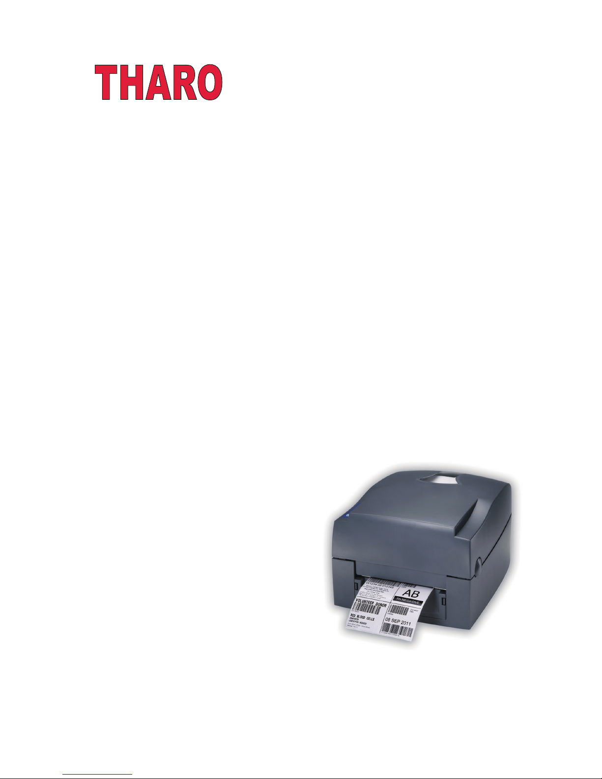
V-425E and V-434E
Users Manual
Date: 01-26-2015
Page 2

CONTENTS
1
Barcode Printer
1
1.1
1.2
Box Contents
Getting to Know Your Printer
1
2
2
Printer Setup
4
2.1
2.2
2.3
2.4
2.5
Opening the Top Cover
Opening the Print Mechanism
Loading Ribbon the Host Computer
Loading Labels
4
4
5
3
Printer Setting and Control
17
3.1
3.2
3.3
Operation Panel
Label Calibration and Self-Test
Error Alerts
17
18
19
4
NetSetting for Ethernet
4.1
4.2
Installing the NetSetting Software
NetSetting Interface
20
21
5
Accessories
28
5.1
5.2
5.3
Preparation
Installing the Label Dispenser
Installing the Cutter
28
29
6
Maintenance and Adjustment
38
6.1
6.2
6.3
6.4
6.5
Cleaning the Thermal Print Head
Adjusting the Print Head Pressure
Adjusting the Print Line
Clearing Cutter jams
Troubleshooting
38
38
39
39
40
Appendix
Label Supply Hub Installation
9
7
34
41
Product Specifications
Interface Specifications
41
42
20
2.6
2.7
2.8
2.9
10
11
12
15
Preparation for Tag Printing
Connection the Printer to your Computer
EASYLABEL Start Installation
Windows Driver Installation
Page 3

FCC COMPLIANCE STATEMENT
FOR AMERICAN USERS
This equipment has been tested and found to comply with the limits for a CLASS A digital device, pursuant to Part
15 of the FCC Rules. These limits are designed to provide reasonable protection against harmful interference
when the equipment is operated in a commercial environment. This equipment generates, uses, and can radiate
radio frequency energy and, if not installed and used in accordance with the instructions, may cause harmful
interference to radio communications. Operation of this equipment in a residential area is likely to cause harmful
interference in which case the user will be required to correct the interference at their own expense.
EMS AND EMI COMPLIANCE STATEMENT
FOR EUROPEAN USERS
This equipment has been tested and passed with the requirements relating to electromagnetic compatibility
based on the standards EN 55022:2006/A1:2007 Class A, EN61000-3-2:2006, EN 61000-3-3:2008 and
EN55024:1998/A1:2001/A2:2003, IEC 61000-4-2:2008 series, The equipment also tested and passed in
accordance with the European Standard EN55022 for the both Radiated and Conducted emissions limits.
V-400E SERIES
TO WHICH THIS DECLARATION RELATES
IS IN CONFORMITY WITH THE FOLLOWING STANDARDS
IEC 60950-1:2005(2nd Edition)+Am 1:2009, GB9254-2008 (Class A ) ; GB17625. 1-2003; GB4943.1-2011,
EN 55022:2006/A1:2007 Class A, EN61000-3-2:2006, EN 61000-3-3:2008 and EN55024:1998/A1:2001/A2:2003,
IEC 61000-4-2:2008 series, UL 60950-1, 1st Edition, 2007-10-31, CSA C22.2 No. 60950-1-03, 1st Edition, 2006-07,
CFR 47, Part 15
WARNING
This is a Class A product. In a domestic environment this product may cause radio interference
in which case the user may be required to correct the interference at their own expense.
㭋ḡ
Class A
Ẏ⒨Ə✏䔆㴢䎖⡪ḔƏ富Ẏ⒨⏖僤怇ㇷ㗇亦䔜⹙㉗Ə✏忀䦴ガ↜Ə⏖僤曧奨䔏㈞⯠⅝⹙㉗憮⎽⇮⮅⏖堳
䙫㎑㖤˛
Page 4

SAFETY INSTRUCTIONS
During the print process the Printhead will become hot. Do NOT attempt to clean the
Printhead until it has had time to cool.
The Printhead is the most fragile part of your Printer. Do NOT use sharp or hard objects to
clean the Printhead. Do NOT touch the glass surface of the Printhead with your hand.
This Printer is built exclusively to print labels, tickets and tags, continuous paper, etc. Only
use media that is recommended for a direct thermal or thermal transfer Printer.
The Printer is configured for input voltages of 110 to 240 V. Connect only to a power outlet
with a grounded contact. Always ensure the Printer is switched OFF before connecting the
power cord to an electrical outlet.
Do not expose the Printer to moisture or operate it in wet or damp areas.
The Printer will operate with the cover open if necessary. This is not recommended, as the
Printer’s moving or rotating parts can cause injury. Keep long hair, jewelry and loose
clothing away from any moving parts.
Remove the power cord from the rear of the Printer when disconnecting or attaching
accessories such as rewind units, cutters, etc.
**** There is a Danger of explosion if the battery is replaced incorrectly.
**** Dispose of used batteries according to the manufacturer’s instructions.
**** Only replace the battery with an equivalent type.
Specifications are subject to change without notice.
Caution
This printer is equipped with a button cell lithium battery. This battery on the main circuit board.
Page 5
1
1 Barcode Printer
1.1 Box Contents
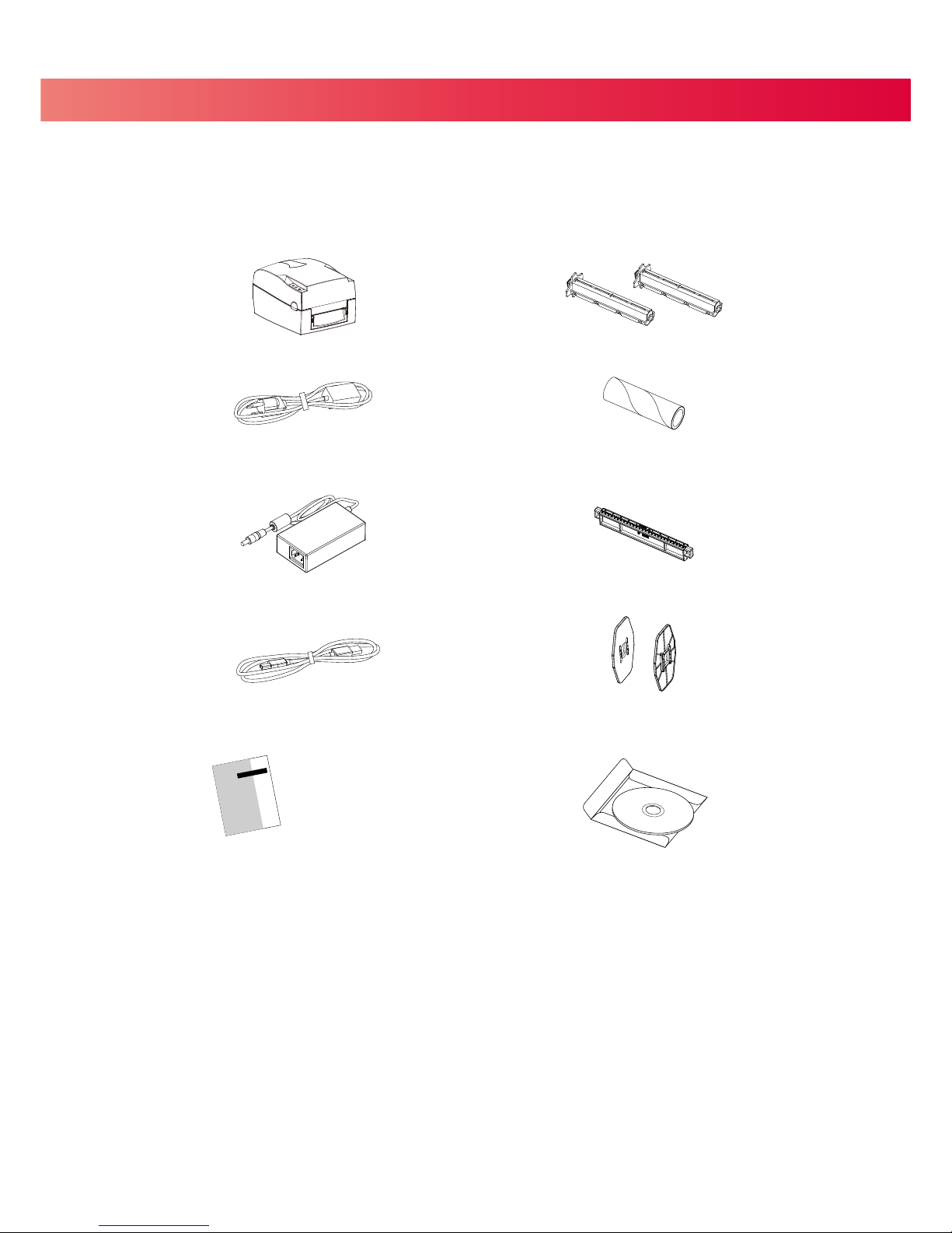
Please check that all of the following items are included with your printer.
=
V-425E / V-434E Printer
=
Power Cord
=
AC Adapter
=
USB Cable
=
Quick Start Guide
=
Ribbon Hubs ( 2 )
=
Empty Ribbon Core
=
Label Supply Hub
=
Label Guide Plates ( 2 )
=
CD ( EASYLABEL Start software and Users Manual )
Page 6
1 Barcode Printer
1.2 Getting To Know Your Printer
4
Overview
=
Front
=
Rear
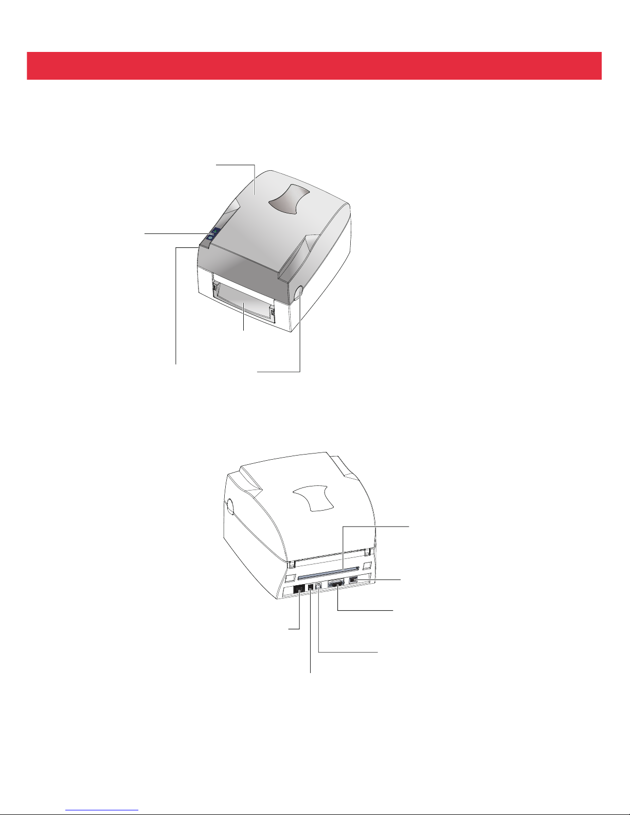
TOP COVER
COVER RELEASE BUTTONS
FRONT COVER
SERIAL PORT ( RS-232 )
POWER SWITCH
- ON
- OFF
FAN-FOLD LABEL SLOT
Feed slot for external label feeding
POWER JACK
USB PORT
2
OPERATION PANEL
ETHERNET PORT
Page 7
1 Barcode Printer
4
Open Cover
4 Open Print Mechanism
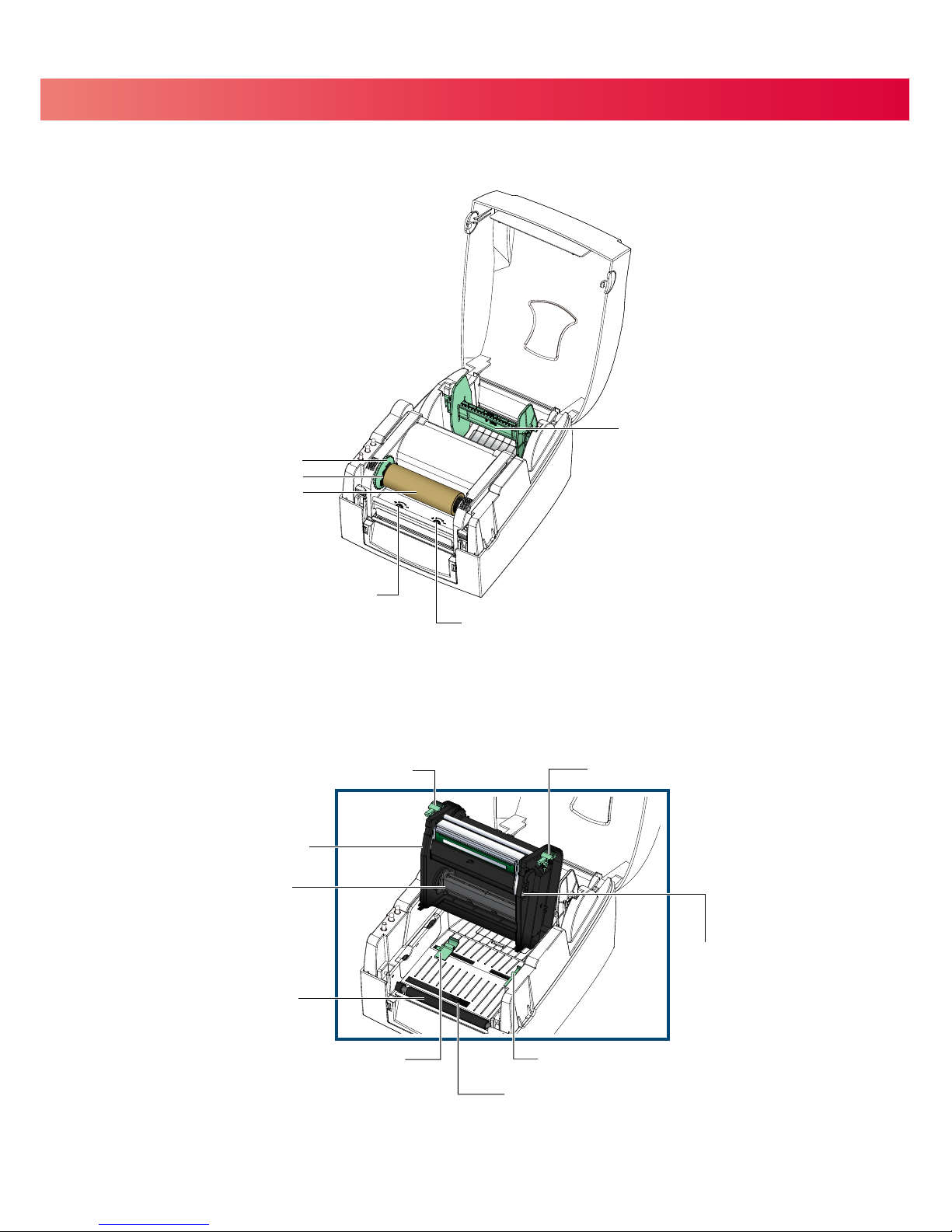
PRINTHEAD PRESSURE ADJUSTMENT SCREW ( LEFT )
PRINTHEAD PRESSURE ADJUSTMENT SCREW ( RIGHT )
LABEL SUPPLY MODULE
- LABEL SUPPLY HUB
- LABEL GUIDE PLATES ( 2 )
RIBBON MODULE
- RIBBON FEED MECHANISM
- RIBBON HUB
- EMPTY RIBBON CORE
LABEL GUIDE ( RIGHT )
RELEASE CATCH ( RIGHT )
RIBBON SUPPLY HUB
RELEASE CATCH ( LEFT )
LABEL GUIDE ( LEFT )
PRINT MECHANISM
PLATEN ROLLER
LABEL SENSOR
PRINT LINE ADJUSTMENT SCREW
3
Page 8
2 Printer Setup
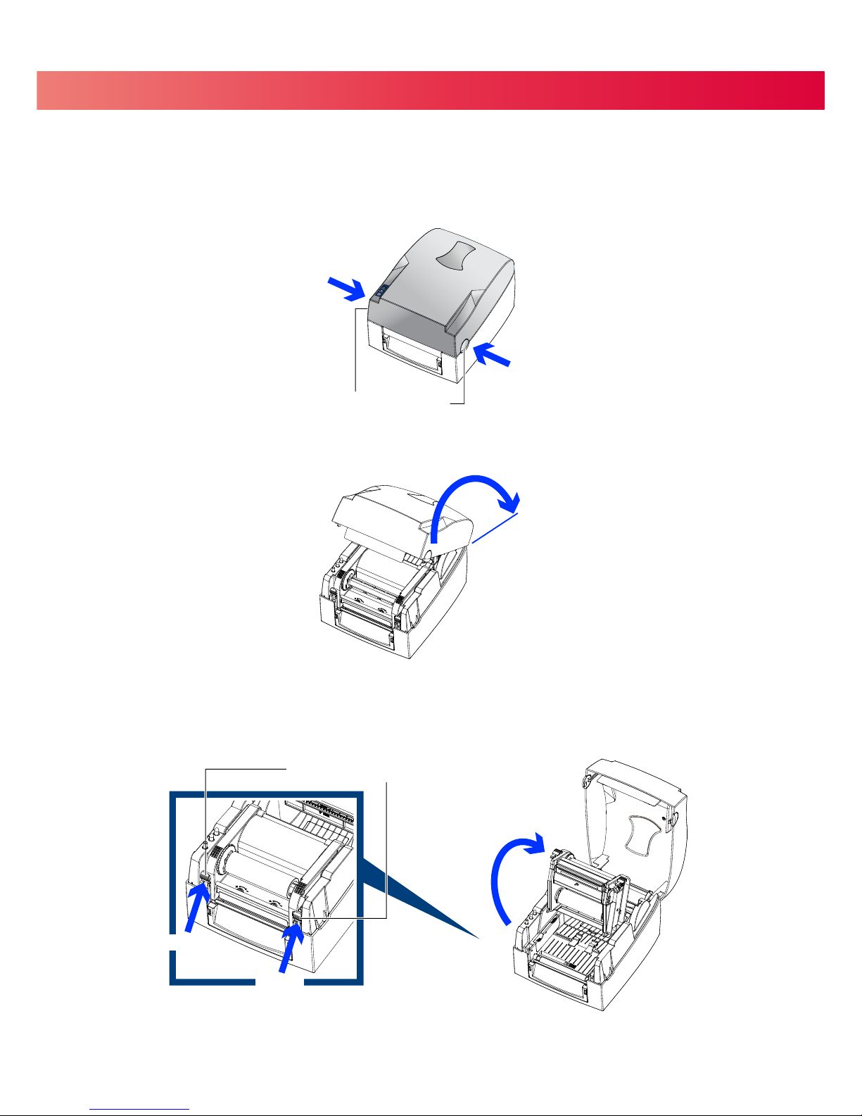
2.1 Opening the Top Cover
4
Open the Top Cover by pressing the release buttons on both sides of the
Top Cover and lift the cover.
2.2 Open the Print Mechanism
4 Open the print mechanism by pressing the Release Catches and then lift the Print Mechanism.
Press the button
COVER RELEASE BUTTONS
Press the button
Lift the printer cover
Lift the print mechanism
Press
Press
RELEASE CATCHES
4
Page 9
2 Printer Setup
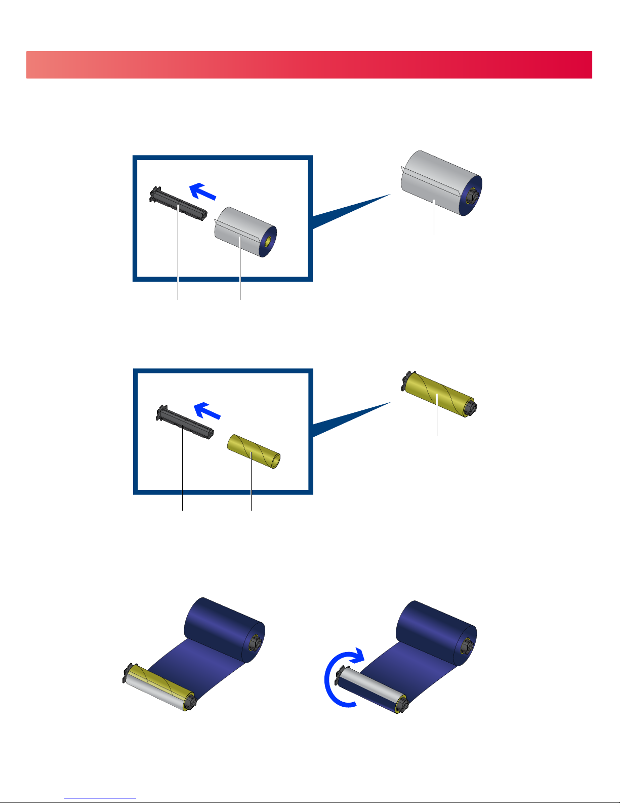
2.3 Loading Ribbon
4 Place the new ribbon on one of the Ribbon Hubs.
Place an empty ribbon core on the other Ribbon Hub.
Attach the ribbon to the empty ribbon core and wind the ribbon around the core 2~3 times.
RIBBON SUPPLY HUB
Place on the Hub
RIBBON HUB NEW RIBBON
Place on the Hub
EMPTY RIBBON CORERIBBON HUB
RIBBON REWIND HUB
5
Wind the ribbon around the core
Page 10
2 Printer Setup
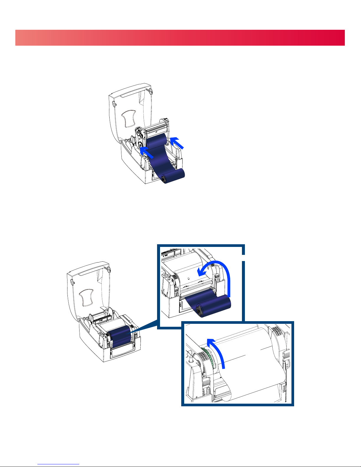
4 Place the Ribbon Supply Hub at the back of the Print Mechanism.
Pass the ribbon under the Print Head.
Insert the Ribbon Rewind Hub into the Print Mechanism.
Insert into the Print Mechanism
Wind up any slack
Insert into the Print Mechanism
6
Close the Print Mechanism.
Make sure that it clicks into place.
Wind up any slack in the ribbon.
Page 11
2 Printer Setup
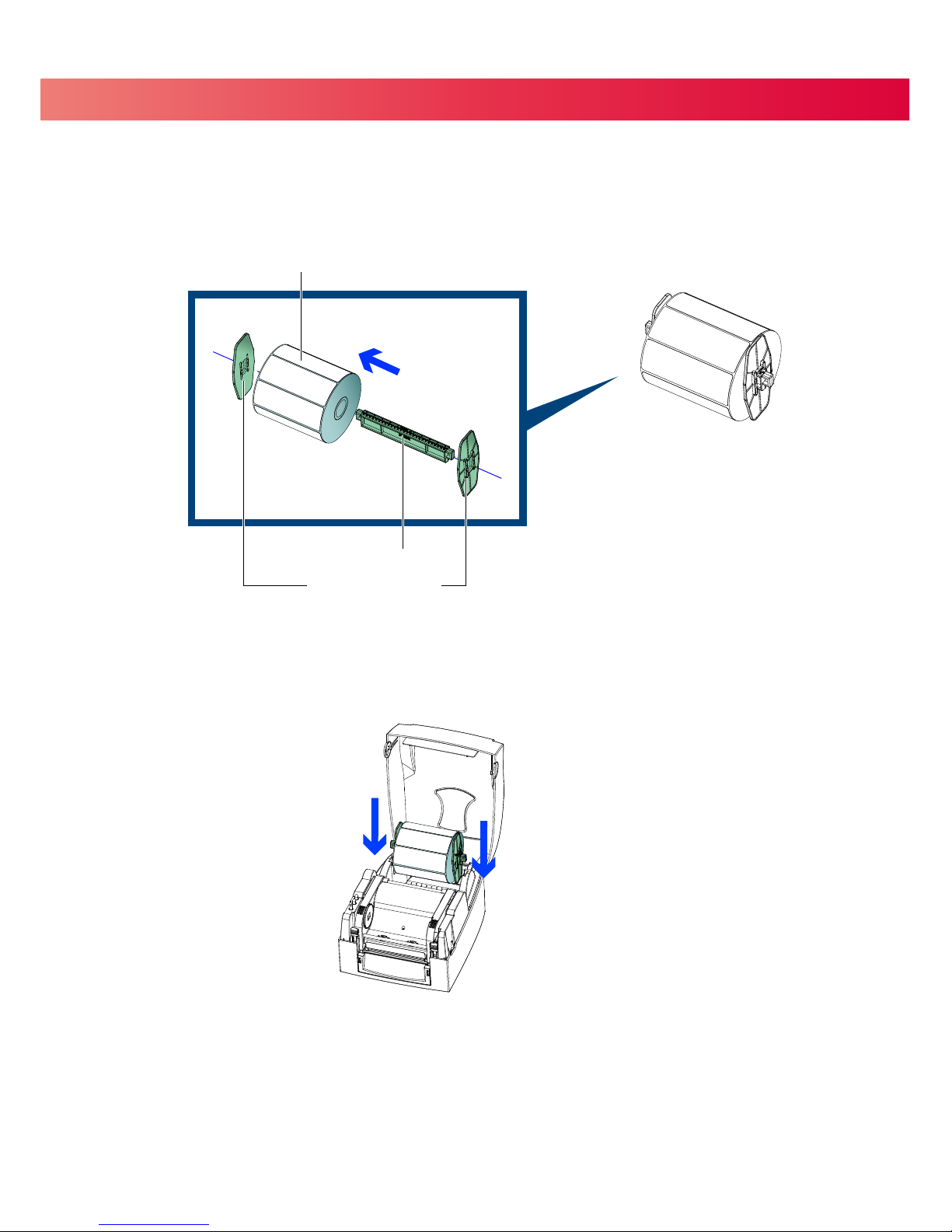
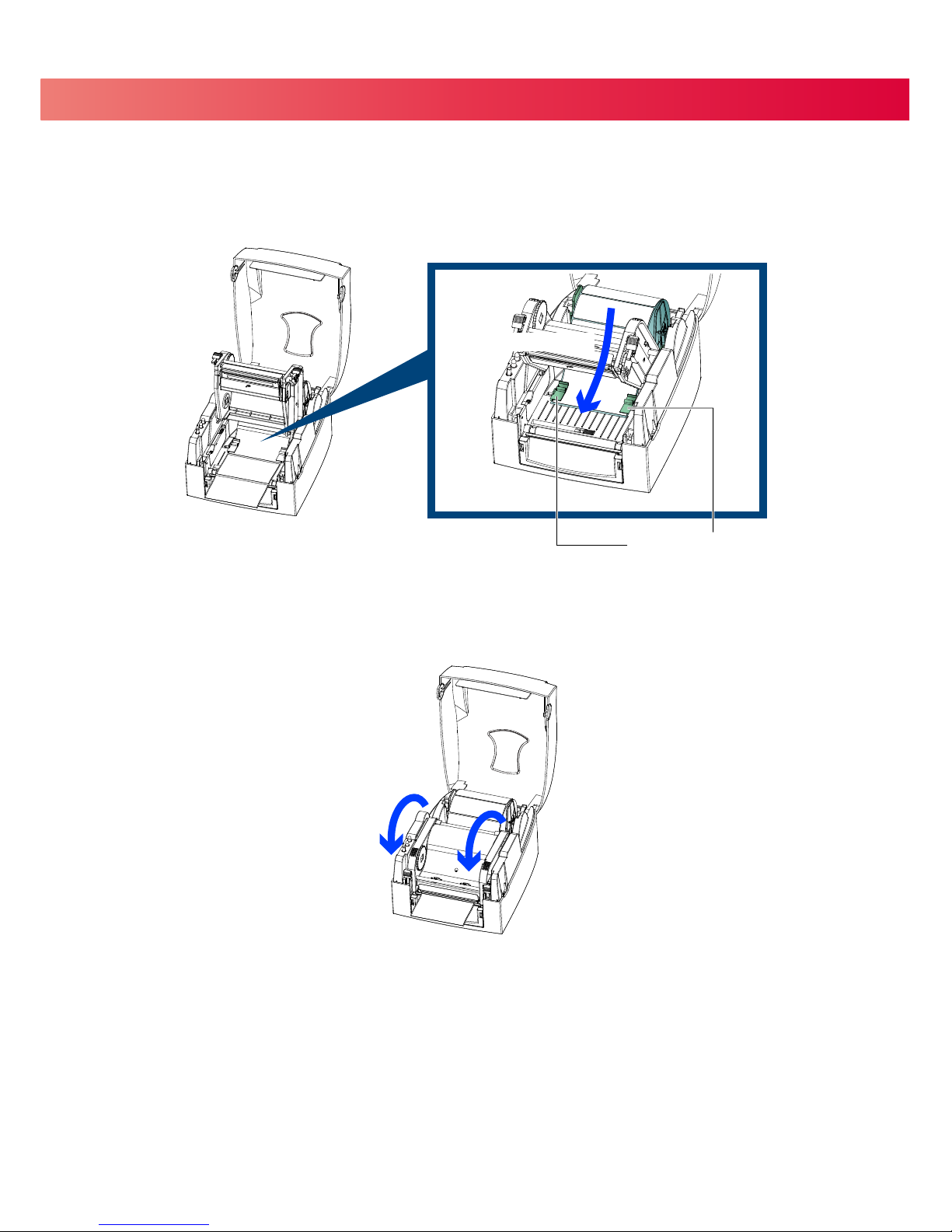
2.4 Loading Labels
4 Place a roll of label stock on the Label Supply Hub then slide a Label Guide Plate on to each side of the label roll.
4 Now load the label stock into the Printer.
Place on the Label Supply Hub
LABEL STOCK
LABEL SUPPLY HUB
LABEL GUIDE PLATES
Place in the Printer
7
Page 12
2 Printer Setup
Open the Print Mechanism.
Feed the labels through the Label Guides and up to the Tear-off Plate.
Adjust the Label Guides to the label width.
Close the Print Mechanism.
Through the Label Guides
LABEL GUIDES
8
Close
Page 13
2 Printer Setup
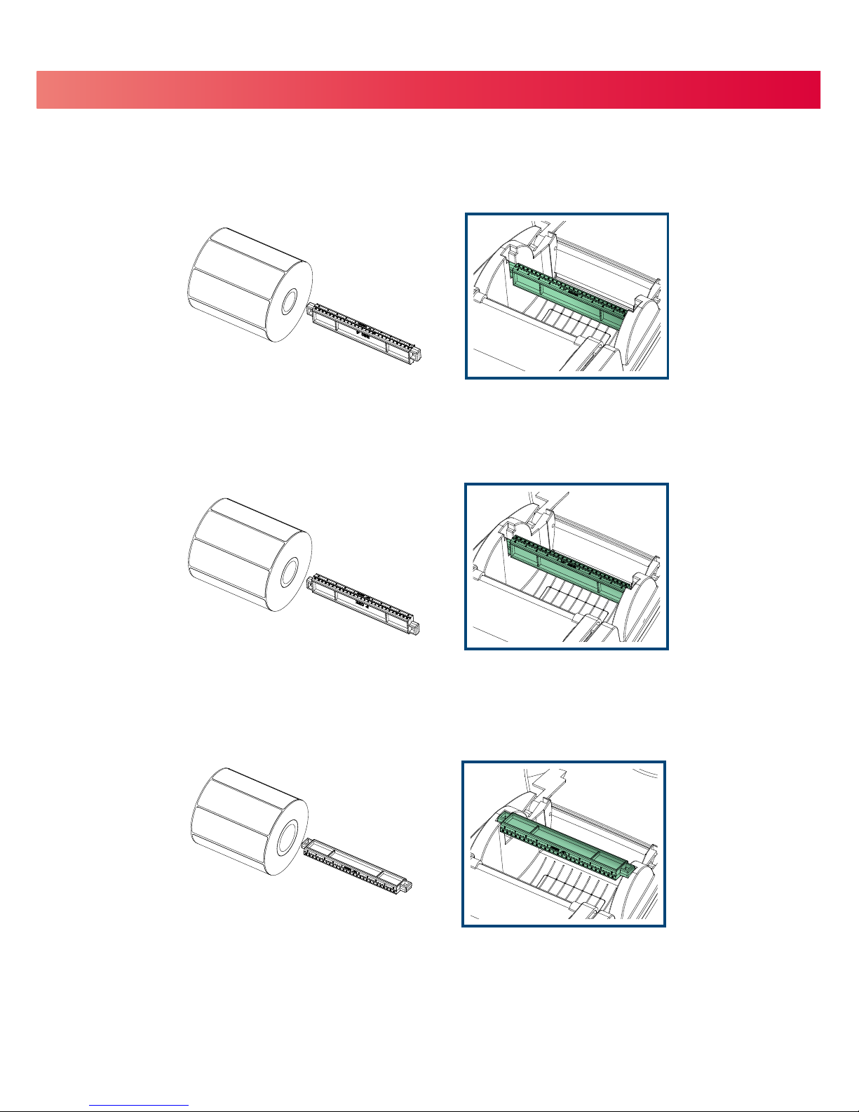
2.5 Label Supply Hub Installation
4 1" Cores
Installing the label supply hub for 1" cores.
4 1.5" Cores
Installing the label supply hub for 1.5" cores.
4 3" Cores
Installing the label supply hub for 3" cores.
9
Page 14
2 Printer Setup
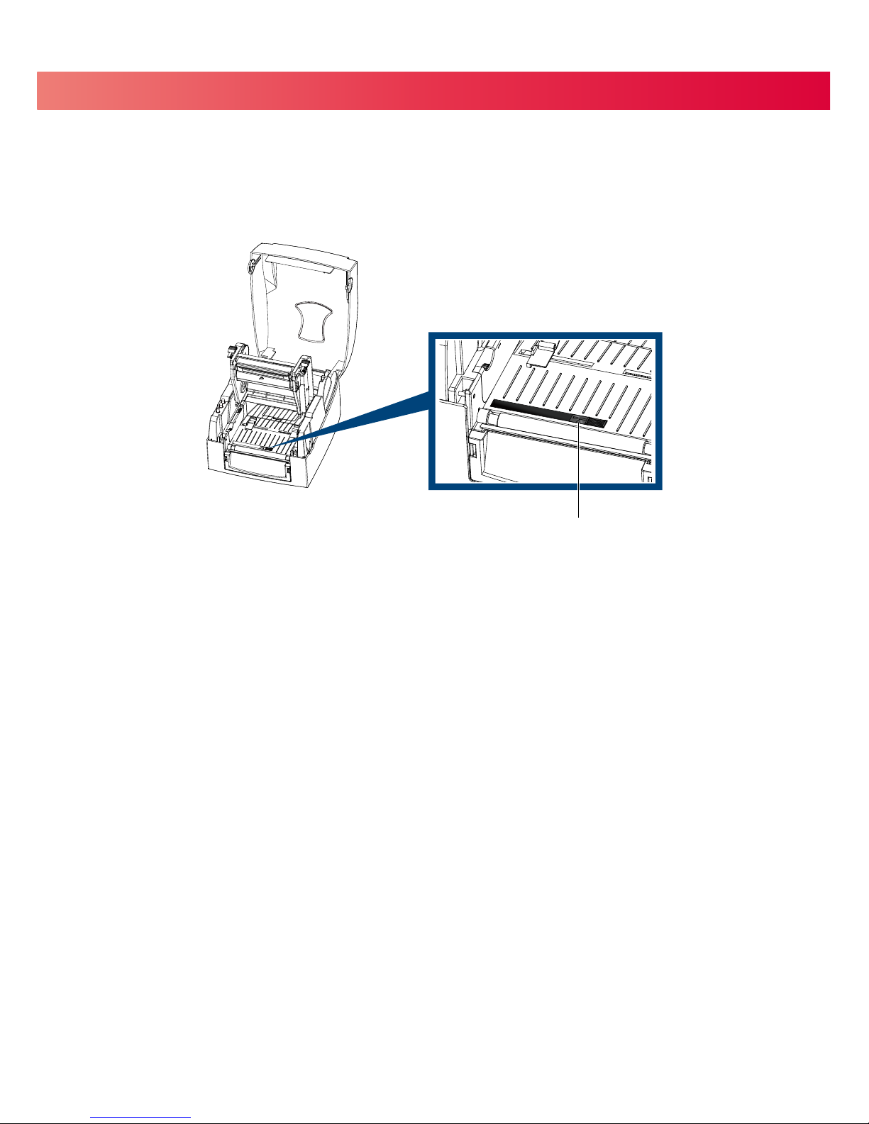
2.6 Preparation for Tag Printing
In tag printing, the tag hole indicates the height of a label.
Position the Sensor so that it is directly below the location of the tag hole.
The tag hole should be at least 3 mm in diameter.
SENSOR POSITION
10
Page 15
B1
B2
A1
A2
2 Printer Setup
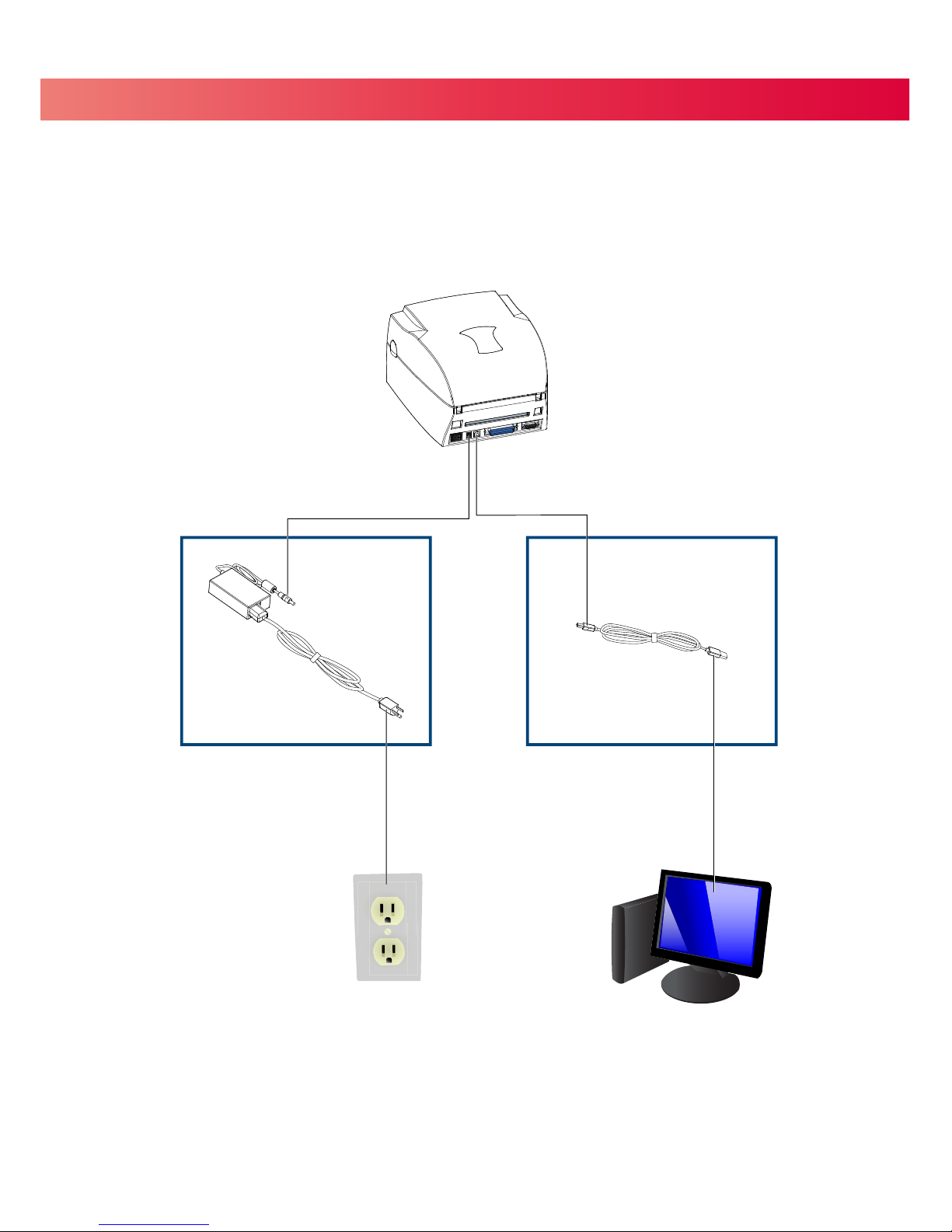
2.7 Connecting the Printer to Your Computer
B1
USB PORT
A1
POWER JACK
A2
ELECTRICAL OUTLET
B2
USB PORT
11
1. Ensure that the printer is turned off.
2. Connect the power cord to the AC adapter and connect the AC adapter to the printer.
3. Plug the power cord into an electrical outlet.
4. Connect the USB cable to the printer and your computer.
5. Turn the printer on. The LED should light up.
Page 16
2 Printer Setup
12
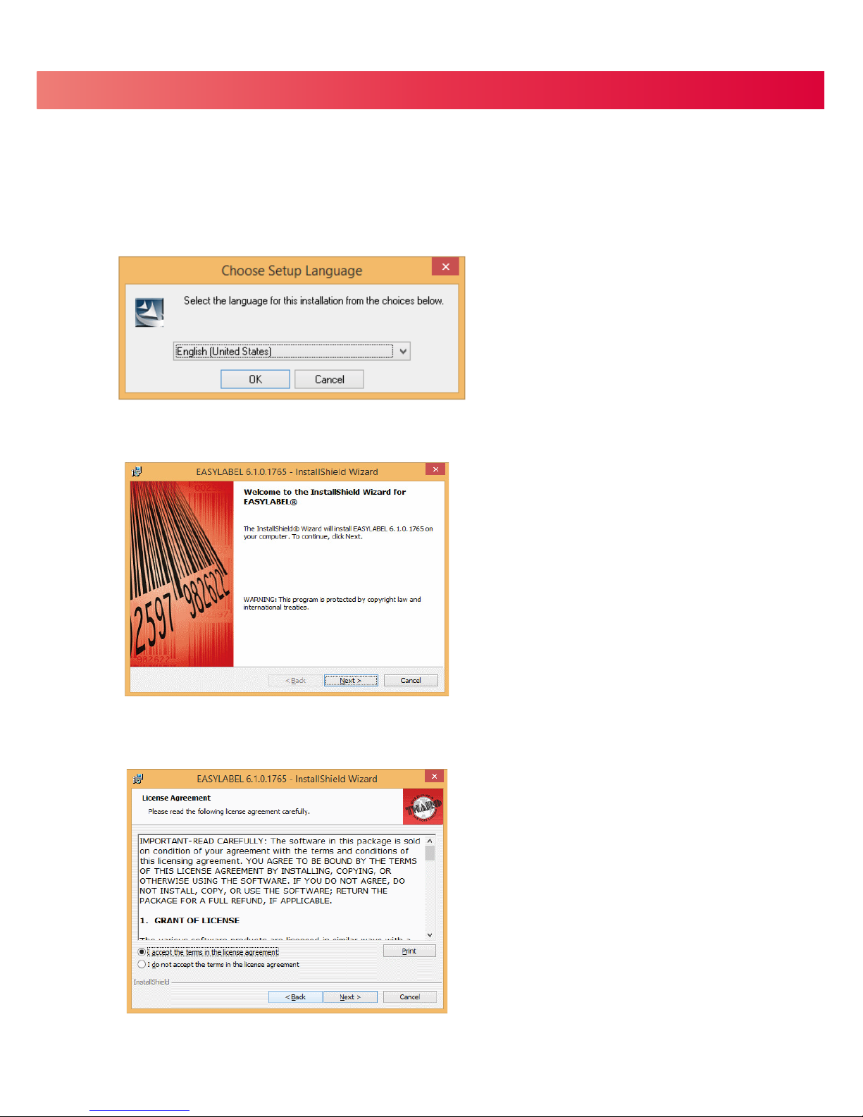
2.8 EASYLABEL Start Installation
2. The EASYLABEL InstallShield Wizard starts. Click “Next” to continue.
3. The next screen you can read EASYLABEL’s License Agreement. Click the “I accept the terms in the license agreement”
radio button and click “Next” to continue the installation.
1. Insert the product CD into CD/DVD drive of your computer. Open the "install” folder on the CD.
Right click on the setup.exe icon and choose “Run as Administrator” to start the installation.
Select a language for the installation and click OK to continue.
EASYLABEL Start is the free labeling package included with every Tharo printer.
Page 17
2 Printer Setup
13
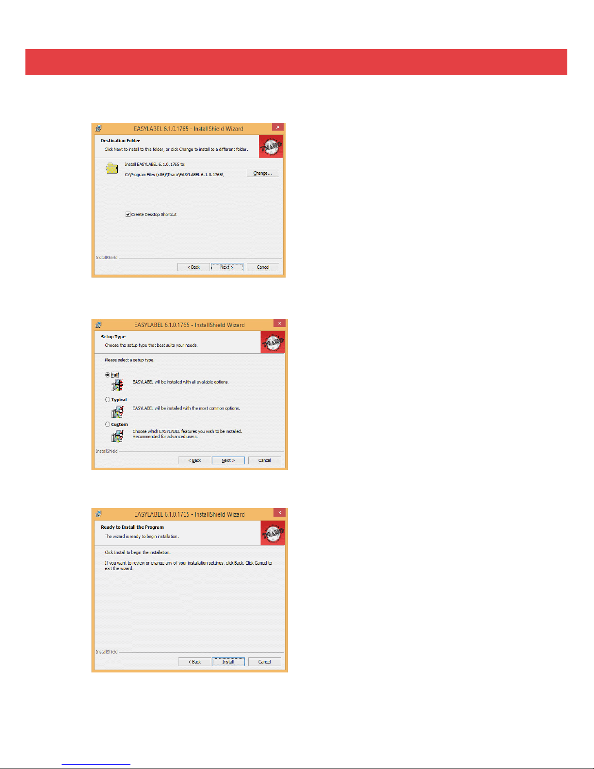
4. The next screen allows you to specify the directory to install EASYLABEL into. In most cases the default is fine.
You may also specify if you want an EASYLABEL icon on your desktop. Click on “Next” to continue.
5. The next step allows you to specify the installation type. “Full” is recommended for most users. Click “Next” to continue.
6. This is the confirmation screen. Click Install to install EASYLABEL Start.
Page 18
2 Printer Setup
14
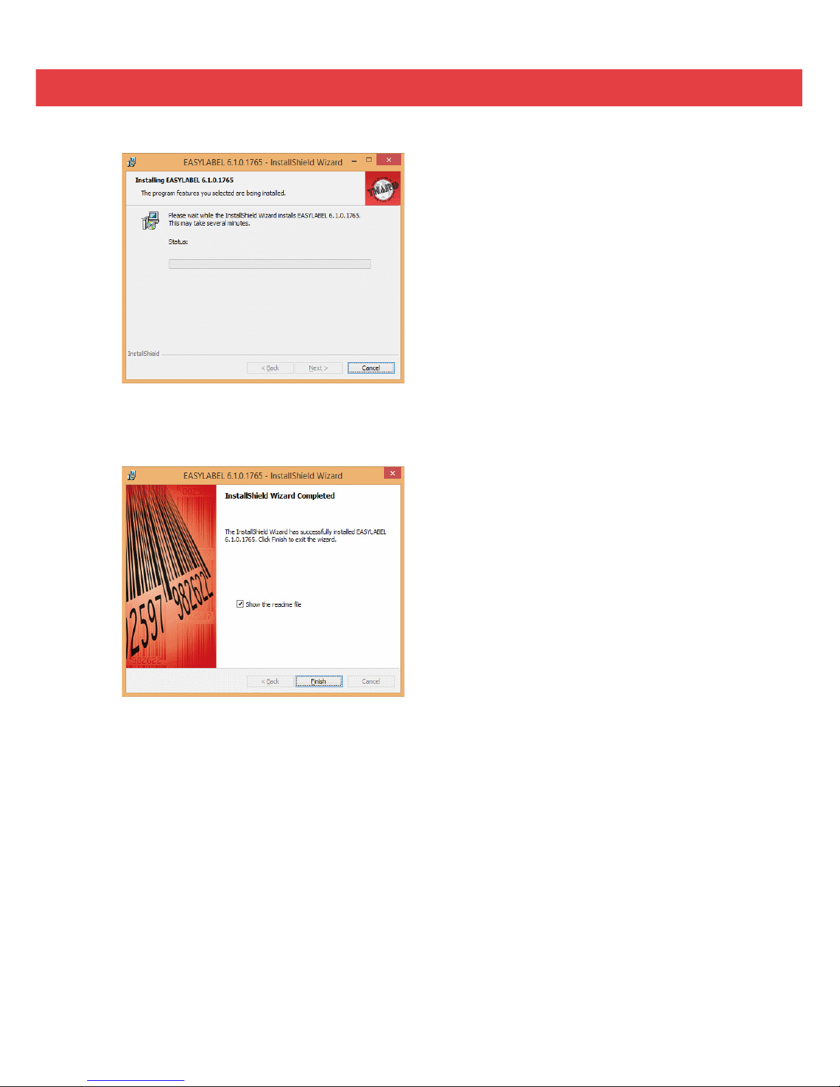
8. The installation is complete. Click “Finish” to close the InstallShield Wizard.
9. You are ready to start using EASYLABEL. If you are a new EASYLABEL user we recommend that you view the
EASYTutor tutorials. EASYTutor is the best way to get acquainted with your new labeling software. EASYTutor
can be found in the “EZtutor” folder on the product CD.
You may also view EASYTutor online at www.tharo.com/interactive.php
We suggest getting started with “Adding a USB printer” which is a great step-by-step walk through of how to
add a USB printer to EASYLABEL.
www.tharo.com/Interactive/adding_a_usb_printer/adding_a_usb_printer.htm
7. The Status screen will show the progress of the EASYLABEL Start installation.
Page 19

2 Printer Setup
15
Windows Drivers are NOT needed when printing to your Tharo Printer with EASYLABEL.
If you want to print to your Tharo Printer from other Windows applications then a Windows driver is needed.
STOP!
Do NOT plug the Printer's USB cable into your computer yet. There are some special installation steps for
Windows 8 and 10 users. If you are NOT using Windows 8 or 10 you can skip to the next page.
To install the Printer driver in Windows 8 or 10:
1. Open the "Tharo_Driver_Win8_Win10" folder.
2. Right Click on thr.inf and select "install"
3. Click on “Yes”
4. When the install finishes, Click on “OK”
5. Then plug the Printer's USB cable into your computer.
The printer should now be ready for use in Windows 8 or 10.
If you plugged in the printer without doing the above steps first, the printer is installed as an "Other Device"
and you will have to install the driver this way:
1. Open the Windows Control Panel
2. Click on "Hardware and Sound"
3. Under "Devices and Printers" heading click on "Device Manager"
4. Expand "Other Devices"
5. Right-click on the Tharo Printer and select "Update Driver Software"
6. Select "Browse my computer for driver software"
7. Click “Browse” and browse to where the "Tharo_Driver_Win8_Win10" folder and then click on “Next”
8. Click on “Install”
9. Click on “Close” to exit the wizard
The printer should now be ready for use in Windows 8 or 10.
Insert the product CD into CD/DVD drive of your computer.
2.9 Windows Driver Installation
Page 20
2 Printer Setup
16
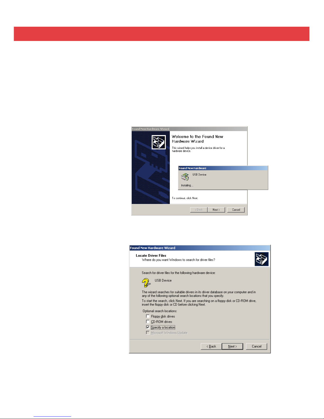
1. USB is a Plug & Play
facility. Once the USB
cable is connected
from PC to the printer,
the PC will
automatically detect
the new device and
begin the installation
process.
2. Select ‘Specify a
location’ and specify
the path of the printer
driver.
3. Follow the instructions
in the Wizard to
complete the
installation.
www.tharo.com
The printer can be installed on Windows releases other than Windows 8 or Windows 10 without any special
steps.
Insert the product CD into CD/DVD drive of your computer.
Turn the printer on and connect it to your computer with a USB cable.
The “Found New Hardware Wizard” should take over and install the drivers.
At some point you will be able to specify a location of the drivers.
Simply point the Wizard to the thr.inf file in the Windows Driver folder on the product CD.
Page 21
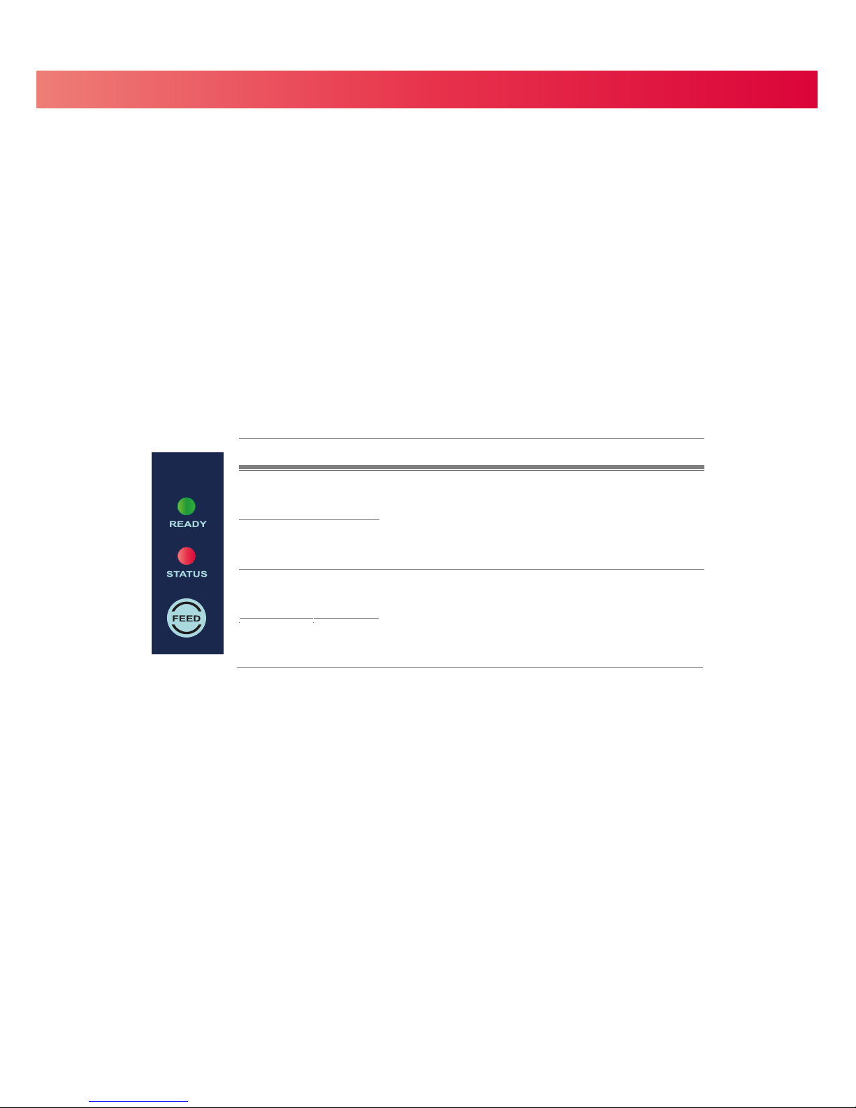
3 Operation Panel
3.1 Operation Panel
4 FEED Button
When you press the FEED button, the printer advances the label stock to a defined stop position.
If you are using continuous labels, pressing the FEED button will advance label stock until you release the button.
If you are using labels with gaps or black marks, pressing the FEED button will advance only one label.
If the label does not stop at the correct position the sensor must be calibrated. Follow the Label Calibration
instructions in section 3.2 of this manual
.
4 LED Indicators
17
LED indicator Status Description
Green
Standby mode
The printer is ready for operation.
READY
OFFSTATUS
OFFREADY
RedSTATUS
Error mode
There is an error.
(See Section 3-3. for a list of errors)
Beeps
2 x 2 beeps
2 x 3 beeps
2 x 4 beeps
Page 22

3 Operation Panel
3.2 Label Calibration and Self-Test
The printer can automatically detect and store label height.
That means the host computer does not need to transmit the label height to the printer.
The Self-Test function lets you check whether the printer is functioning normally.
Follow these steps to run the Label Calibration and Self-Test.
STEP-014Check that the label stock is loaded correctly.
STEP-024Turn the Printer off and press the FEED button.
STEP-034Turn the Printer on, keeping the FEED button pressed. When the READY LED starts to flash
red and the STATUS LED lights up orange, release the FEED button. The printer will now perform
a Label Calibration.
STEP-044Once the Label Calibration is complete, the Printer will print a Self-Test label.
V-425E GX.XXX
USB S/N: XXXXXXXX
Serial port : 96,N,8,1
MAC Addr: xx-xx-xx-xx-xx-xx
DHCP Enable
IP xxx.xxx.xxx.xxx
Gateway xxx.xxx.xxx.xxx
Sub-Mask xxx.xxx.xxx.xxx
###############################
1 DRAM installed
Image buffer size : 1500 KB
000 FORM(S) IN MEMORY
000 GRAPHIC(S) IN MEMORY
000 FONT(S) IN MEMORY
000 ASIAN FONT(S) IN MEMORY
000 DATABASE(S) IN MEMORY
000 TTF(S) IN MEMORY
2048 KB FREE MEMORY
^S4 ^H10 ^R000 ~R200
^W108 ^Q100,0,0 ^E12
Option : ^D0 ^O0 ^AD
Reflective AD : 1.80 2.01 1.89 [0.21_0]
Code Page : 850
Default state= No
Model & Version
USB ID setting
Serial port setting
MAC address of Ethernet port
IP protocol setting
IP address of Ethernet port
Gateway setting
Netmask setting
Number of DRAM installed
Image buffer size
Number of forms
Number of graphics
Number of fonts
Number of Asian fonts
Number of Databases
Number of Scalable fonts
Free memory size
Speed, Density, Ref. Point, Print direction
Label width, Form length, Stop position
Cutter, Label Dispenser, Mode
Sensor Setting
Code Page
Printer is on factory defaults
18
The contents of a sample Self-Test printout can be seen below.
Page 23
3 Operator Panel
3.3 Error Alerts
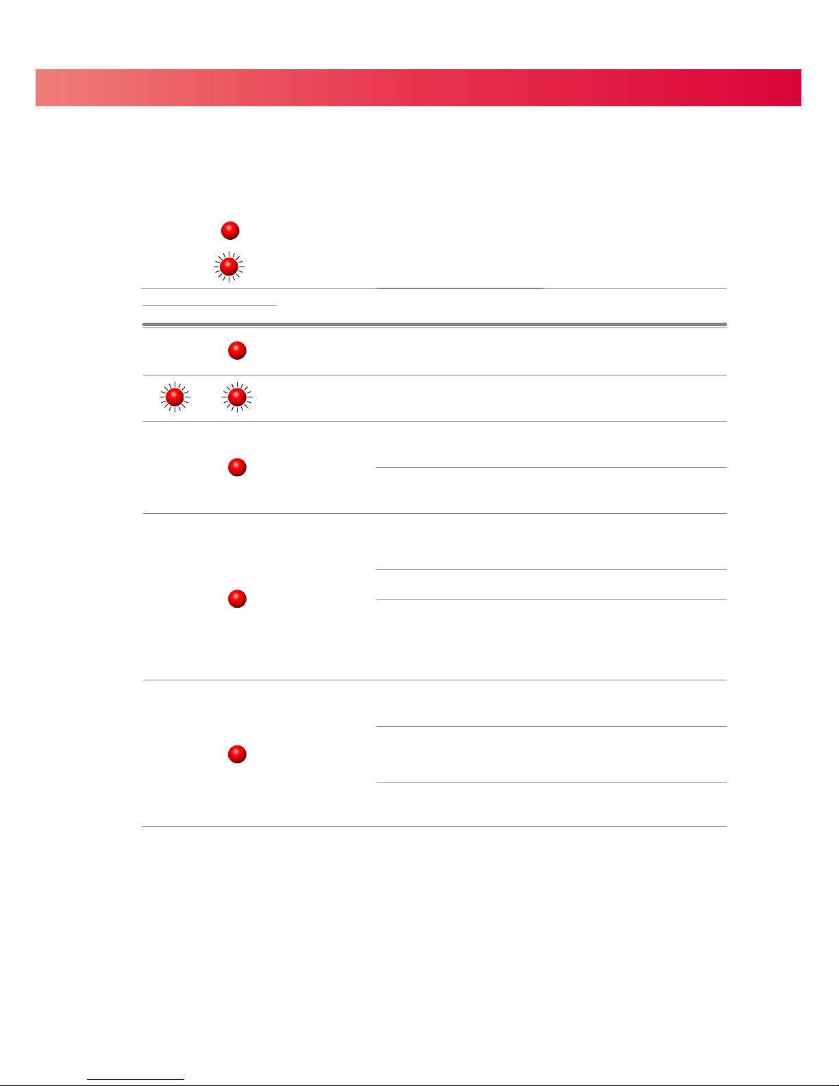
In the event of a problem that prevents normal functioning of the printer, you will see an error message on LED
indicators and hear some beep signals. Please refer to below table for the error alerts.
19
=
Flashing
=
Light on
LED indicator
Beeps Description Solution
READY STATUS
2 x 4 beeps
The Print Mechanism is not
firmly closed.
Open the Print Mechanism and close
it again.
Print Head temperature is too high
Once the Print Head has cooled down,
the printer switches to standby mode.
2 x 3 beeps
No ribbon is installed and the
printer shows an error message.
Make sure that the printer is set to
direct thermal printing mode.
The ribbon is used up or the
Ribbon Supply Hub is not moving.
Replace the ribbon roll.
No label stock is detected.
Make sure that the label sensor is
positioned correctly. If the sensor still
does not detect the labels, run the
Label calibration function again.
The label stock is used up. Replace the label roll.
Improper feeding of labels.
Possible causes:
Media falling into the gap behind
the Platen Roller; the sensor cannot
detect a gap or black mark between the
labels; there are no labels loaded.
The memory is full. The printer
prints the message "File System
Full".
Delete unnecessary data from the
memory.
Unable to find file. The printer
prints the message "File Name
Not found".
Use the "~X4" command to print all
files. Then check whether the files
exist and whether the names are
correct.
A file of the same name already
exists. The printer prints the
message "Duplicate Name".
Change the name of the file and try
to download it again.
None
2 x 2 beeps
2 x 2 beeps
Page 24
4 NetSetting for Ethernet
20
4.1 Installing the NetSetting software
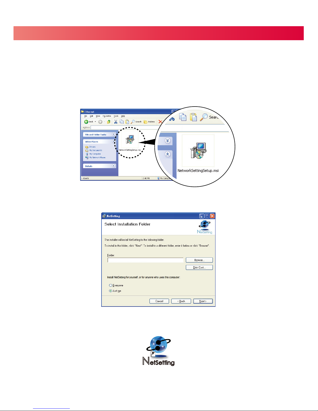
The NetSetting software is used to manage the network configuration of the Ethernet port.
NetSetting is available on the CD that ships with the printer or it can be downloaded from our website (www.tharo.com).
To install NetSetting:
5. Click ”Next” to continue the installation.
6. Once the installation has completed, you will see the NetSetting icon on your desktop.
1. Insert the Printer CD in your computer’s CD/DVD drive. Browse the contents of the CD and open the "Ethernet" folder.
2. Doubleclick on the NetworkSettingSetup.msi icon to start the installation.
3. The Setup Wizard will guide you through the installation procedure. Follow the instructions on the screen.
4. Specify an “Installation Folder".
D:\Ethernet
C:\Program Files\Tharo\NetSetting\
Page 25
4 NetSetting for Ethernet
21
4.2 NetSetting Interface
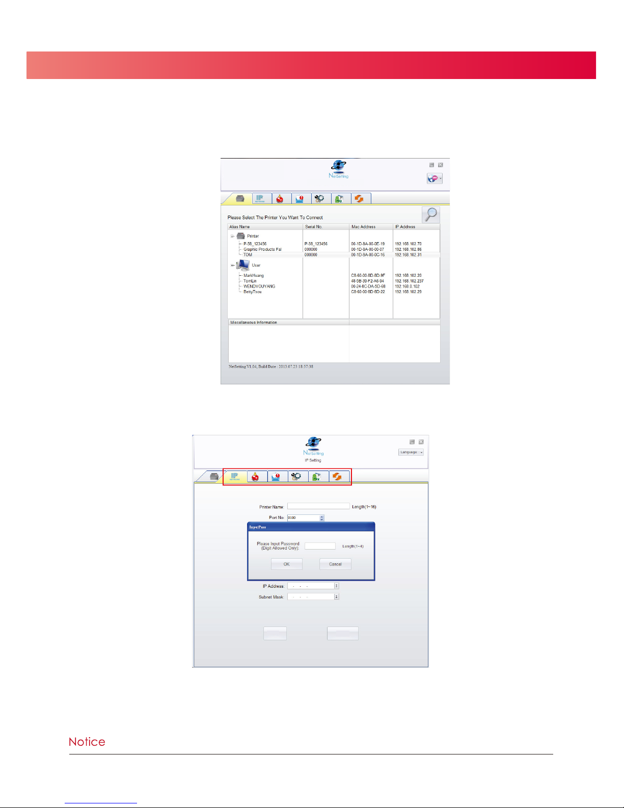
Doubleclick on the NetSetting icon to start the program.
You will see the start page below. The start page will display the basic information of any connected printer and your PC.
There are six tabs on the top of interface which are used to access different network configuration settings.
You will need to enter a password to enter the configuration pages.
Click on the magnifying glass icon to search your network for Tharo Ethernet printers.
Any printers that are detected are listed on the start page.
**** The default password is “1111”. You can change the password on the “IP Settings” tab.
ZX1200
Set
Refresh
Page 26
4 NetSetting for Ethernet
22
**** To fully benefit from the NetSetting software, you should be familiar with basic networking principles.
Please contact your network administrator for the required related network settings.
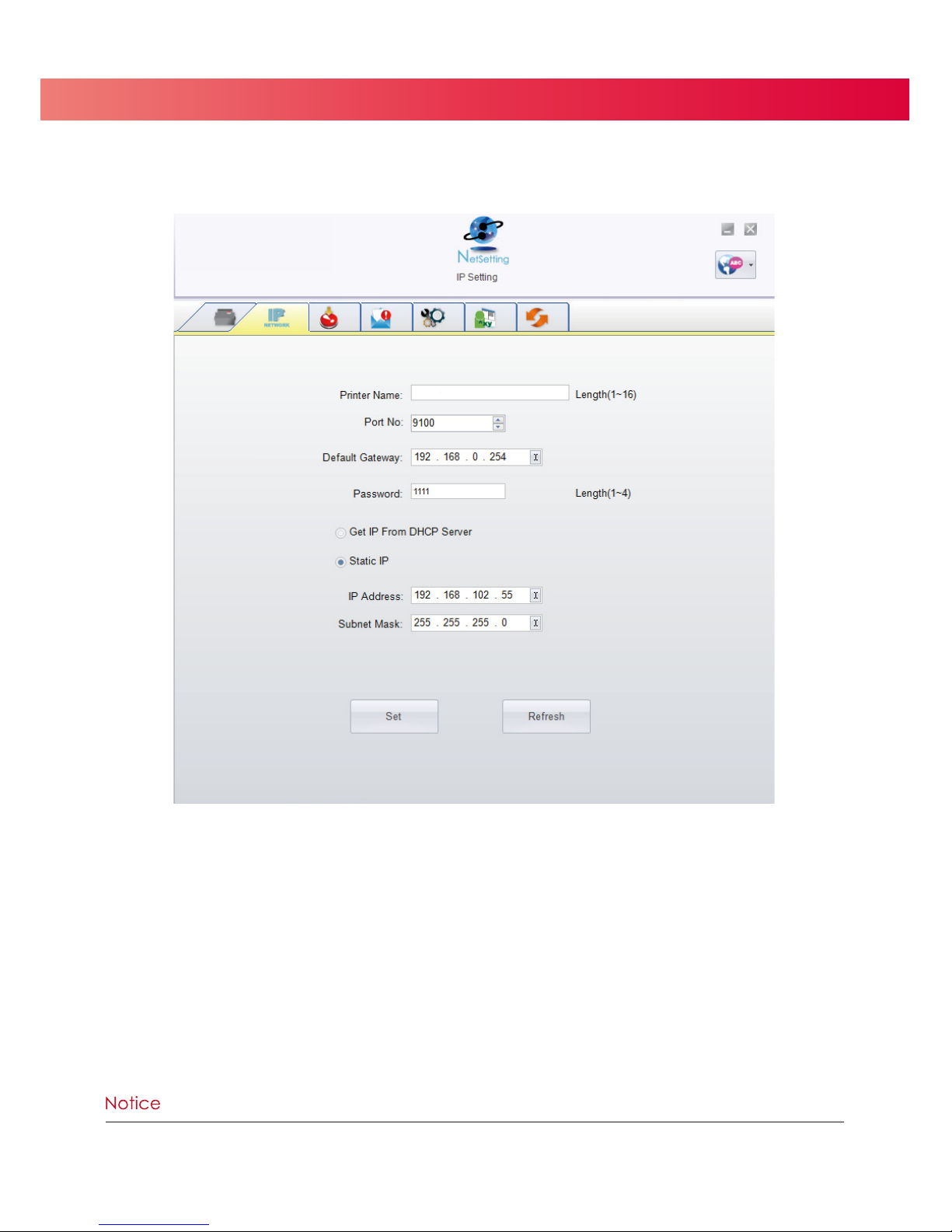
Click the “Set” button to apply the settings and the “Refresh” button to re-query the printer and refresh the values.
IP Settings
On the IP Settings tab you can change the Printer Name, Port Number, Default Gateway and Password.
You can also set the printer’s IP address ether by DHCP or by Static IP.
Page 27
4 NetSetting for Ethernet
23
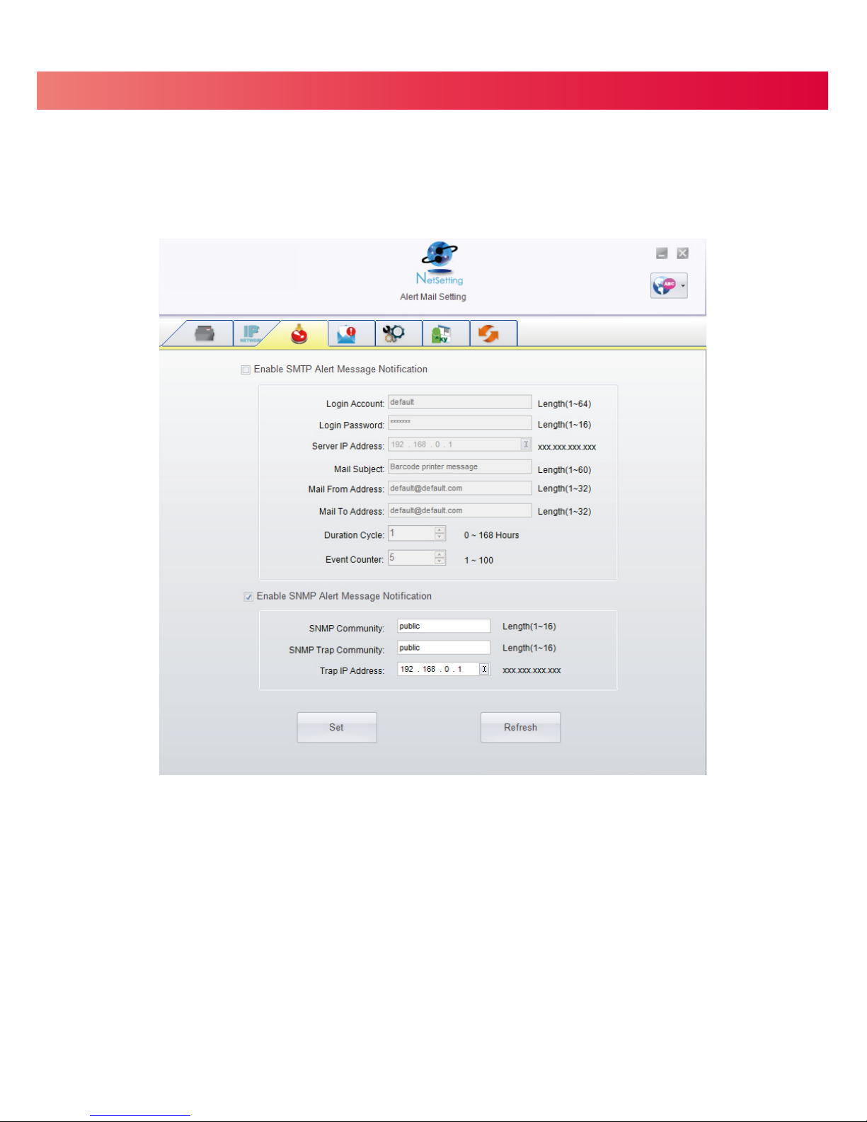
Click the “Set” button to apply the settings and the “Refresh” button to re-query the printer and refresh the values.
Alert Mail Setting
The Printer can send the alert messages to a designated mail account when errors occur. The alert
messages are sent by SMTP (Simple Mail Transfer Protocol) or SNMP (Simple Network Management Protocol).
You can set or change the configurations of SMTP and SNMP on the “Alert Mail Setting” tab.
Page 28
4 NetSetting for Ethernet
24
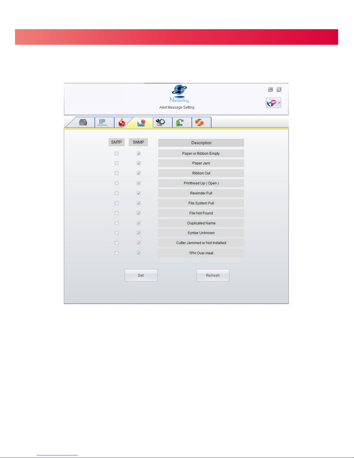
Alert Message Setting
Here you can specify which errors should trigger sending an email. The alert messages can be sent by SMTP, SNMP or both.
Click the “Set” button to apply the settings and the “Refresh” button to re-query the printer and refresh the values.
Page 29
4 NetSetting for Ethernet
25
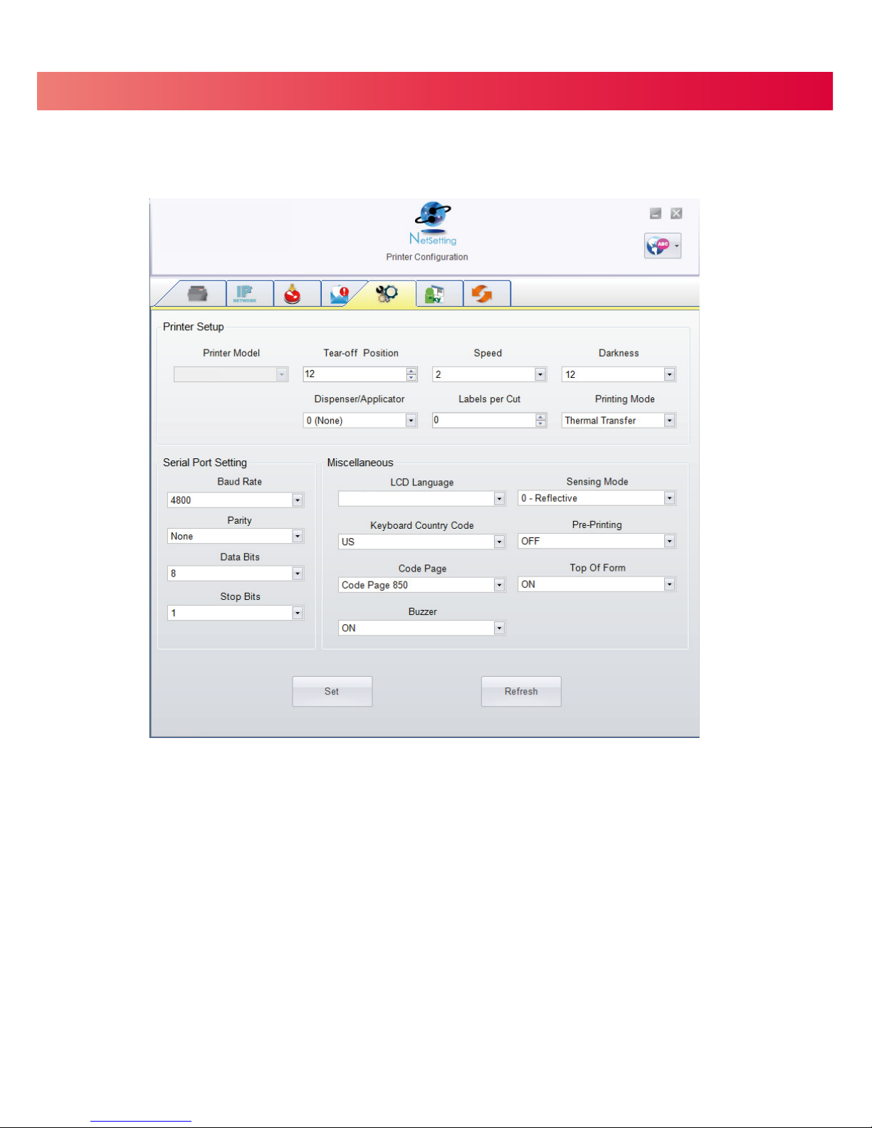
Printer Configuration
This tab allows you to change the configuration of the connected printer. Many of the printer settings can be modified on this setting page.
ZX1200i
Click the “Set” button to apply the settings and the “Refresh” button to re-query the printer and refresh the values.
English
T-4210
Page 30
4 NetSetting for Ethernet
26
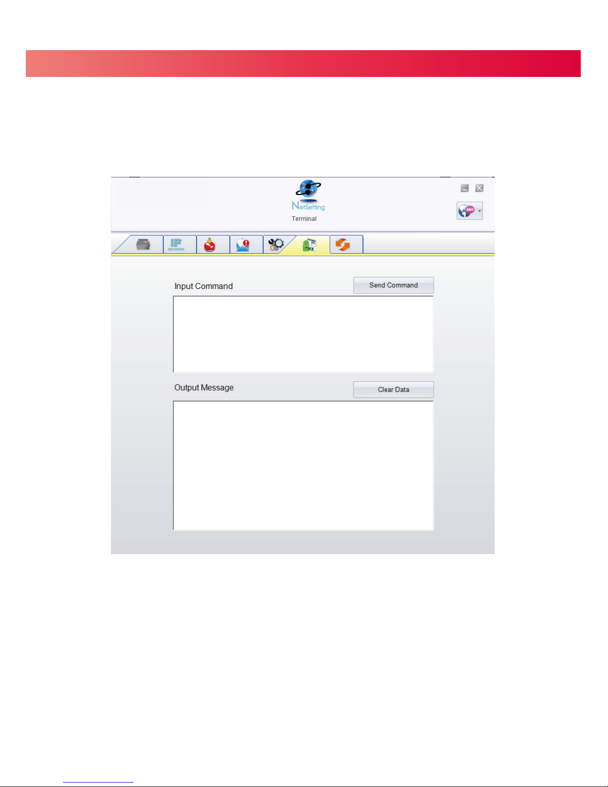
Terminal
The “Terminal” tab provides a communication interface for operator to control the printer. Enter printer
commands into the "Input Command" window and press the “Send Command” button, the commands
will be sent to the printer.
For the commands that return a response message, the message will be displayed in "Output Message" window.
Click on the “Clear Data” button to clear these messages.
Page 31
4 NetSetting for Ethernet
27
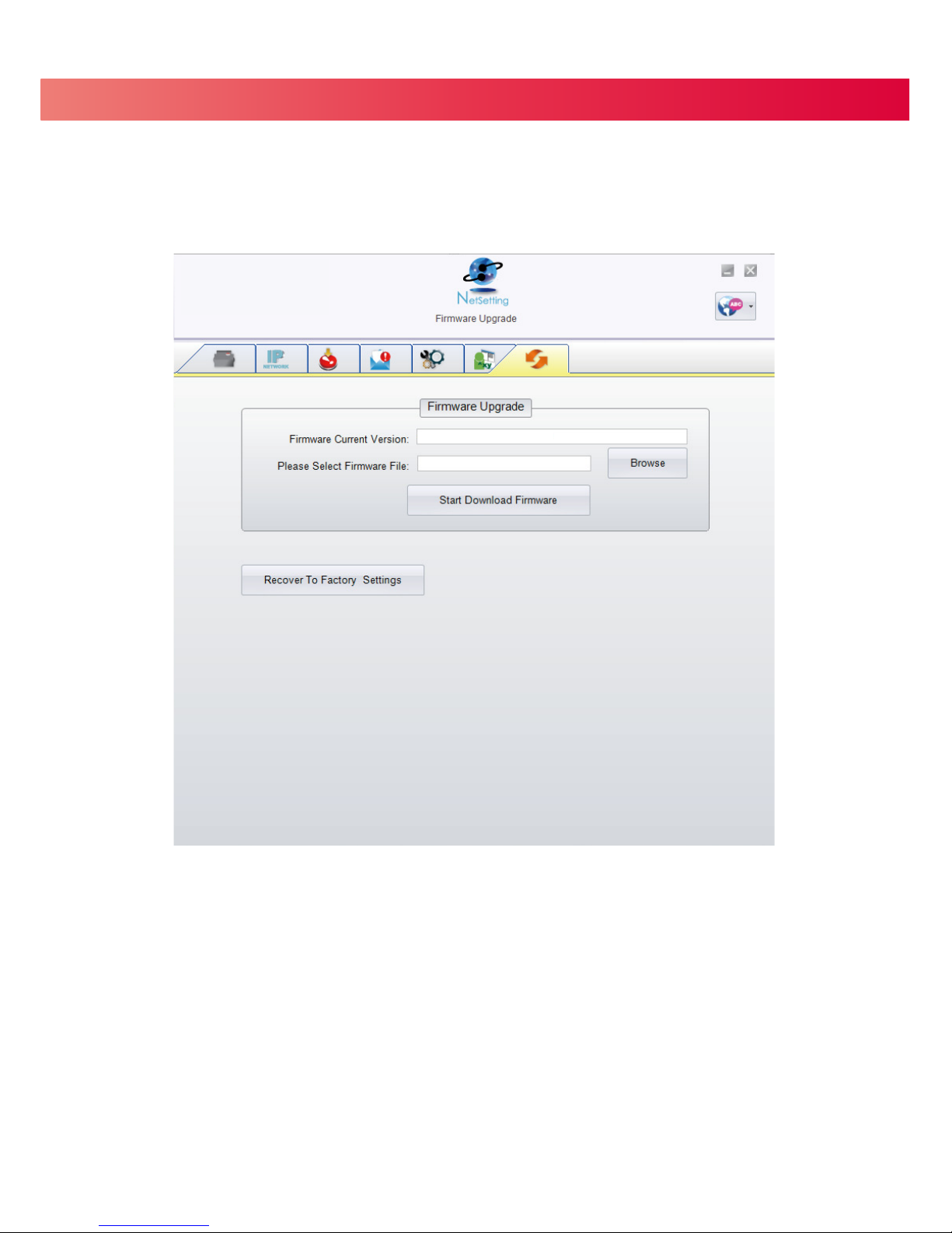
In addition to the firmware update, you can click the “Recover To Factory Settings” button to restore all of the printer
configuration settings back to factory default.
Firmware Upgrade
The current printer firmware version is shown on the “Firmware Upgrade” tab. You may also upgrade the printer firmware.
on this screen. Simply click the “browse” button and specify the firmware file location.
Then click the “Start Download Firmware” button. The printer firmware will be updated remotely.
BOOT : 1.000a1 F/W : ZX1200i 1.000a
Page 32
5 Accessories
5.1 Preparation
Please do the following before installing any of the optional modules.
Turn Off The Printer:
Turn off the printer before installing any module.
Open The Top Cover:
Open the Top Cover by pressing the release buttons on both sides of the Top Cover.
Please see the Section 2.1 of this manual for further information about opening the Top Cover.
Open The Print Mechanism:
Press the release catches on both sides of the Print Mechanism to open and lift the print mechanism.
Please see the Section 2.2 of this manual for further information about opening the Print Mechanism.
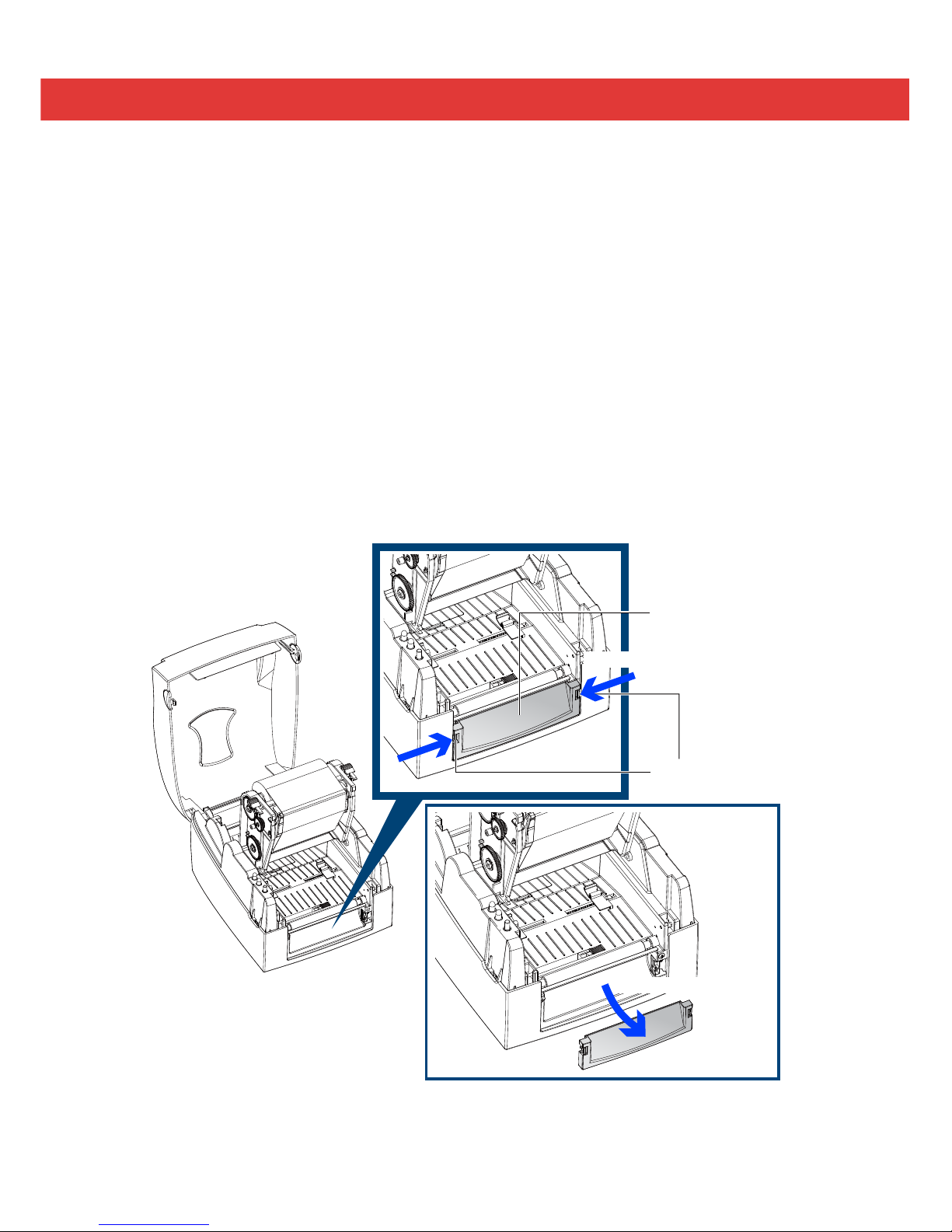
Remove the Front Cover:
Press in the two release tabs on the Front Cover.
Remove the Front Cover as shown in the illustration.
28
Remove the Front Cover
FRONT COVER
RELEASE TABS
Press the release tabs
Page 33
5 Accessories
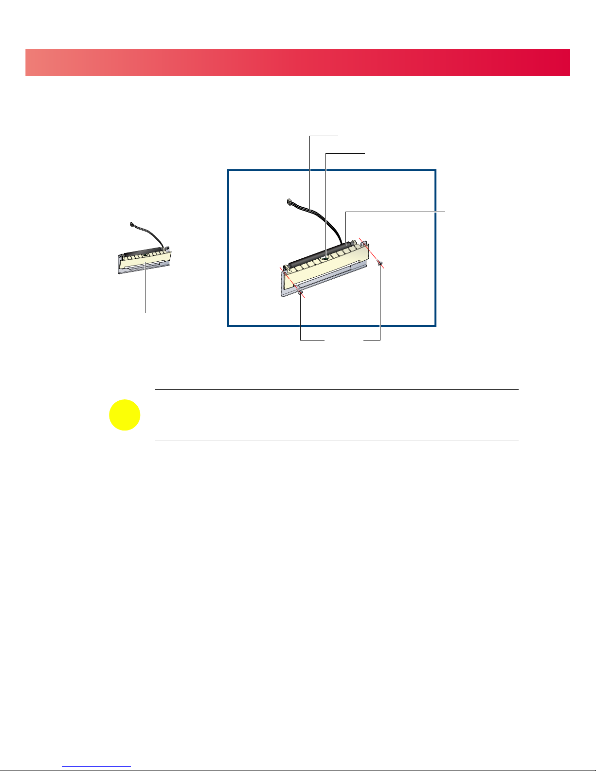
5.2 Installing the Label Dispenser
Please complete the preparation steps on page 28 before installing the Label Dispenser.
29
SCREWS
CONNECTION CABLE
SENSOR
PAPER FEED
ROLLER
LABEL DISPENSER MODULE
= Recommended label liner
thickness: 0.006 mm ± 10% and a weight of 65 g/m2 ± 6%
=
The maximum width when using the Label Dispenser is 110 mm.
= Set the Stop Position to 9mm when using the Label Dispenser
.
NOTICE
Page 34
5 Accessories
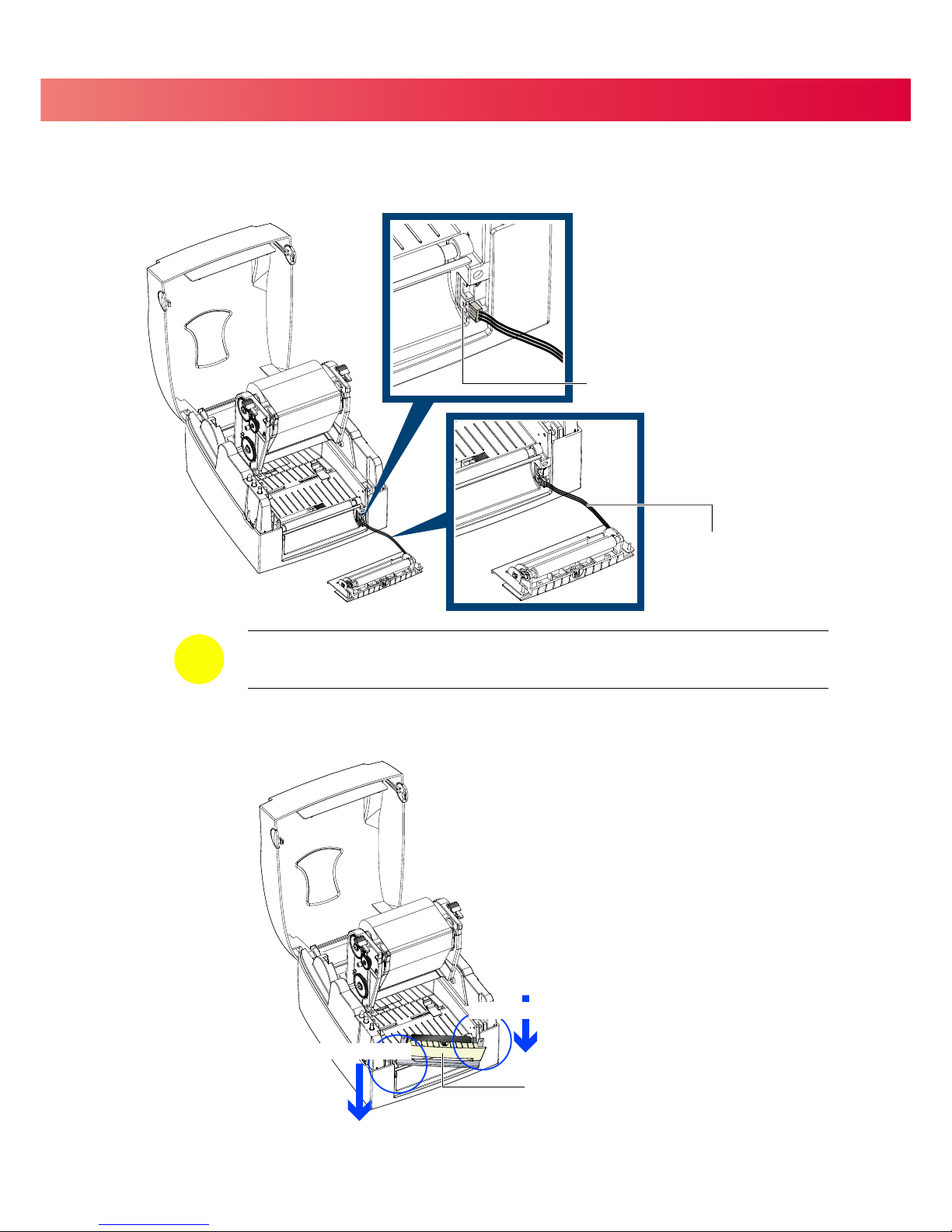
Connect the Connection Cable on the Label Dispenser to the lower jack on the front of the printer as shown below.
Install the Label Dispenser by pressing down on the right-hand side first and then the left-hand side.
30
RIGHT-HAND SIDE
LEFT-HAND SIDE
LABEL DISPENSER MODULE
=
The printer MUST be turned OFF or the motherboard may be damaged!
=
There are 2 jacks: the lower jack is for the Label Dispenser, the upper jack is for the Cutter.
NOTICE
LOWER JACK
CONNECTION CABLE
Page 35
5 Accessories
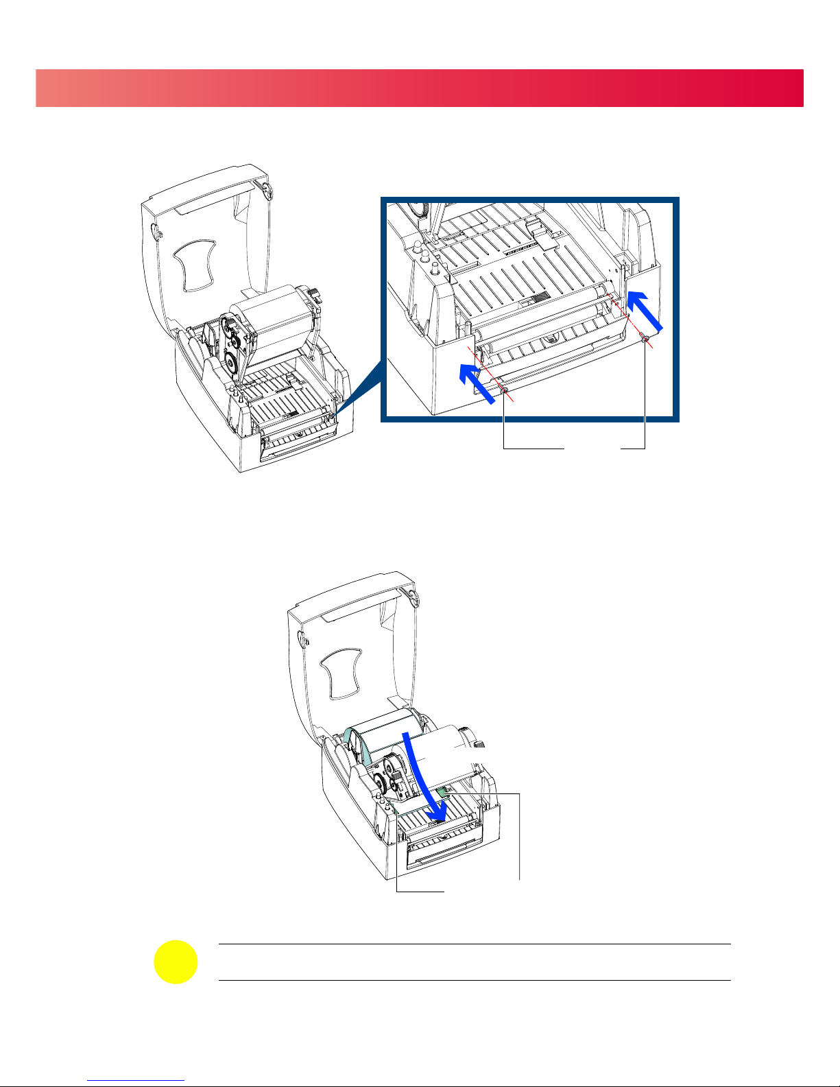
Secure the Label Dispenser using the screws provided.
Feed the labels through the Label Guides.
31
SCREWS
Through the Label Guides
LABEL GUIDES
=
Labels should be at least 25 mm high when using the Label Dispenser.
NOTICE
Page 36
5 Accessories
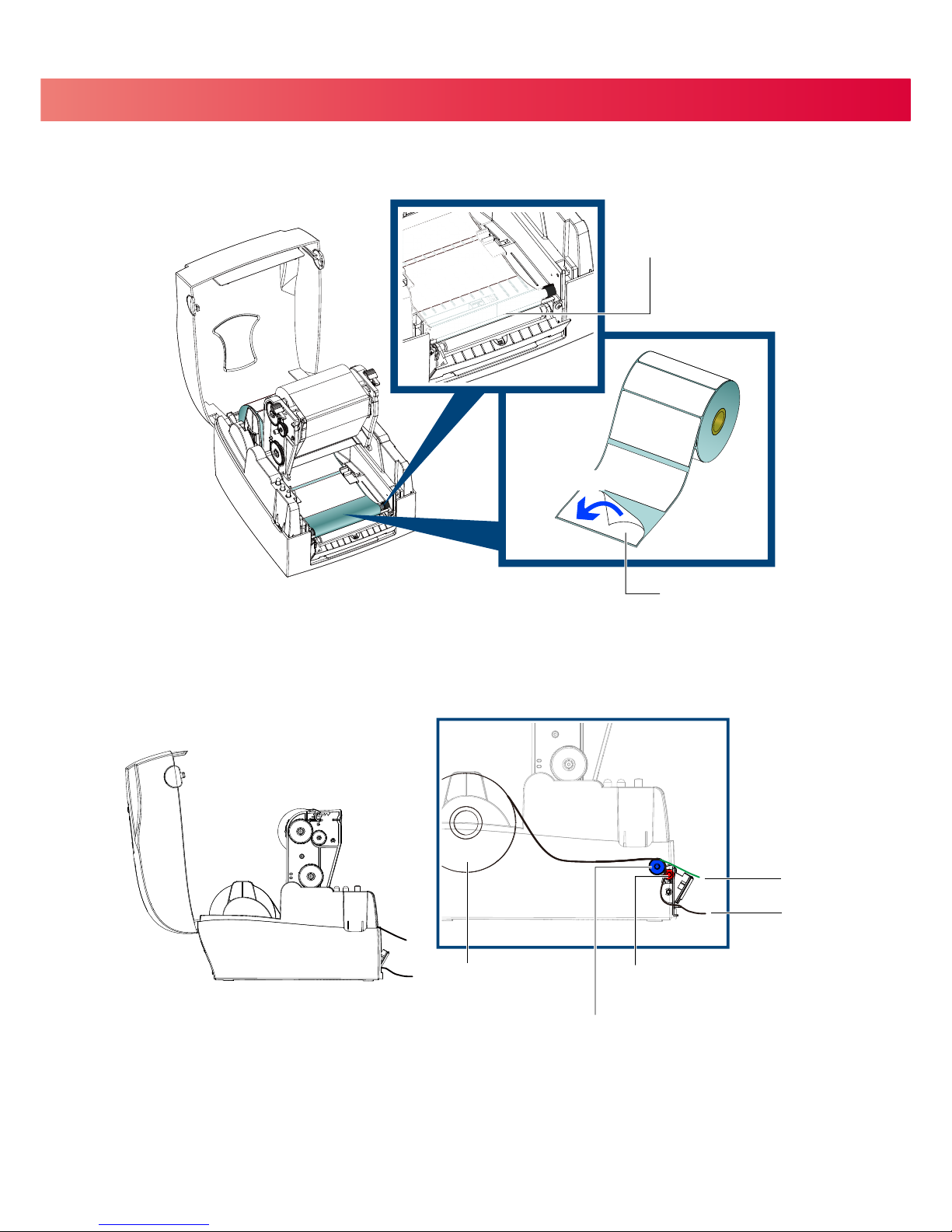
Remove the first label(s) from the liner.
Feed the label stock through the Printer as shown in the illustration below.
32
Peel label(s)
FIRST LABEL
PLATEN ROLLER
LABEL STOCK
PLATEN ROLLER
LABEL DISPENSER MODULE
PAPER FEED ROLLER
LABEL
LINER
Page 37
5 Accessories
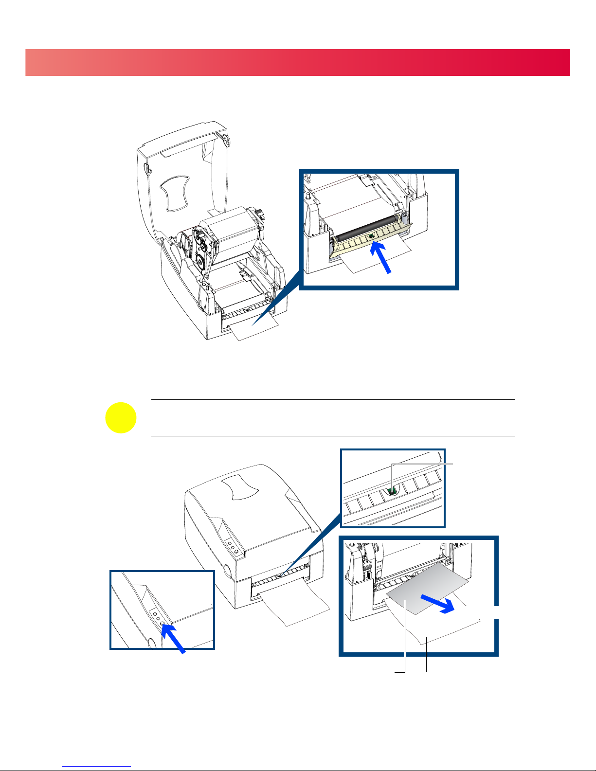
Close the Label Dispenser and the Print Mechanism to complete the installation.
Press the FEED button to feed a label.
The label will be peeled from the liner while it passes through the Label Dispenser.
33
Close
Remove the label
Press FEED
LINER
LABEL
SENSOR
=
There is a paper sensor on the Label Dispenser module. It will stop the printing if it is covered
by a label. Remove the last printed label and the printer will print next label.
NOTICE
Page 38
5 Accessories
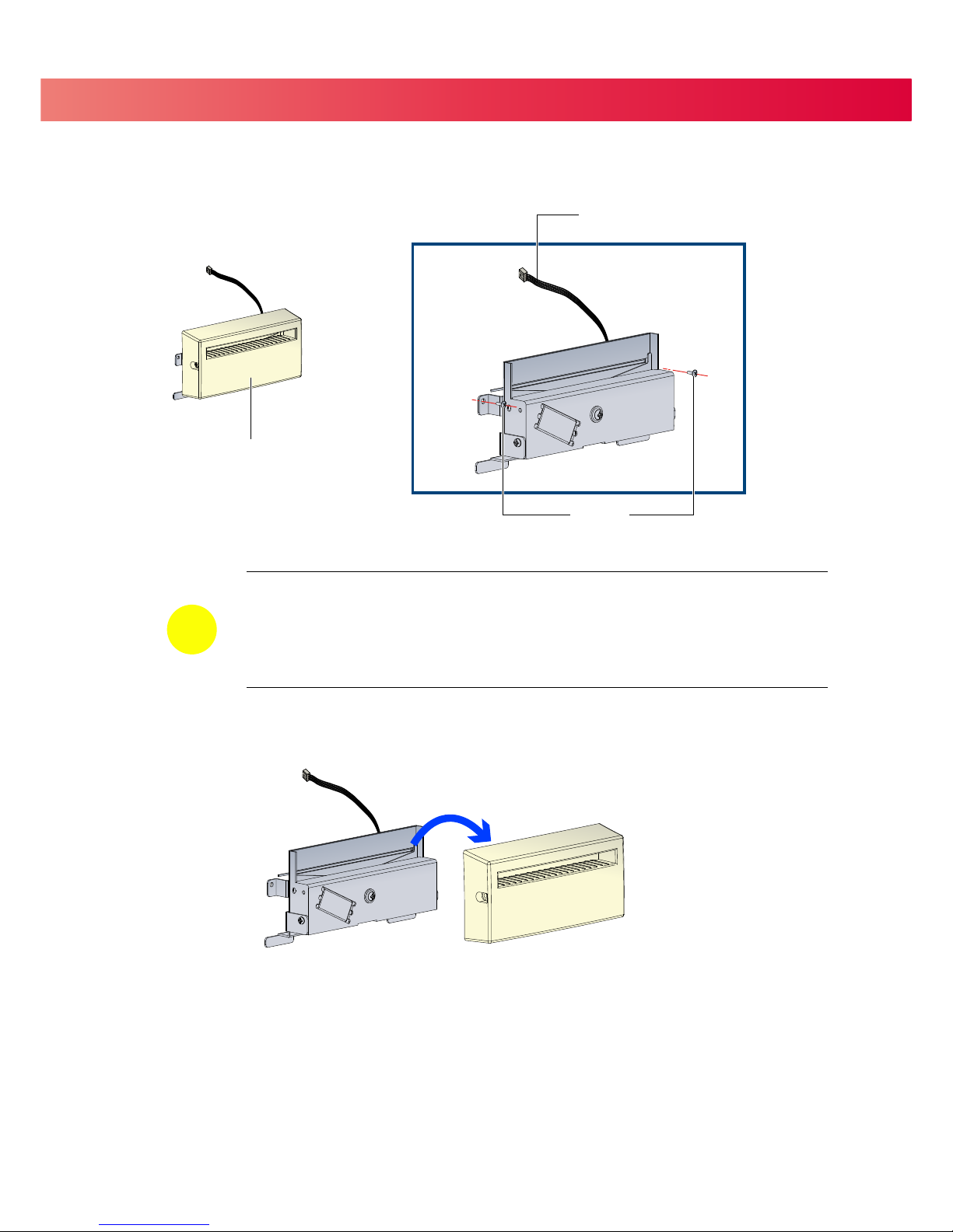
5.3 Installing The Cutter
Remove the Cutter Cover before installing the Cutter module.
Please complete the preparation steps on page 28 before installing the Cutter.
34
CONNECTION CABLE
Remove the Cutter Cover
=
Remember to turn the Printer off before installing the Cutter.
=
Do not use to cut adhesive labels! Glue residue will be left on the cutter blade and impair its
function. The cutter has a blade life of 400,000 cuts when using paper liner which is
250μm thick and 3 inches wide.
= Maximum width when using the Cutter is
116 mm.
NOTICE
SCREWS
CUTTER MODULE
Page 39
5 Accessories
35
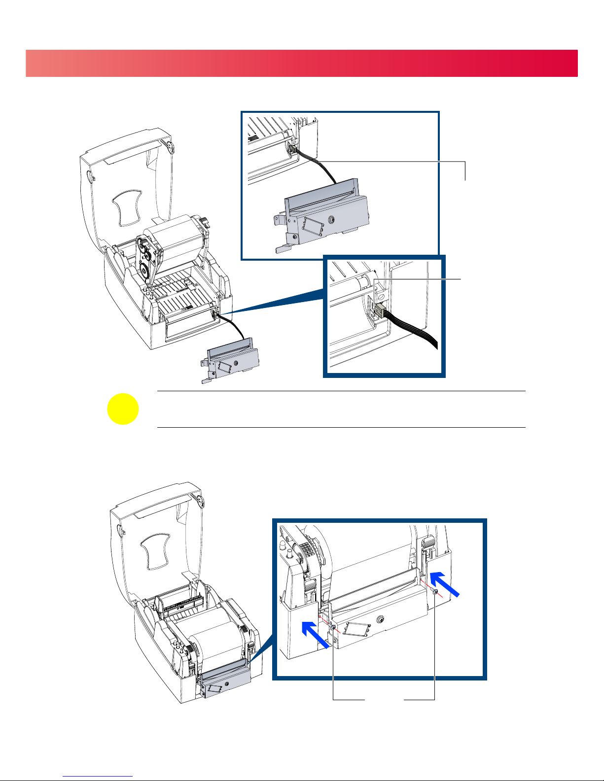
CONNECTION CABLE
UPPER JACK
=
The printer MUST be turned OFF or the motherboard may be damaged!
=
There are 2 jacks: the lower jack is for the Label Dispenser, the upper jack is for the Cutter.
NOTICE
Secure the cutter using the screws provided.
SCREWS
Connect the Connection Cable on the Cutter to the upper jack on the front of the printer as shown below.
Page 40
5 Accessories
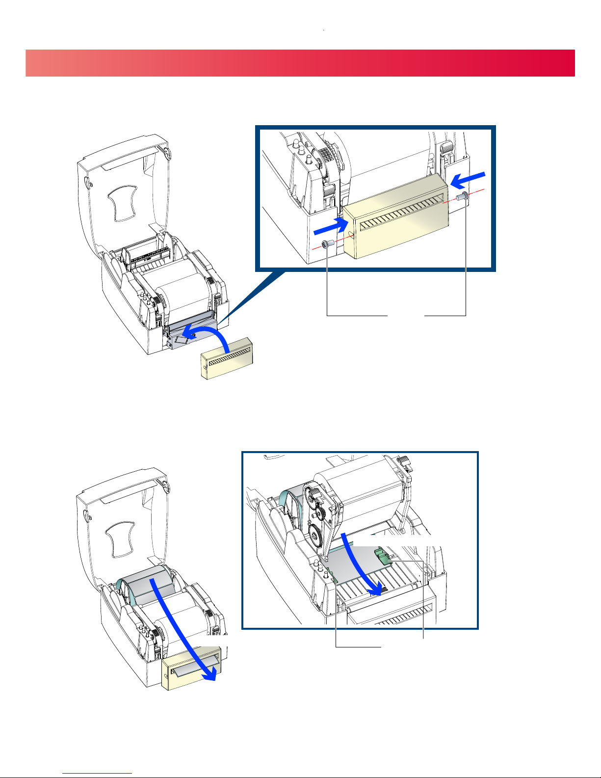
Secure the Cutter Cover using the screws provided.
Feed the labels through the Label Guides and the Cutter.
Close the print mechanism.
36
SCREWS
Through the Cutter Module
Through the Label Guides
LABEL GUIDES
Page 41
5 Accessories
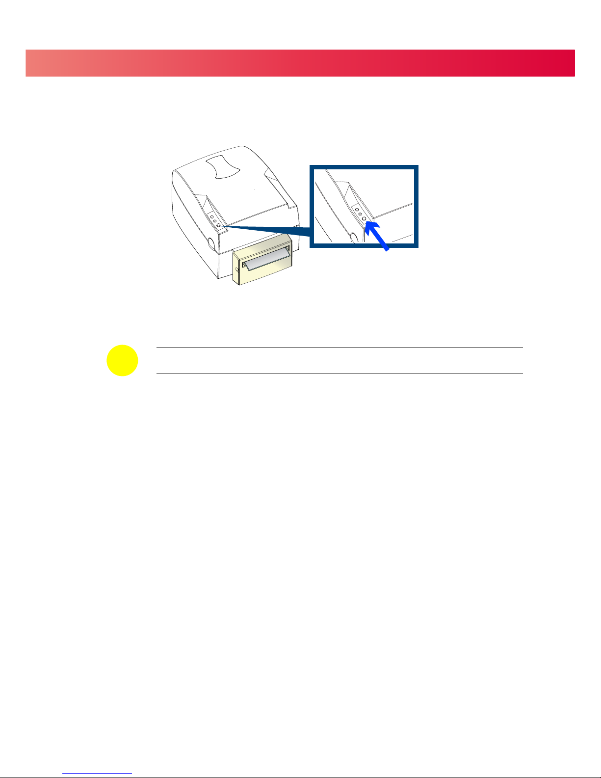
Press the FEED button to complete the Cutter installation.
37
=
We advise against using inside wound label stock with the Cutter.
NOTICE
Press FEED
Page 42
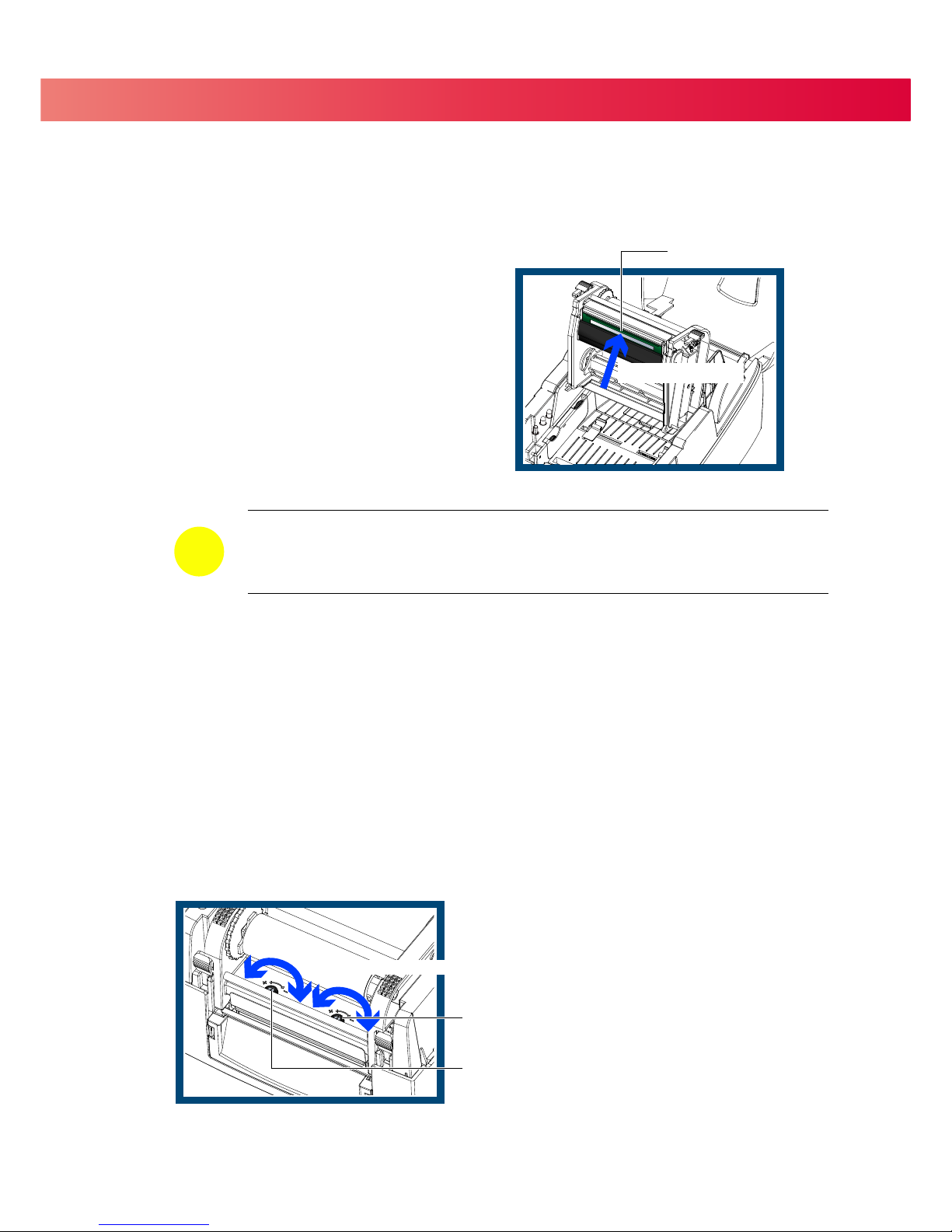
6 Maintenance And Adjustment
6.1 Cleaning the Thermal Print Head
Printing labels will cause dirt such as paper dust, particles of ink and label
adhesive to accumulate on the thermal print head. This can cause poor
print quality and incomplete print outs. When this happens, the print head
must be cleaned:
1. Turn off the printer.
2. Open the Top Cover.
3. Release the Print Mechanism.
4. Remove the ribbon.
5. Clean the print head surface (see Blue arrow) with a
special cleaning pen or a cotton swab soaked in
Isopropyl Alcohol.
6. Allow the print head to dry for 2-3 minutes before
turning the printer back on.
6.2 Adjusting the Print Head Pressure
When using a variety of label stock and ribbons, the ink may not be evenly distributed.
If there is no printed image on one side of the paper then the print head pressure must be readjusted.
1. Open the Top Cover.
2. Remove the ribbon.
3. Use a screw driver to slowly turn the Print Head Pressure Adjustment Screws to increase or decrease
the print head pressure.
38
=
The print head should be cleaned once a week or when the print media is changed.
=
To help keep the print head clean, the top cover should be closed when printing.
=
To ensure print quality and prolong print head life, do NOT use dusty or dirty print media.
NOTICE
PRINT HEAD
Clean this Surface
Turn the Adjustment Screws
Screw for adjusting the print head pressure on the right side
Screw for adjusting the print head pressure on the left side
Page 43
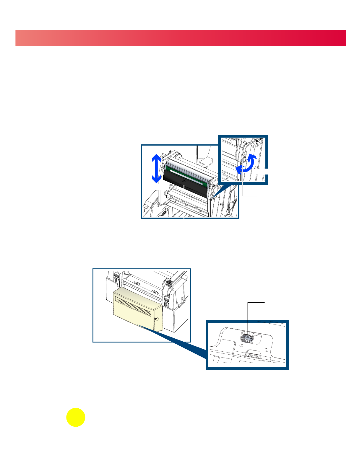
6 Maintenance And Adjustment
6.3 Adjusting the Print Line
The Print Line must be adjusted so it is positioned parallel to the paper feed roller.
1. To move the Print Head forward (Direction A)
turn the Adjustment Wheel counterclockwise ( arrow 1).
2. To move the Print Head rearward (Direction B)
turn the Adjustment Wheel clockwise ( arrow 2).
6.4 Clearing Cutter Jams
Paper can jam the Cutter during use. Please follow the below steps to clean the paper jam.
A Phillips head screw for clearing cutter jams is located on the bottom of cutter module, as shown below.
1. Turn the Printer OFF.
2. Use a Philips screwdriver to turn the screw and clear the jam.
3. Once you have cleared the paper jam, turn the Printer back ON. The cutter will automatically reset.
39
Turn the Adjustment Wheel
Direction-A
Direction-B
PRINT HEAD
ADJUSTMENT WHEEL
=
Labels should be at least 30 mm high to ensure proper functioning of the cutter.
NOTICE
PHILLIPS HEAD SCREW
1
2
Page 44

6 Maintenance And Adjustment
6.5 Troubleshooting
40
=
If any problems occur that are not described here, please contact your reseller.
NOTICE
♦ Check the power supply.
Problem
Solution
The printer is switched on but the LED
does not light up.
One or both LEDs lights up red and
printing has stopped
♦ Check for software setting or program command errors.
♦ Look for the error in Section 3.3 Error Alerts
♦ Check if the print mechanism is closed correctly.
The label stock passes through the printer
but no image is printed.
♦ Check that the ribbon is installed with the inked side facing the
label media.
♦ Select the correct printer driver.
♦ Select the correct label stock and print mode.
The label stock jams during printing.
♦ Clear the paper jam.
Check that the print head is clean.
There is no printed image on some parts
of the label.
♦ Check if there is any label or ribbon stuck on the thermal
print head.
♦ Check for errors in the application software.
♦ Check if the starting position has been set correctly
♦ Check the ribbon for wrinkles.
There is no printed image on part of the
label or the image is blurred.
♦ Check the thermal print head for dust or other dirt.
♦ Use the internal “~T” command to perform a Test Print and check if
the print head can print across the entire width.
♦ Check the quality of the print media.
The printed image is positioned
incorrectly.
♦ Check if there is paper or dust covering the label sensor.
♦ Check if the label stock is suitable for use. Contact your reseller.
♦ Check the paper guide.
Skipping labels during printing.
♦ Check the label height setting.
♦
♦
The printed image is blurred.
♦ Check the print darkness setting.
♦ Check if the print head is dirty.
The cutter does not cut off the labels in a
straight line.
♦ Check if the label stock is installed correctly.
The cutter does not cut off the labels
completely.
♦ Check if the label thickness exceeds 0.2 mm.
When using the cutter, the labels are not
fed through or are cut off incorrectly.
♦ Check if the cutter has been correctly installed.
♦ Check if the paper guides are sticky.
The label dispenser is not functioning
normally.
♦ Check if there is dust on the label dispenser sensor.
♦ Check if the label stock is installed properly.
Check if there is dust covering the label sensor.
Perform a label calibration.
Page 45
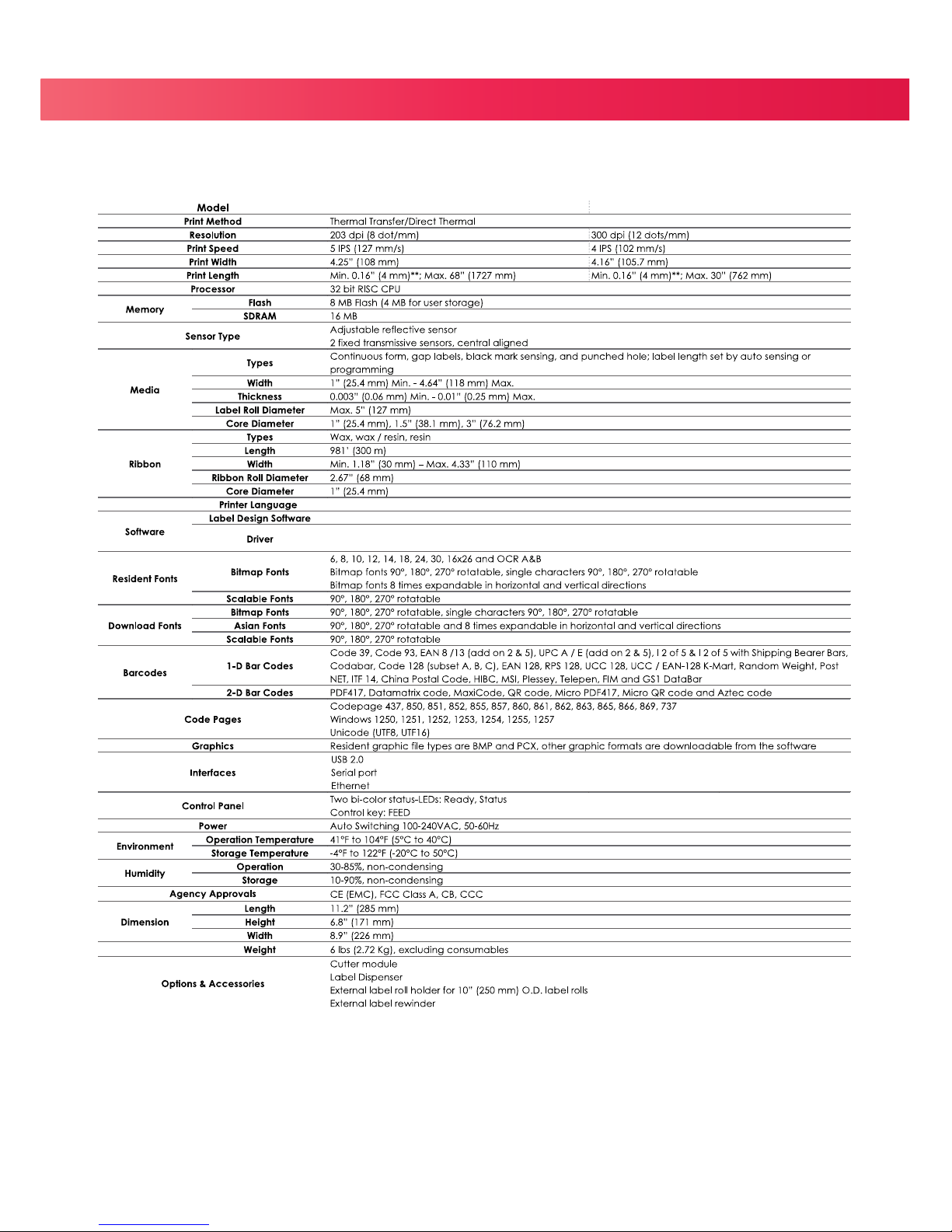
41
APPENDIX
Product
Specifications
Notice
Specifications are subject to change without notice. All company and/or product names are trademarks and/or registered
trademarks of their respective owners.
EASYLABEL Start
TPL
V-425E V-434E
Windows and CUPS (Linux and Mac)
Page 46

42
4 Serial Port
Default Settings: Baud rate 9600, no parity, 8 data bits, 1 stop bit, XON/XOFF protocol and RTS/CTS.
4 USB
Connector Type : Type B
RS232 HOUSING (9-pin to 9-pin)
DB9 Socket
DB9 Plug
---
1 1
+5V,max 500mA
RXD
2 2
TXD
TXD
3 3
RXD
N/C
4 4
N/C
GND
5 5
GND
DSR
6 6
RTS
RTS
7 7
CTS
CTS
8 8
RTS
N/C
9 9
N/C
PC Printer
Pin NO. 1 2 3 4
Function
VBUS
D-
D+
GND
APPENDIX
Interface
 Loading...