

Page 1
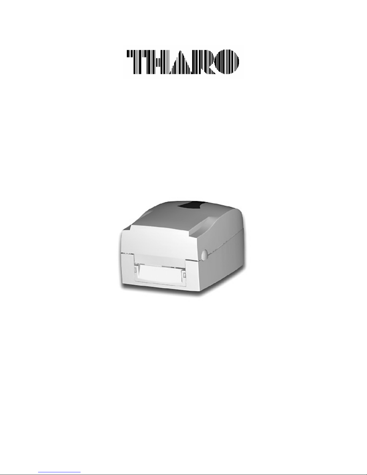
V-Series Plus
User’s Manual
Rev. Oct 2009
Page 2

FCC COMPLIANCE STATEMENT
FOR AMERICAN USERS
This equipment has been tested and found to comply with the limits for a CLASS A digital device,
pursuant to Part 15 of the FCC Rules. These limits are designed to provide reasonable protection against
harmful interference when the equipment is operated in a commercial environment. This equipment
generates, uses, and can radiate radio frequency energy and, if not installed and used in accordance
with the instructions, may cause harmful interference to radio communications. Operation of this
equipment in a residential area is likely to cause harmful interference in which case the user will be
required to correct the interference at own expense.
EMS AND EMI COMPLIANCE STATEMENT
FOR EUROPEAN USERS
This equipment has been tested and passed with the requirements relating to electromagnetic
compatibility based on the standards EN 55022:1998+A1:2000+A2:2003, CISPR 22 , Class A EN
55024:1998+A1:2001+A2:2003, IEC 61000- 4 Series EN 61000-3-2 / 2000 & EN 61000-3-3 / 1995.
The equipment also tested and passed in accordance with the European Standard EN55022 for the both
Radiated and Conducted emissions limits.
V-SERIES PLUS
TO WHICH THIS DECLARATION RELATES
IS IN CONFORMITY WITH THE FOLLOWING STANDARDS
EN55022 : 1998,CLSPR 22, Class A / EN55024 : 1998IEC 61000-4 Serial / EN61000-3-2 : 2000 / EN
6100-3-3 : 1995 / CFR 47, Part 15/CISPR 22 3rd Edition : 1997, Class A / ANSI C63.4 : 2001 / CNS
13438 / IEC60950-1 : 2001 / GB4943 : 2001 / GB9254 : 1998 / GB17625.1 : 2003 /EN60950-1 : 2001
CAUTION
Danger of explosion if battery is replaced incorrectly.
Only replace battery with an equivalent type as recommended by the manufacturer.
Dispose of used batteries according to the manufacturer’s instructions.
Copyright and Trademark Notice
© 2009 by Tharo Systems, Inc.
It is illegal to photocopy or electronically transmit a facsimile of this manual or any portion of
its contents for any means or purpose without the publisher’s permission. Fines of up to
$10,000.00 may be imposed for violation.
All brand or product names are trademarks or registered trademarks of their respective companies.
Specifications are subject to change without notice.
1
Page 3

Warranty Information .........................................................................................................................................3
1. Product Description ......................................................................................................................................4
General Information.....................................................................................................................................4
Printer Options ..............................................................................................................................................4
2. General Safety Tips......................................................................................................................................6
3. Unpacking the Printer and Accessories ....................................................................................................6
4. Identifying Components..............................................................................................................................7
5. Printer Setup .................................................................................................................................................9
USB Installation ..........................................................................................................................................10
6. Control Panel ...............................................................................................................................................11
General Description and Operation.........................................................................................................11
Interpreting LED Messages.......................................................................................................................11
Printer Setup................................................................................................................................................11
Auto Sensing................................................................................................................................................12
Turning the See-through Sensor on/off ................................................................................................12
7. Loading Media .............................................................................................................................................13
Ribbon Installation .....................................................................................................................................13
Label Installation ........................................................................................................................................15
Label Roll Core Installation Instructions................................................................................................16
Direct Thermal / Thermal Transfer Mode Switch.................................................................................17
Card / Hang tags Installation...................................................................................................................17
8. Installing the Printer’s Optional Accessories.........................................................................................18
V-Series Stripper Sensor Module Installation Instructions................................................................18
Cutter Module Installation Instructions .................................................................................................21
Compact FLASH Card Slot module with Real-Time Clock ..................................................................23
Appendix A. Communication Interfaces .....................................................................................................24
Parallel Interface.........................................................................................................................................24
Serial Interface ...........................................................................................................................................24
USB Interface ..............................................................................................................................................24
Appendix B. Error Messages / Troubleshooting ........................................................................................25
Self Test........................................................................................................................................................25
Dump Mode..................................................................................................................................................25
LED Error Message Descriptions..............................................................................................................26
Problems and Recommended Solutions.................................................................................................27
Appendix C. Maintenance and Adjustment ................................................................................................28
Cleaning the Thermal Printhead ..............................................................................................................28
Thermal Printhead Print Line Adjustment .............................................................................................29
Thermal Printhead Spring Box Pressure Adjustment..........................................................................29
Thermal Printhead Replacement .............................................................................................................30
Upgrading the Printer’s Firmware ...........................................................................................................31
Downloading True Type Fonts to the Printer’s Flash Memory ..........................................................32
Clearing Cutter Jams .................................................................................................................................33
Cleaning Adhesive from the Cutter Blade .............................................................................................33
2
Page 4

Warranty Information
The THARO V-Series Plus Printers are warranted against defects in material or workmanship for 12 months (365
days) from the date of original shipment by THARO SYSTEMS, INCORPORATED. This warranty does not cover
normal wear and tear and shall be null and void if the equipment is modified, improperly installed or used, damaged
by accident or neglect, or in the event any parts are improperly installed or replaced by the user.
Since Printhead wear is part of normal operations, a Printhead warranty of 3 months (90 days) from the date of
original shipment by THARO SYSTEMS, or 25,000 linear meters of use, whichever comes first. To qualify for this
warranty, the Printhead must be returned to THARO or another authorized service center. Although the user is not
required to purchase THARO brand supplies (media and/or ribbons), to the extent it is determined that the use of
other supplies (media and/or ribbons) shall have caused any defect in the thermal Printhead for which a warranty
claim is made, the user shall be responsible for THARO's customary charges for labor and materials to repair such
defect. To the extent that it is determined that failure to follow the preventive maintenance schedule and
procedures listed in the User Guide shall have caused any defect in the thermal Printhead for which a warranty claim
is made, this limited warranty shall be void. Any Printhead returned to THARO with scratches or abrasions on the
Printhead at the point of failure will be deemed abused and no warranty replacement will be provided.
THARO SYSTEMS' SOLE OBLIGATION UNDER THIS WARRANTY SHALL BE TO FURNISH PARTS AND LABOR FOR THE
REPAIR OR REPLACEMENT OF PRODUCTS FOUND TO BE DEFECTIVE IN MATERIAL OR WORKMANSHIP DURING THE
WARRANTY PERIOD.
As a condition of this warranty, the user must: (a) obtain a THARO Return Authorization for the Printer, or
subassembly(s); (b) ship the Printer or subassembly(s), transportation prepaid to the authorized service location;
and (c) include with the Product or subassembly(s) a written description of the claimed defect. Unless THARO
SYSTEMS authorizes return of the entire Product, the user shall return only the subassembly(s). Products returned
shall be packaged in the original packing and shipping container or comparable container. In the event equipment
is not so packaged or if shipping damage is evident, it will not be accepted for service under warranty. Surface
transportation charges for the return of the Printer to the customer shall be paid by THARO SYSTEMS within the 48
contiguous states and the District of Columbia. Customer shall pay shipping costs, customs clearance, and other
related charges outside the designated area. If THARO SYSTEMS determines that the Product returned to it for
warranty service or replacement is not defective as herein defined, BUYER shall be subject to a minimal labor charge
and all costs of handling and transportation.
Warranty Exclusions and Conditions
The above warranties are in lieu of all other warranties, expressed or implied, oral or written, statutory or otherwise,
including any implied warranty of merchant-ability or fitness for a particular purpose.
THARO SYSTEMS shall not be responsible for the specific application to which any Products are applied, including
but not limited to compatibility with other equipment.
All statements, technical information and recommendations relating to THARO Products are based upon tests
believed to be reliable but do not constitute a guarantee or warranty.
THARO SYSTEMS SHALL NOT, UNDER ANY CIRCUMSTANCES WHATSOEVER, BE LIABLE TO BUYER OR ANY OTHER
PARTY FOR LOST PROFITS, DIMINUTION OF GOODWILL OR ANY OTHER SPECIAL OR CONSEQUENTIAL DAMAGES
WHATSOEVER WITH RESPECT TO ANY CLAIM HEREUNDER. IN ADDITION, THARO SYSTEMS' LIABILITY FOR
WARRANTY CLAIMS SHALL NOT, IN ANY EVENT, EXCEED THE INVOICE PRICE OF THE PRODUCT CLAIMED
DEFECTIVE, NOR SHALL THARO SYSTEMS BE LIABLE FOR DELAYS IN REPLACEMENT OR REPAIR OF PRODUCTS
No salesperson, representative or agent of THARO SYSTEMS is authorized to make any guarantee, warranty, or
representation in addition to the foregoing warranty.
NO WAIVER, ALTERATION, ADDITION, OR MODIFICATION OF THE FOREGOING WARRANTIES SHALL BE VALID
UNLESS MADE IN WRITING AND SIGNED BY AN EXECUTIVE OFFICER OF THARO SYSTEMS.
3
Page 5

1. Product Description
General Information
The THARO V-424 Plus and V-434 Plus Printers are Thermal Transfer/Direct Thermal label Printers
designed for use on a desktop. The compact V-424 Plus and V-434 Plus feature a small footprint to fit
your work environment. The V-Series Plus Printers are constructed of a durable, impact-resistant
composite with a media window for easy viewing and monitoring of remaining supplies.
The THARO V-424 Plus features a printhead density of 8 dots/mm (203 dots/in) and a maximum print
length of 1727mm (68”). The THARO V-434 Plus features a printhead density of 12 dots/mm (300
dots/in) and a maximum print length of 762mm (30”).
The THARO V-424 Plus and V-434 Plus Printers provide 125mm (4.92”) diameter label roll and 300
meter length ribbon capacities giving you the benefit of less downtime and increased production. Both
Printers come standard with built-in USB for high-speed data transfer from your PC.
Accessories available for the THARO V-424 Plus and V-434 Plus Printers include a Cutter for ticket or
receipt printing applications, an internal Ethernet Card for network connectivity, a Compact FLASH Card
Slot module with a Real-Time Clock for time and date stamping of labels and a Stripper Sensor Module
so the Printers can be used in strip-and-peel applications.
Printer Options
Stripper Sensor Module
The Stripper Sensor Module is used to sense printed labels in strip-and-peel applications. With the
Stripper Sensor Module installed, the printed labels are presented for removal and the used liner feeds
from the Printer and collects on the floor.
Cutter
The optional Cutter can be used to cut labels or tag stock up to a 10-mil (.254mm) thickness. Cutter
options include a choice of: cut after each label, cut after a specific quantity of labels, or cut at the end
of a print job.
Compact FLASH Card Slot module with Real-Time Clock
The Printer has the ability to use internal Flash memory for storing downloaded files including graphics
and fonts. This option provides a slot which allows you to install a Compact FLASH card to be used as
additional FLASH memory above and beyond the 4MB of FLASH that is standard in the Printer. This
increases the available space for the storage of these files. The Printer supports Compact FLASH Cards
from 128MB to 1GB. This module also includes a Real-Time Clock for the Time and Date stamping of
your labels.
Internal Ethernet Adapter Card
The Internal Ethernet Adapter Card provides networking capability to the V-424 Plus and V-434 Plus.
External Label Stand
The External Label Stand allows the use of label rolls with an outside diameter of 203.2 (8”).
EASYLABEL® - Label Design Software for Windows
EASYLABEL® labeling software allows you to drive your Printer and create a full range of label formats
with a minimum of effort. EASYLABEL can be installed under Microsoft Windows® on IBM PCs and
compatibles. For further information about EASYLABEL, please contact your THARO Reseller.
4
Page 6
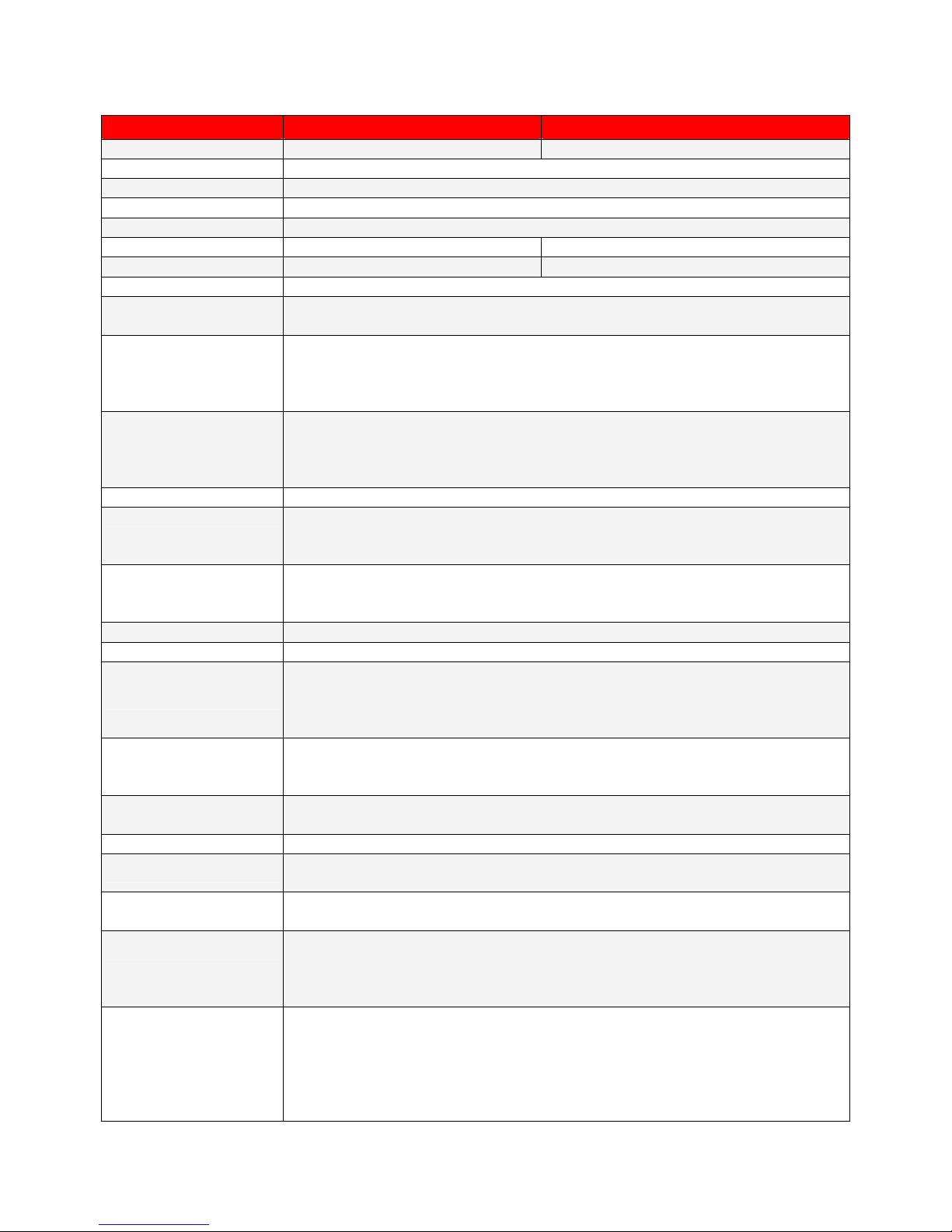
Technical Specifications
Type: Ink outside thermal transfer ribbons (wax, resin and wax/resin) in
Model V-424 Plus V-434 Plus
Resolution 203 dpi (8 dot/mm) 300 dpi (12 dot/mm)
Print Mode Thermal Transfer / Direct Thermal
CPU 32 Bit
Memory 4MB Flash, 8MB SDRAM
Print Speed 50.8mm (2”) ~ 101.6mm (4”)/sec
Print Length 12mm (0.47”) ~ 1727mm (68”) 12mm (0.47”) ~ 762mm (30”)
Max Print Width 108mm (4.25”) 105.7mm (4.16”)
Sensor Type Moveable Reflective sensor; Fixed transmissive; center aligned
Sensor Detection
Media
Type: Label gap and black mark sensing
Detection: Label length auto sensing and/or program command setting
Label Roll: Max. 125mm (4.92”)
Core Diameter: 25.4mm (1”), 38.1mm (1.5”), 76.2mm (3”)
Width: 25.4mm (1”) ~ 118mm (4.64”)
Thickness: 0.06mm (0.002”) ~ 0.25mm (0.009”)
Length: 300m (981’)
- Specifications are subject to change without notice.
Ribbon
Printer Language TPL (Tharo Programming Language)
Software
Resident Fonts
Downloadable Fonts Windows Bit-map fonts, TrueType fonts and Asian fonts
Image Handling BMP and PCX
Bar Codes
Interfaces
Control Panel
Power Auto Switching 100/240VAC, 50/60 Hz
Environment
Humidity
Printer Dimensions
Options
widths of 30 to 110mm (1.88” to 4.33”). Core inner diameter 25.4mm
(1”). Maximum ribbon roll diameter 68mm (2.67”).
EASYLABEL® Start
Microsoft Windows Drivers, CUPS (Common UNIX Printing System)
Driver
11 resident alphanumeric fonts (including OCR A & B), are expandable
eight times horizontally and vertically.
Scalable Font (Code Page 850 & 852)
Code 39, Code 93, Code 128 (subsets A, B, C), UCC/EAN-128, UPC-A,
UPC-E, UPC and EAN 2 or 5 digit extensions, I 2 of 5, EAN-8, EAN-13,
Codabar, Postnet, DUN 14, MaxiCode, Plessey, Telepen, FIM, China
Postal Code, RPS 128, PDF417, Data Matrix & QR Code
RS-232 Serial (Baud rate 4800 ~ 115200, XON/XOFF, DSR/DTR)
USB(2.0)
Parallel
Two Bi-color LEDs: Ready and Status
Function Key: FEED
Operation: 41° F to 104° F (5° C to 40° C)
Storage: -4° F to 122° F (-20° C to 50° C)
Operation: 30-85%, non-condensing. Free air.
Storage: 10-90%, non-condensing. Free air.
Length: 285mm (11.2”)
Height: 171mm (6.8”)
Width: 226mm (8.9”)
Weight: 2.72Kg (6.0 lbs)
Cutter
Stripper Sensor Module
Compact FLASH Card Slot module with Real-Time Clock
Internal Ethernet Adapter
External Label Stand
EASYLABEL Silver, Gold, Platinum or Multi-User
5
Page 7

2. General Safety Tips
CAUTION!
During the print process the Printhead will become hot. Do NOT attempt to clean the Printhead
until it has had time to cool.
The Printhead is the Most Fragile part of your Printer. Do NOT use sharp or hard objects to clean
the Printhead. Do NOT touch the glass surface of the Printhead with your hand.
This Printer is built exclusively to print labels, tickets and tags, continuous paper, etc. Only use
media that is recommended for a direct thermal or thermal transfer Printer.
The Printer is configured for input voltages of 110 to 240 V. Connect only to a power outlet with
a grounded contact. Always ensure the Printer is switched OFF before connecting the power
cord to an electrical outlet.
Do not expose the Printer to moisture or operate it in wet or damp areas.
Remove the power cord from the rear of the Printer when disconnecting or attaching accessories
such as Stripper Sensors, Cutters, etc.
3. Unpacking the Printer and Accessories
Check the condition of the packaging and contents for possible damage during transit.
NOTICE: Please retain original boxes and all original packing materials in
case the Printer must be returned.
In addition to this manual the following items should be included with your Printer:
Bar Code Printer
Power Cord (110V or 230V)
Switching Power Adapter
Ribbon Shaft, Qty. 2
Label Roll Core
Empty Ribbon Roll
Quick Start Guide
Accessories CD: Includes Label Software, Manuals, Windows Drivers and CUPS Driver.
The following additional items are necessary for generating labels from your Printer:
Serial, Parallel, or USB cable
Applicable media (label stock/ribbon)
6
Page 8
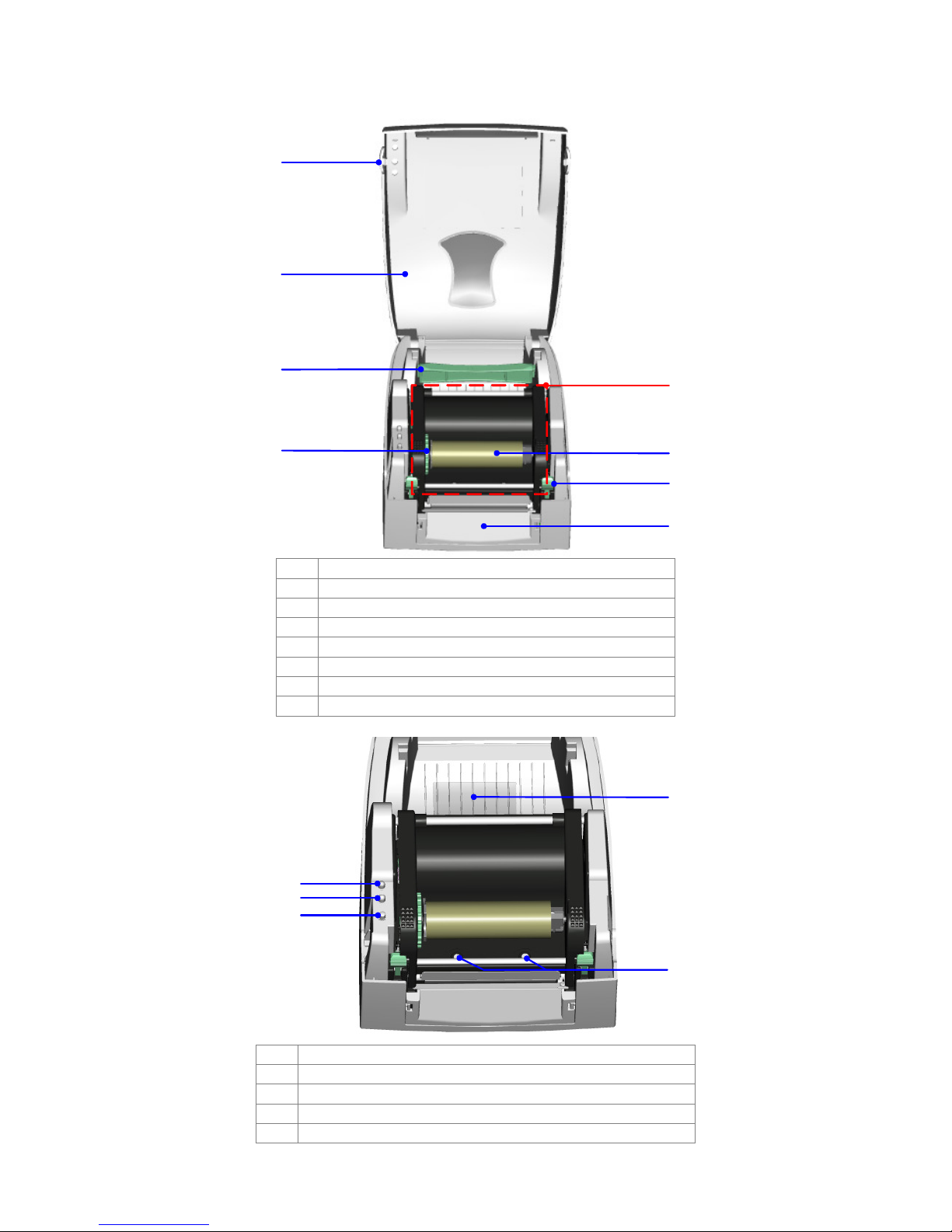
4. Identifying Components
1
2
3
5
4
1. Open Cover Button
2. Top Cover
3. Label Roll Core
4. Ribbon Rewind Wheel
5. Print Mechanism
6. Ribbon Rewind Shaft + Empty Take Up Core
7. Head Latches (left/right)
8. Front Cover Panel
1
2
3
6
7
8
4
1. LED (Ready)
2. LED (Status)
3. FEED Key
4. Compact FLASH Card Slot Module Cover
5. Printhead Pressure Adjustment Screw (left/right)
5
7
Page 9
1
Print Line Adjustment
4
2
3
5
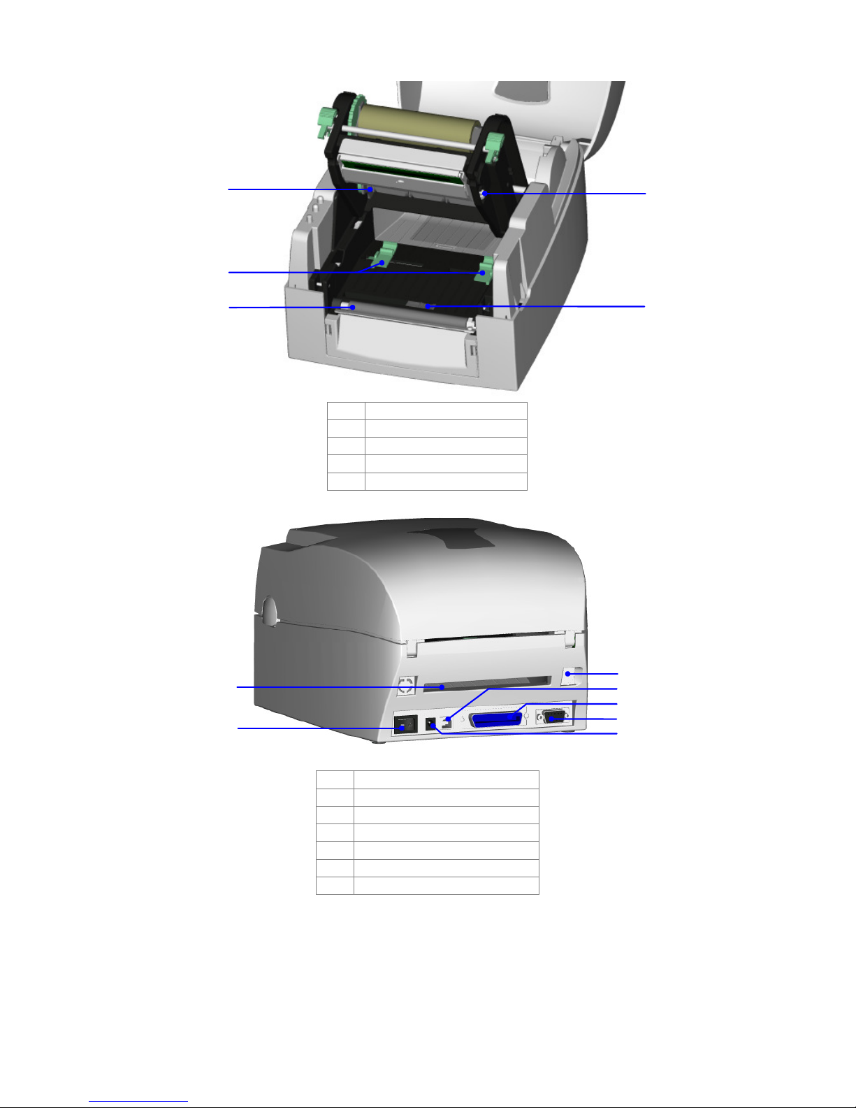
1. Ribbon Supply Shaft
2. Label Guide
3. Platen Roller
4.
5. Label Sensor
3
1
4
5
2
6
7
1. Fan-Fold Label Slot
2. Power Switch
3. Ethernet Socket (Option)
4. USB Port
5. Parallel Port
6. Serial Port (RS-232)
7. Power Socket
8
Page 10
5. Printer Setup
CAUTION!
When choosing a location for the Printer, ensure that the Printer and
operator remain dry. If the Printer or the operator get wet, serious
injury to the operator or damage to the Printer may occur.
CAUTION!
Make sure that the Printer’s power switch is in the “O” or “Off” position
before proceeding with the installation.
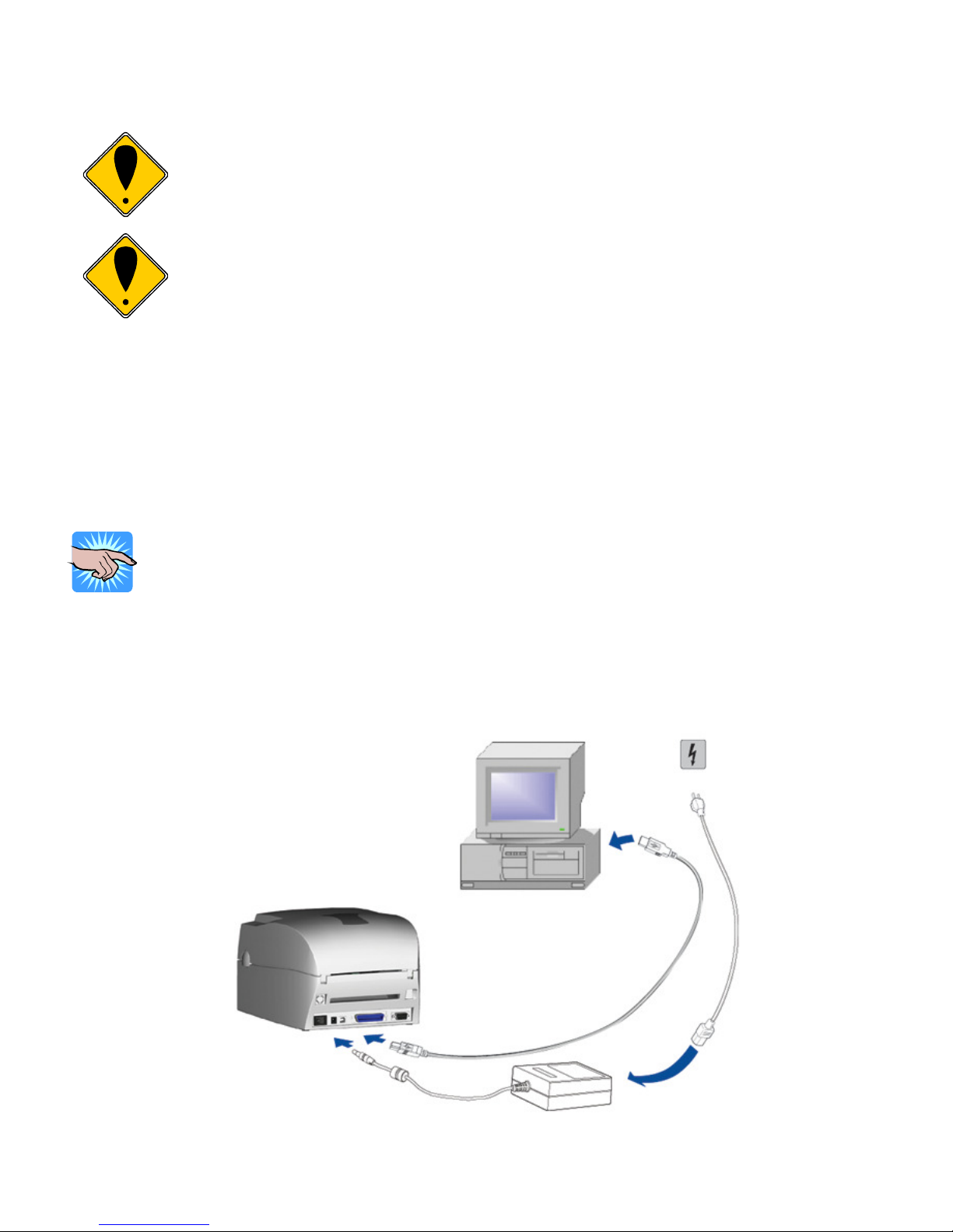
1. Plug the lead from the Switching Power Adapter into the Printer’s power socket.
2. Plug the supplied power cord into the Switching Power Adapter and then plug the other end of the
power cord into a grounded outlet.
3. Select the correct cable for the chosen interface. The Printer can be directly connected to the PC in
one of 3 ways: USB, parallel, or serial. For the connection to the USB port use a suitable USB
cable. For the connection to the PC’s parallel port use a suitable parallel interface cable. If the serial
interface is used make sure the proper serial cable is used. You can find pin assignments and
descriptions for all three interfaces connectors in Appendix A.
NOTICE!
For Serial communications make sure that the Serial Port Settings in the
Printer are configured the same as in the software you will be using with the
Printer.
4. Connect the Printer to the computer with the selected cable. Then secure the cable using any
screws or clips attached to the connectors. These prevent the connection from working loose.
5. Turn the Printer on, the Ready LED will glow green when the Printer is on.
9
Page 11
USB Installation
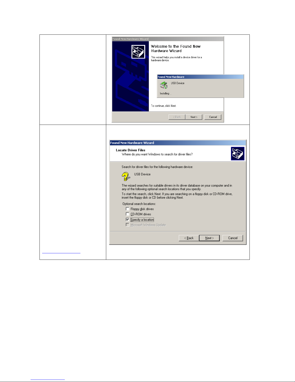
1. USB is a Plug & Play
facility. Once the
USB cable is
connected from PC
to the Printer, the PC
will automatically
detect the new
device and begin the
installation process.
2. Select ‘Specify a
location’ and specify
the path of the
Printer driver.
3. Follow the
instructions in the
Wizard to complete
the installation.
Note: These instructions
are only for use when
using Windows Drivers.
When using label
software such as
EASYLABEL® you can
disable the prompting for
Windows Drivers.
Consult the
knowledgebase on our
website at
www.tharo.com for
detailed instructions.
10
Page 12
Mode. Refer to Appendix B
6. Control Panel
General Description and Operation
FEED Key
Pressing the FEED key will cause the Printer to advance the media (according to media type) to a
specified stop position. If the Printer is loaded with continuous media the Printer will FEED the media
out a certain length. If the Printer is loaded with labels with gaps or black marks, the Printer will
advance one label at a time. If the label is not sent out in a correct position the sensor must be
calibrated. Follow the instructions for Sensor Calibration in the Maintenance and Adjustment section of
this manual.
Interpreting LED Messages
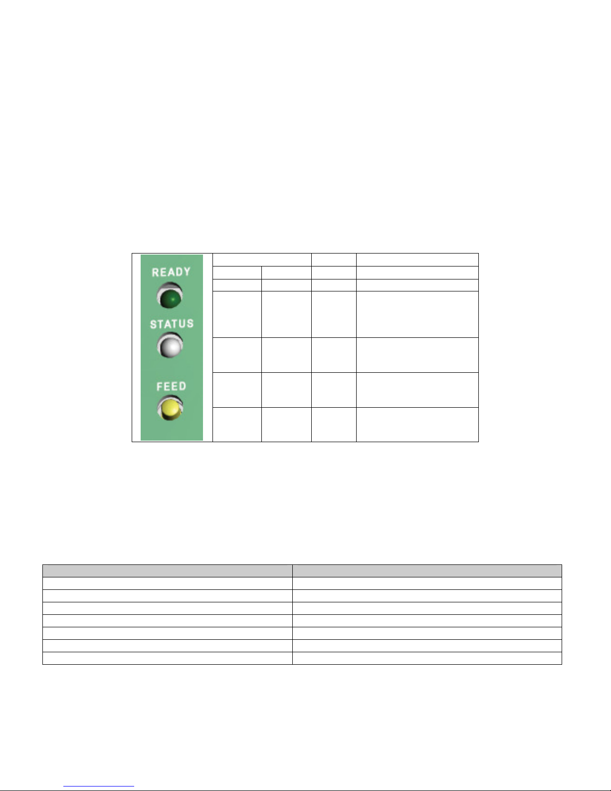
LED Beep Description
Ready Status
Green 1 Normal
Red
(Flashing)
Green
(Flashing)
Orange
Or
Green*
*If both of READY and STATUS lights are green when doing Auto-Sensing, then the See-through Sensor
is on. If both of READY and STATUS lights are orange, then the See-through Sensor is off.
Orange 3
Orange 3
Orange
Or
Green*
Red
(Flashing)
Printer Setup
By holding down the FEED key and turning the power on, you will be able to change the Printer settings
depending on how many times the beeps before the FEED key is released. When the Printer is first
powered up, the Printer will beep 3 times quickly, and then will beep slowly after that.
Printer Setting Slow Beeps
Self Test 0 beeps
Auto Sensing 1 beep
Dump Mode On 2 beeps
Direct Thermal 3 beeps
Thermal Transfer 4 beeps
See Through Sensor ON 5 beeps
Top of Form ON/OFF 6 beeps
11
The Printer is printing a
Self-Test Label. Refer to
Appendix B for more
information.
The Printer is in Dump
for more information.
Printer is in Auto-Sensing
3
Mode.
The Printer is in firmware
download mode.
Page 13

Auto Sensing
Using Auto Sensing the Printer automatically detects and records the label type and length (gap or black
mark paper). Then the Printer can accurately detect the label positions.
1. Adjust the Moveable Sensor so that it is located in a position to sense the label gaps or black marks.
2. Turn the Printer Off and press and hold the FEED key.
3. Turn the Printer On while holding down the FEED key.
4. The Printer will beep three times. Continue to hold the FEED key down; the Printer will beep again.
Then release the FEED key.
5. The Printer will now detect and record the label size/length.
NOTICE!
If both of READY and STATUS lights are green when doing Auto-Sensing,
then the See-through Sensor is on. If both of READY and STATUS lights are
orange, then the See-through Sensor is off.
Turning the See-through Sensor on/off
There are two types of Media Sensor in V-Series Plus Printers – a Reflective Sensor and a See-through
Sensor. By default, the Reflective Sensor is turned on and the See-through Sensor is turned off.
The Reflective Sensor may not be able to detect the label gap on labels with thick liner, colored liner, or
graphics. In these cases the See-through Sensor would need to be enabled.
To turn the See-through Sensor on:
1. Turn the Printer Off and press and hold the FEED key.
2. Turn the Printer On while holding down the FEED key.
3. The Printer will beep three times. Continue to hold the FEED key down; wait for the STATUS light
turn red and READY light flash green, then release the FEED key.
4. The Printer will automatically print “SEE-THROUGH SENSOR IS ON”. This indicates that the
See-through Sensor is turned on (and the Reflective Sensor is turned off).
NOTICE!
To turn the See-through Sensor off, repeat above-mentioned procedures.
Then the Printer will print “SEE-THROUGH SENSOR IS OFF” to indicate that
the See-through Sensor is turned off and the Reflective Sensor is now on.
NOTICE!
If both of READY and STATUS lights are green when doing Auto-Sensing,
then the See-through Sensor is on. If both of READY and STATUS lights are
orange, then the See-through Sensor is off.
12
Page 14
7. Loading Media
Ribbon Installation
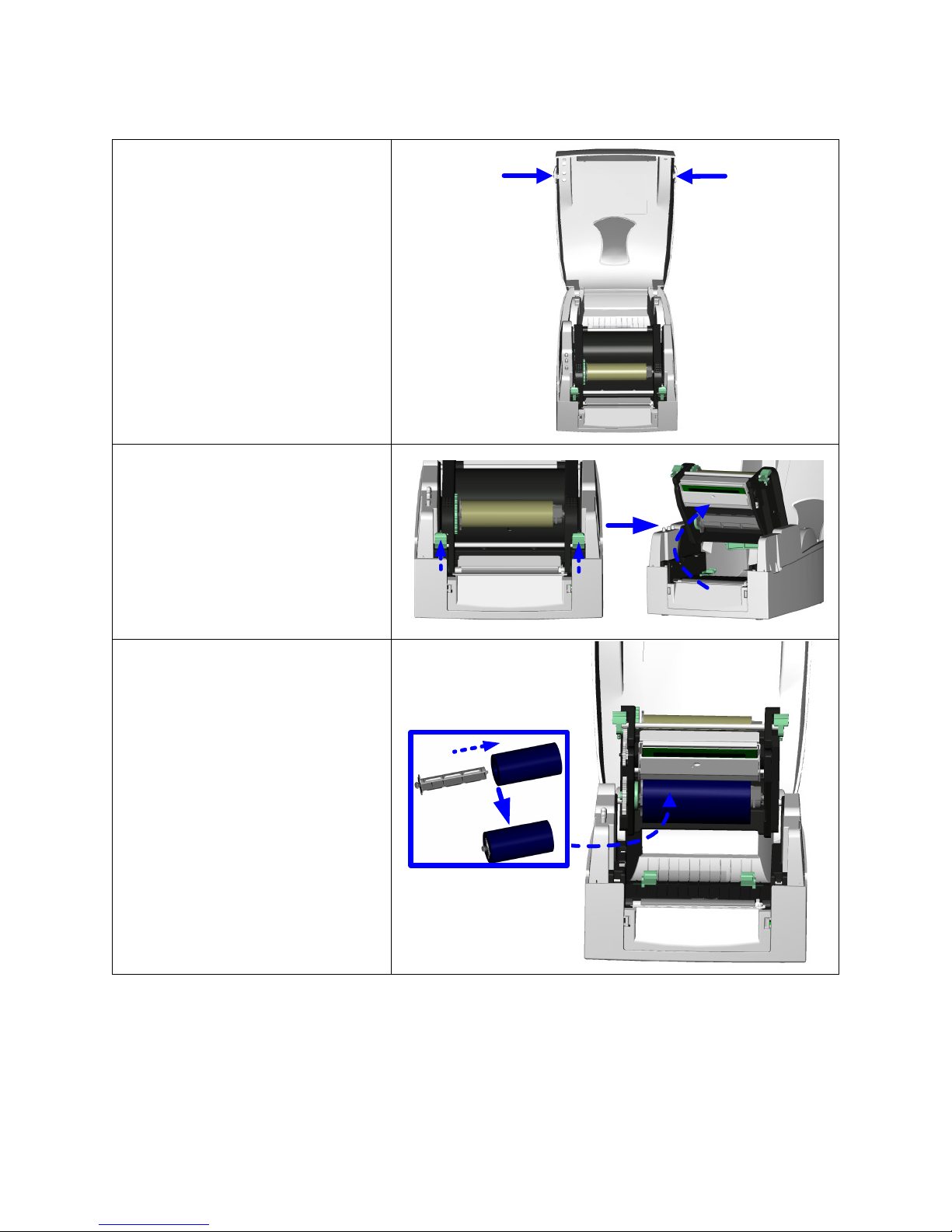
1. Open the Printer’s Top Cover
by pressing the Open Cover
Buttons on both sides.
2. Release the Print Mechanism
by pushing in on the Head
Latches. The Print
Mechanism will now rotate up.
3. Remove the Ribbon Supply
and Ribbon Rewind Shafts.
4. Place the new Ribbon Roll onto
the Ribbon Supply Shaft and
reinstall the Shaft in the
Printer.
13
Page 15
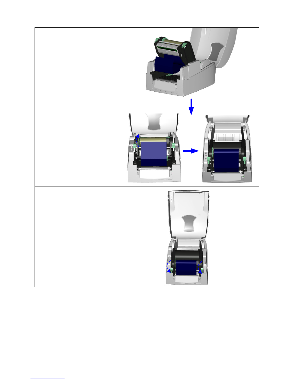
5. Feed the ribbon from the
Ribbon Supply Shaft under
the Printhead.
6. Place the empty ribbon core
onto the Ribbon Rewind Shaft
and reinstall the Shaft in the
Printer.
7. Secure the ribbon to the
empty ribbon roll core with
tape or part of a label and
wrap the ribbon around the
core.
8. Close the Print Mechanism by
firmly pressing down on it.
You will hear a click when the
Print Mechanism has been
secured.
14
Page 16

Label Installation
1. Open the Printer’s Top Cover
by pressing the Open Cover
Buttons on both sides.
2. Place the roll of label stock
onto the Label Roll Core and
place it in the Printer.
3. Release the Print Mechanism
by pushing in on the Head
Latches. The Print
Mechanism will now rotate
up.
4. Feed the label through the
two Label Guides to the
Tear-off Bar.
5. Align the label guides to the
label edge.
6. Close the Print Mechanism by
firmly pressing down on it.
You will hear a click when the
Print Mechanism has been
secured.
15
Page 17
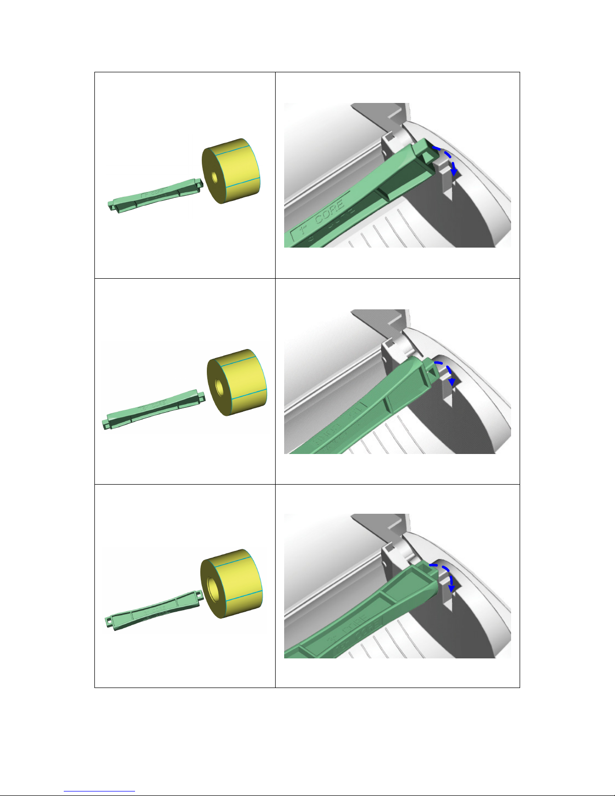
Label Roll Core Installation Instructions
1” Roll Core Installation
1.5” roll core installation
3” roll core installation
16
Page 18
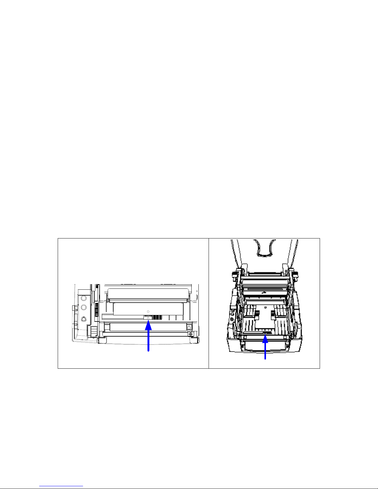
Direct Thermal / Thermal Transfer Mode Switch
Sensor Detection Position
To switch into Direct Thermal (DT) Mode:
1. Turn the Printer Off and press and hold the FEED key.
2. Turn the Printer On while holding down the FEED key.
3. The Printer will beep three times. Continue to hold the FEED key down until the Printer beeps
three more times. Release the FEED key after the third beep.
4. The Printer will print, “NOW IS DIRECT THERMAL (DT MODE)”. This indicates that Printer is now
in DT Mode.
To switch into Thermal Transfer (TT) Mode:
2. Turn the Printer Off and press and hold the FEED key.
3. Turn the Printer On while holding down the FEED key.
4. The Printer will beep three times. Continue to hold the FEED key down until the Printer beeps
four more times. Release the FEED Key after the fourth beep.
5. The Printer will print, "NOW IS THERMAL TRANSFER (TT MODE)". This indicates that Printer is
now in TT Mode.
Card / Hang tags Installation
When installing card tags, the tag hole
must align with the sensor arrow (as
indicated), and then use the Label Guide
to secure the tags.
Tag hole position
Sensor
17
Page 19
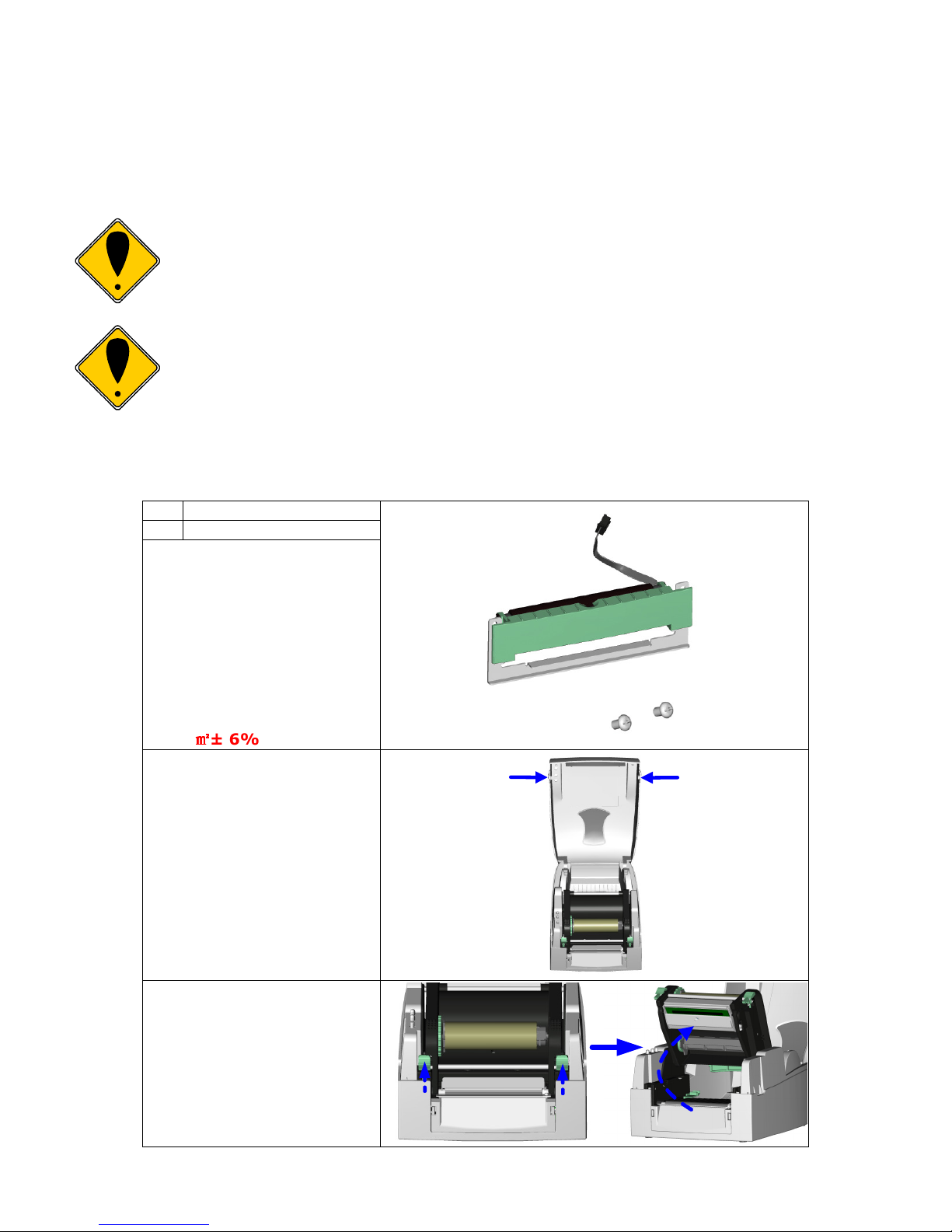
8. Installing the Printer’s Optional Accessories
in on the Head Latches.
The Optional Stripper Sensor Module, Cutter Module, or Compact FLASH Card Slot module with
Real-Time Clock can be easily installed and configured in the field. This section will provide a
component list and installation instructions for these optional accessories.
CAUTION!
Make sure that the Printer’s power switch is in the “O” or “Off” position
before proceeding with the installation.
CAUTION!
Unplug the power cord from the Printer before performing any service
on it. Failure to do so could result in personal injury or damage to the
Printer!
V-Series Stripper Sensor Module Installation Instructions
1 Stripper Sensor Module
2 Screws, Qty. 2
NOTE: The max width
when using the Stripper
Sensor Module is 110mm
NOTE: Recommended
Label liner thickness
when using the Stripper
Sensor Module is 0.06mm
± 10% with basic weight
65g/
㎡㎡㎡㎡
± 6%.
1. Open the Printer’s top
cover by pressing the
Open Cover Buttons on
both sides.
1
2
2. Release the Print
Mechanism by pushing
The Print Mechanism
will now rotate up.
18
Page 20
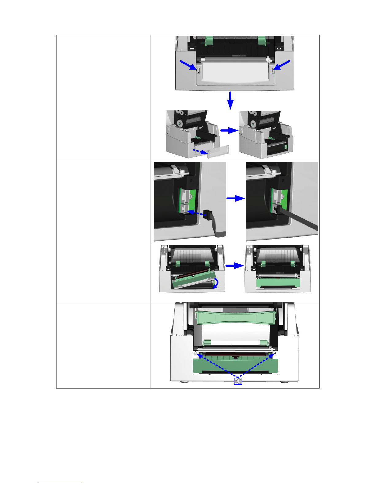
3. The Front Cover Panel
has two tabs, one on
each side. Push these
in to release them and
then remove the Front
Cover Panel as shown.
4. To the right you will see
two sockets. Choose
the socket that has the
same number of pins as
the connector on the
Stripper Sensor
Module. Plug the
connector into that
socket.
5. Position the Stripper
Sensor Module as
shown.
6. Hold the Stripper
Sensor Module while
tightening the screws.
19
Page 21
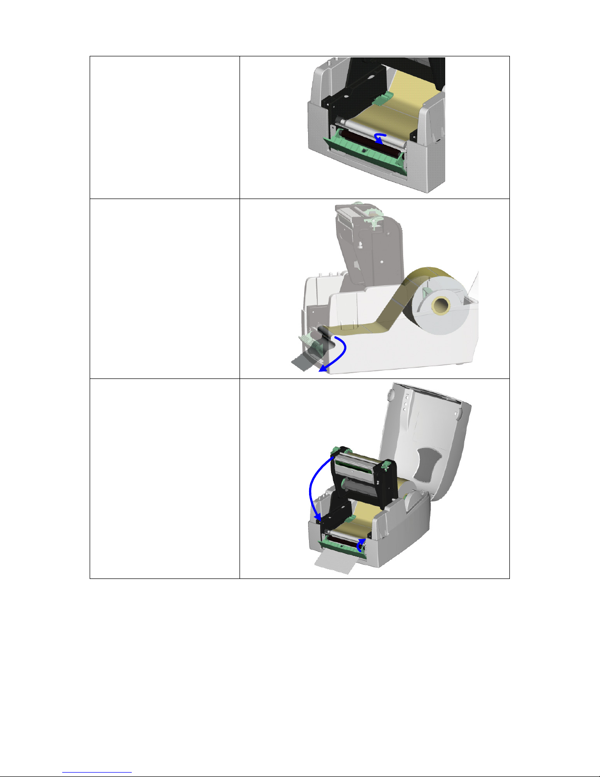
7. Peel off the first label
and feed the liner
through the roller and
peel off bracket.
8. Route the label liner as
shown.
9. Close the Stripper
Sensor Module by
pushing it forward as
shown.
10. Close the Print
Mechanism by firmly
pressing down on it.
You will hear a click
when the Print
Mechanism has been
secured. Then press
the FEED Key.
20
Page 22
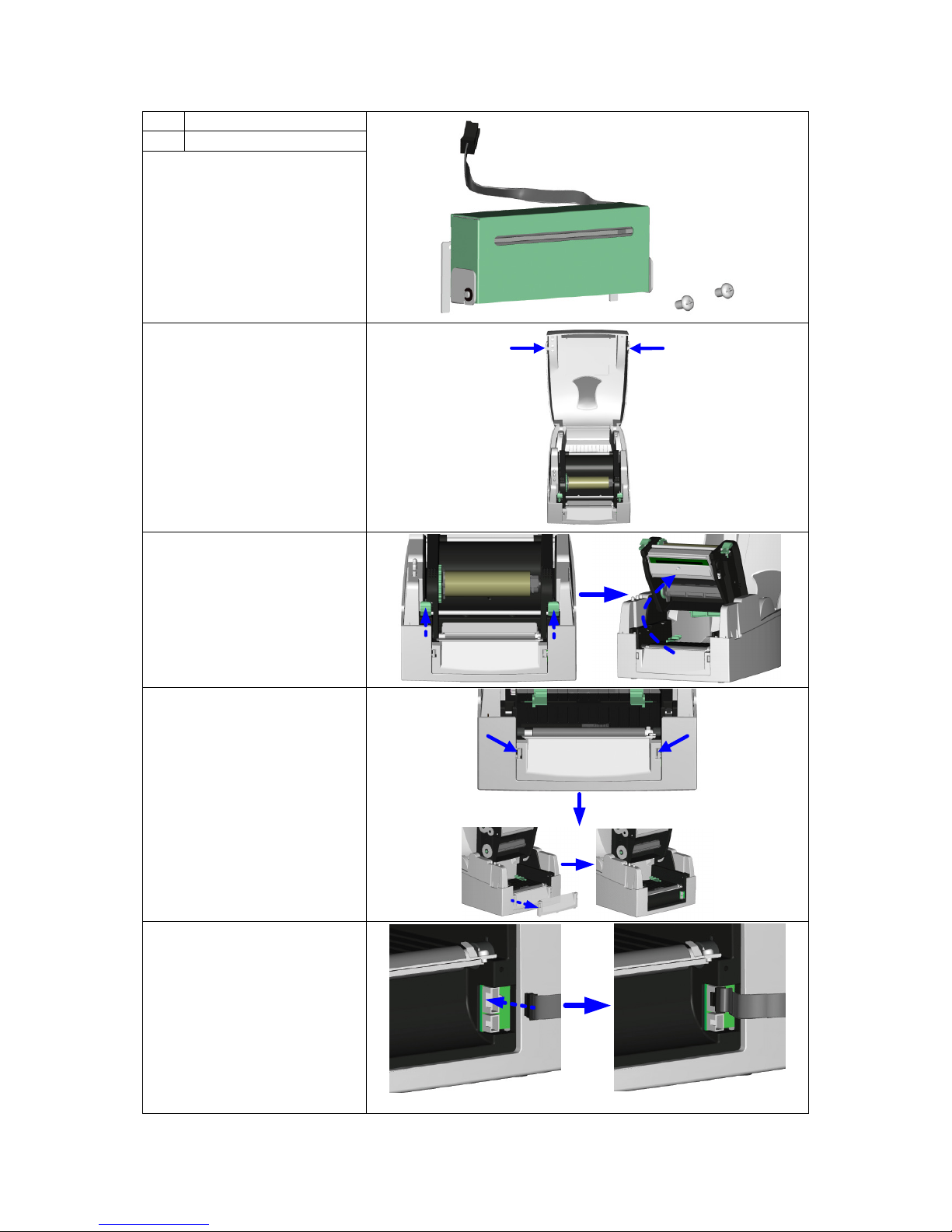
Cutter Module Installation Instructions
1 Cutter Module
2 Screws, Qty. 2
1. Open the Printer’s top
cover by pressing the
Open Cover Buttons on
both sides.
2. Release the Print
Mechanism by pushing
in on the Head
Latches. The Print
Mechanism will now
rotate up.
1
2
3. The Front Cover Panel
has two tabs, one on
each side. Push these
in to release them and
then remove the Front
Cover Panel as shown.
4. To the right you will
see two sockets.
Choose the socket that
has the same number
of pins as the
connector on the
Cutter Module. Plug
the connector into that
socket.
21
Page 23
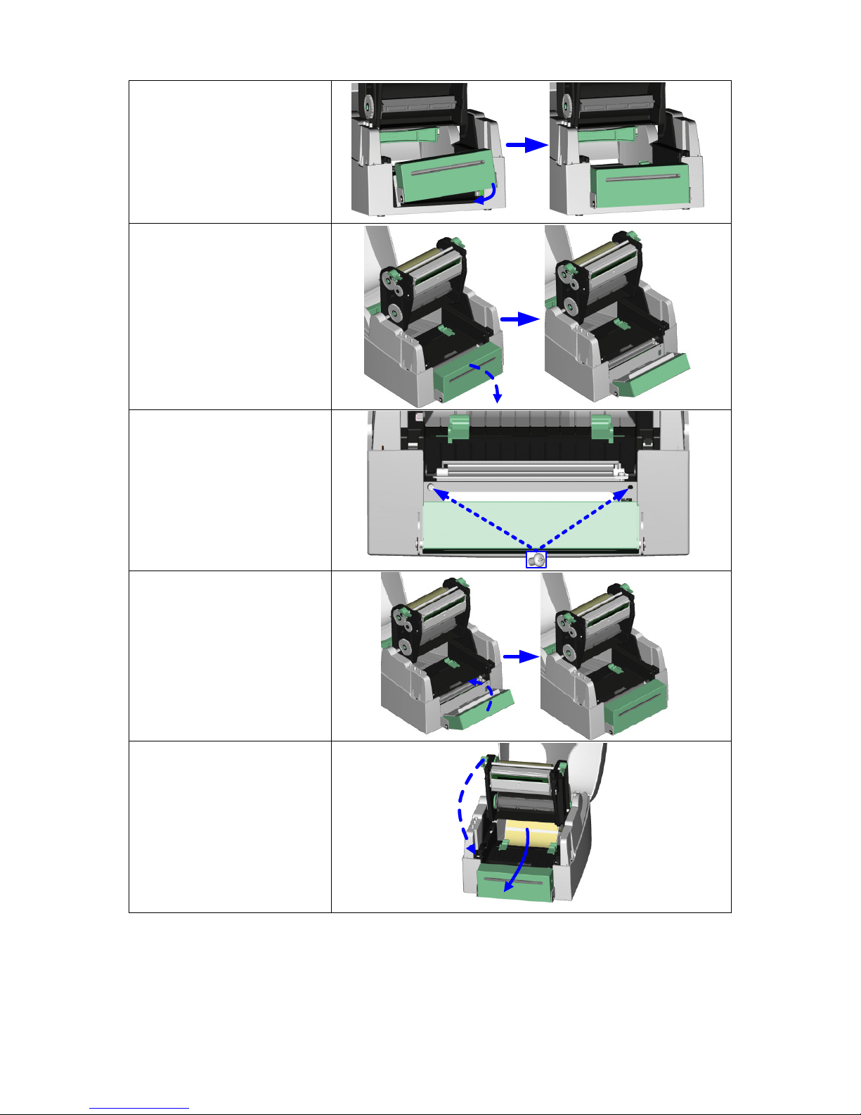
5. Position the Cutter as
shown.
6. Pull up on the Cutter’s
Stainless Cover to
release the Cutter and
then flip the Cutter
Module open.
7. Hold the Cutter Module
while tightening the
screws.
8. Pull on the Cutter’s
Stainless Cover to
release the Cutter and
then rotate the Cutter
back into place.
9. Close the Print
Mechanism by firmly
pressing down on it.
You will hear a click
when the Print
Mechanism has been
secured.
22
Page 24
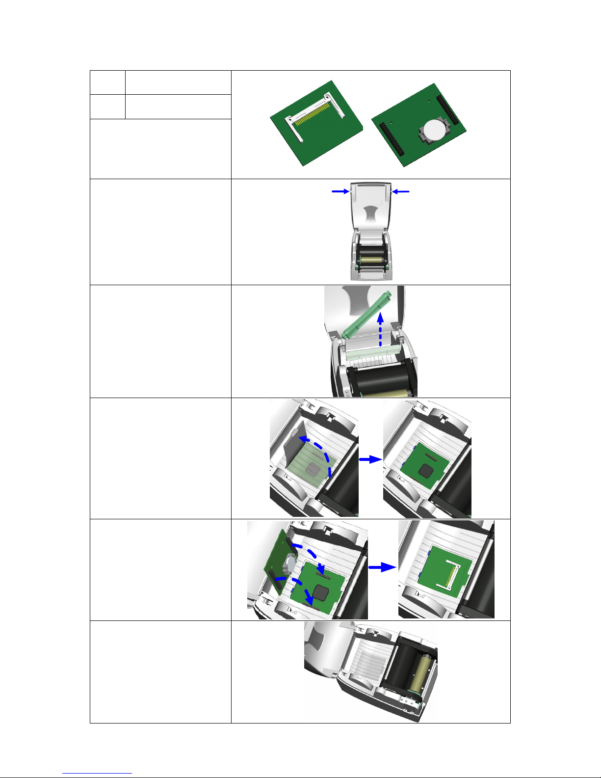
Compact FLASH Card Slot module with Real-Time Clock
Card Slot Module
1
(Front View)
Card Slot Module
2
(Back View)
1. Open the Printer’s top
cover by pressing the
Open Cover Buttons on
both sides.
2. Remove the Label Roll
Core.
1
2
3. Remove the Card Slot
Module Cover.
4. Carefully line up the
connectors and then
plug the Card Slot
Module into the
Mainboard.
5. Replace the Card Slot
Module Cover.
23
Page 25
Appendix A. Communication Interfaces
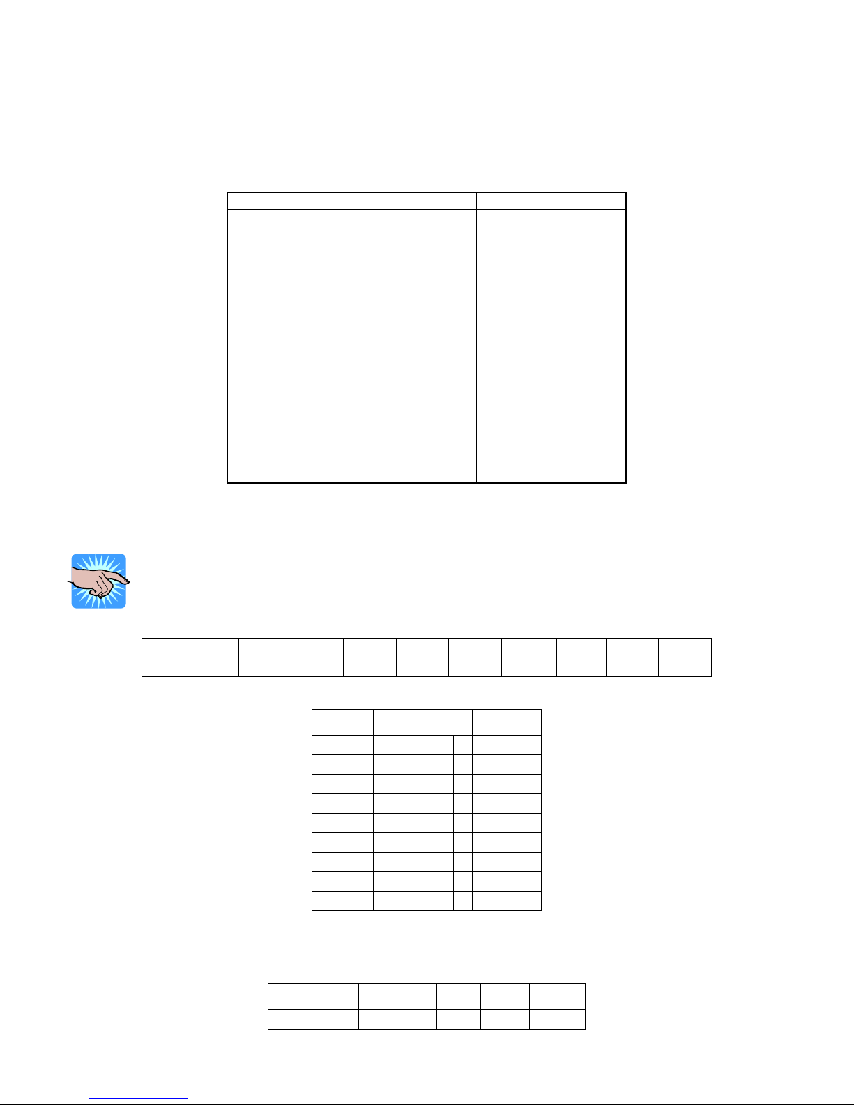
Parallel Interface
The Printers are equipped with a 36-pin Parallel interface connector. Any standard IBM PC compatible
parallel cable can be used to connect to your Printer. In the event of any difficulties, the table listed
below can be used to obtain a suitable cable.
PIN NO. FUNCTION TRANSMITTER
1
2-9
10
11
12
13
14
15
16
17
18
19-30
31
32
33
34-35
36
Serial Interface
The Printers are equipped with a 9-pin SUB-D connector to be used as a Serial interface.
NOTICE!
Make sure that the “COM Port Setup Options” in the Printer’s front panel are
configured the same as the software you will be using with the Printer.
Connector Type: DB9 female, pin assignment is as follows:
PIN NO. 1 2 3 4 5 6 7 8* 9
FUNCTION +5 V TXD RXD N/C GND N/C CTS RTS N/C
Serial interface from PC to Printer
USB Interface
The Printer is equipped with a Type B USB connector that can be connected to any compatible USB port.
PIN NO. 1
FUNCTION USBVCC D- D+ GND
Strobe
Data 0-7
Acknowledge
Busy
Paper Empty
Select
Auto-Linefeed
N/C
Signal Ground
Chassis Ground
+5V DC
Signal Ground
Initialize
Fault
Signal Ground
N/C
Select-in
*Flow Control Line
PC Printer
--- 1 1 +5V
RXD 2 2 TXD
TXD 3 3 RXD
DTR 4 4
GND 5 5 GND
DSR 6 6
RTS 7 7
CTS 8 8
--- 9 9
24
Host / Printer
Host
Printer
Printer
Printer
Printer
Host / Printer
Host
Host / Printer
Printer
Host / Printer
N/C
N/C
CTS
RTS
N/C
2
3 4
Page 26

Appendix B. Error Messages / Troubleshooting
Self Test
The Printer’s Self Test function prints a Test Label that consists of a test pattern and a variety of
information about how the Printer is configured as well as its status.
To perform a Self Test:
1. Turn the Printer Off.
2. Press and hold the FEED key.
3. Turn the Printer On while still holding the FEED key down.
4. Release the FEED key after hearing 3 beeps.
After about 1 second the Printer will print the Test Label. This means the Printer is operating normally.
11
22
33
44
55
66
77
88
99
1100
1111
1122
1133
1144
1155
116
6
V-434Plus : X.XXX
Serial port :96,N,8,1
int-usb sw setting : ext-USB
1 DRAM installed
Image buffer size : 1500K
000 FORM(S) IN MEMORY
000 GRAPHIC (S) IN MEMORY
000 FONT(S) IN MEMORY
000 ASIAN FONT(S) IN MEMORY
000 DATABASE(S) IN MEMORY
2048K BYTES FREE MEMORY
^S4 ^H10 ^R000 ~R200
^W101 ^L76,3
Option : ^D0 ^O0 ^AT
See-through Volt: 4.8 3.4 1.4(3.4)
Code Page: 850
Dump Mode
The Printer’s Dump Mode provides the ability to print the command sequences received by the Printer
instead of executing them. Dump Mode is very useful as a troubleshooting tool when the label settings
and the print results do not match, and can be used to check for errors in data transmission between the
Printer and the PC. Examining the Dump Mode print out will confirm whether or not the correct
commands were received.
To enter Dump Mode:
1. Turn the Printer Off.
2. Press and hold the FEED key.
3. Turn the Printer On while still holding the FEED key down.
4. The Printer will beep three times. Continue to hold the FEED key down; the Printer will beep
again. Continue to hold the FEED key down; the Printer will beep one more time.
5. Release the FEED Key after the last beep. The Printer will print “DUMP MODE BEGIN”. The
Ready LED will glow Green and the Status LED will glow Orange to show that the Printer is in
Dump Mode.
6. Send commands to the Printer and check to see if the commands printed are the same
commands sent by your application.
7. Press the FEED key to exit Dump Mode. The Printer will print “OUT OF DUMP MODE” and beep
to confirm that it is no longer in Dump Mode.
1. Model & Firmware Version
2. Serial port settings
3. USB/Ethernet switch status
4. Number of DRAM installed
5. Image buffer size
6. Number of forms
7. Number of graphics
8. Number of fonts
9. Number of Asian fonts
10. Number of Databases
11. Free memory size
12. Speed, Heat, Reference Point,
Print Direction.
13. Label Width, Label Length, Gap
Length
14. Cutter, Stripper Mode
15. See-through Sensor Status
16. Code Page
25
Page 27

open print head and make
No Ribbon is installed, and the
The Printer is unable to detect
Make sure the movable sensor
ists and the
Printer prints out “Filename is
LED Error Message Descriptions
LEDs Condition or
Message
Print head is open
Entering the
Cooling Process
Out of ribbon or
check Ribbon
Sensor
Out of media or
check media gap
sensor
Check paper
setting
Command is not
recognized
Memory is full Red 2
Filename can not
be found
Filename is
repeated
Ready Status
Red 4 Printhead not firmly in place.
Red
(Flash)
Red 3
Red 2
Red 2 Improper paper feed.
Red 2
Red 2
Red 2
Red
(Flash)
NOTICE!
The Printer repeats all warning beeps. For example when the Printer’s
Printhead Mechanism is opened, the Printer will beep four times, pause, and
then beep four more times.
Beeps Description Solution
None
Re-
sure it closes tightly.
Printhead temperature is too
high.
Printer shows error message.
The ribbon is used up or
Ribbon Supply Shaft is not
moving.
label stock.
The label stock is used up. Replace with new label roll.
Wrong command; the Printer
prints out “Command is not
recognized”.
Memory is full; the Printer
prints out “Memory full”.
Can’t find the file; the Printer
prints out “Filename can not
be found”.
File name is repeated; the
repeated”.
Printer will go back into
Standby Mode after cooling.
Make sure the Printer is in
Direct Thermal mode.
Replace with new ribbon roll.
is at the correct position. If
the sensor is still unable to
detect labels then go through
the Auto Sensing steps again.
Possible causes:
1. Media falling into the gap
behind the platen roller.
2. Can’t find the label gap/
black mark.
3. Black mark paper out.
Check Printer commands,
possible errors or missing
parameters.
Delete unnecessary data in
the memory or add the
optional memory expansion
module.
Use “~X4” command to print
out all the files and check
whether the file ex
name is correct.
Change the file name and
download again.
26
Page 28
” to perform a Test Print and check
The Cutter did not cut the label
Check that label is greater than 35mm (1.38”) high so it can
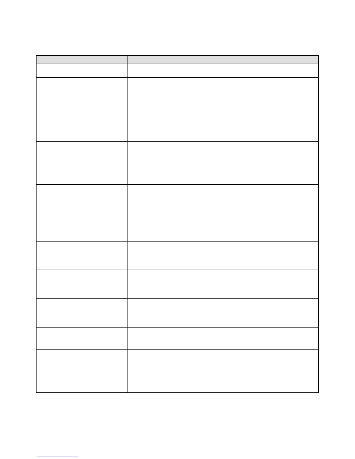
Problems and Recommended Solutions
Problem Recommended Solution
LED does not light after
switching the Printer on
LED turns red (power/status)
after printing stops
Printing started but nothing
was printed on the label
The labels jammed when
printing
Only part of the label was
printed
Part of the label was not
printed completely
Printout not in desired position
Labels are skipped while
printing
Smudged or blurry printout
The Cutter did not cut straight
successfully
When using the Cutter the
labels could not feed or
abnormal cutting occurs
The Stripper Sensor is not
functioning correctly
Check the power cord
Check for software setting or program command errors
Check if labels or ribbon is out and replace with suitable
labels or ribbon
Check if label stock is jammed
Check if Printhead Mechanism is closed (Printhead not
positioned correctly)
Check if sensor is blocked by paper/label
If cutter is installed check that it is working and working
properly
Check that the ribbon is installed with the inked side facing
the label media.
Select the correct Printer driver
Select the correct label stock and print mode
Clear the label jam and check that the Printhead is clean
Check if label or ribbon is stuck on the Printhead
Check if application software has errors
Check if start position setting has errors
Check if ribbon has wrinkles
Check if Ribbon Supply Shaft is creating friction with the
platen roller. If the platen roller needs to be replaced,
please contact your Reseller for more information.
Check if power supply is within the voltage range
Check if Printhead is dirty
Use internal command “~T
if the Printhead can print across its entire width
Check the media quality
Check if sensor is covered by paper or is dirty
Check if liner is suitable for use, please contact Reseller for
more information
Check if label roll edge is aligned with Label Width Guide
Check if error occurs on label height setting
Check if the sensor is covered by paper or is dirty
Check print darkness setting
Check if Printhead is dirty
Check if label stock is installed correctly
Check if the label thickness exceeds 0.16mm (.006”)
Check if Cutter is installed properly
Check if Paper Feed Rods are sticky
clear the Cutter
Check if Stripper Sensor is covered with dust
Check if labels are installed properly
27
Page 29
Appendix C. Maintenance and Adjustment
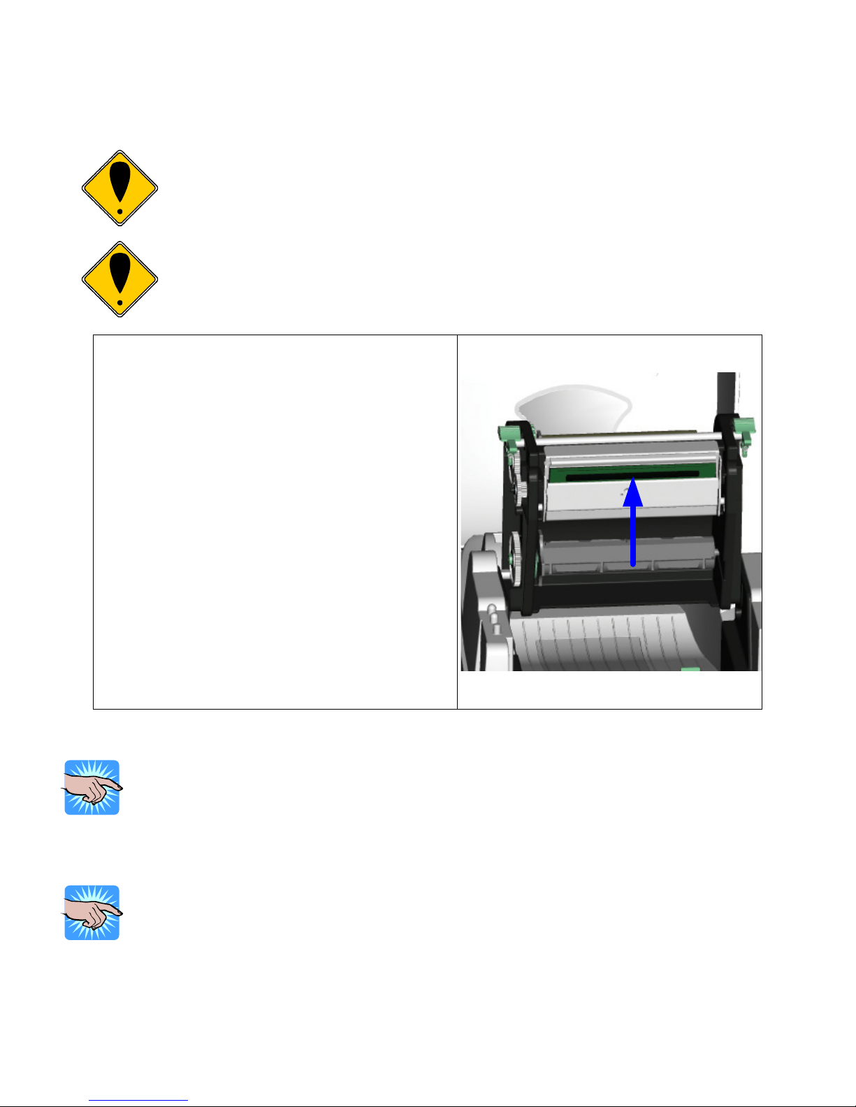
Printing labels will cause dirt such as paper dust,
particles of ink and label adhesive to accumulate on
rmal Printhead. This can cause poor print
on the Head Latches. The Print Mechanism
Clean the Printhead surface (see blue arrow)
with a special cleaning pen or a cotton swab
Cleaning the Thermal Printhead
CAUTION!
The Printhead is the Most Fragile part of your Printer. Do NOT use sharp
or hard objects to clean the Printhead. Do NOT touch the glass surface
of the Printhead with your hand.
CAUTION!
During the print process the Printhead will become hot. Do NOT
attempt to clean the Printhead until it has had time to cool.
the The
quality and incomplete printouts.
When this happens the Printhead must be cleaned:
1. Turn the Printer Off.
2. Open the top cover.
3. Release the Print Mechanism by pushing in
will now rotate up.
4. Remove the ribbon from the Printer.
5.
soaked in Isopropyl Alcohol.
6. Allow the Printhead to dry for 2-3 minutes
before turning the Printer back on.
NOTICE!
To help keep the Printhead clean the top cover of the Printer should be
closed when printing. To ensure print quality and prolong Printhead life, do
NOT use dusty or dirty print media in the Printer.
NOTICE!
Recommended cleaning intervals for the Thermal Printhead:
Direct Thermal Printing – Each time the label roll is changed
Thermal Transfer Printing – Each time the ribbon is changed
28
Page 30
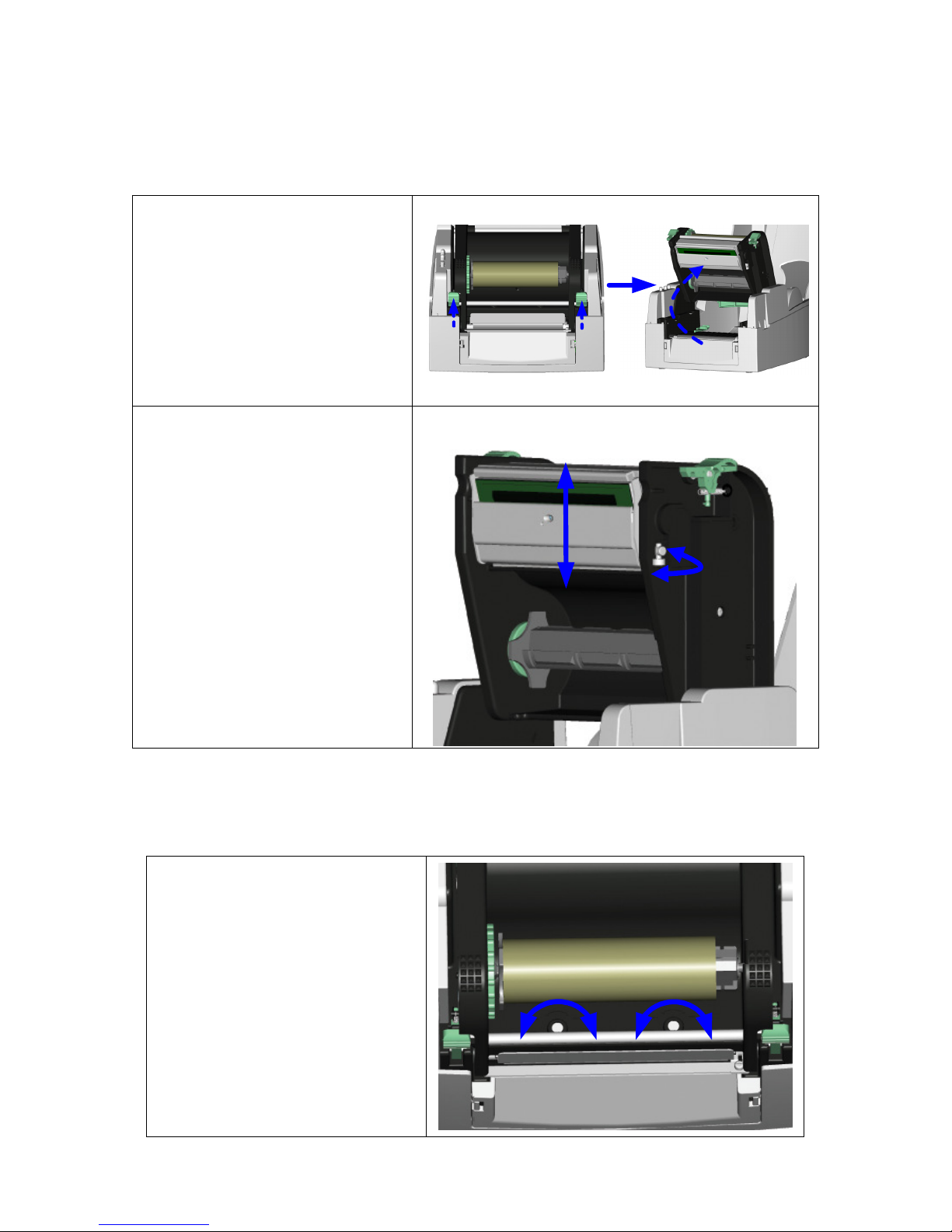
Thermal Printhead Print Line Adjustment
When printing on stiff or thick paper, the Print Line needs to be moved forward (paper feed direction) in
order to achieve better print quality.
1. Release the Print Mechanism
by pushing in on the Head
Latches. The Print
Mechanism will now rotate up.
2. Turning the Print Line
Adjustment counterclockwise
(as arrow 1 shows) will move
the Printhead in the direction
of arrow A.
3. Turning the Print Line
Adjustment clockwise (as
arrow 2 shows) will move the
Printhead in the direction of
arrow B.
A
1111
2222
B
Thermal Printhead Spring Box Pressure Adjustment
If one side of the printed labels is not being printed clearly, or if ribbon wrinkles occur, then adjust the
Thermal Printhead Spring Box Pressure to cure the problem.
1. Open the Top Cover.
2. Remove the Thermal Transfer
Ribbon.
3. Turn the Printhead Adjustment
Screws to increase or decrease
the Printhead pressure.
++++
29
----
++++
----
Page 31
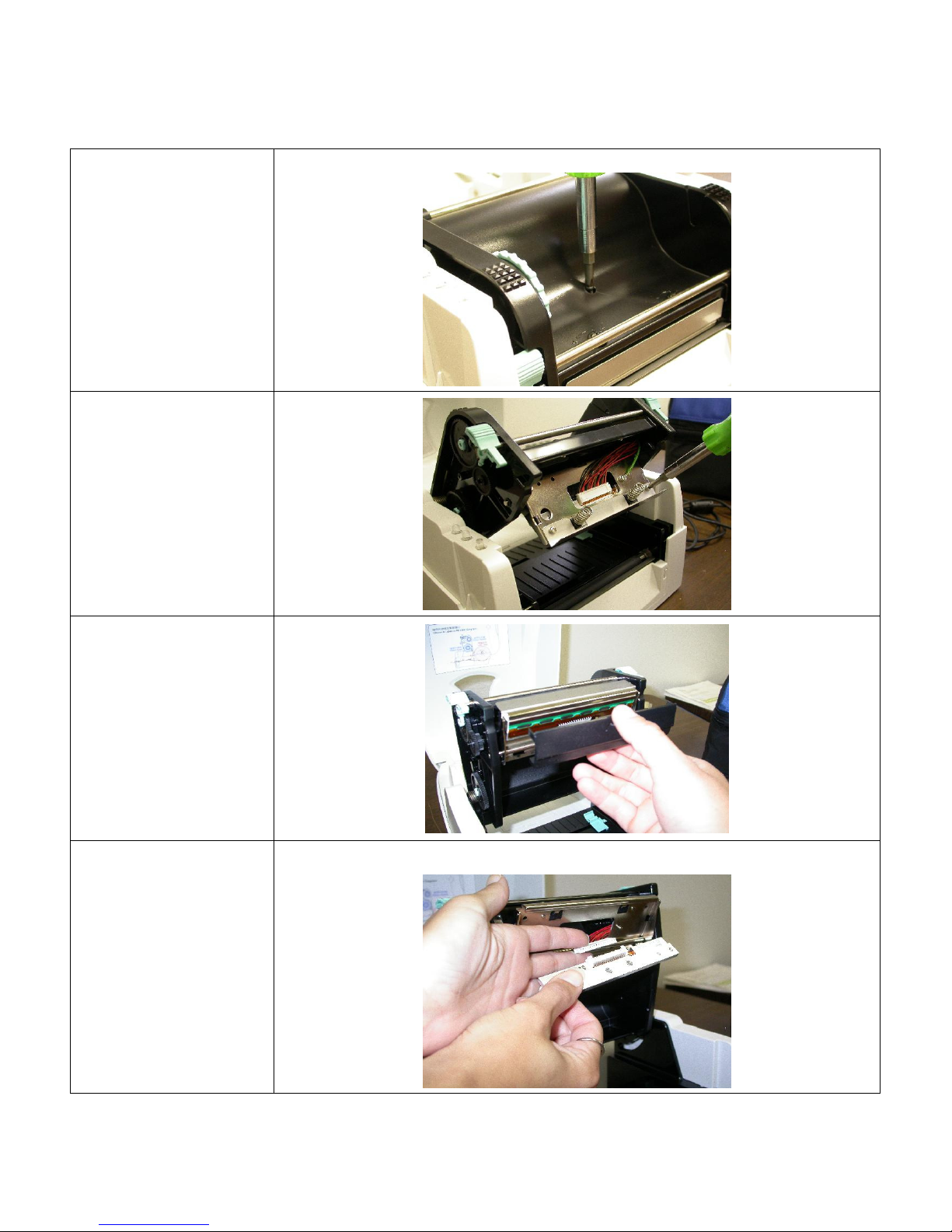
Thermal Printhead Replacement
1. Switch the power to
the Printer off and
unplug the Printer.
2. Open the Printhead
and remove the
media from the
Printer.
3. Remove the
Printhead Carriage
Screw as shown.
4. Once the Printhead
Carriage Screw is
removed, the
Printhead Carriage
will drop down and
provide access to
the Printhead
Screws.
5. Remove the two
Printhead Screws
6. Remove the plastic
Printhead Guard
from beneath the
Printhead and the
Printhead will hang
from the Carriage
by the Printhead
Cable
7. Gently unplug the
Printhead Cable
from the Printhead.
8. Reverse these steps
to re-install the
Printhead.
30
Page 32
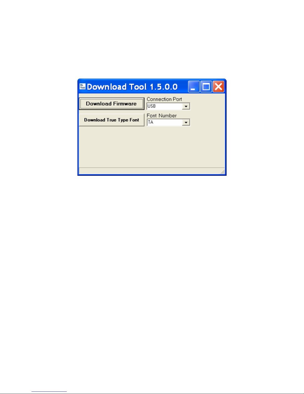
Upgrading the Printer’s Firmware
The Printer’s firmware can be upgraded in the field by performing the following procedure:
1. Connect the Printer to a computer.
2. Unzip the firmware files and save them to a directory on your computer.
3. Start the Download Tool program by double clicking on DownloadTool.exe .
4. Select the port that is being used to communicate with the Printer and click the “Download
Firmware” button. If downloading via the serial port the baud rate MUST be set to 115200 in the
Printer.
5. This will bring up a Browse Window displaying the firmware (.bin) files that can to be loaded to
the Printer. Select the appropriate firmware file and click “Open”.
6. After the “Open” button is clicked, the firmware download process will start immediately. A blue
progress bar will pop up to display the progress of download.
7. When the progress bar reaches “100%”, the firmware download is complete. As the download
finishes, the Ribbon and Media light will alternately flash slowly and then rapidly.
8. The Printer will now reset, please wait for Printer to complete the reset procedure. The Printer will
return to “Ready to print” status after the reset.
9. The new firmware version will be displayed on the Printer’s LCD. This confirms that the
firmware has been updated.
31
Page 33
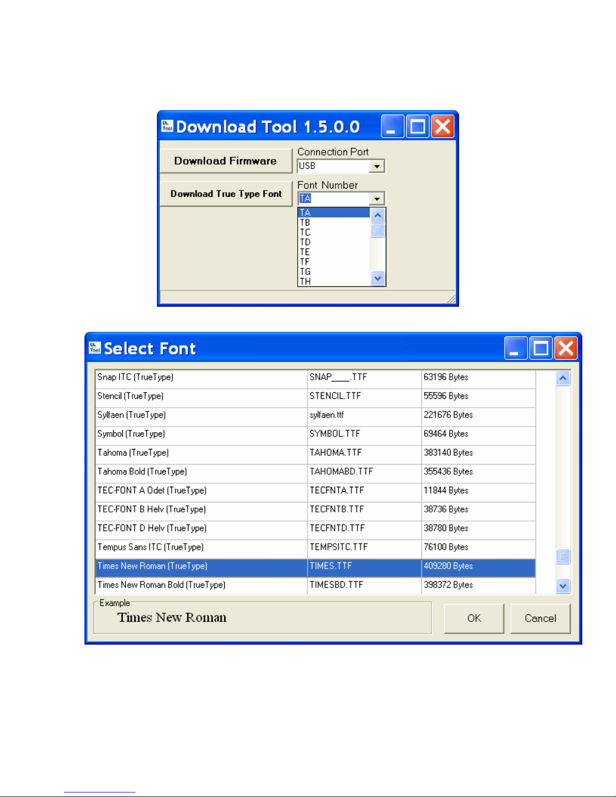
Downloading True Type Fonts to the Printer’s Flash Memory
1. Start the Download Tool program by double clicking on DownloadTool.exe .
2. Select a ‘Font Number’ that will be used to identify the downloaded True Type Font.
3. Click the “Download True Type Font” button, the program would show a list of True Type Fonts
that are available for download. Select a True Type Font and click “OK”.
4. After the “Open” button is clicked, the download process will start immediately. A blue progress
bar will pop up to display the progress of download.
5. When the progress bar reaches “100%”, the True Type Font download is complete and the True
Type Font is stored in the Printer’s Flash memory.
32
Page 34
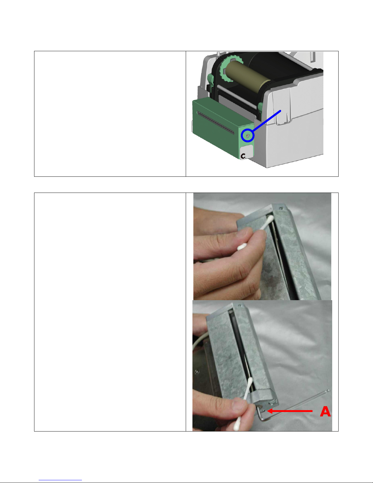
If the Cutter jams or malfunctions turn the
There is a hole (marked “A”) on each side
of the Cutter. Insert a 3mm hex key into
than 35mm (1.38”) in height in order for them to
There is a hole (marked “A”) on each side
of the Cutter. Insert a 3mm hex key into
the Printer back On. The cutter blade will
Clearing Cutter Jams
1.
Printer Off.
2.
one of these holes and turn the cutter
blade clockwise.
3. After the problem is corrected, turn the
Printer back On and the cutter blade will
go back to its original position.
Note: It is recommended to use labels greater
clear the Cutter.
A
Cleaning Adhesive from the Cutter Blade
When using adhesive labels, the cutter may
malfunction due to a build up of adhesive on
the blade. When this happens it will be
necessary to clean the Cutter Blade:
1. Turn the Printer Off.
2. Remove the Cutter assembly from the
Printer.
3. Wet a cotton swab in Isopropyl Alcohol
and use it to remove any build-ups of
adhesive.
4.
one of these holes and turn the cutter
blade clockwise to allow access to the
entire length of the blade.
5. Allow the cutter to dry for 10 minutes.
6. Re-install the Cutter assembly and turn
go back to its original position.
33
 Loading...