

Page 1
T-4210/T
-4307/T-4604
Users Manual
Date:
02-26-2015
Page 2

CONTENTS
1
Barcode Printer
1
1.1
1.2
Box Contents
Getting to Know Your Printer
1
2
2
Printer Setup
4
2.1
2.2
2.3
2.4
2.5
Loading Labels
Loading Ribbon
Connecting the Printer to the Host Computer
EASYLABEL Start installation
4
8
10
3
Printer Setting and Control
16
3.1
3.2
3.3
3.4
3.5
3.6
Operation Panel
LCD Interface Introduction
LCD Interface Functions
Label Calibration and Self-Test
Error Alerts
USB Host
16
17
21
27
29
31
4
NetSetting for Ethernet
33
4.1
4.2
Installing the NetSetting Software
NetSetting Interface
33
34
5
Accessories
41
5.1
5.2
5.3
Preparation
Installing the Cutter
Ribbon Removal from the Optional Core-free Ribbon Hub
41
42
6
Maintenance and Adjustment
49
6.1
6.2
6.3
6.4
6.5
6.6
6.7
6.8
Removing / installing the print head module
Adjusting the print line
Adjusting ribbon tension
Cleaning the thermal print head
Print head balance and tension adjustment
Ribbon shield adjustment
Cleaning the cutter
Troubleshooting
49
50
51
52
53
54
55
56
Appendix
your Computer
Windows Driver installation
14
11
45
57
Product Specifications
Interface Specifications
57
58
5.4
5.5
47
48
Installing the WiFi Interface Module
Installing the Bluetooth Interface Module
Page 3

FCC COMPLIANCE STATEMENT
FOR AMERICAN USERS
This equipment has been tested and found to comply with the limits for a CLASS A digital device,
pursuant to Part 15 of the FCC Rules. These limits are designed to provide reasonable protection
against harmful interference when the equipment is operated in a commercial environment. This
equipment generates, uses, and can radiate radio frequency energy and, if not installed and used
in accordance with the instructions, may cause harmful interference to radio communications.
Operation of this equipment in a residential area is likely to cause harmful interference in which case
the user will be required to correct the interference at their own expense.
THE T-SERIES PRINTER
TO WHICH THIS DECLARATION RELATES
IS IN CONFORMITY WITH THE FOLLOWING STANDARDS
European Standard EN 55022:2010/AC:2011 Class A,EN 61000-3-2:2006/A1:2009 and /a2:2009, EN 61000-3-3:2008 and
EN55024:2010(IEC 61000-4-2:2008, IEC 61000-4-3:2006/A1:2007/A2:2010, IEC 61000-4-4:2004/A1:2010, IEC 61000-4-5:2005,
IEC 61000-4-6:2008, IEC 61000-4-8:2009, IEC 61000-4-11:2004). CFR 47, Part 15
WARNING
This is a Class A product. In a domestic environment this product may cause radio interference
in which case the user may be required to correct the interference at their own expense.
㭋ḡ&ODVV$Ẏ⒨Ə✏䔆㴢䎖⡪ḔƏ富Ẏ⒨⏖僤怇ㇷ㗇亦䔜⹙㉗Ə✏忀䦴ガ↜Ə⏖僤曧奨䔏㈞⯠⅝⹙㉗憮⎽⇮⮅⏖堳
䙫㎑㖤˛
Page 4

SAFETY INSTRUCTIONS
During the print process the Printhead will become hot. Do NOT attempt to clean the
Printhead until it has had time to cool.
The Printhead is the most fragile part of your Printer. Do NOT use sharp or hard objects to
clean the Printhead. Do NOT touch the glass surface of the Printhead with your hand.
This Printer is built exclusively to print labels, tickets and tags, continuous paper, etc. Only
use media that is recommended for a direct thermal or thermal transfer Printer.
The Printer is configured for input voltages of 110 to 240 V. Connect only to a power outlet
with a grounded contact. Always ensure the Printer is switched OFF before connecting the
power cord to an electrical outlet.
Do not expose the Printer to moisture or operate it in wet or damp areas.
The Printer will operate with the cover open if necessary. This is not recommended, as the
Printer’s moving or rotating parts can cause injury. Keep long hair, jewelry and loose
clothing away from any moving parts.
Remove the power cord from the rear of the Printer when disconnecting or attaching
accessories such as rewind units, cutters, etc.
**** There is a Danger of explosion if the battery is replaced incorrectly.
**
** Dispose of used batteries according to the manufacturer’s instructions.
***
* Only replace the battery with an equivalent type.
Specifications are subject to change without notice.
Caution
This printer is equipped with a button cell lithium battery. This battery is inside the left side cover
on the main circuit board.
Page 5
1 Barcode Printer
1.1 Box Contents
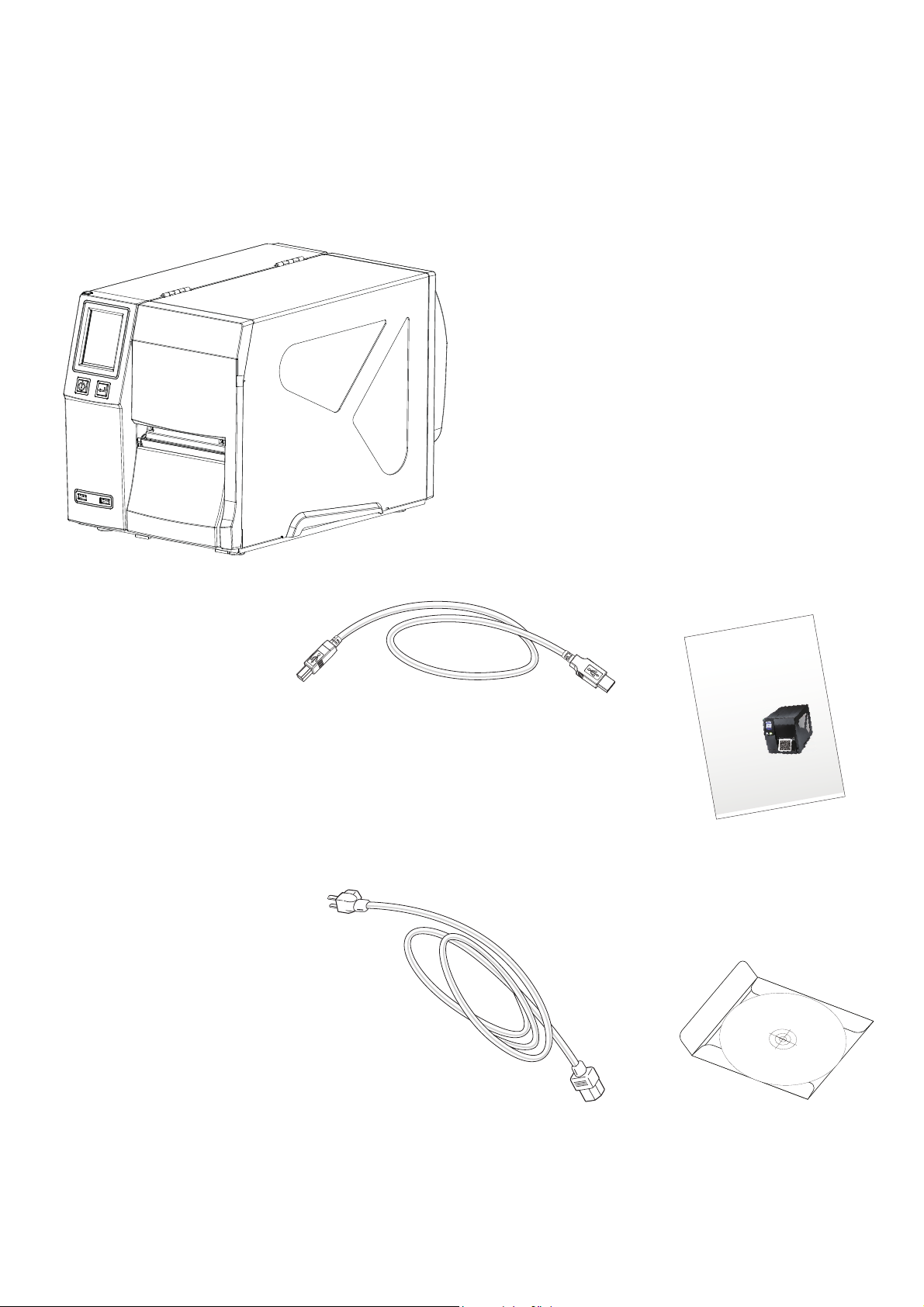
Please check that all of the following items are included with your printer.
T-4210 / T-4307/ T-4604 Printer
=
CD
Including EASYLABEL Start software
and user’s manual.
=
=
4XLFN*XLGH
T-4210 / T-4307 / T-4604 Series
USB Cable
=
Power Cord
=
1
Page 6
Front View
=
1 Barcode Printer
1.2 Getting to Know Your Printer
Rear View
=
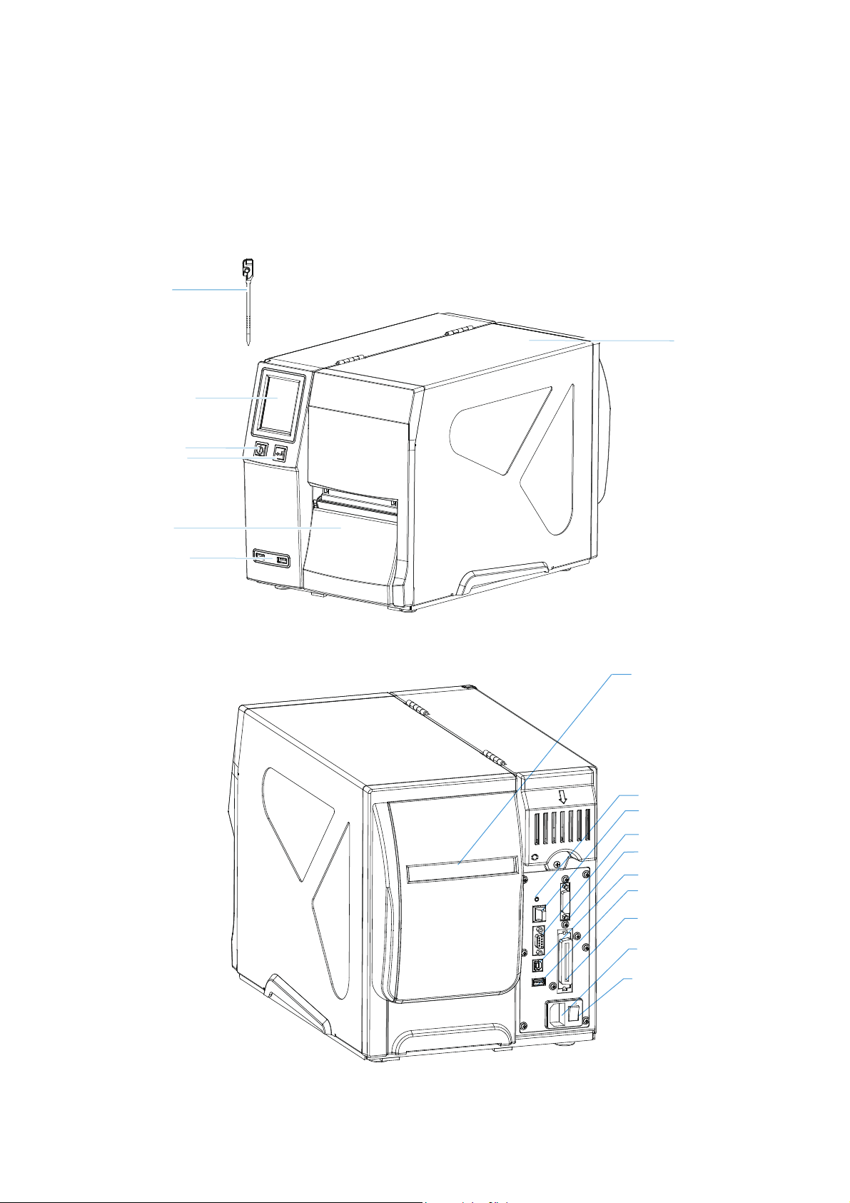
Stylus
Touch Panel
POWER Button
FEED Button
Lower Cover Plate
USB Host
Printer Cover
Viewing Window
Fan-Fold Label Slot
Calibration button
Ethernet port
Serial port (DB-9)
Applicator Interface(OPTIONAL)
USB Port
USB Host
Parallel port(OPTIONAL)
Power jack
On/Off switch
2
Page 7
1 Barcode Printer
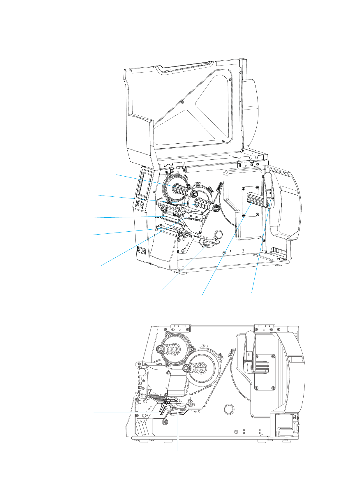
Ribbon Rewind Hub
Ribbon Supply Hub
Print Mechanism
Platen Roller
Print Head
Release Lever
Label Guide
Label Roll Hanger
Label Roll Guide
Adjustable Sensor
Label Guide
3
Page 8
This printer supports the following printing methods:
Thermal Transfer Printing (TTP)ƝRequires a ribbon for transferring the printed image to the labels.
Direct Thermal Printing (DTP)Ɲ8VHV7KHUPDO3DSHUDQGGoes not require a ribbon.
Verify which printing method you are using and modify the settings in the printer driver,
printer menu, and/or software.
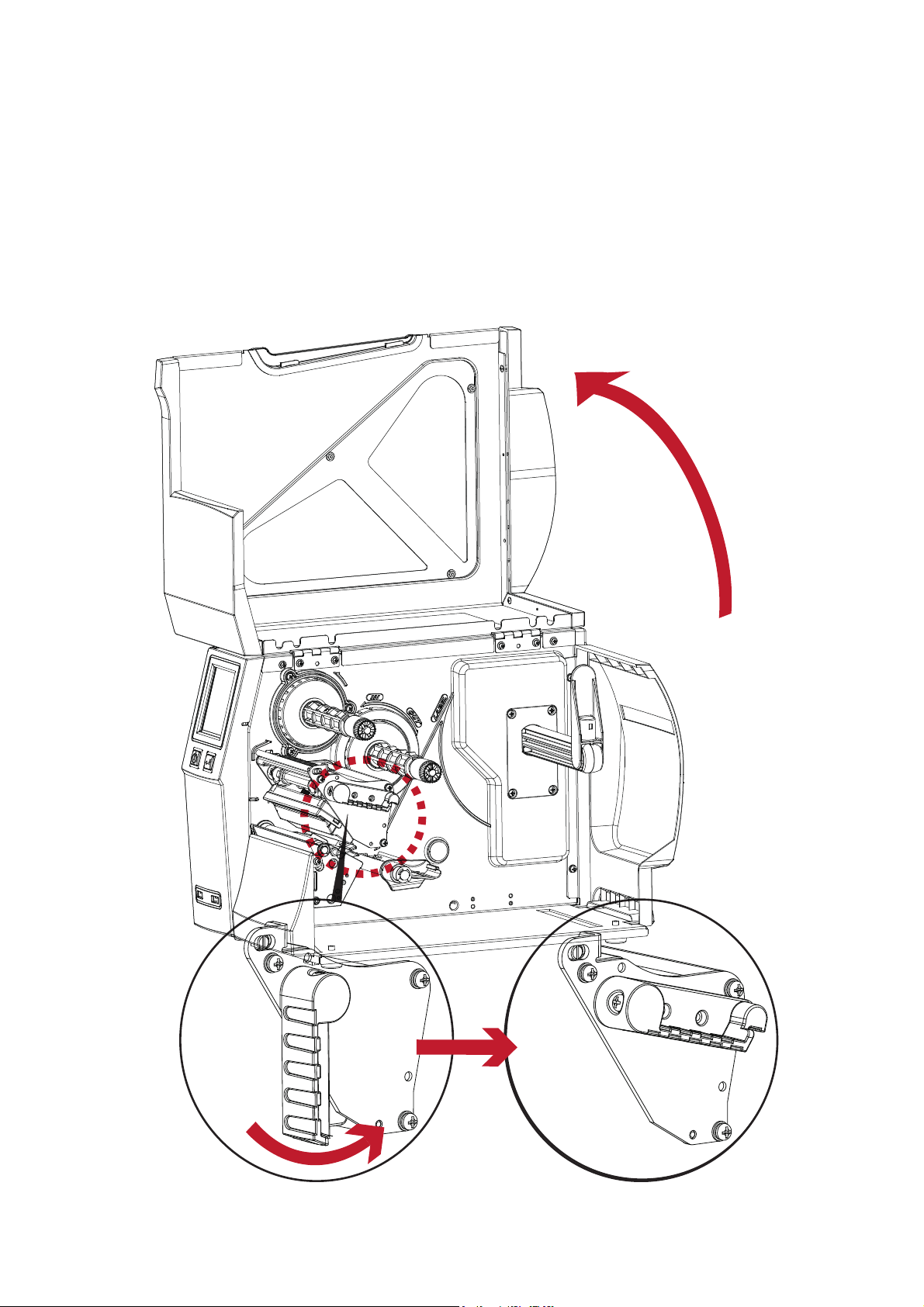
Rotate the Print Head Release Lever counterclockwise as shown
2.1 Loading Labels
2 Printer Setup
Place the printer on a flat surface
and open the top cover
4
Page 9
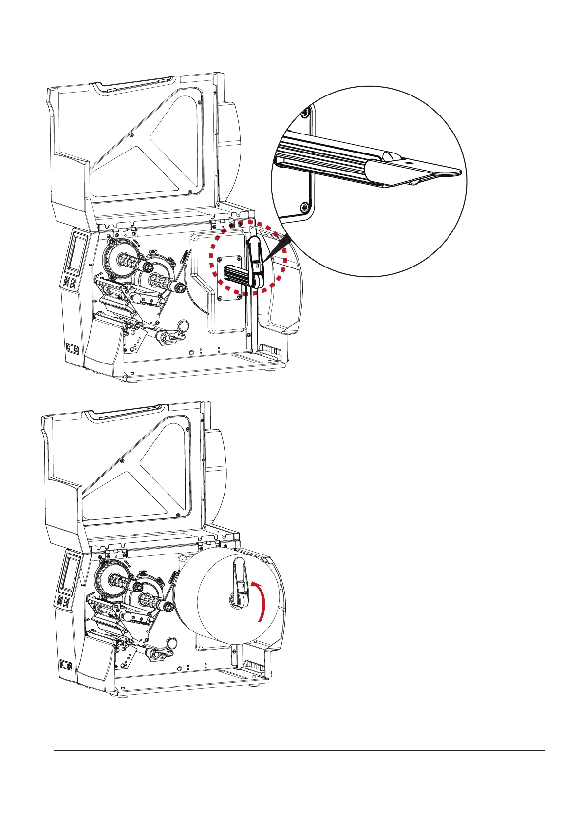
Slide the label roll guide out and fold it down
Place the label roll on the label supply hub
until it contacts the printer housing.
(Do not apply too much pressure to avoid
damaging the label stock.)
* :KHQPRYLQJWKHODEHOUROOJXLGHKROGLWRQO\E\WKHHQGWKDWLVDWWDFKHGWRWKHEUDFNHWQRWE\LWVWRS
1RWH
2 Printer Setup
5
Page 10
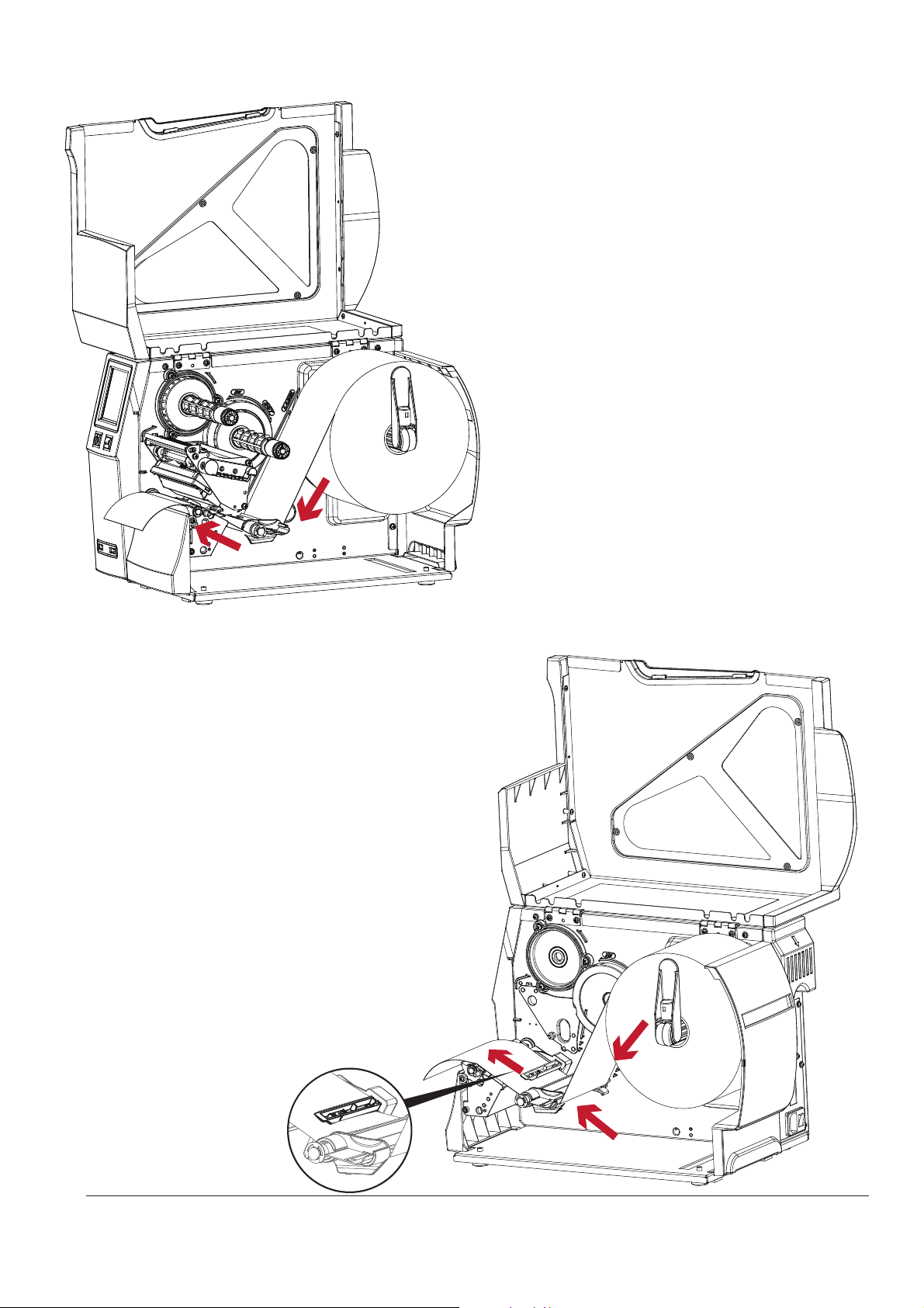
Feed the label stock through the printer as indicated by the red arrows
Feed the label stock through the
Adjustable Sensor and up to the tear-off plate.
* Remember to change the position of the movable sensor and align it to the gap, black mark, or tag hole in the media.
1RWH
2 Printer Setup
6
Page 11
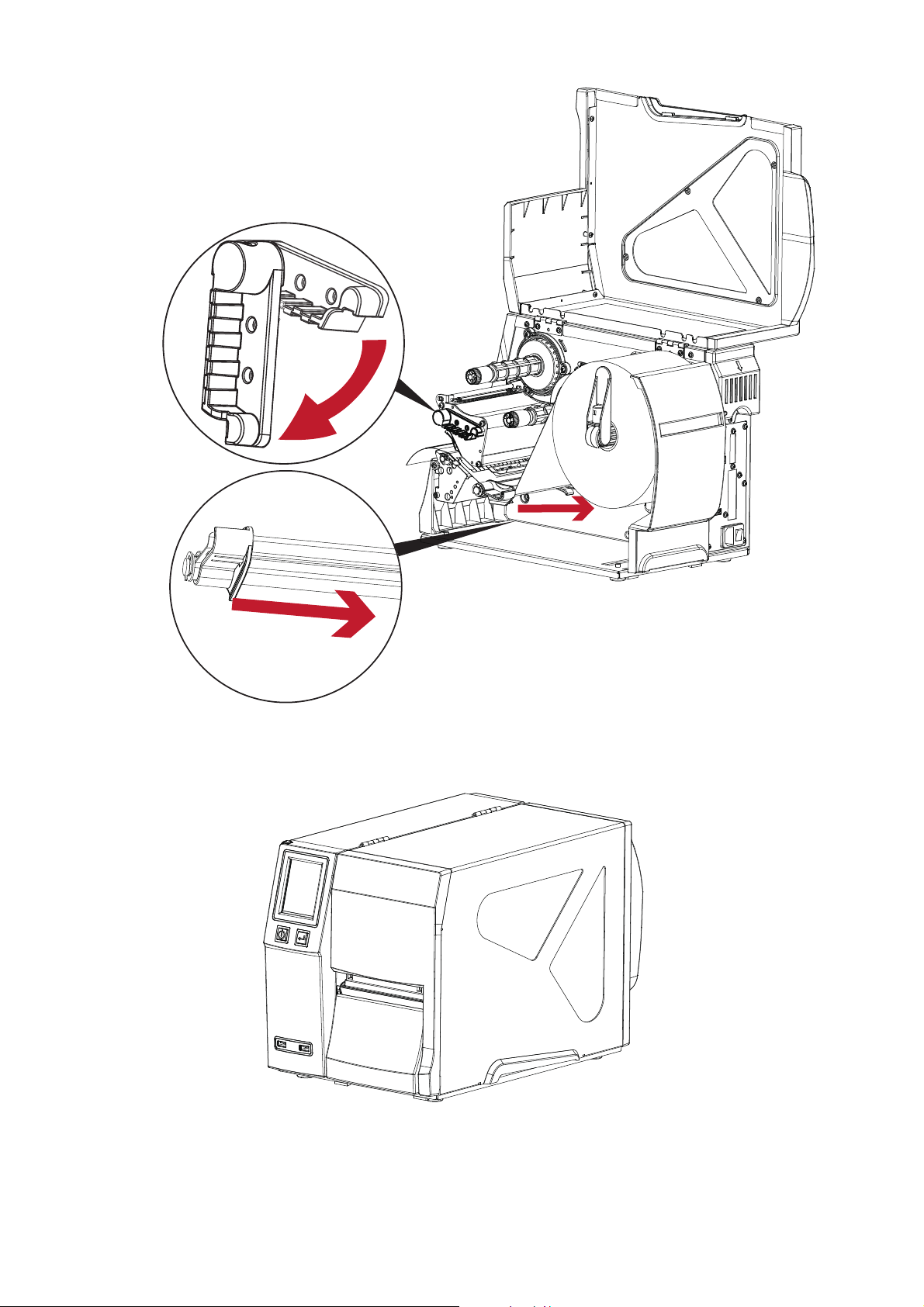
1. The labels pass between the wall of the printer housing
and the adjustable paper guide.
2. Return the Print Head Release Lever to its original position.
Then close the printer cover.
2 Printer Setup
7
1. The labels pass between the wall of the printer housing
and the adjustable paper guide.
1
2
1
Page 12
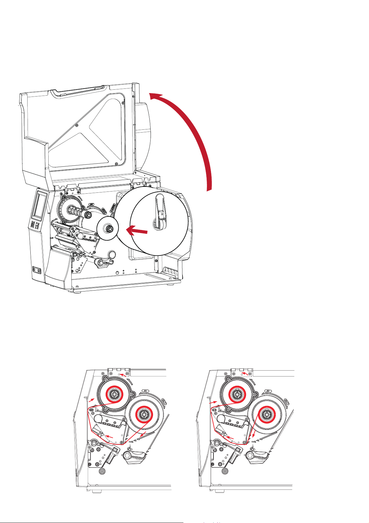
Place the printer on a flat surface
and open the top cover
Place a new ribbon on the ribbon supply hub.
The two illustrations below show you how to route the ribbon depending on the ribbon type (ink side in or out).
Ink side out Ink side in
2 Printer Setup
2.2 Loading Ribbon
Loading Ribbon
8
Page 13
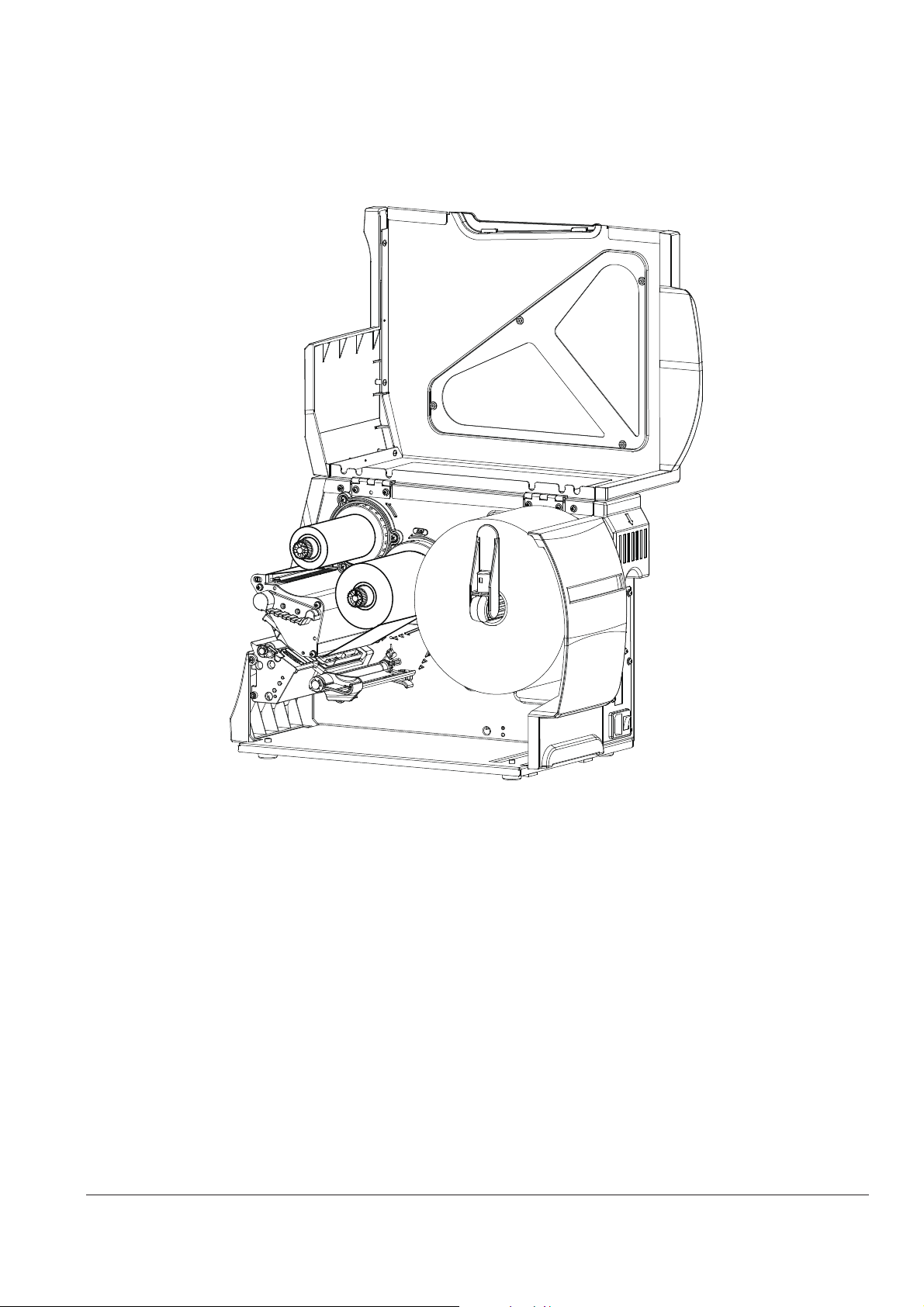
* Do not feed the ribbon under the Adjustable Label Sensor.
1RWH
2 Printer Setup
Feed the ribbon under the print head and back up on the other side.
Attach ithe ribbon to an empty ribbon core on the Ribbon Rewind Hub.
9
Page 14
2 Printer Setup
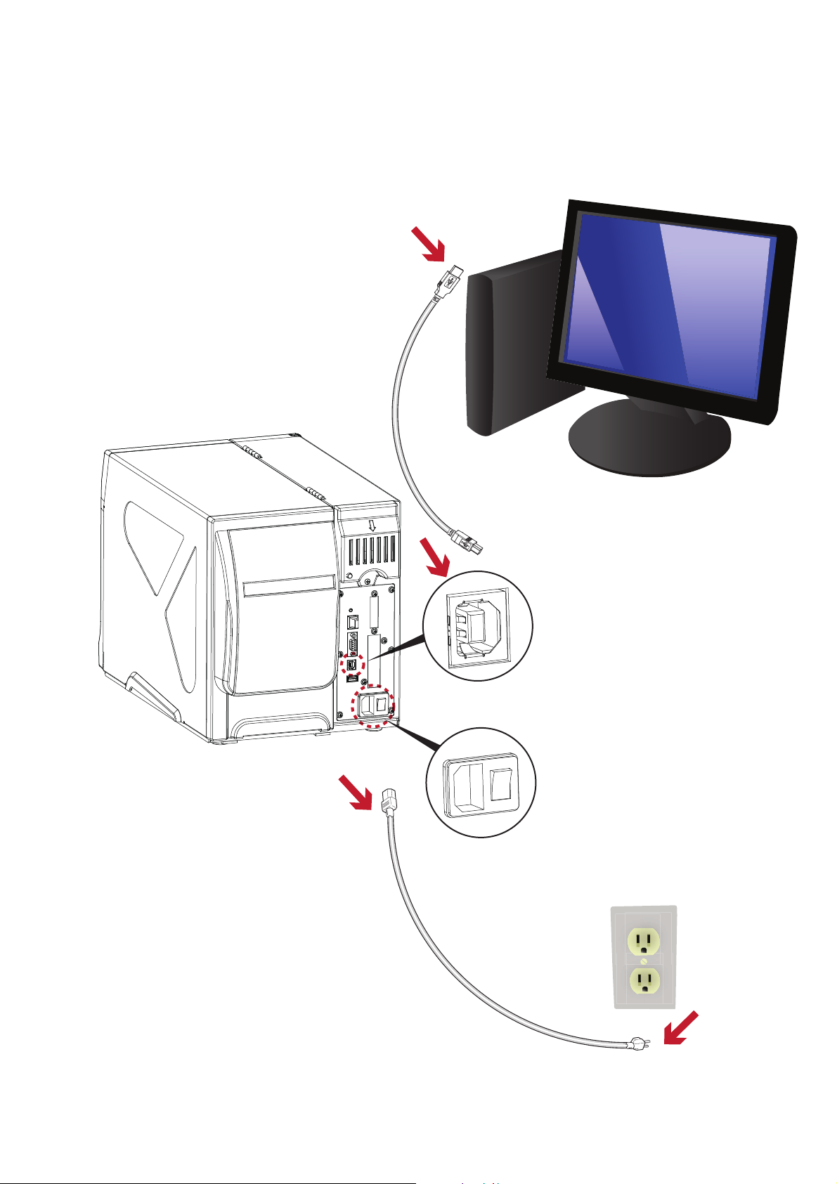
2.3 Connecting the Printer to your Computer
1. Ensure that the printer is turned off.
2. Connect the power cord to the printer. Plug the power cord into an electrical outlet.
3. Connect the USB cable to the printer and your computer.
4. Turn the printer on. The LCD should light up.
10
Page 15
2 Printer Setup
2.4
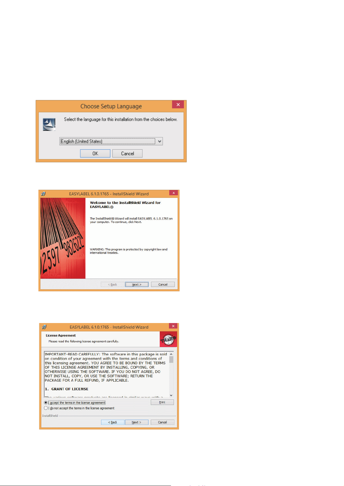
EASYLABEL Start Installation
2. The EASYLABEL InstallShield Wizard starts. Click “Next” to continue.
3. The next screen you can read EASYLABEL’s License Agreement. Click the “I accept the terms in the license agreement”
radio button and click “Next” to continue the installation.
1. Insert the product CD into CD/DVD drive of your computer. Open the "install” folder on the CD.
Right click on the setup.exe icon and choose “Run as Administrator” to start the installation.
Select a language for the installation and click OK to continue.
EASYLABEL Start is the free labeling package included with every Tharo printer.
11
Page 16
2 Printer Setup
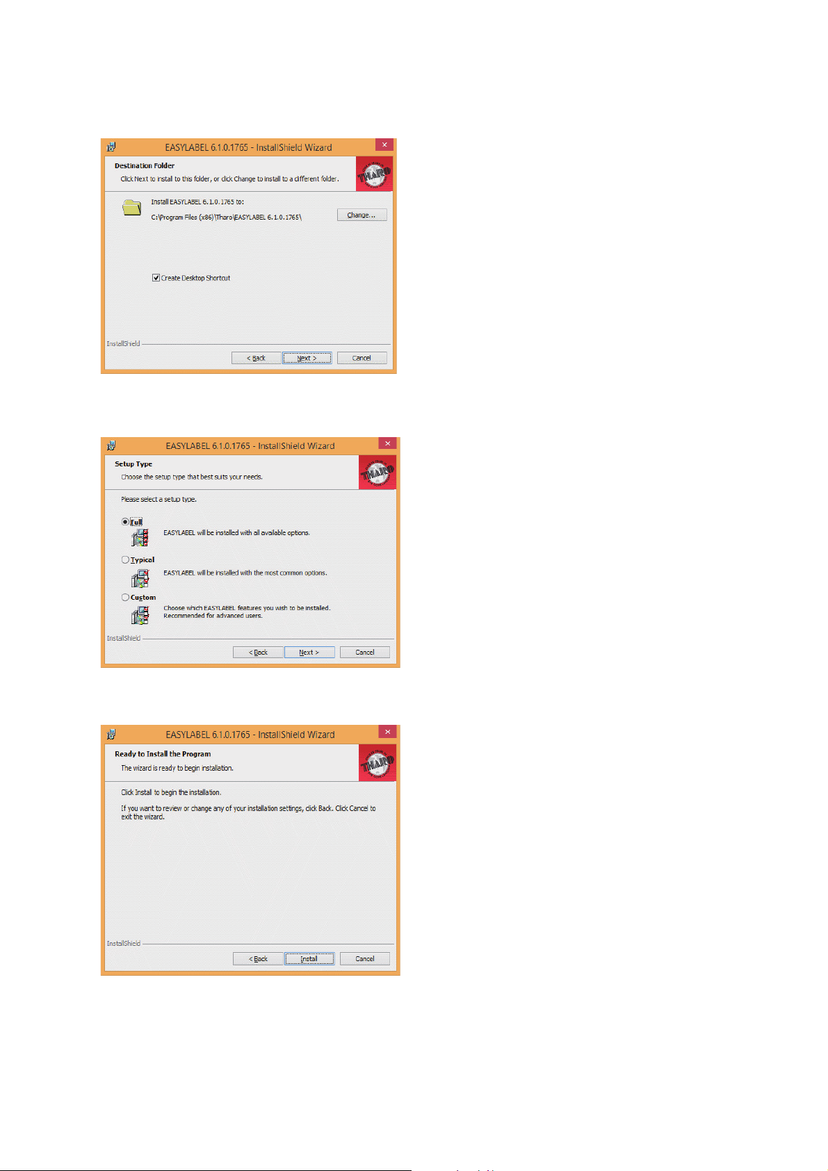
4. The next screen allows you to specify the directory to install EASYLABEL into. In most cases the default is fine.
You may also specify if you want an EASYLABEL icon on your desktop. Click on “Next” to continue.
5. The next step allows you to specify the installation type. “Full” is recommended for most users. Click “Next” to continue.
6. This is the confirmation screen. Click Install to install EASYLABEL Start.
12
Page 17
2 Printer Setup
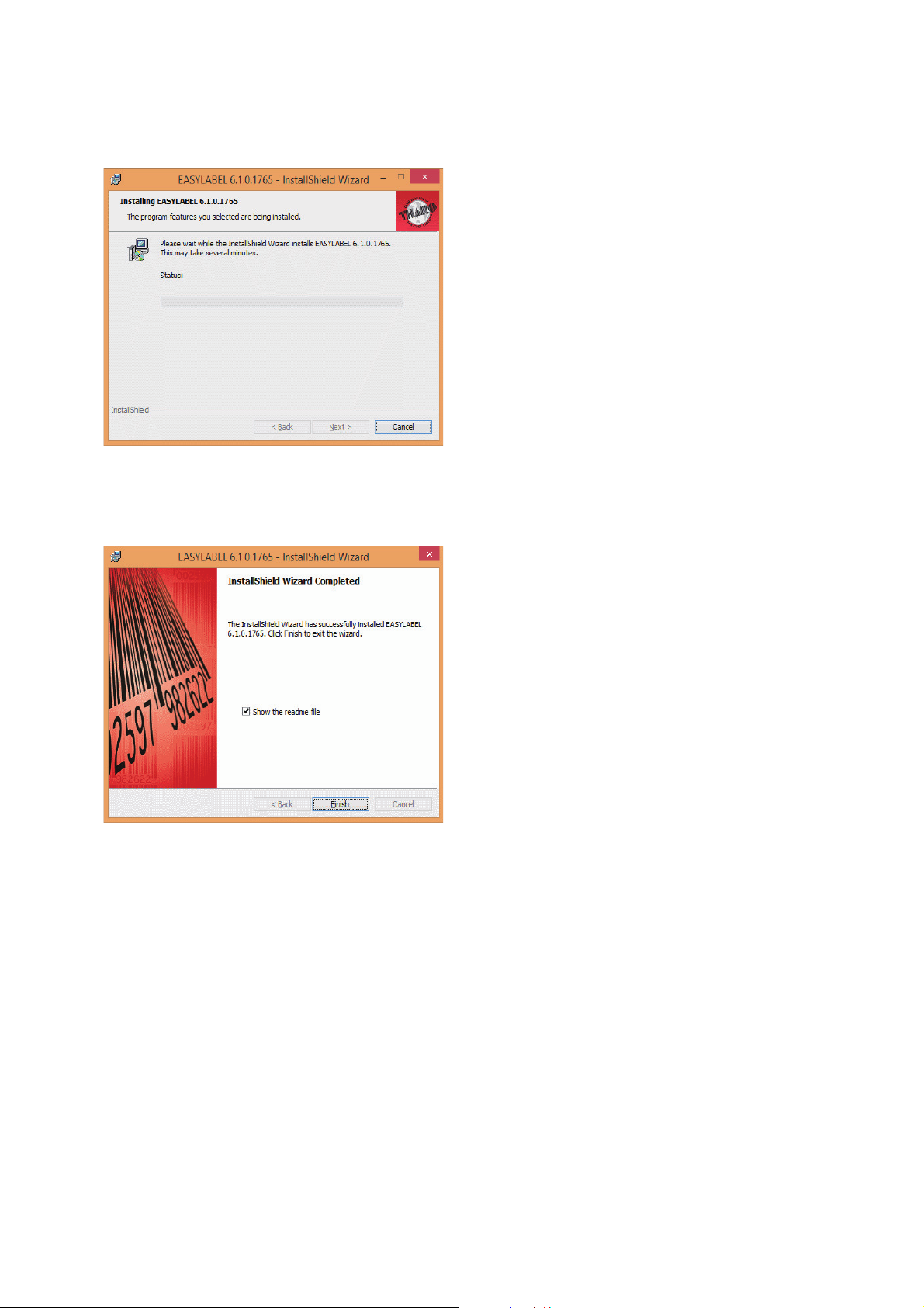
8. The installation is complete. Click “Finish” to close the InstallShield Wizard.
9. You are ready to start using EASYLABEL. If you are a new EASYLABEL user we recommend that you view the
EASYTutor tutorials. EASYTutor is the best way to get acquainted with your new labeling software. EASYTutor
can be found in the “EZtutor” folder on the product CD.
You may also view EASYTutor online at www.tharo.com/interactive.php
We suggest getting started with “Adding a USB printer” which is a great step-by-step walk through of how to
add a USB printer to EASYLABEL.
www.tharo.com/Interactive/adding_a_usb_printer/adding_a_usb_printer.htm
7. The Status screen will show the progress of the EASYLABEL Start installation.
13
Page 18

2 Printer Setup
Windows Drivers are NOT needed when printing to your Tharo Printer with EASYLABEL.
If you want to print to your Tharo Printer from other Windows applications then a Windows driver is needed.
STOP!
Do NOT plug the Printer's USB cable into your computer yet. There are some special installation steps for
Windows 8 and 10 users. If you are NOT using Windows 8 or 10 you can skip to the next page.
To install the Printer driver in Windows 8 or 10:
1. Open the "Tharo_Driver_Win8_Win10" folder.
2. Right Click on thr.inf and select "install"
3. Click on “Yes”
4. When the install finishes, Click on “OK”
5. Then plug the Printer's USB cable into your computer.
The printer should now be ready for use in Windows 8 or 10.
If you plugged in the printer without doing the above steps first, the printer is installed as an "Other Device"
and you will have to install the driver this way:
1. Open the Windows Control Panel
2. Click on "Hardware and Sound"
3. Under "Devices and Printers" heading click on "Device Manager"
4. Expand "Other Devices"
5. Right-click on the Tharo Printer and select "Update Driver Software"
6. Select "Browse my computer for driver software"
7. Click “Browse” and browse to where the "Tharo_Driver_Win8_Win10" folder and then click on “Next”
8. Click on “Install”
9. Click on “Close” to exit the wizard
The printer should now be ready for use in Windows 8 or 10.
Insert the product CD into CD/DVD drive of your computer.
2.5 Windows Driver Installation
14
Page 19
2 Printer Setup
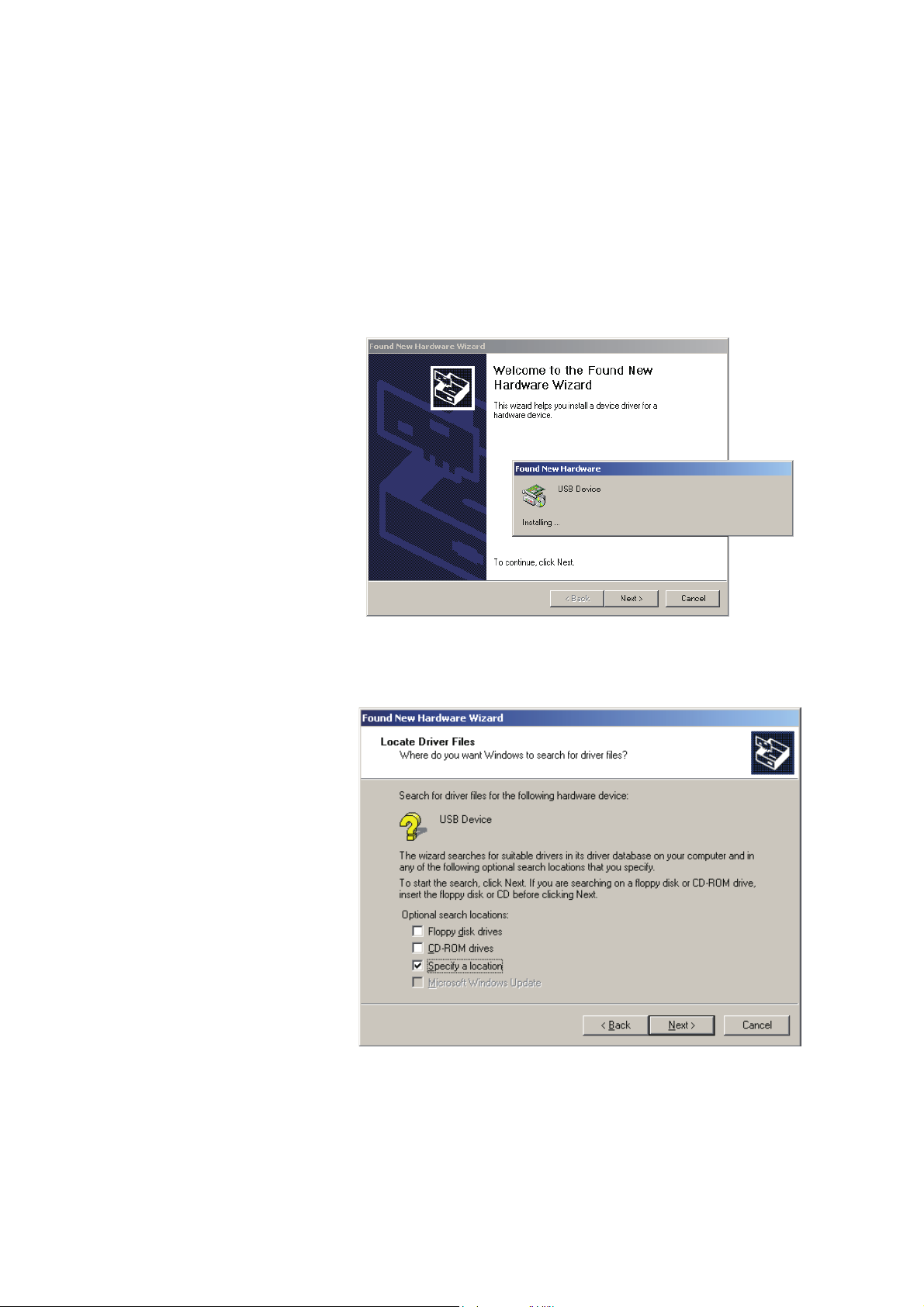
1. USB is a Plug & Play
facility. Once the USB
cable is connected
from PC to the printer,
the PC will
automatically detect
the new device and
begin the installation
process.
2. Select ‘Specify a
location’ and specify
the path of the printer
driver.
3. Follow the instructions
in the Wizard to
complete the
installation.
www.tharo.com
The printer can be installed on Windows releases other than Windows 8 or Windows 10 without any special
steps.
Insert the product CD into CD/DVD drive of your computer.
Turn the printer on and connect it to your computer with a USB cable.
The “Found New Hardware Wizard” should take over and install the drivers.
At some point you will be able to specify a location of the drivers.
Simply point the Wizard to the thr.inf file in the Windows Driver folder on the product CD.
15
Page 20
3 Printer Setting and Control
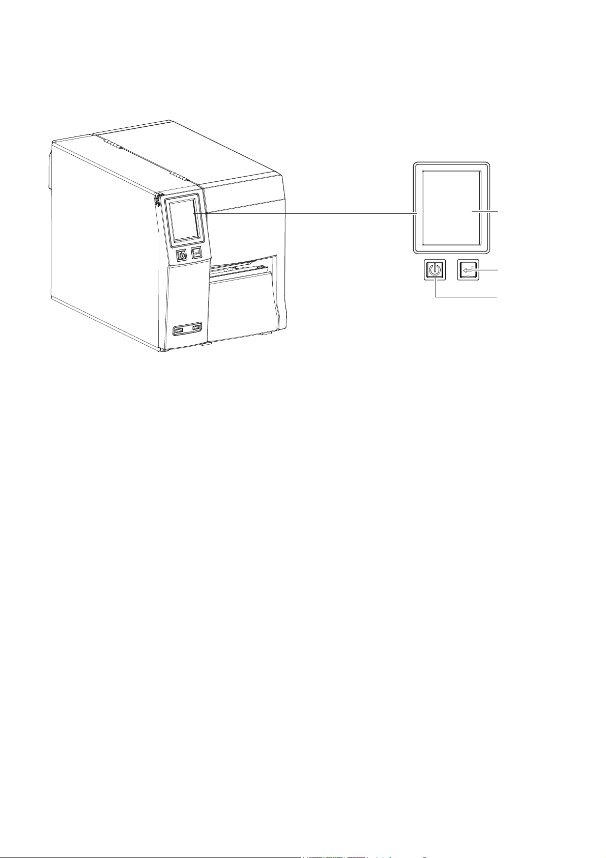
3.1 Operation Panel
FEED BUTTON
POWER BUTTON
TOUCH PANEL
POWER Button
Press the POWER button to turn on the printer.
Press and hold the POWER button for 3 seconds to turn the printer off.
FEED Button
Press the FEED button to advance the media.
If you are using continuous labels, the printer will advance a length of media.
If you are using media with gaps or black marks, the printer will advance one label.*
*If the printer feeds more than one label or the label does not stop in the correct position, you should perform a label calibration for your media.
See Section 3.4 Label Calibration and Self-Test.
PAUSE PRINTING using the FEED Button
Pressing the FEED button while the printer is printing will PAUSE the printer.
When the FEED button is pressed again, the printer resumes printing.
Example: While a 10-label print job is running, you press the FEED button to pause the printer.
Two of the labels have been printed. To resume printing and print the remaining eight labels, you will need to press
the FEED button again.
CANCEL PRINTING using the FEED Button
Press and hold the FEED button for 3 seconds while the printer is printing to CANCEL the print job.
The current print job is then cancelled.
Example: While a 10-label print job is running, you press and hold the FEED button for 3 seconds.
Two of the labels have been printed.
The print job is cancelled and the remaining eight labels will not be printed.
16
Page 21
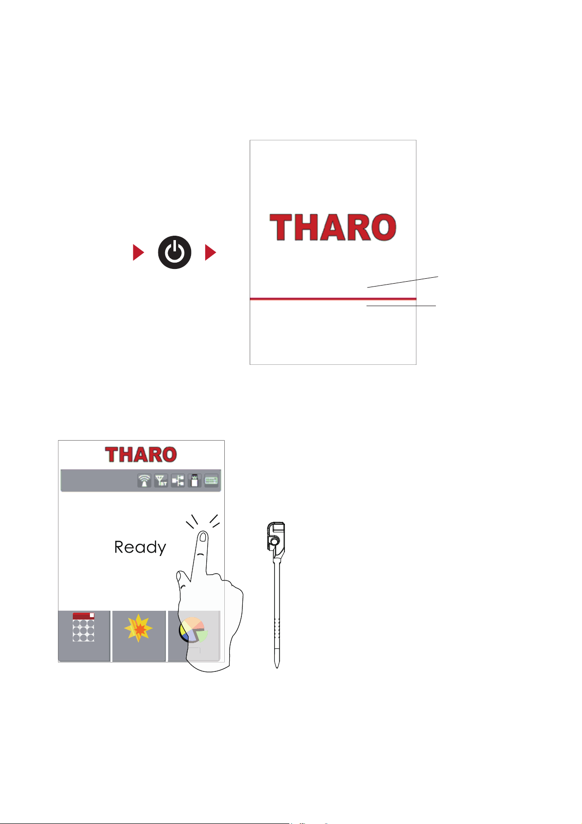
3 Printer Setting and Control
3.2 LCD Interface Introduction
Getting Started
Press the POWER button to turn on the printer. You will see the START UP SCREEN while the printer is booting up.
Power on
Once the printer has booted, the LCD screen will display “Ready“.
This indicates the printer is online and ready for use.
Tap the screen with your finger or the stylus pen when you want to select
on screen items such as settings icons.
17
Image 2.002
2.003-140805
LCD Firmware Version
LCD Image Version
Wizard
Test
Main
T-4210 V2.0000
Page 22
3 Printer Setting and Control
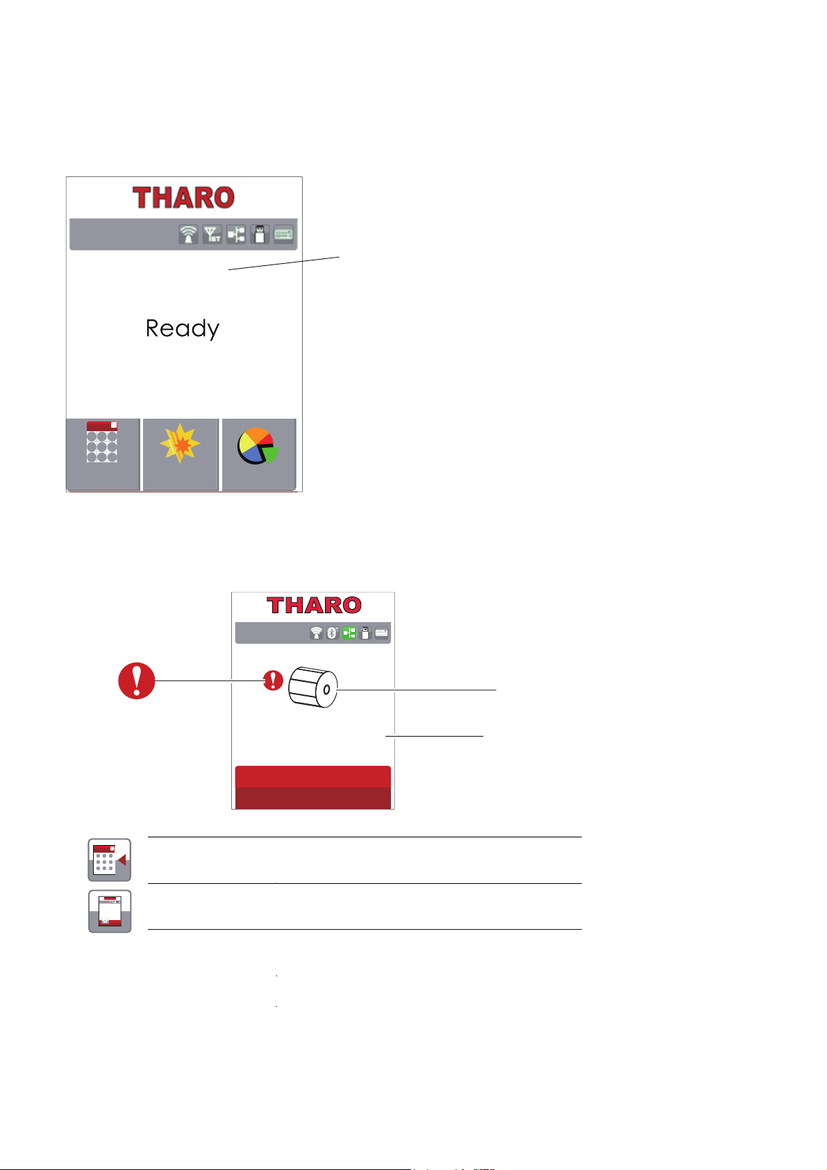
Icon Definition
Status of LCD Interface
When the printer is in standby (ready to print), the LCD will display “Ready” on screen.
You can only print when you see the “Ready“ status.
The LCD screen will display error messages on the screen when they occur.
See section 3.5 for the list of errors, causes and solutions.
WARNING ICON
ERROR DESCRIPTION
ERROR ICON
8SRQHOHYHO
7DSWKLVLFRQWRJREDFNRQHOHYHO
0DLQ0HQX
7DSWKLVLFRQWRHQWHURUUHWXUQWRWKHPDLQPHQX
18
Printer Model and Firmware Version
Wizard
Test
Main
T-4210 V2.0000
Check Media
Page 23
3 Printer Setting and Control
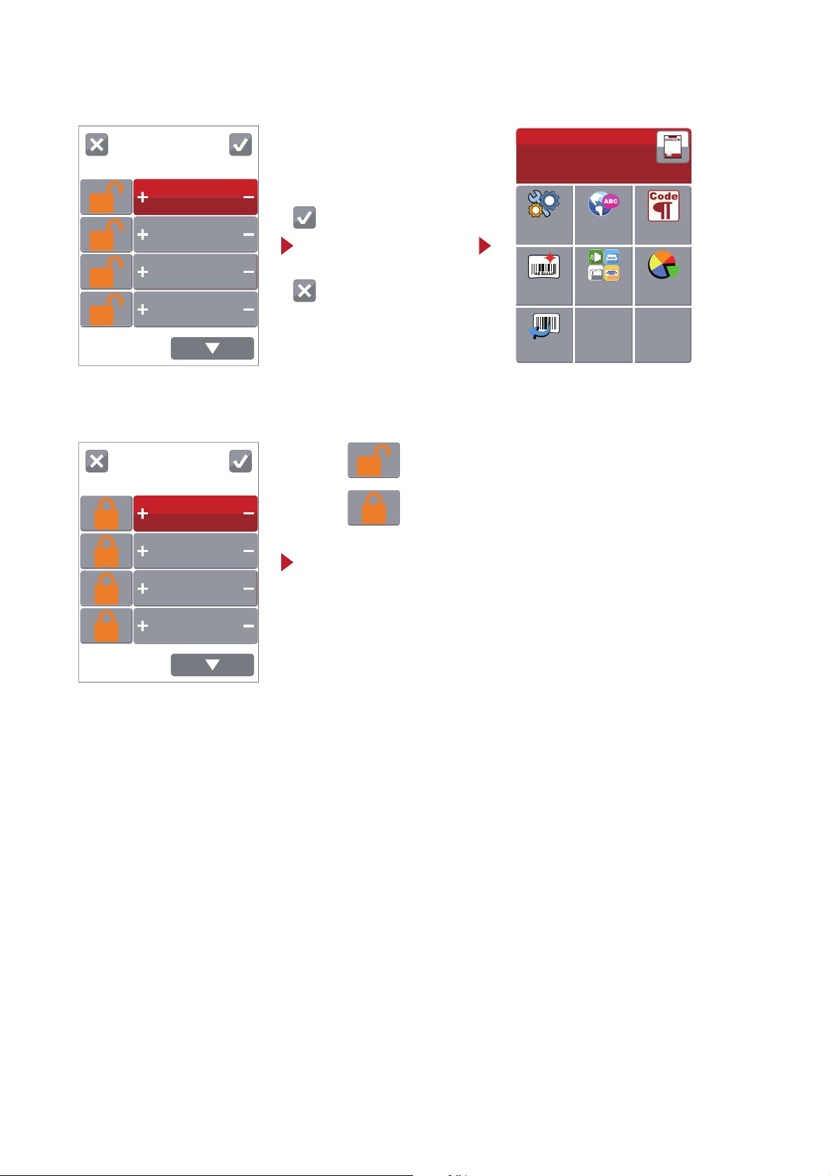
Tap this button to accept
the changes and return
to the main page
Tap this button to Cancel
the changes and return to
the main page.
Printer Settings
Continuous
Auto Select
6
10
Darkness
Speed
Sensor
Select
Media
Type
Main
LCD
Language
Printer
Settingss
Label
Settings
Devices
Printer
Control
Code Page
Recall
Label
Printer Settings
Continuous
Auto Select
6
10
Darkness
Speed
Sensor
Select
Media
Type
If the printer setting is UNLOCKED, the printer will process any commands
to change that setting. Tap the UNLOCKED icon to LOCK
If the printer setting is LOCKED, the printer will ignore any commands
to change that setting. Tap the LOCK icon to UNLOCK
UNLOCKED
LOCKED
19
Page 24
Wizard
0
Continuous
6
10
Darkness
Speed
Media
Type
0
X-Offset
Y-Offset
Test
Self-Test page
Calibration
Main
LCD
Language
Printer
Settings
Label
Settings
Devices
Printer
Control
Code Page
Recall
Label
3 Printer Setting and Control
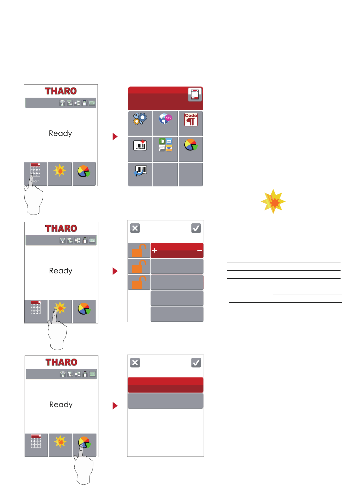
On the Ready Screen there are three icons that allow you to access three different menus.
Tap “Main”--
The screen now shows the “Main” Menu selections
allowing you to access the various printer settings.
Tap “Wizard”--
The screen now shows the “Wizard” menu selections
The Wizard menu provides quick access to the more
commonly changed printer settings.
Tap “Test”--
The Test screen allows you to perform a Label
Calibration and print a Self-Test page.
Darkness
Speed
0-19
Media Type
Label with Gaps
Label with Marks
Continuous
X-Offset
Y-Offset
2-10 see specification page
-100-100 (default 0)
-100-100 (default 0)
20
Wizard
Test
T-4210 V2.0000
Wizard
Test
Main
T-4210 V2.0000
Wizard
Test
Main
T-4210 V2.0000
Page 25
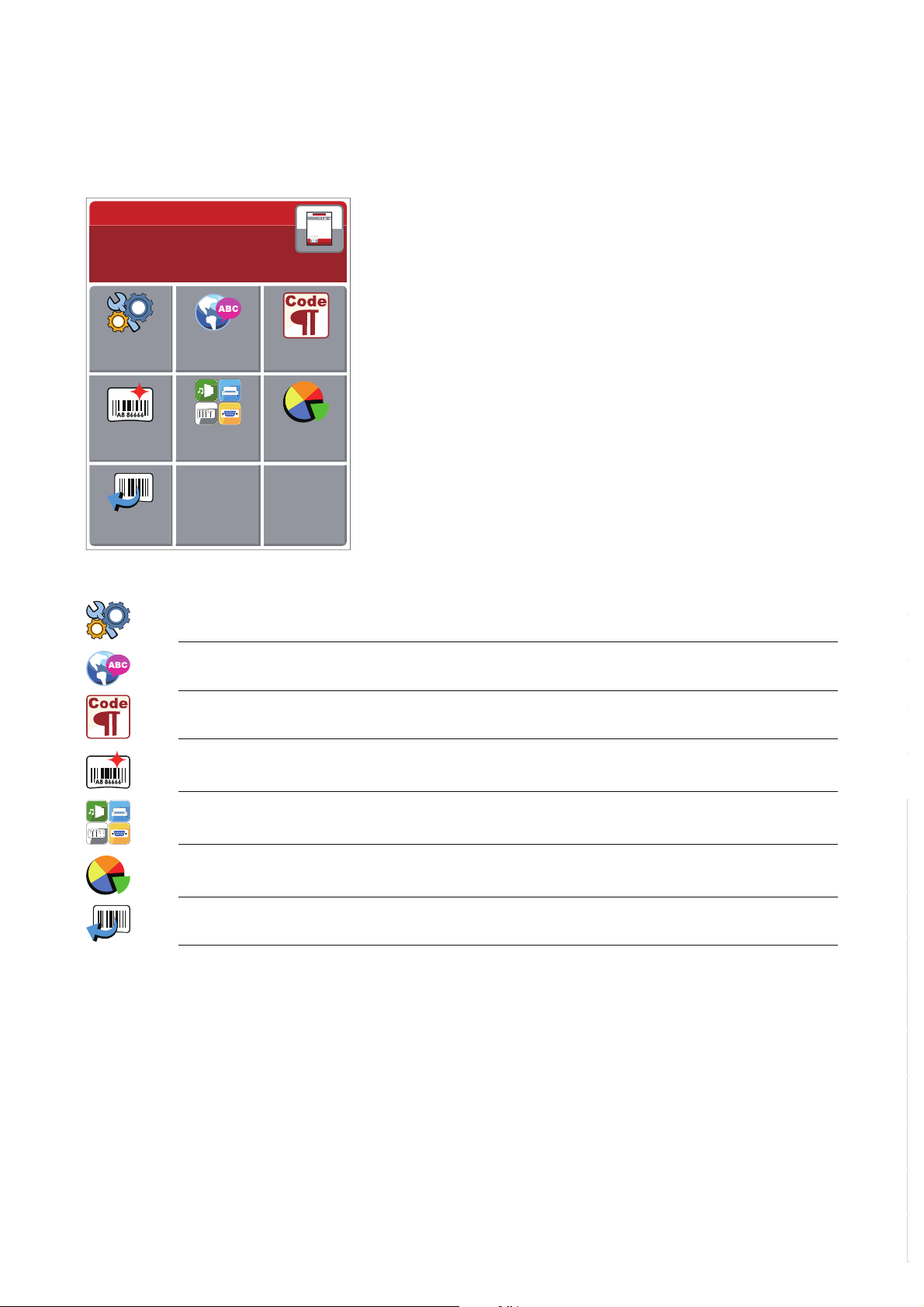
3 Printer Setting and Control
3.3 LCD Interface Functions
Main Menu
Main
LCD
Language
Printer
Settings
Label
Settings
Devices
Printer
Control
Code Page
Recall
Label
Printer Settings - Setting options for printing such as print speed, darkness, etc.
LCD Language- Allows selection of the language used in the printer’s LCD
Code Page- Allows selection of what Code Page to use when printing
Label Settings- Setting options for the label such as label rotat ion, print position, label offset, etc.
Devices- Setting options for optional modules and communication ports.
Printer Control- Includes self-diagnosis functions for the printer such as a TPH test and self-test page printing.
Recall Label- Allows the selection and printing of a label stored in memory.
21
Page 26
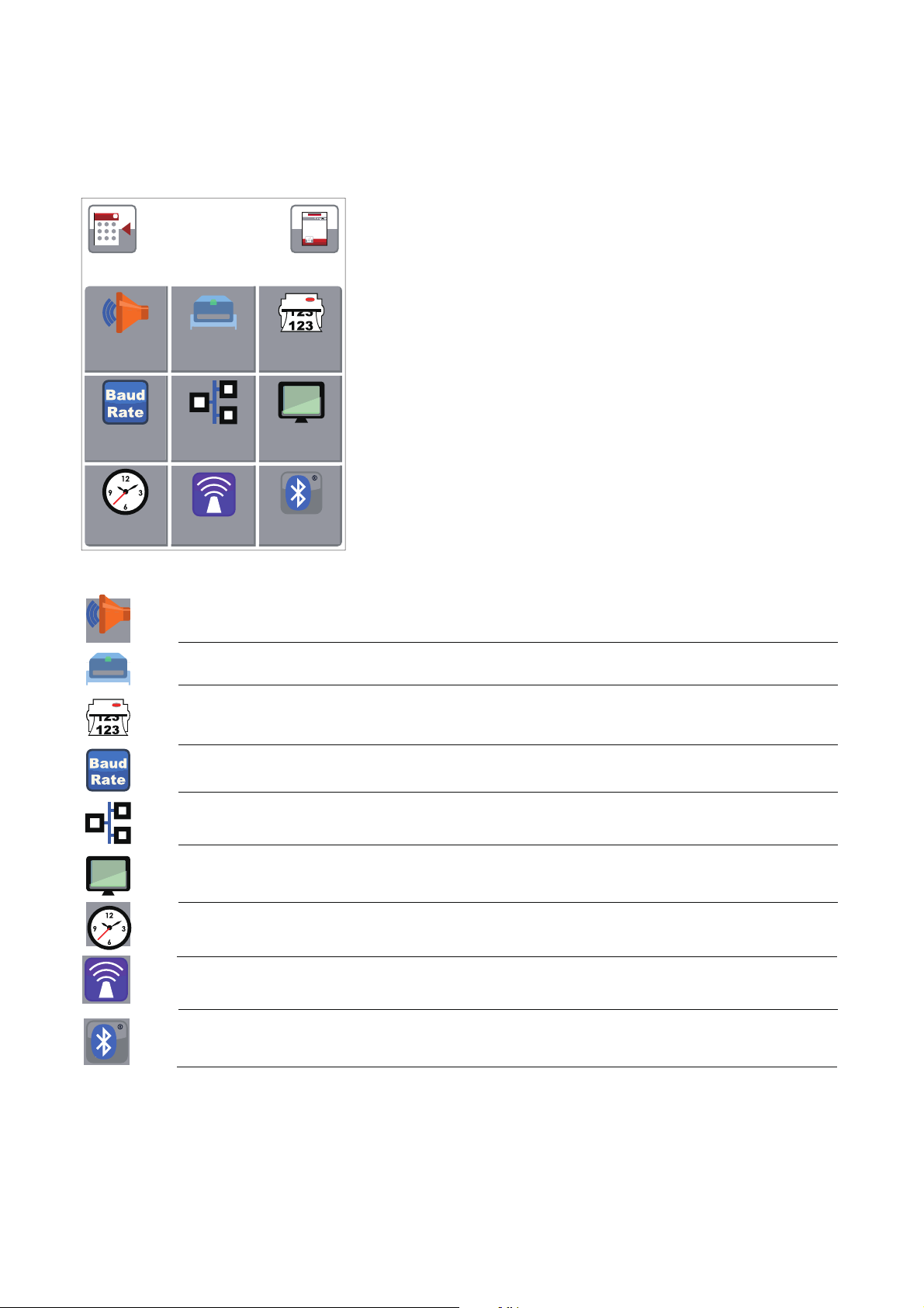
Devices
Buzzer
Option
Setting
Smart
Backfeed
Serial Port
Settings
LAN
Settings
LCD
Settings
Clock
Settings
3 Printer Setting and Control
Devices Menu
Buzzer- Defines operation of Buzzer. When this option is turned on the printer will sound the buzzer (beep)
for most events. When this option is turned off the printer will only sounds the buzzer (beep) when there
is a condition that requires the operator’s attention.
Option Setting- Used to specify the presence of the optional Cutt er, Label Dispenser or Applicator Interface
Smart Backfeed- When in stripper, applicator, or cutter mode, a label is printed and moved forward to
be peeled off, taken by applicator or cut. If Smart Backfeed is ON, the next label will be partially printed
so the printer does not have to backfeed to find the original starting point when printing continues.
Serial Port Settings- Options to configure the Serial Port such as Baud Rat e, Parity, Data Bits, Stop Bits.
LAN Settings- Options to configure the wired LAN such as DHCP, IP Address, Gateway, Subnet Mask.
LCD Settings- Has an option to password protect access to the LCD menu and a Calibration function
for the touch screen.
Clock Settings- Allows for setting the Printer’s Clock, ex. Year, Month, Day, Hour, Minute
WiFi Settings- Options to configure the WiFi module in order for the Printer to join a wireless network
Bluetooth Settings- Options to configure the Printer so it may join a Bluetooth network.
WiFi
Settings
Bluetooth
Settings
22
Page 27
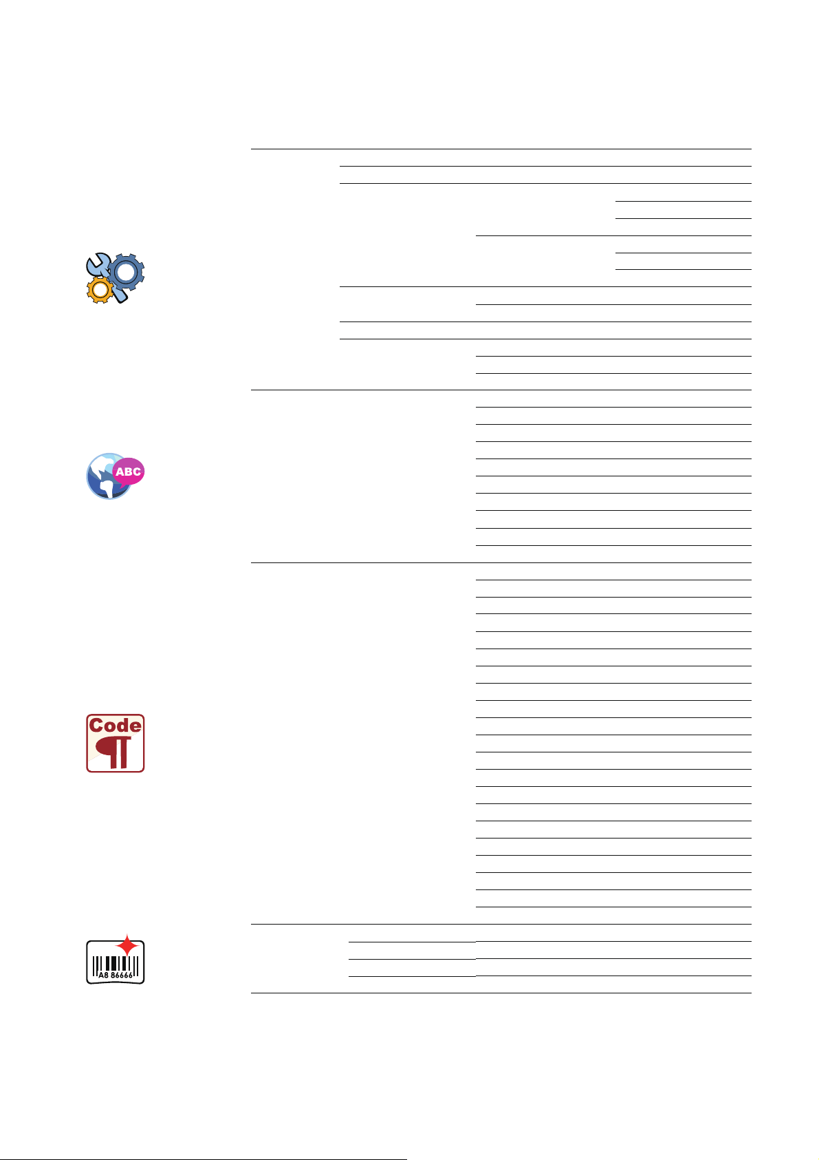
3 Printer Setting and Control
Available Menu Settings
Printer Setting
Darkness
0-19
Speed
2-
Sensor Select
Media Detection
Auto Select
See-Through
Reflective
Media Type
Label with Gaps
Label with Marks
Continuous
Print Mode
Direct Thermal
Thermal Transfer
0-40
Top of Form
LCD Language
English
Deutsch
丨檻Ḕ㕮
䰈檻Ḕ㕮
Français
Español
㗌㜓媅
Italiano
Pусский
Türkçe
Code Page
850
852
437
860
863
865
857
861
862
855
866
737
851
869
Win 1252
Win 1250
Win 1251
Win 1253
Win 1254
Win 1255
Win 1257
Label Settings
Rotation
X-offset
Y-offset
Start Offset
10 based on print resolution see specification page
FULL
Tear-Off Position
OFF
TPH Open Only - After Print Head is opened/closed
0°, 90°, 180° or 270°
-100-100 (default 0)
-100-100 (default 0)
-100-100 (default 0)
23
s
Page 28
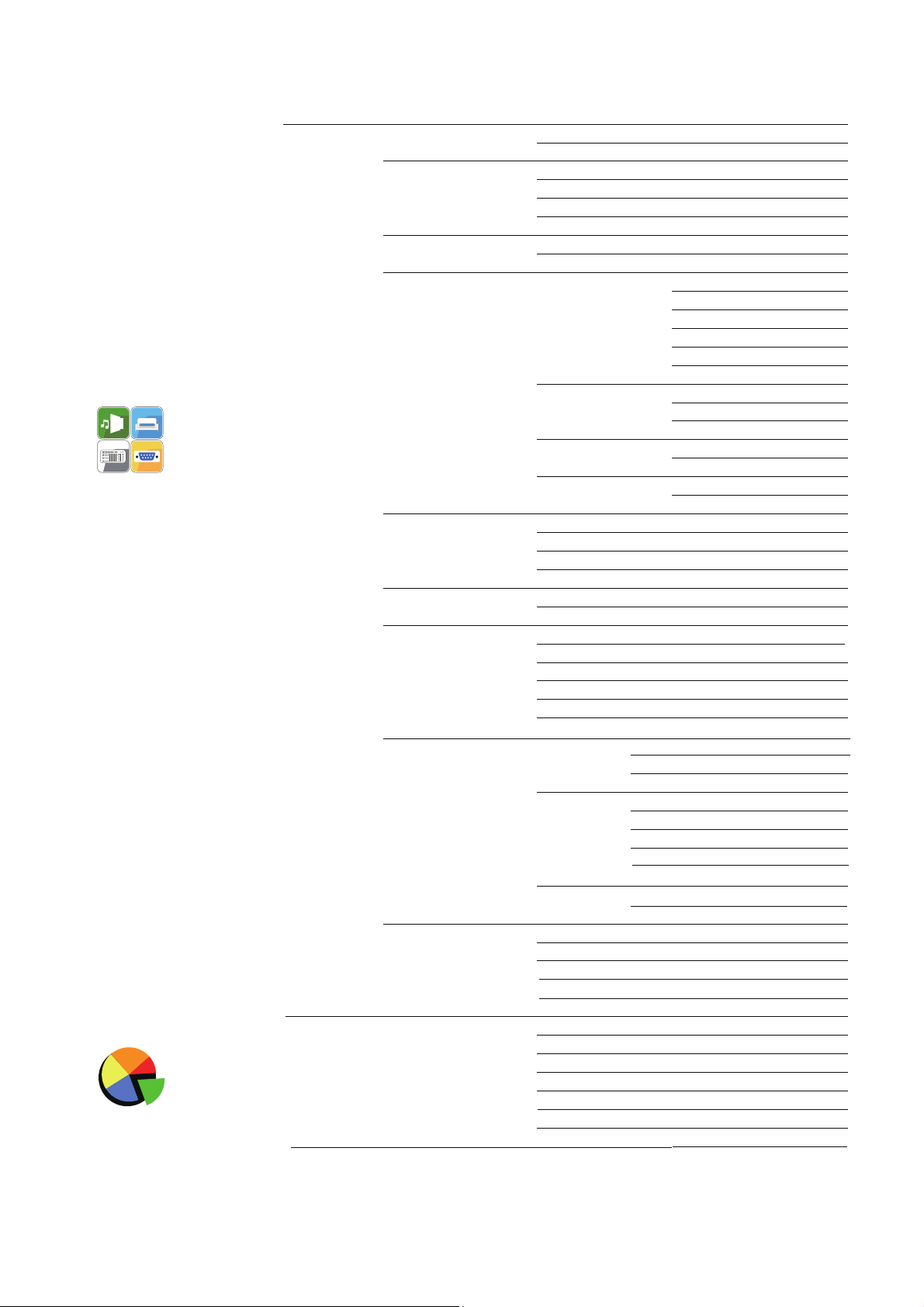
3 Printer Setting and Control
Devices
Buzzer
OFF
ON
Option Setting
None
Cutter
Label Dispenser
Applicator
Smart Backfeed
Off
On
Serial Port Settings
Baud Rate
4800 bps
9600 bps
19200 bps
38400 bps
57600 bps
115200 bps
Parity
None
Odd
Even
Data bits
7 bits
8 bits
Stop bits
1 bits
2 bits
LAN Settings
DHCP
On
IP Address
0.0.0.0
Subnet Mask
255.255.255.0
Gateway
192.168.0.254
LCD Settings
Password
OFF
Clock Settings
Year
Month
Hour
Minute
Printer Control
Test
Sample Pattern
Select Memory
Clear Memory
Calibration
Restore Defaults
Bluetooth Settings
Clear Bind
Make Device Visible
SSP
PIN Code
Search Devices
Calibration
Visible (on LCD) ON/OFF
Day
WiFi Settings
24
Printer Info -Print Length and Cutter Count
WLAN Details
WEP
Encryption
WPA/WPA2
Encryption
Module Active ON/OFF
SSID
Security None, WEP, WPA, WPA2
Auth Open, Shared Key
Default Key 1-4
WEP Key Disable, 40 bits, 128 bits
Key Format Hex, ASCII
Pre-Shared Key TKIP, AES
Key
Key
ON/OFF
ON/OFF
ON/OFF
ON/OFF
0000
Page 29
3 Printer Setting and Control
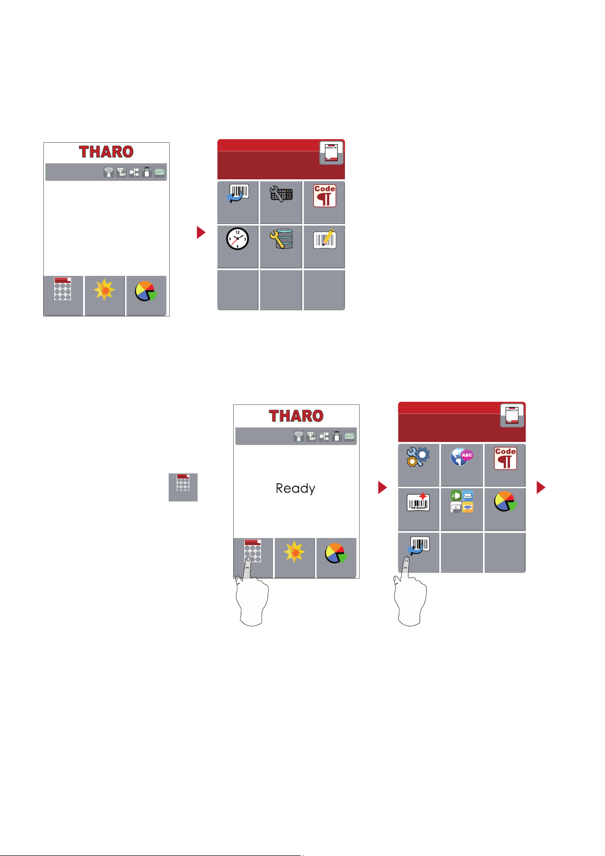
Keyboard Mode
When a USB keyboard is plugged into the printer, the LCD will prompt “Enter Standalone”. Press the “Y” key
on the keyboard to enter the “Keyboard Mode” menu.
Enter Standalone ?
(Y/N)
Keyboard Mode
Country
Code
Edit
Label
Database
Settings
Code Page
Recall
Label
Clock
Settings
Recall Label function
Allows the user to Recall any labels in the printer and preview them.
Main
LCD
Language
Printer
Settings
Label
Settings
Devices
Printer
Control
Code Page
Recall
Label
From the Home screen, tap
to enter the Main Menu.
From the Main Menu tap Recall Label
to enter the Recall Label Menu.
Main
25
Wizard
Test
Main
T-4210 V2.0000
Wizard
Test
Main
Page 30
3 Printer Setting and Control
0
0°
0
Preview
Label
Recall Label
5
5
15
001/002
FORM NAME
LABEL-1
LABEL-2
0
0°
0
Preview
Label
Recall Label
5
5
15
T-4210
FW:V2.000
Recall Label
Prompt
001
Recall Label
Print Quantity
1
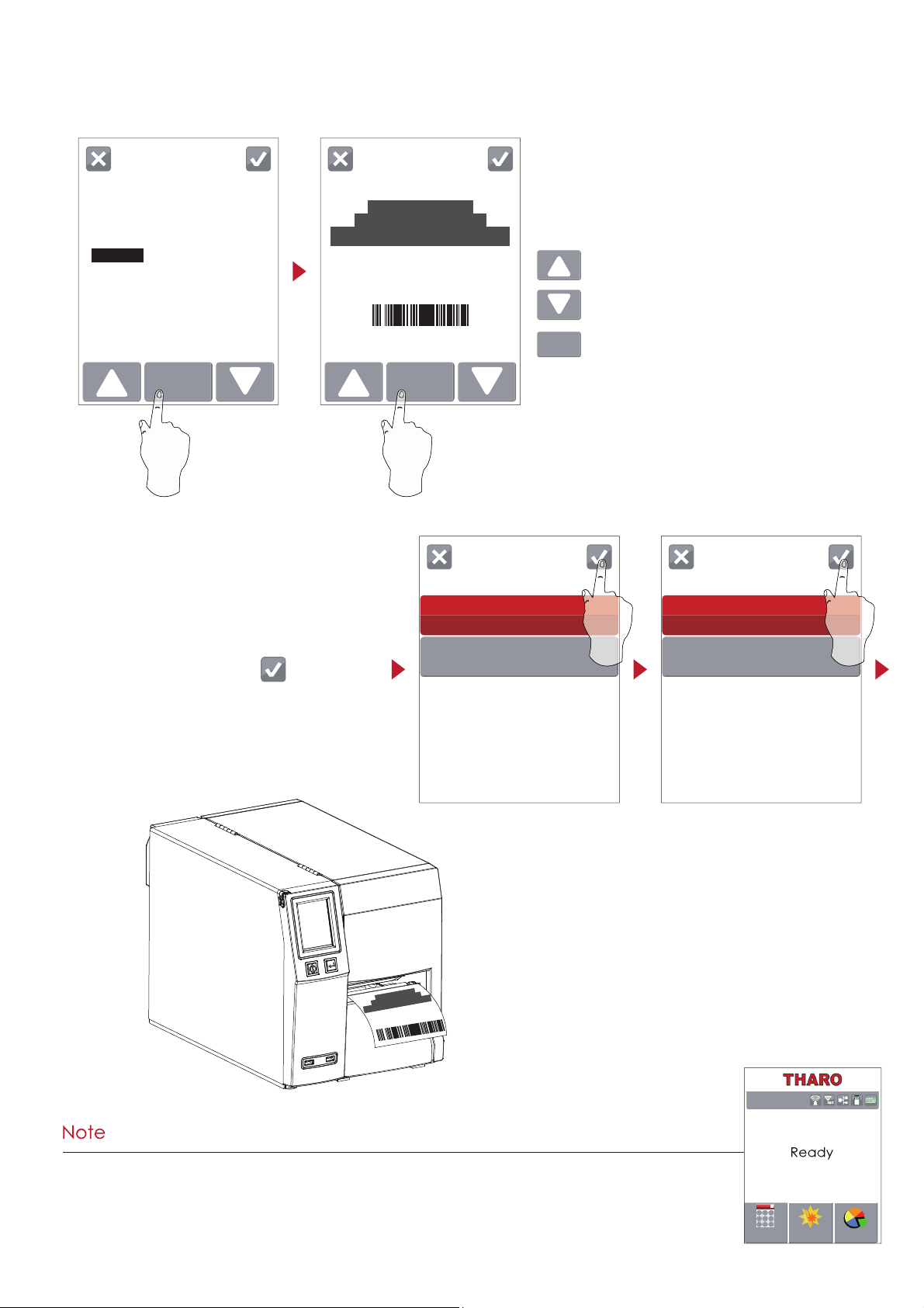
The Recall Label Menu allows review
and selection of labels,
Tap up to move up the list of labels
Tap down to move down the list of labels.
Tap Preview Label to see a preview of the label.
Preview
Label
Keep taping to move to
the next page
T-42120
FW:V2.000
The selected label prints.
***After using the recall label function the printer returns to the Ready Page.
26
Wizard
Test
Main
T-4210 V2.0000
Page 31

3 Printer Setting and Control
Label Calibration
The printer can automatically detect and store label height.
That means the host computer does not need to transmit the label height to the printer.
3.4 Label Calibration and Self Test
Self Test
The Self Test function lets you check whether the printer is functioning normally.
Follow these steps to run the Label Calibration and Self Test.
1. Check that the label stock is loaded correctly.
2. Turn off the printer and press the FEED key.
3. Turn the printer on, keeping the FEED button pressed. When the LED around the power button starts to flash red,
release the FEED button. The printer will now perform a Label Calibration.
4. Once the Label Calibration is complete, the printer will print a Self Test label.
The contents of a sample self-test printout can be seen below.
Model & Version
USB ID setting
Serial port setting
MAC address of Ethernet port
IP address of Ethernet port
Gateway setting
Netmask setting
PORT State
(L=LPT, S=Serial, E=Ethernet, U=USB, B=Bluetooth)
PORT State (1= On, 0=Off)
Number of forms
Number of graphics
Number of fonts
Number of Asian fonts
Number of Databases
Number of Scalable fonts
Free memory size
Speed, Density, Ref. Point, Print direction
Label width, Form length, Stop position
Cutter, Label Dispenser, Mode
Sensor Setting
Code Page
T-4210 VX.XXX
USB S/N: 12345678
Serial port: 96,N,8,1
MAC Addr: xx-xx-xx-xx-xx-xx
IP xxx.xxx.xxx.xxx
Gateway xxx.xxx.xxx.xxx
Sub-Mask xxx.xxx.xxx.xxx
PORT State L S E U B
1 1 1 1 1
##################################
0000 FORM(S) IN MEMORY
0000 GRAPHIC(S) IN MEMORY
000 FONT(S) IN MEMORY
000 ASIAN FONT(S) IN MEMORY
000 DATABASE(S) IN MEMORY
000 TTF(S) IN MEMORY
4073 KB FREE MEMORY
^S4 ^H8 ^R000 ~R200
^W102 ^Q100,3 ^E18
Option:^D0 ^O0 ^AD
Ref. :1.96 2.84 2.49[0.88_23]
Code Page:850
27
Page 32
3 Printer Setting and Control
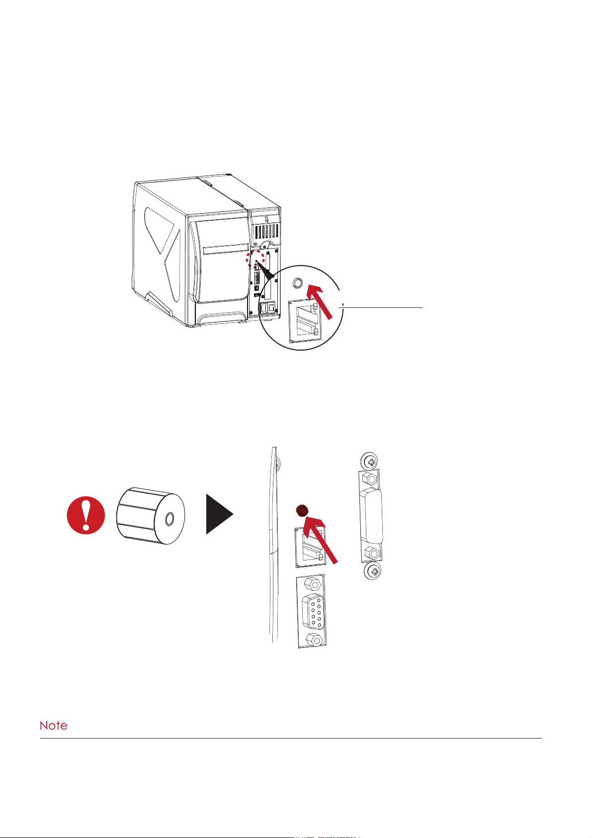
Label Calibration Button
The Label Calibration button is used to perform a Label Calibration.
This is useful to correct any Media Errors that may occur when changing the labels to another type,
such as changing gap labels to black mark labels or continuous media.
Press and hold the Calibration Button for 2 seconds to start the Label Calibration.
Press
****Pressing the Calibration Button is equivalent to the auto-sensing command ‘’~S,SENSOR’’.
Press
CALIBRATION BUTTON
28
Page 33
3 Printer Setting and Control
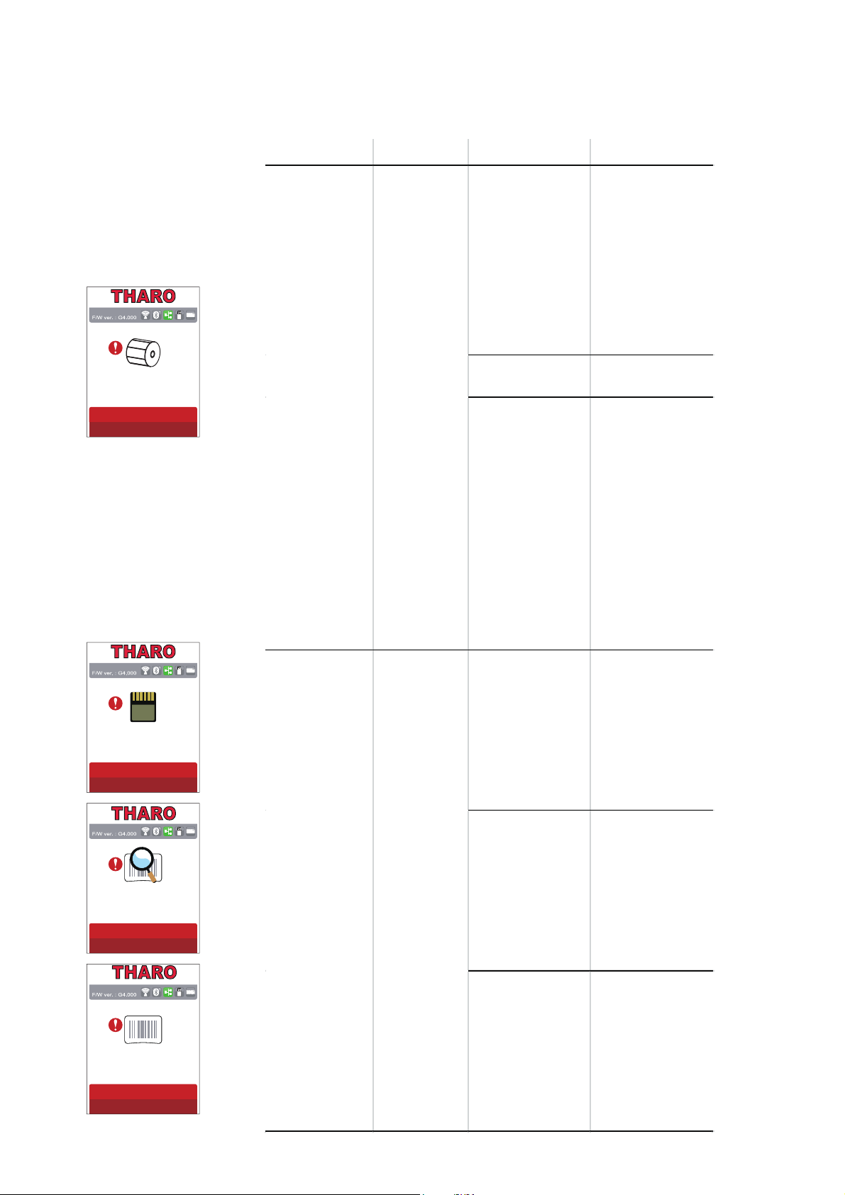
3.5 Error Alerts
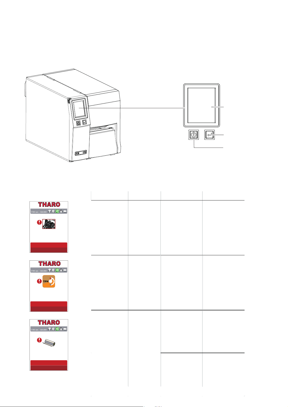
In the event of a problem that prevents normal functioning of the printer, you will see an error message on LCD
screen and hear some beep signals. Please refer to below table for the errors, causes and possible solutions.
Check ribbon
Type Beeps Description Solution
Print Head Error 2 x 4 beeps
The print head
mechanism is not
locked in place.
Open the print
mechanism and
close it again.
Print Head Error None
High temperature
at the print head.
Once the print
head has cooled
down, the printer
goes back to
standby mode.
No ribbon is
installed and using
Direct Thermal
label stock.
Make sure that
the printer is set to
Direct Thermal
printing mode.
The ribbon is
used up or the
label supply hub is
not mov ing.
Replace the
ribbon roll.
Media Error
2 x 3 beeps
FEED BUTTON
POWER BUTTON
/&'728&+3$1(/
Printhead Open
29
TPH Over Heat
Page 34
3 Printer Setting and Control
Type Beeps Description Solution
No labels are
detected.
Make sure that
the label sensor is
positioned
correctly. If the
sensor still does not
detect the paper,
run the auto-
detection
function again.
Label stock is
used up.
Replace the label
roll.
Printer feed
problem.
Possible reasons:
the print media
has become
trapped around
the rubber roller; the
sensor cannot
detect a gap or
black mark
betw een the
labels; there is no
paper. Please
reset the sensor.
The memory is full.
The printer prints
the message "File
System full ".
Delete
unnecessary data
or install
additional
memory.
Unable to find file.
The printer prints
the message "File
Name not found"
Use the "~X4"
command to print
all files. Then
check whether
the files exist and
whether the
names are
correct.
A file of the same
name already
exists. The printer
prints the message
"Duplicate Name".
Change the
name of the file
and try storing it
again.
File Error
2 x 2 beeps
Media Error
2 x 2 beeps
30
Check Media
File System Full
File Not Found
Duplicated Name
Page 35
3 Printer Setting and Control
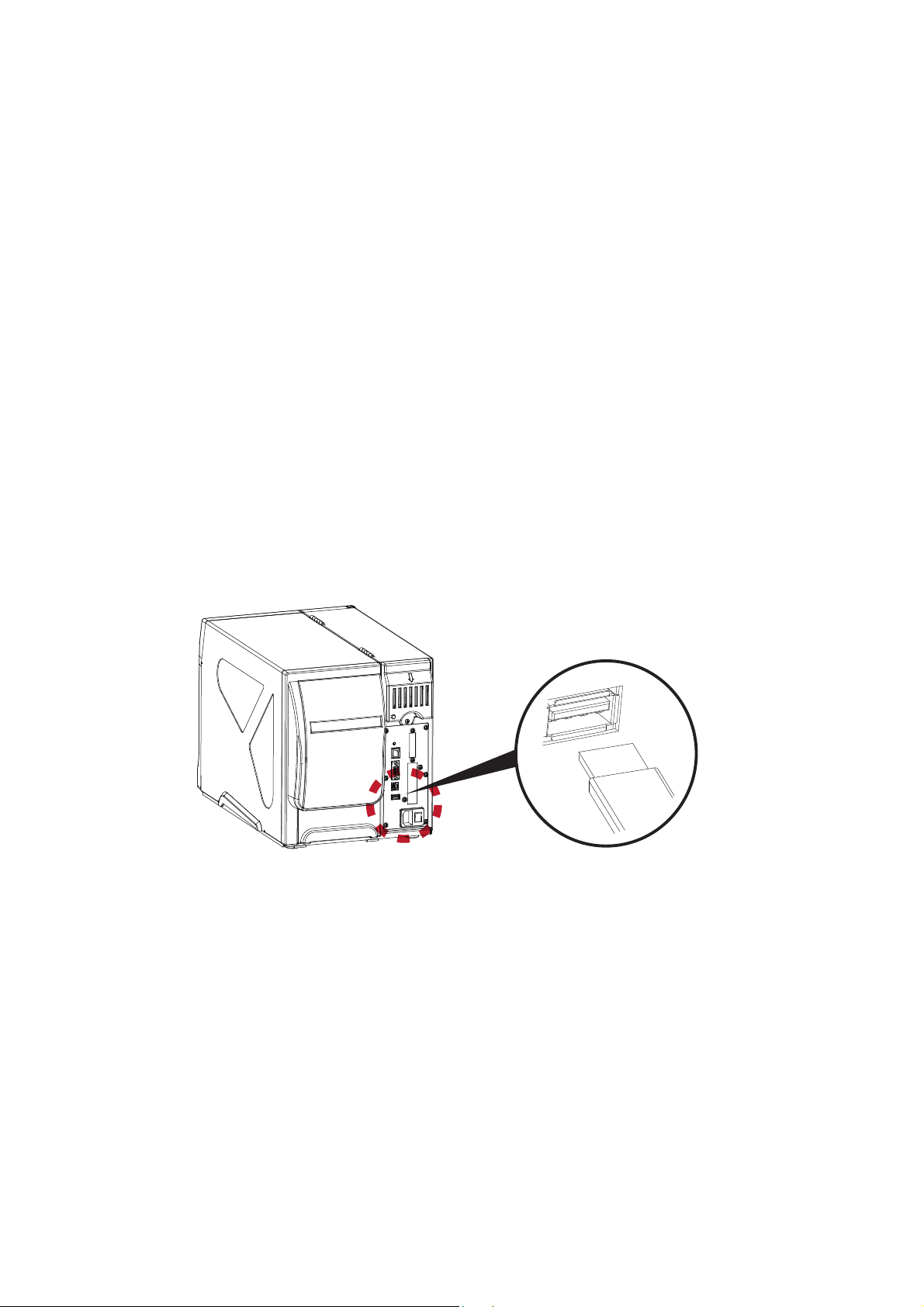
3.6 USB Host and Standalone Mode
USB Host Uses
The USB Host port supports the use of a USB memory stick, keyboard or scanner.
=
A USB memory stick can be used to extend the user accessible storage memory up to 32GB
The printer’s Firmware also can be updated using a USB memory stick.
=
Connect a USB keyboard to printer for Keyboard Mode/Standalone operation.
=
Plug-in an USB scanner to operate the printer in Keyboard Mode/Standalone.
Using Extended Memory
=
The printer will create a Folder called “\LABELDIR” and switch “User Flash” to “Extended Memory” automatically when
the user plugs a USB memory stick into the printer.
=
Connect the printer to a PC with the USB Stick plugged in and use EASYLABEL (Silver or higher) software to
download Graphics, Fonts, Label Formats and Database files to the printer.
Updating Firmware
=
Remove the USB memory stick from printer and plug-in it to a PC’s USB port. Delete any existing firmware (*.bin) file from
\LABELDIR\FW. If there is no FW folder in the LABELDIR directory, create one.
=
Copy the new firmware (xxxx.bin) into the Folder \LABELDIR\FW. Then remove the USB Memory Stick from the PC and
plug it back into the printer.
=
The printer will automatically update the firmware when the firmware on the USB stick is newer than the firmware loaded
in the printer.
=
Do Not remove the USB memory stick until the firmware is finished updating and you see ‘Ready’ on the LCD.
31
Page 36

3 Printer Setting and Control
** The USB Host port cannot be used as a USB HUB.
** The printer supports FAT32 formatted USB Memory Sticks up to 32GB only. The certified venders are Transcend,
Apacer, Patriot, Corsair and Kingston.
* The user may copy the entire \LABELDIR directory from the USB memory stick to the PC or vice-versa.
Copying of any of the individual subfolders or individual files in the LABELDIR directory is not supported.
USB Keyboard
=
Plug a USB keyboard into the printer and the “Enter Standalone?” prompt will appear on the LCD. Press the
“Y” key on keyboard to enter Standalone Mode. You can also press “F1” on the keyboard to enter Standalone Mode
from the “Ready” screen.
=
When in Standalone Mode the keys on the keyboard have the following functions:
1. Press the “ESC” key on the keyboard to go back to the previous dialog.
2. Use the Alphabetic keys and the Enter key on the keyboard as you usually would to enter variables and Print
Quantity when the printer prompts for them on the LCD when in Standalone Mode.
There are seven selections in Standalone Mode:
1. Recall Label - This selection allows you select a label that is stored in memory and print it.
2. Keyboard Country Code - This selection allows you to set the Country Code to match the keyboard you are using.
3. Code Page - This selection allows you to set the Code Page.
4. RTC Settings - This selection allows you to set the Real Time Clock (RTC)
5. Edit Database - This selection allows you to browse and edit records in any database stored in the printer memory.
It is NOT possible to add or delete records.
6. Edit Label - This selection allows you to edit the TPL of any label format that is stored in the printer memory.
7. Exit Standalone - This selection allows you to EXIT Standalone mode and return to the Ready screen.
Scanner
=
When a USB scanner is plugged into the printer the LCD will prompt “Enter Standalone?”. Tap the “Y” to
enter Standalone Mode operation.
=
In Standalone Mode the scanner can be used to enter variables and Print Quantity when the printer
prompts for them on the LCD.
32
Page 37
4 NetSetting for Ethernet
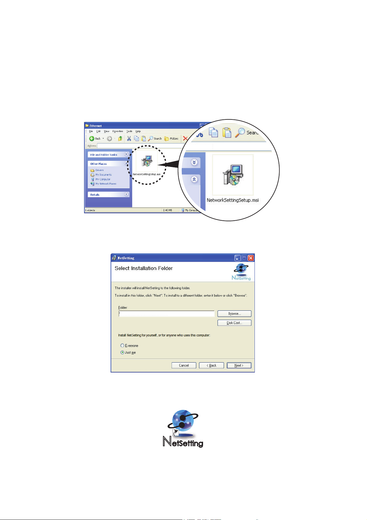
4.1 Installing the NetSetting software
The NetSetting software is used to manage the network configuration of the Ethernet port.
NetSetting is available on the CD that ships with the printer or it can be downloaded from our website (www.tharo.com).
To install NetSetting:
5. Click ”Next” to continue the installation.
6. Once the installation has completed, you will see the NetSetting icon on your desktop.
1. Insert the Printer CD in your computer’s CD/DVD drive. Browse the contents of the CD and open the "Ethernet" folder.
2. Doubleclick on the NetworkSettingSetup.msi icon to start the installation.
3. The Setup Wizard will guide you through the installation procedure. Follow the instructions on the screen.
4. Specify an “Installation Folder".
D:\Ethernet
C:\Program Files\Tharo\NetSetting\
33
Page 38
4 NetSetting for Ethernet
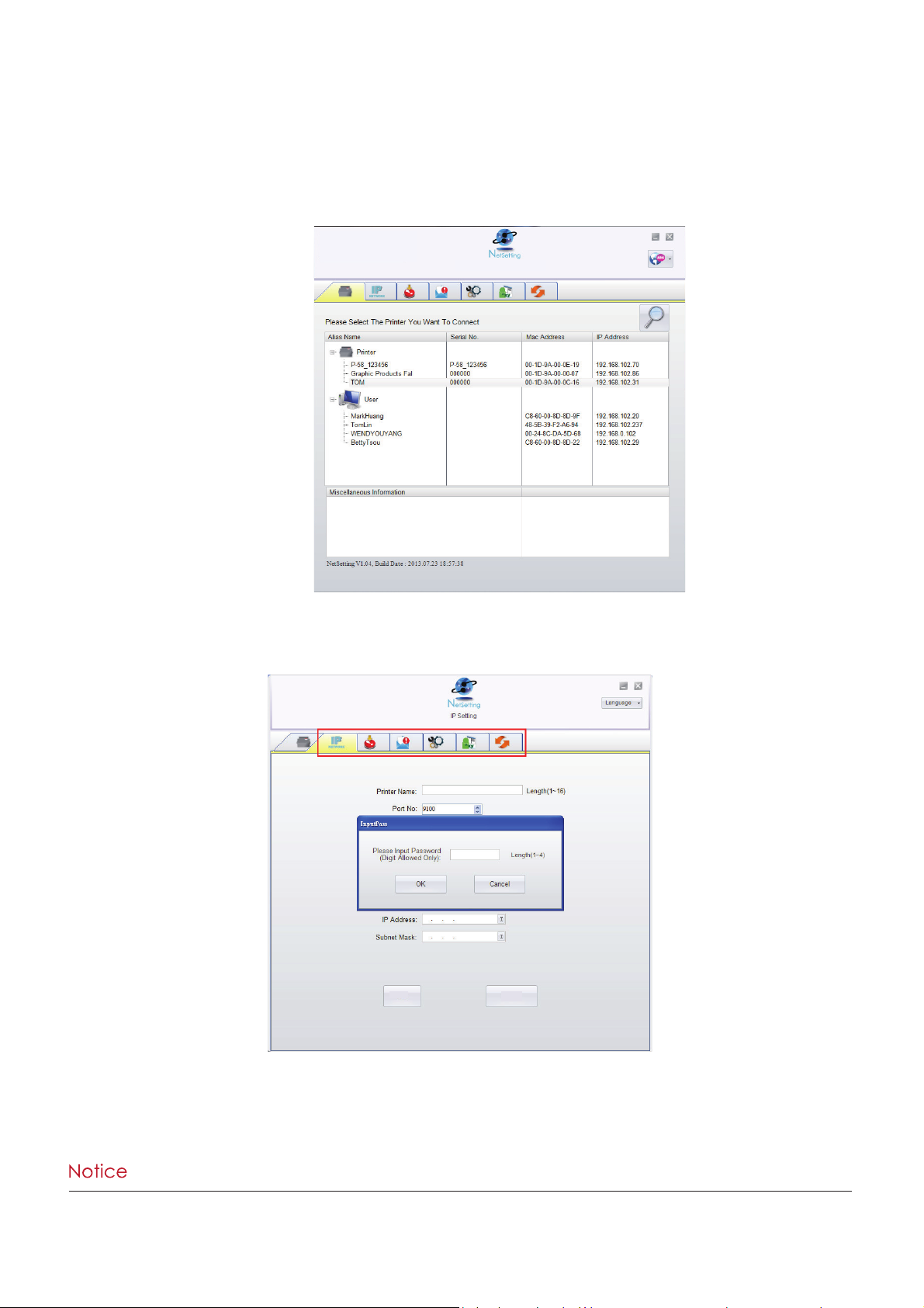
4.2 NetSetting Interface
Doubleclick on the NetSetting icon to start the program.
You will see the start page below. The start page will display the basic information of any connected printer and your PC.
There are six tabs on the top of interface which are used to access different network configuration settings.
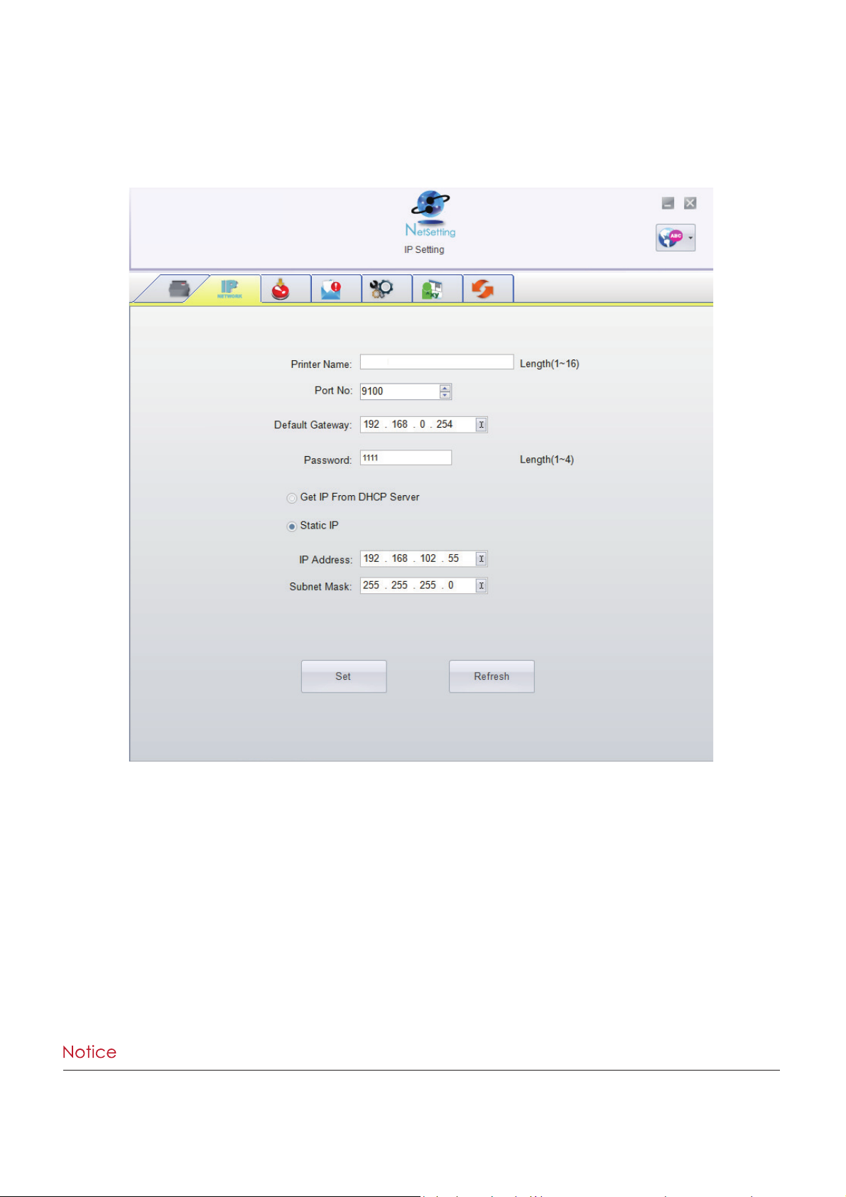
You will need to enter a password to enter the configuration pages.
Click on the magnifying glass icon to search your network for Tharo Ethernet printers.
Any printers that are detected are listed on the start page.
**** The default password is “1111”. You can change the password from the “IP Setting” tab.
ZX1200
Set
Refresh
34
Page 39
4 NetSetting for Ethernet
**** To fully benefit from the NetSetting software, you should be familiar with basic networking principles.
Please contact your network administrator for the required related network settings.
Click the “Set” button to apply the settings and the “Refresh” button to re-query the printer and refresh the values.
IP Setting
On the IP Setting tab you can change the Printer Name, Port Number, Default Gateway and Password.
You can also set the printer’s IP address either by DHCP or by Static IP.
35
Page 40
4 NetSetting for Ethernet
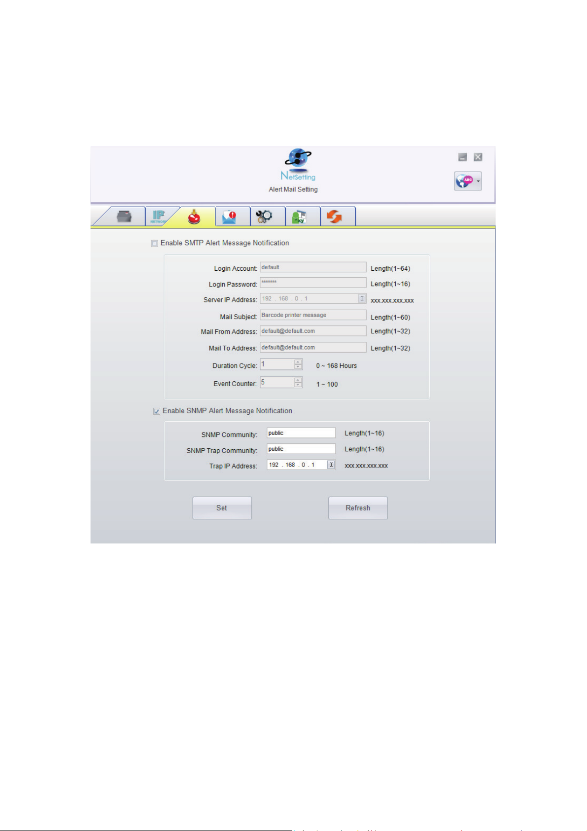
Click the “Set” button to apply the settings and the “Refresh” button to re-query the printer and refresh the values.
Alert Mail Setting
The Printer can send the alert messages to a designated mail account when errors occur. The alert
messages are sent by SMTP (Simple Mail Transfer Protocol) or SNMP (Simple Network Management Protocol).
You can set or change the configurations of SMTP and SNMP on the “Alert Mail Setting” tab.
36
Page 41
4 NetSetting for Ethernet
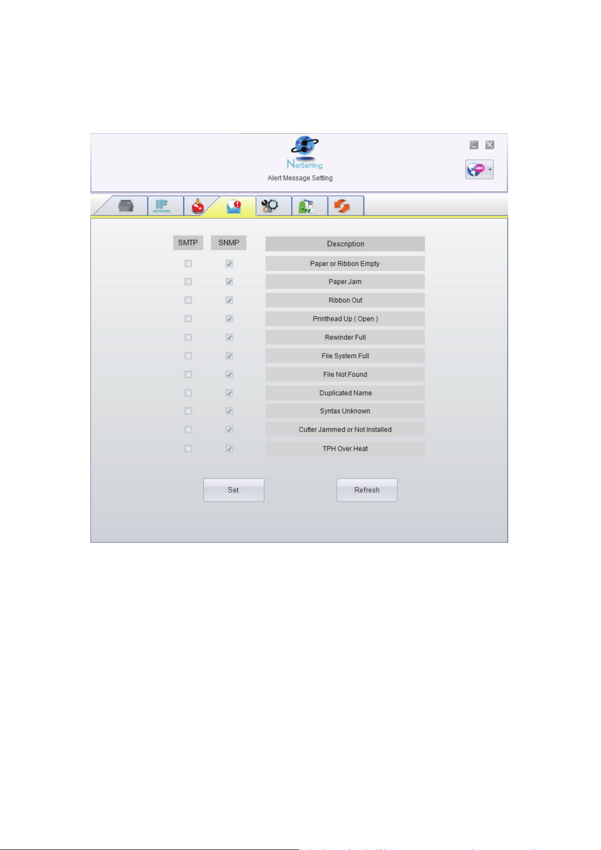
Alert Message Setting
Here you can specify which errors should trigger sending an email. The alert messages can be sent by SMTP, SNMP or both.
Click the “Set” button to apply the settings and the “Refresh” button to re-query the printer and refresh the values.
37
Page 42
4 NetSetting for Ethernet
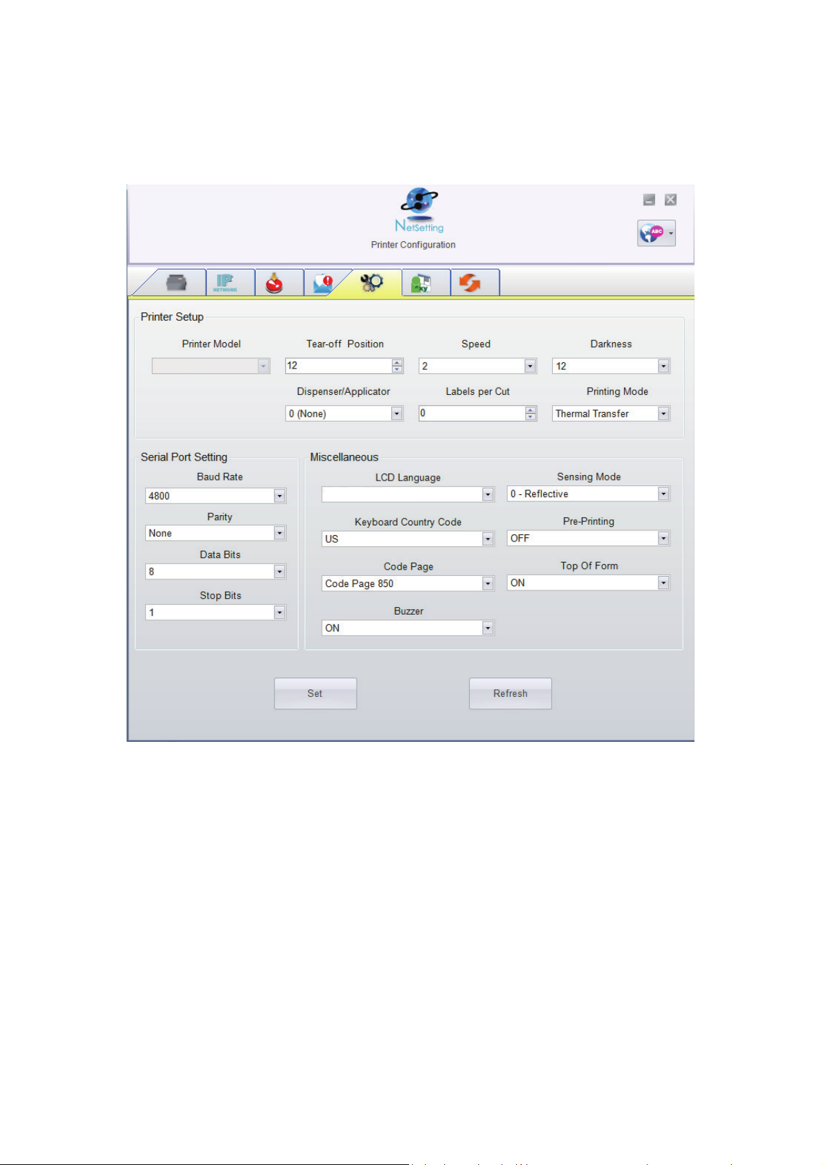
Printer Configuration
This tab allows you to change the configuration of the connected printer. Many of the printer settings can be modified
on this setting page.
ZX1200i
Click the “Set” button to apply the settings and the “Refresh” button to re-query the printer and refresh the values.
English
T-4210
38
Page 43
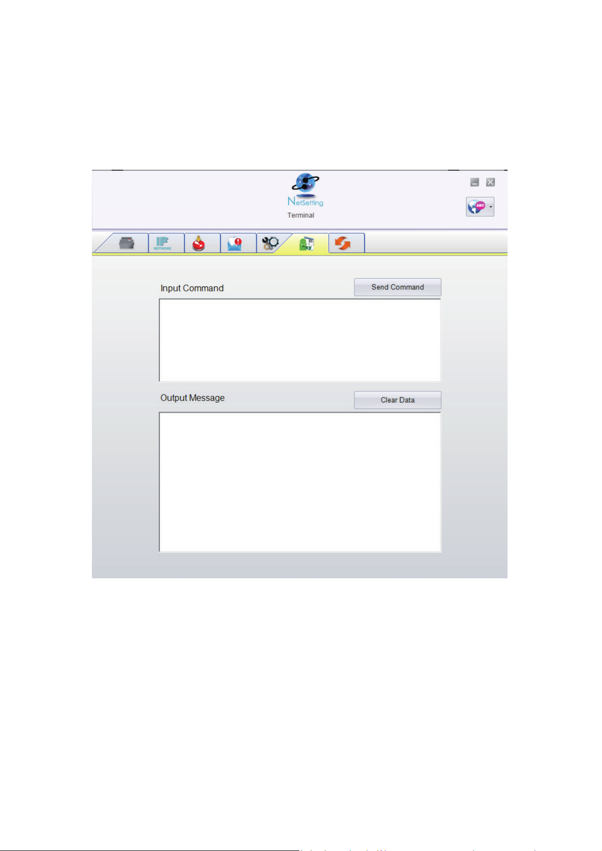
4 NetSetting for Ethernet
Terminal
The “Terminal” tab provides a communication interface for operator to control the printer. Enter printer
commands into the "Input Command" window and press the “Send Command” button, the commands
will be sent to the printer.
For the commands that return a response message, the message will be displayed in "Output Message" window.
Click on the “Clear Data” button to clear these messages.
39
Page 44
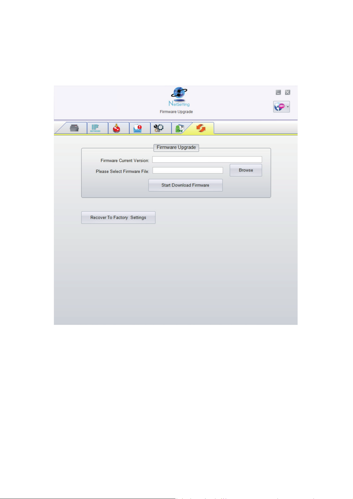
4 NetSetting for Ethernet
In addition to the firmware update, you can click the “Recover To Factory Settings” button to restore all of the printer
configuration settings back to factory default.
Firmware Upgrade
The current printer firmware version is shown on the “Firmware Upgrade” tab. You may also upgrade the printer firmware
from this screen. Simply click the “browse” button and specify the firmware file location.
Then click the “Start Download Firmware” button. The printer firmware will be updated remotely.
BOOT : 1.000a1 F/W : ZX1200i 1.000a
40
Page 45
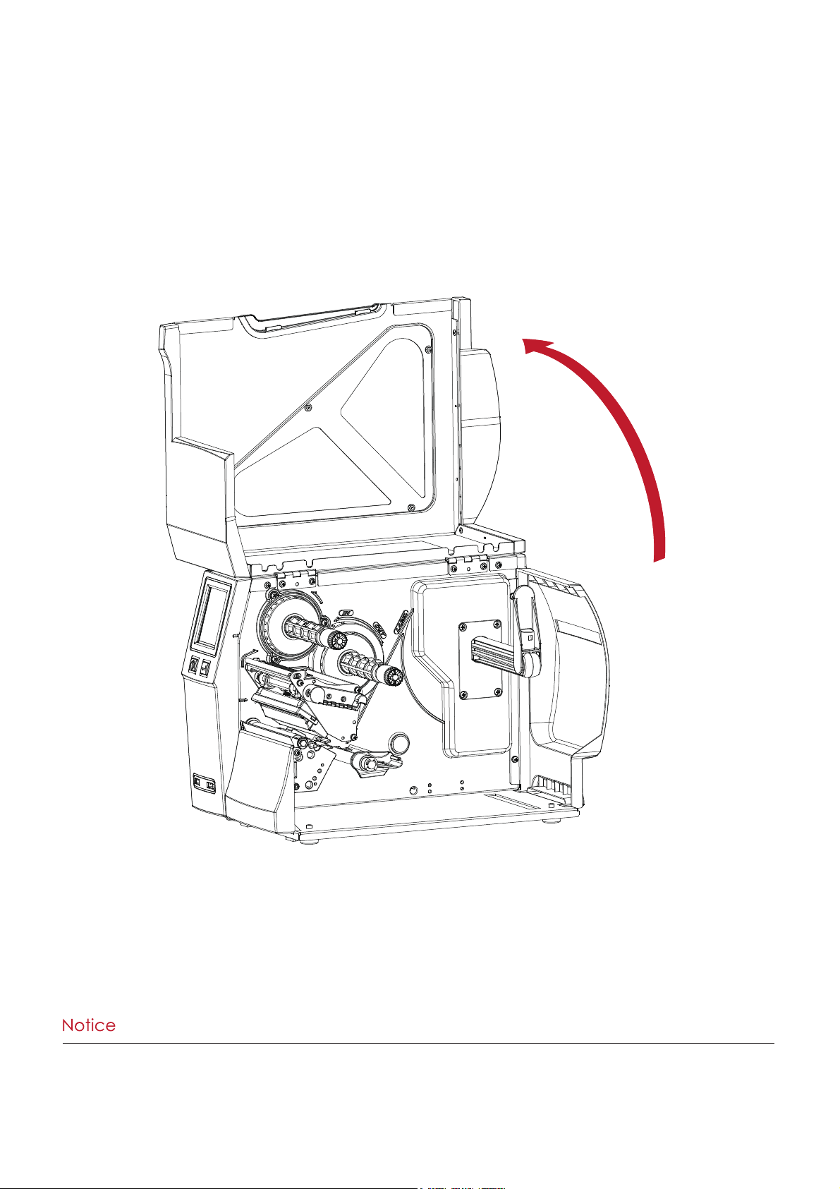
5 Accessories5 Accessories
5.1 Preparation
Before installing any of the optional accessory modules:
1. Turn off the printer and unplug the power cord
2. Open the top cover
**** Remember to switch off the printer before installing the cutter.
**
** Do not use to cut adhesive labels! Glue residue will be left on the cutter blade and impair proper operation.
***
* The cutter can perform 300000 cuts of heavy paper up to 250 μm thick or 100000 cuts of plastic sheet up to 300 μm thick.
Place the printer on a flat surface
and open the printer cover
41
Page 46
5 Accessories
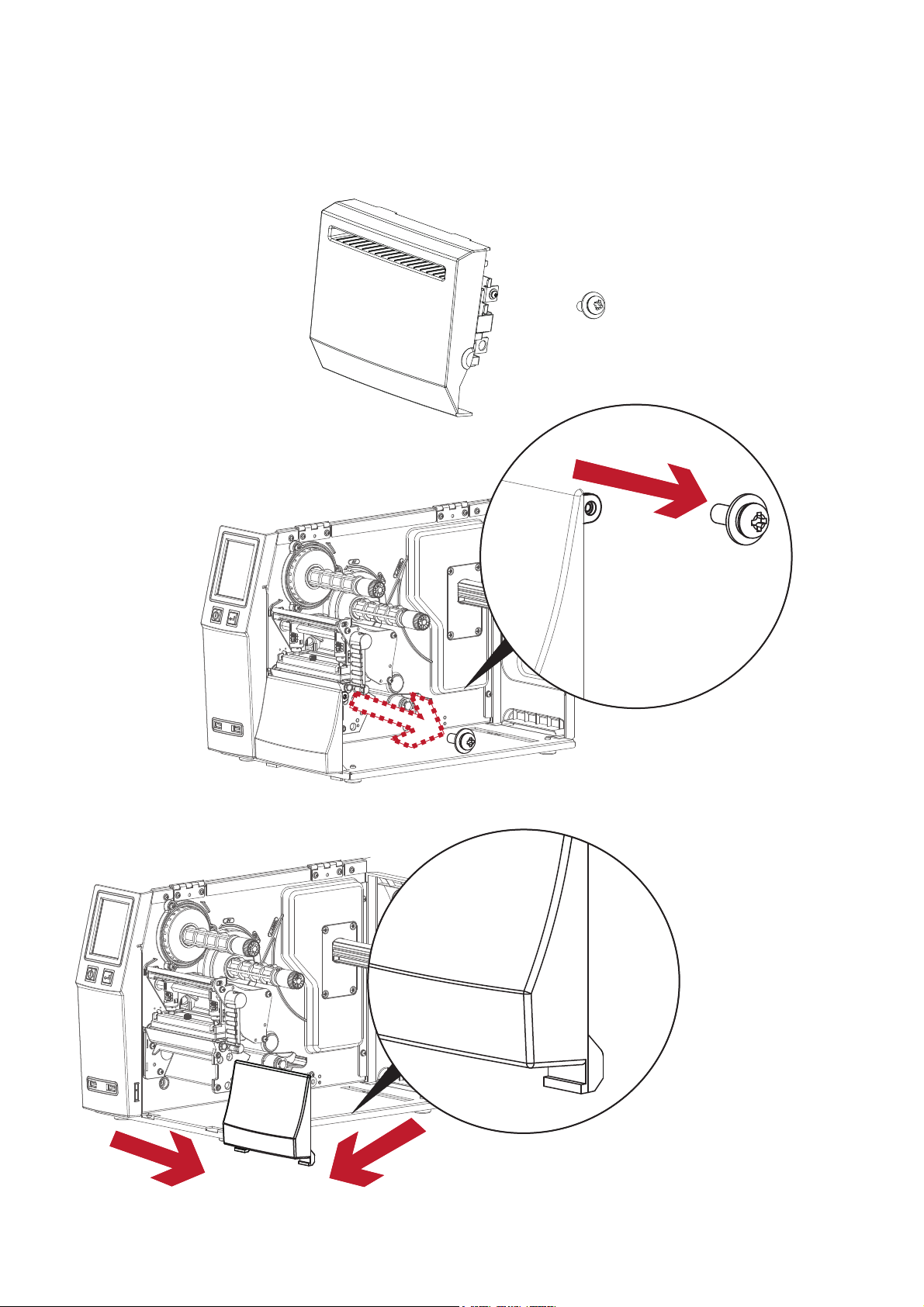
1.Cutter Module
2. Screw
5.2 Installing the Cutter
Cutter Components
Slide the lower cover plate to the right a little bit and
then remove it.
Remove the screw that
secures the lower cover
plate
2
1
42
Page 47
5 Accessories
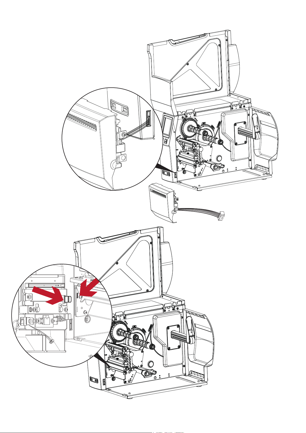
Connect the cutter cable
connector to the cutter jack
on the printer.
Carefully insert the tabs on the cutter
module into the slots on the printer.
(see red arrows)
43
Page 48
5 Accessories
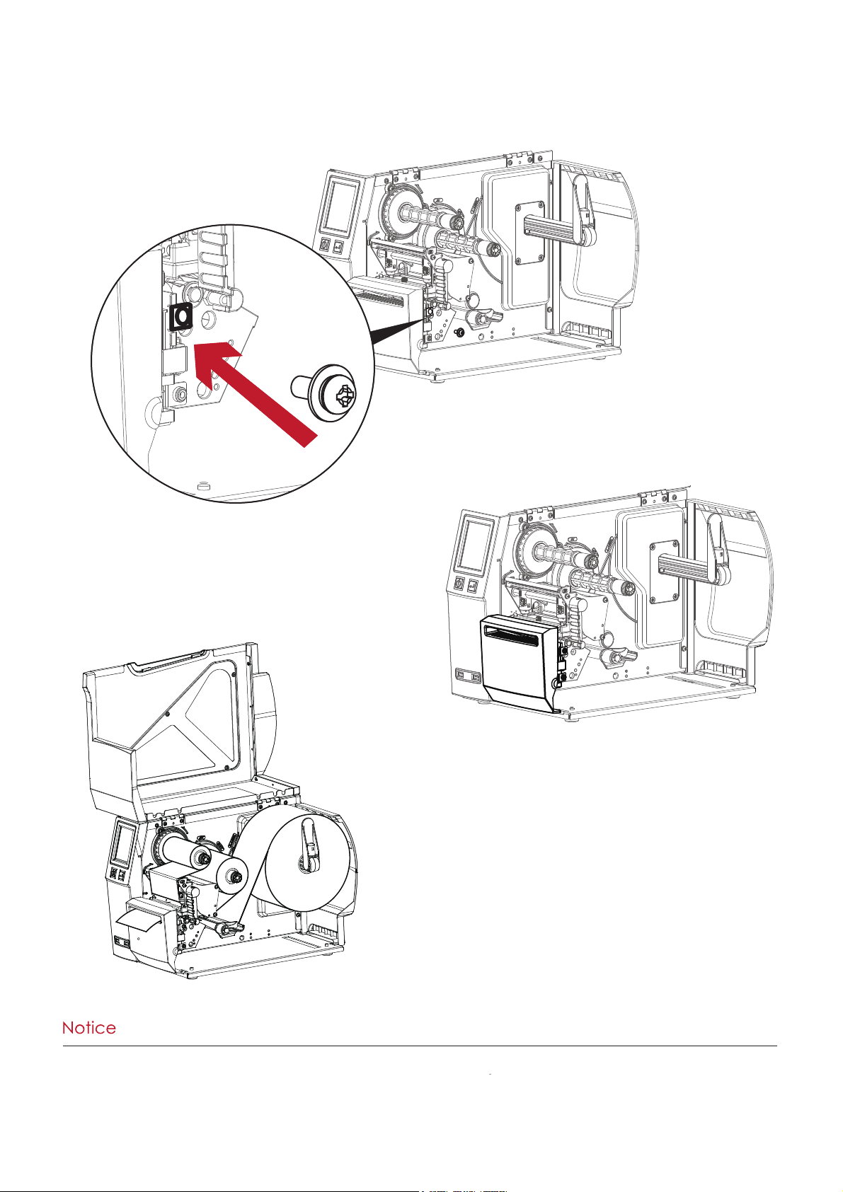
Load a label roll into
the printer and close the
printer cover.
**** Be sure to enable the cutter function is enabled in the printer.(Main--Devices--Option Setting)
**
** For proper cutter operation, the labels should be at least 30 mm high.
***
* After installation of the cutter module, set the stop position (^E) to 30.
The cutter module is now installed.
Secure the cutter module to
the printer housing using the
screws.
44
Page 49
5 Accessories
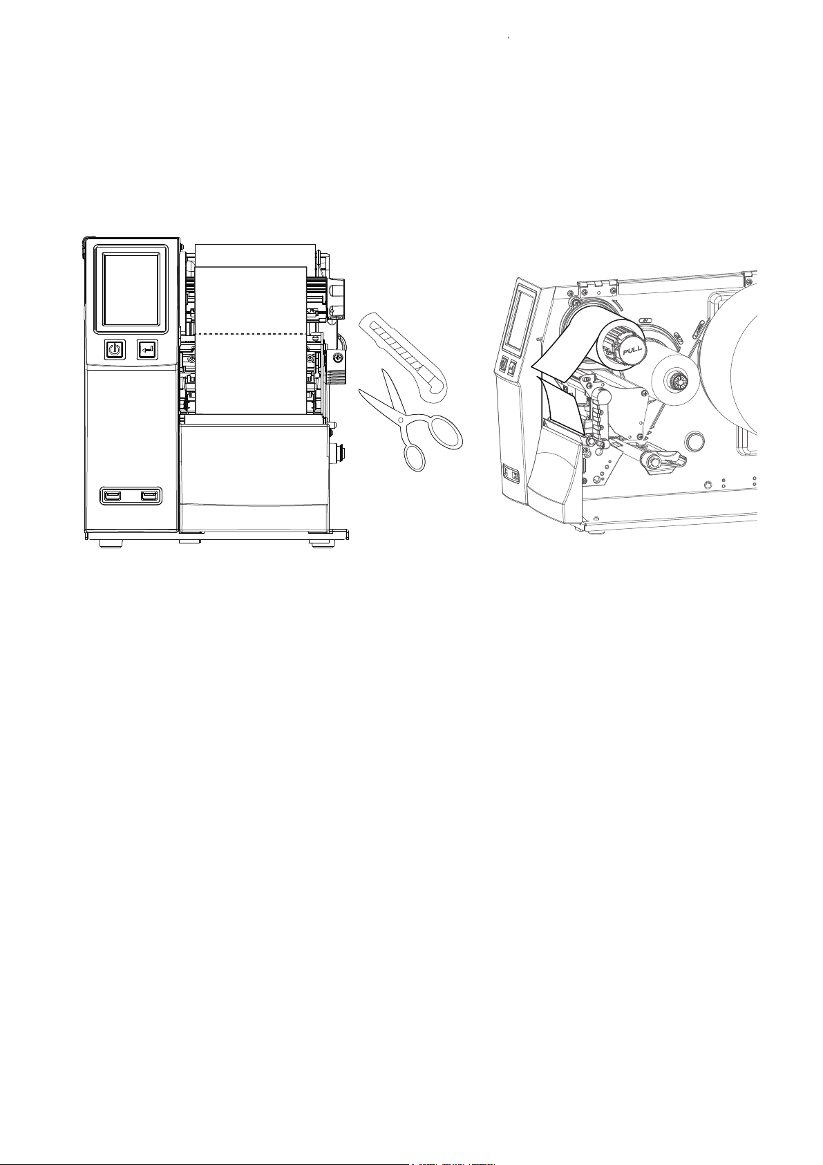
5.3 Ribbon Removal from the Optional Core-free Ribbon Hub
Use a tool to cut off the ribbon.
45
Page 50
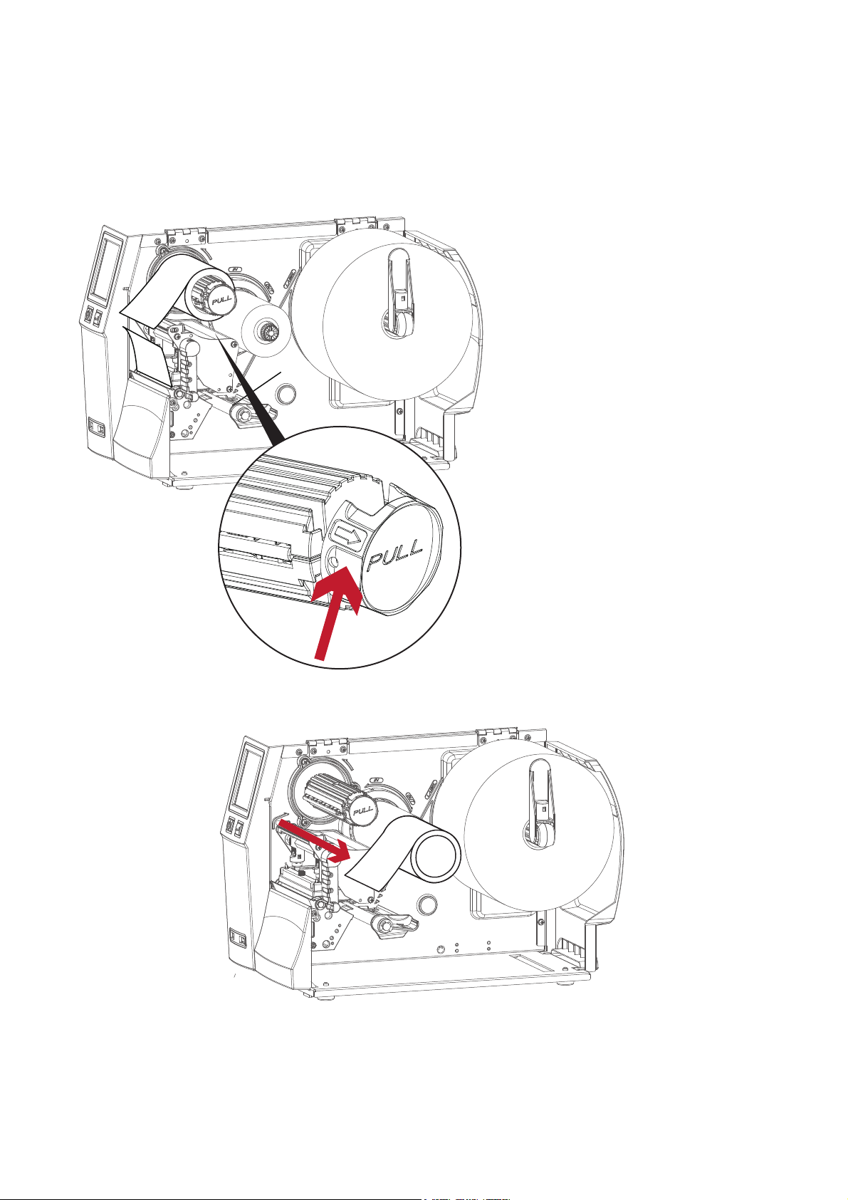
Pull the knob open, the ribbon should be easy to remove.
5 Accessories
46
Page 51
47
5 Accessories
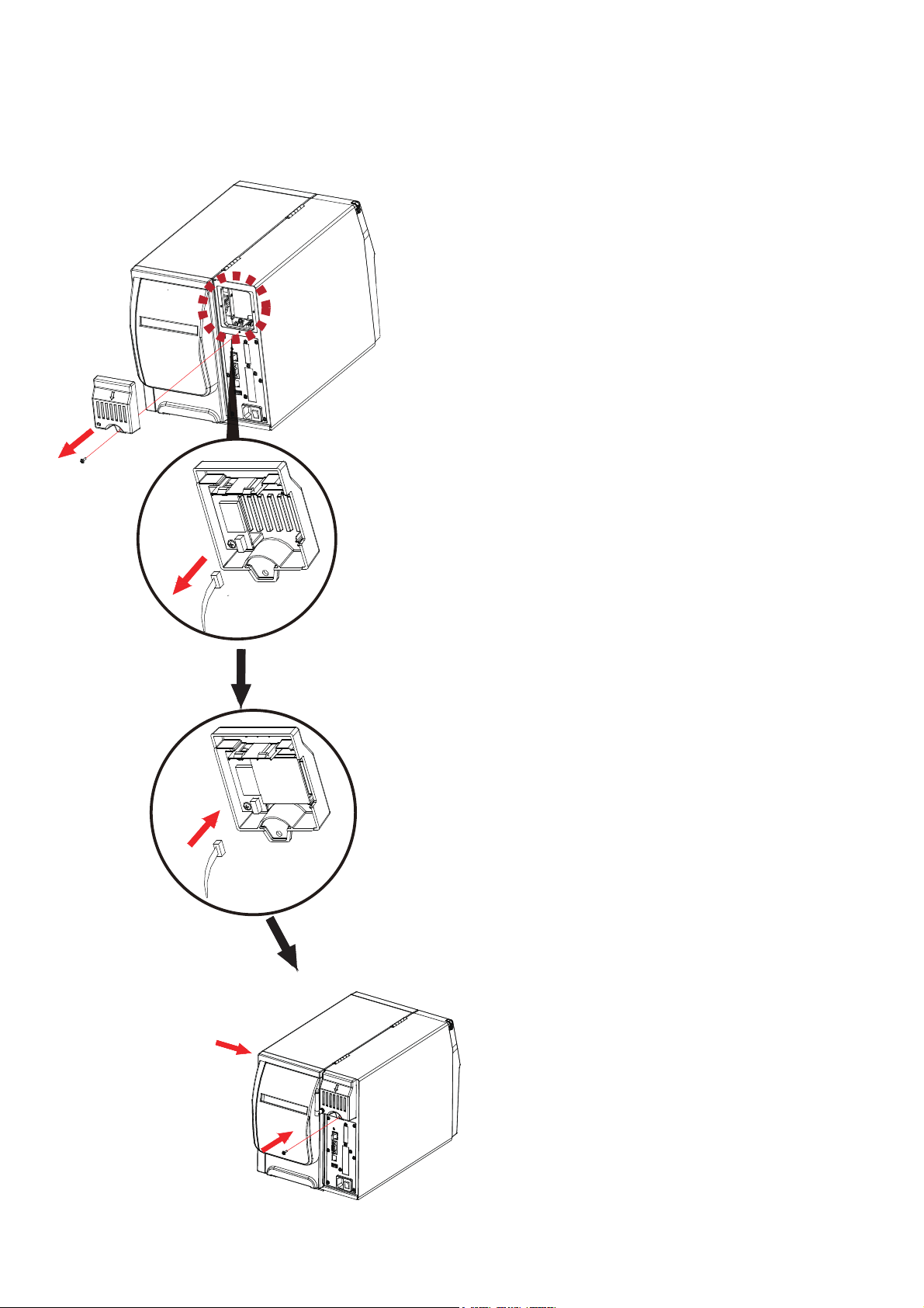
5.4 Installing the WiFi Interface Module
1. Remove the screw
2. Remove the option cover
3. Unplug the connection cable
4. Install the Wifi Module
5. Plug in the connection cable
6. Reinstall the option cover and screw
Page 52
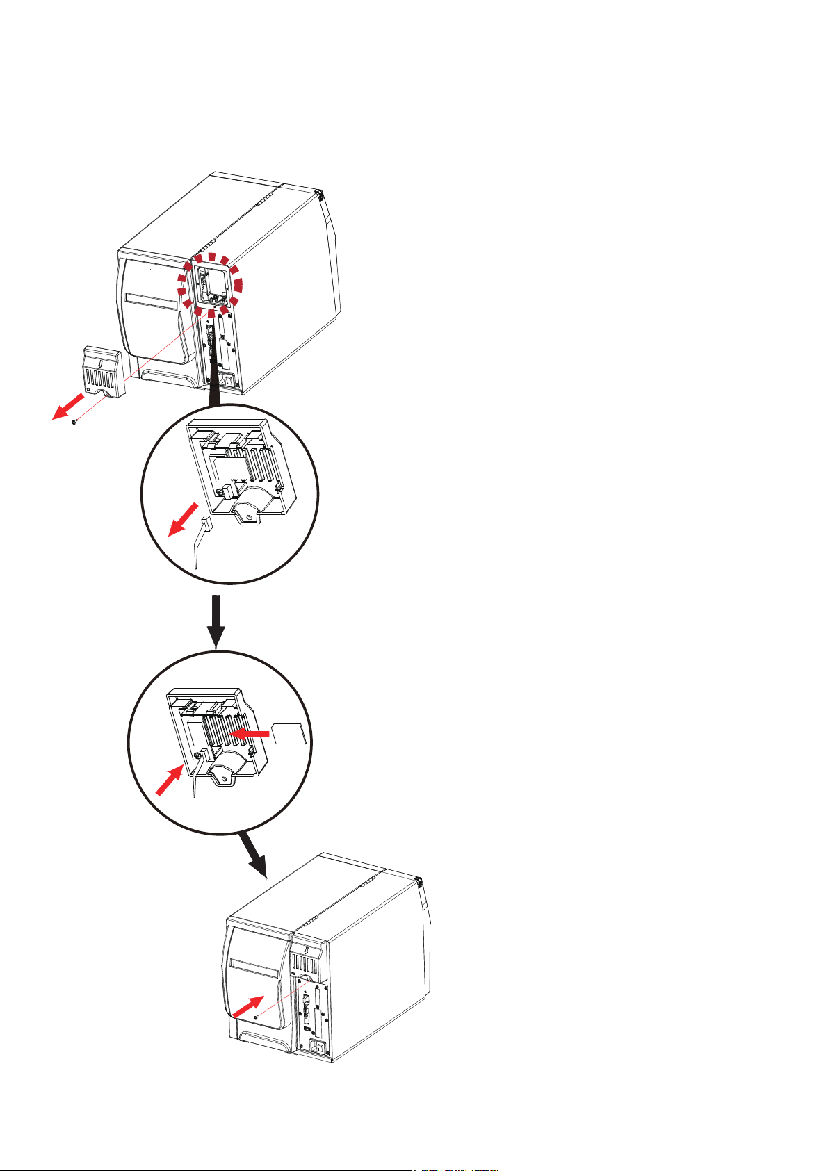
3. Unplug the connection cable
48
5 Accessories
5.5 Installing the Bluetooth Interface Module
4. Insert the Bluetooth Module
6. Reinstall the option cover and screw
5. Plug in the connection cable
2. Remove the option cover
1. Remove the screw
Page 53
6 Maintenance and Adjustment
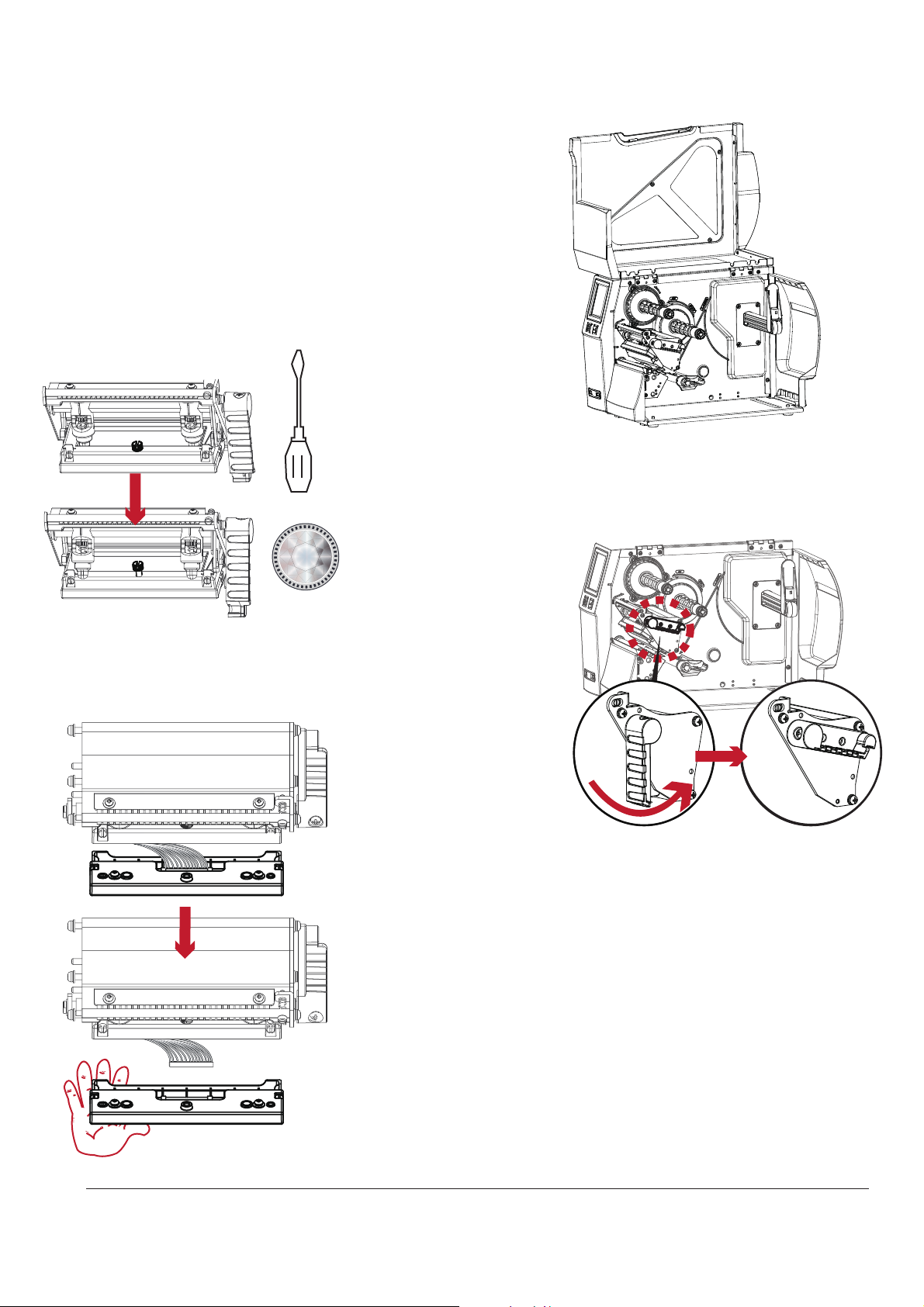
6.1 Removing / Installing the print head module
Open the top cover.
Rotate the print head
release lever
counterclockwise
as shown.
$
Use a screwdriver or a
coin to loosen the TPH
module screw.
Hold the print head module
and gently unplug the TPH cable.
Reverse these steps to install the TPH module
* Remember to switch off the printer before removing the print head module.
1RWH
49
Page 54
6 Maintenance and Adjustment
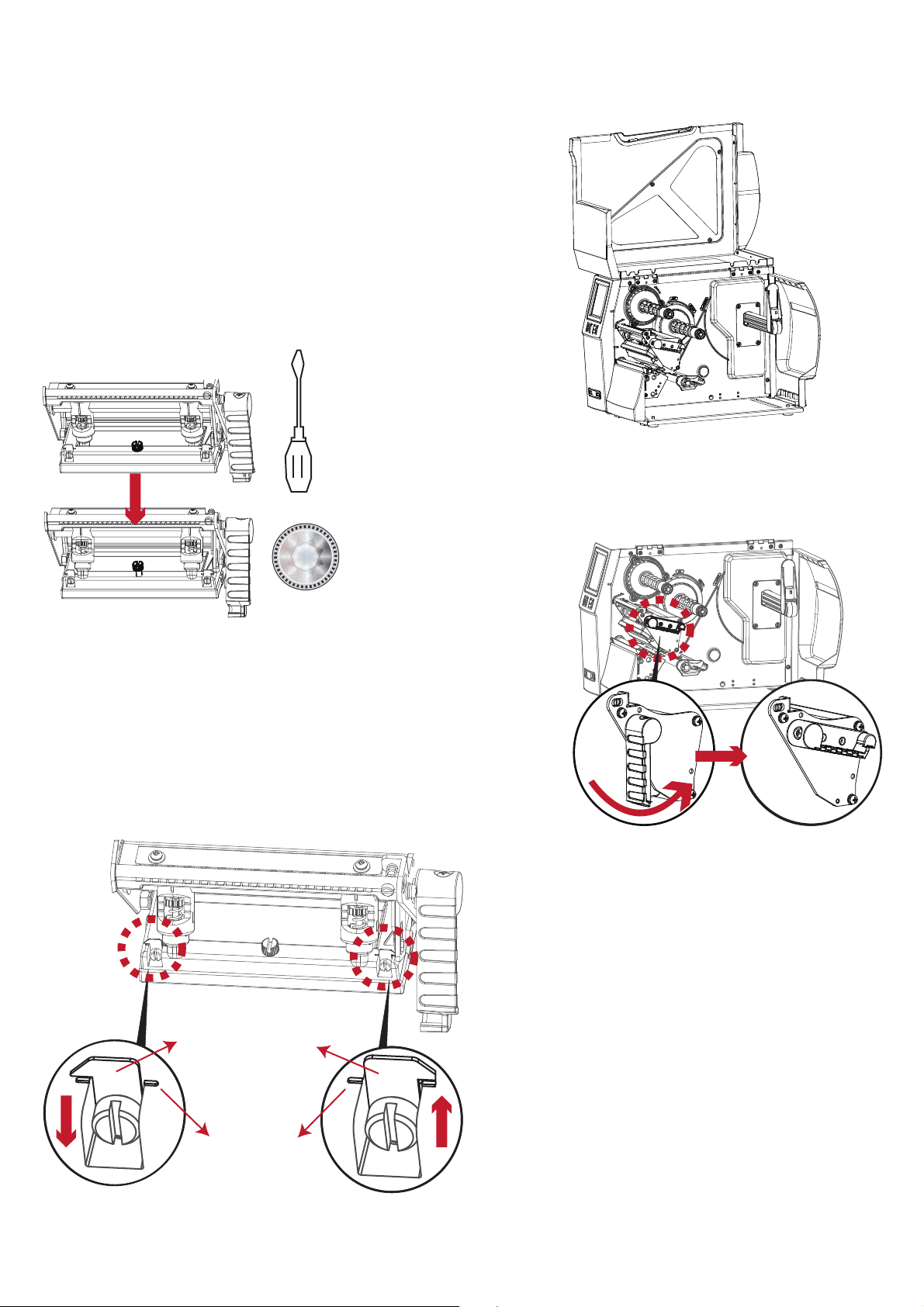
6.2 Adjusting the print line
Open the top cover.
Turn the adjustment screws(A) clockwise
or counterclockwise to align the indicator
with the indicator line.
Repeat the adjustment process until print
quality has improved.
$
indicator line
A A
indicator
Use a screwdriver or a
coin to loosen the TPH
module screw.
Rotate the print head
release lever
counterclockwise
as shown.
50
Page 55
6 Maintenance and Adjustment
6.3 Adjusting ribbon tension
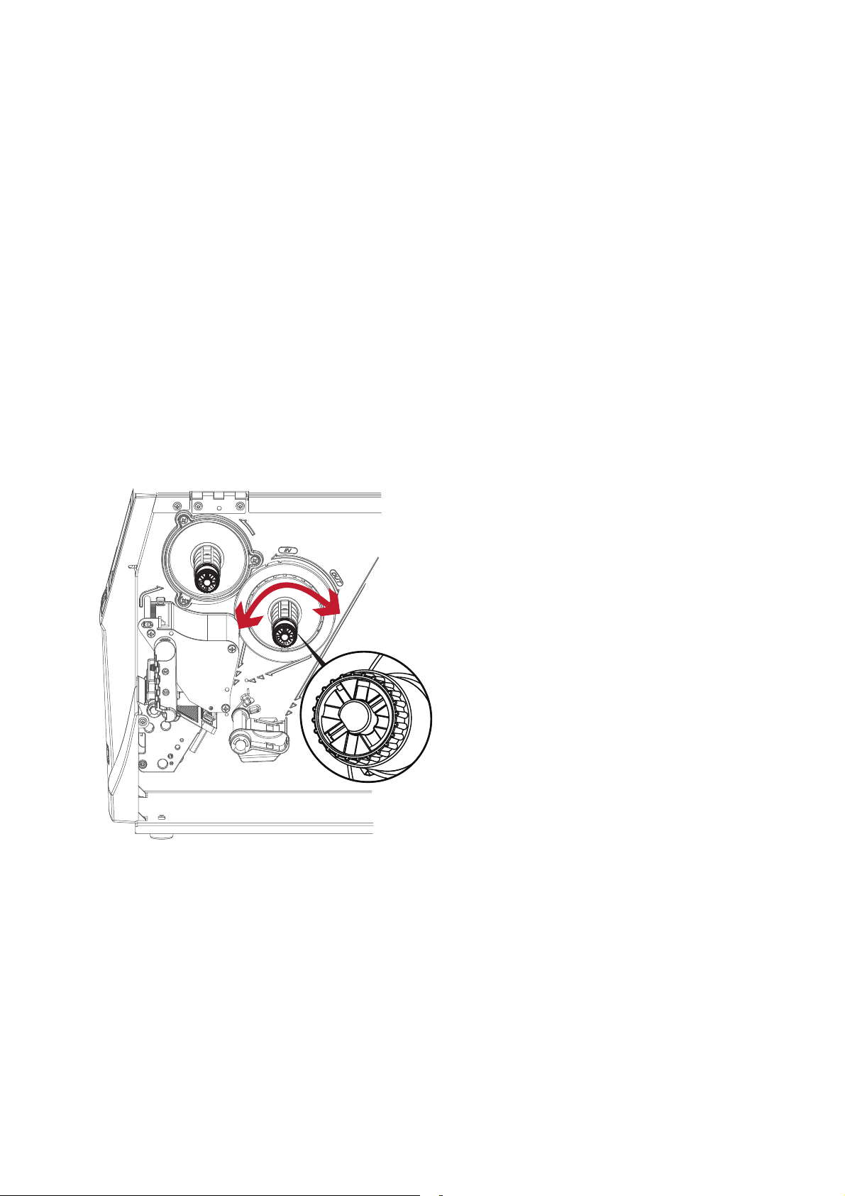
You can adjust the ribbon tension by turning the ribbon shaft knob (see illustration) clockwise or counterclockwise.
There are 4 possible settings marked (1-4) on the ribbon supply hub.
# 1 : Tension is the highest
# 4 : Tension is the lowest
To set the tension, press in the knob and turn it clockwise or counterclockwise as required.
Increasing the tension of the ribbon rewind hub may help remove wrinkling of the ribbon during printing.
For additional details about the wrinkling/creasing of ribbons, see Section 6-6 Ribbon Shield Settings.
If you are using a very narrow ribbon, the printer may not move the label stock forward (particularly with
a ribbon that is less than 2" wide). In that case, reduce the tension by turning the knob of the ribbon supply hub
counterclockwise.
1
1
2
3
4
2
2
3
3
4
4
1
1
1
51
Page 56
6 Maintenance and Adjustment
6.4 Cleaning the thermal print head
Printing labels will cause dirt such as paper dust, particles of ink and label adhesive to
accumulate on the thermal print head. This can cause poor print quality and incomplete
print outs. When this happens, the print head must be cleaned:
1. Turn off the printer.
2. Open the top cover.
3. Remove the ribbon.
4. Release the print head by turning the print head release lever counterclockwise.
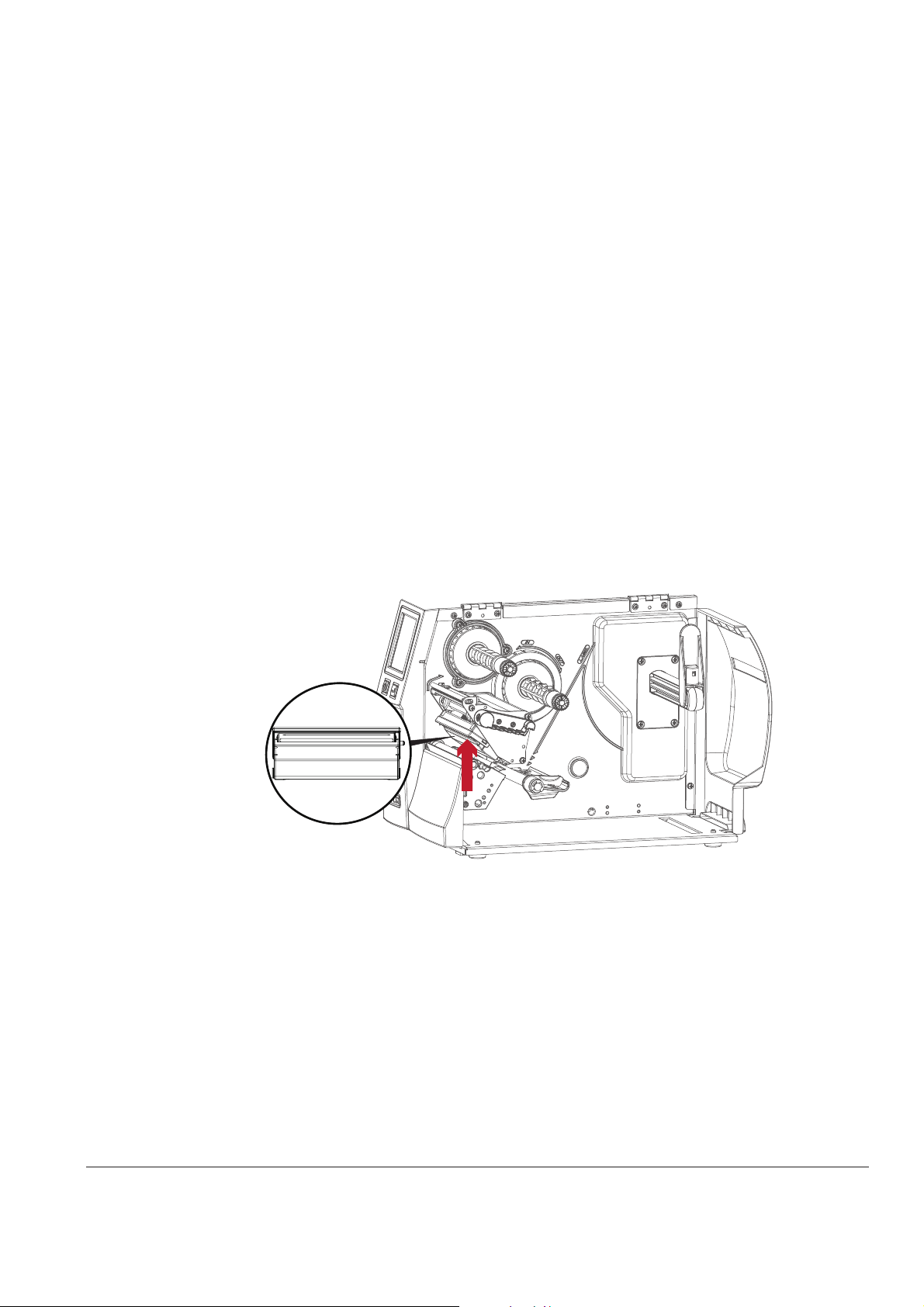
5. Clean the print head surface (see Red arrow) with a special cleaning pen or a
cotton swab soaked in Isopropyl Alcohol.
6. Allow the print head to dry for 2-3 minutes before turning the printer back on.
* The print head should be cleaned once a week or when the print media is changed.
**To help keep the print head clean, the top cover should be closed when printing.
***To ensure print quality and prolong print head life, do NOT use dusty or dirty print media in the printer.
1RWH
52
Page 57
6 Maintenance and Adjustment
6.5 Print head balance and tension adjustment
Open the top cover.
$
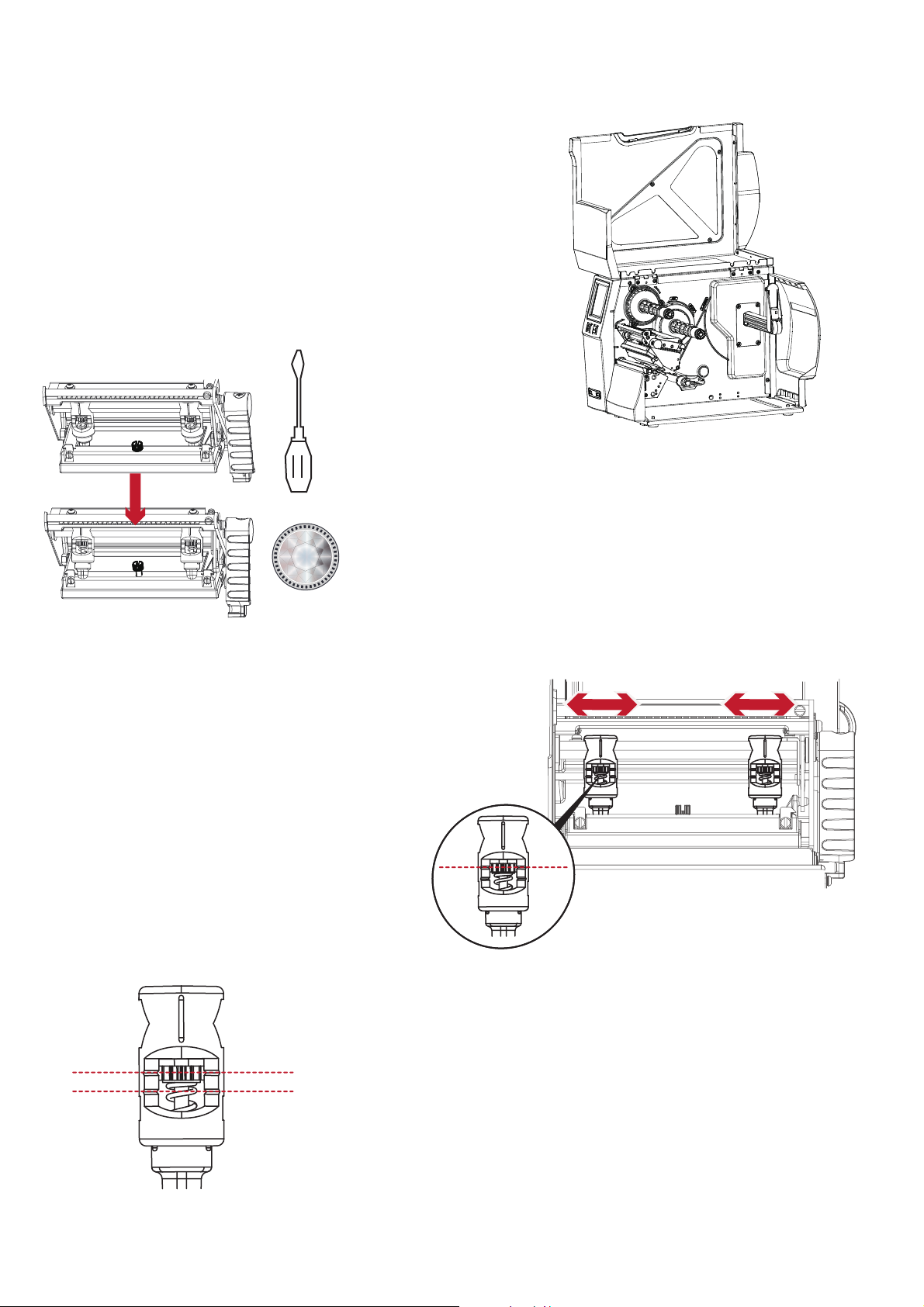
When using a variety of label stock
and ribbons, the ink may not be evenly distributed.
If there is no printed image on one side of the paper
then the print head pressure must be readjusted using
the TPH spring boxes.
Move the TPH spring boxes as shown in the illustration
to change the location of the print head pressure.
The wider the label you are using, the further apart
the TPH spring boxes must be moved away from
each other. If there is no quality improvement,
you need to change the pressure on the TPH spring boxes.
Reset Mark (A)
Turning the screw to the left increases the pressure,
while turning it to the right reduces the pressure.
Be sure not to turn the screw so that it goes below Mark(B).
Mark (B)
Use a screwdriver or a
coin to loosen the TPH
module screw.
53
Page 58
6 Maintenance and Adjustment
6.6 Ribbon shield adjustment
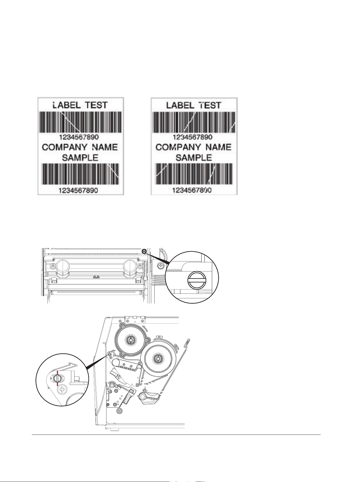
If ribbon wrinkle occurs during printing, adjust the ribbon shield.
If ribbon wrinkle occurs as shown in figure (a), you need to turn ribbon shield screw clockwise.
If ribbon wrinkle occurs as shown in figure (b), you need to turn ribbon shield screw counterclockwise.
(a) (b)
To keep track of the change in print quality, you should adjust the screw by a half turn at a time.
Print a test page. If there is no improvement in the print result, turn the screw by another half turn.
Do not turn the adjustment screw more than two full turns.
* ,I\RXDGMXVWWKHVFUHZE\PRUHWKDQWZRIXOOWXUQVWKHSDSHUPD\QRORQJHUIHHGFRUUHFWO\,QWKDWFDVH
WLJKWHQORRVHQWKHULEERQVKLHOGVFUHZWRDOLJQWKHUHVHWPDUNDQGUHVWDUWWKHDGMXVWPHQWSURFHVV
1RWH
Reset Mark
54
Page 59
6 Maintenance and Adjustment
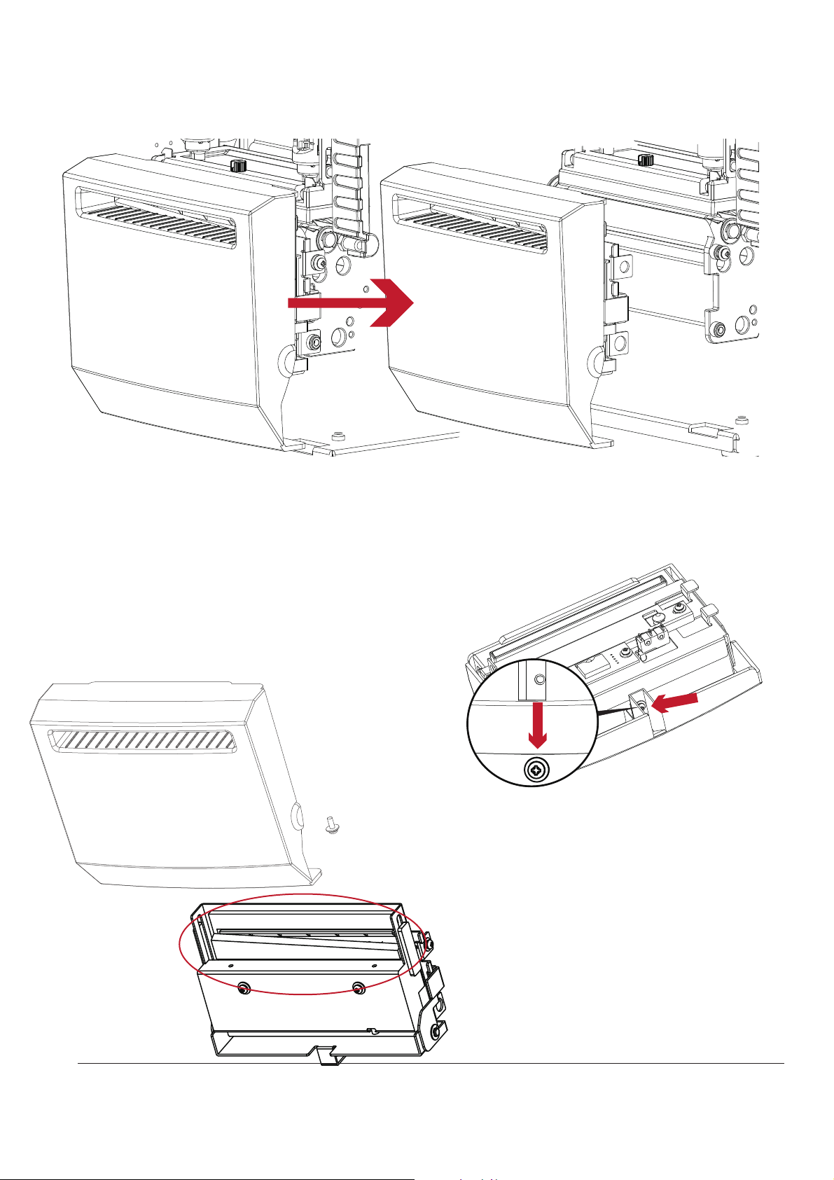
6.7 Cleaning the cutter
* Remember to turn off the printer before removing the cutter
**The labels should be at least 30 mm long to ensure correct functioning of the cutter.
1RWH
Switch off the printer before removing the cutter.
(To remove or install the cutter refer to ‘’accessories’’ in Section 5)
Remove the screw at the
bottom of the cutter .
Remove the cutter cover.
Remove any jammed paper.
Wet a cotton swab with Isopropyl Alcohol and use
it to remove any build ups of adhesive.
Reinstall the cutter on the printer
55
Page 60

♦ Check the power supply.
6 Maintenance and Adjustment
6.8 Troubleshooting
**** If any problems occur that are not described above, please contact your reseller.
Problem
Solution
The printer is switched on but the LED
does not light up.
The LED lights up red and printing has
stopped
♦ Check for software setting or program command errors.
♦ Look for the error in Section 3.3 Error Alerts
♦ Check if the print head mechanism is closed correctly.
The label stock passes through the printer
but no image is printed.
♦ Check that the ribbon is installed with the inked side facing the
label media.
♦ Select the correct printer driver.
♦ Select the correct label stock and print mode.
The label stock jams during printing.
♦ Clear the paper jam.
Check that the print head is clean.
There is no printed image on some parts
of the label.
♦ Check if there is any label or ribbon stuck on the thermal
print head.
♦ Check for errors in the application software.
♦ Check if the starting position has been set correctly
♦ Check the ribbon for wrinkles.
There is no printed image on part of the
label or the image is blurred.
♦ Check the thermal print head for dust or other dirt.
♦ Use the internal “~T” command to perform a Test Print and check if
the print head can print across the entire width.
♦ Check the quality of the print media.
The printed image is positioned
incorrectly.
♦ Check if there is paper or dust covering the label sensor.
♦ Check if the label stock is suitable for use. Contact your reseller.
♦ Check the paper guide.
Skipping labels during printing.
♦ Check the label height setting.
♦ Check if there is dust covering the label sensor.
♦ Perform a label Calibration
The printed image is blurred.
♦ Check the print darkness setting.
♦ Check if the print head is dirty.
The cutter does not cut off the labels in a
straight line.
♦ Check if the label stock is installed correctly.
The cutter does not cut off the labels
completely.
♦ Check if the label thickness exceeds 0.2 mm.
When using the cutter, the labels are not
fed through or are cut off incorrectly.
♦ Check if the cutter has been correctly installed.
♦ Check if the paper guides are sticky.
The label dispenser is not functioning
normally.
♦ Check if there is dust on the label dispenser sensor.
♦ Check if the label stock is installed properly.
1RWH
56
Page 61
APPENDIX
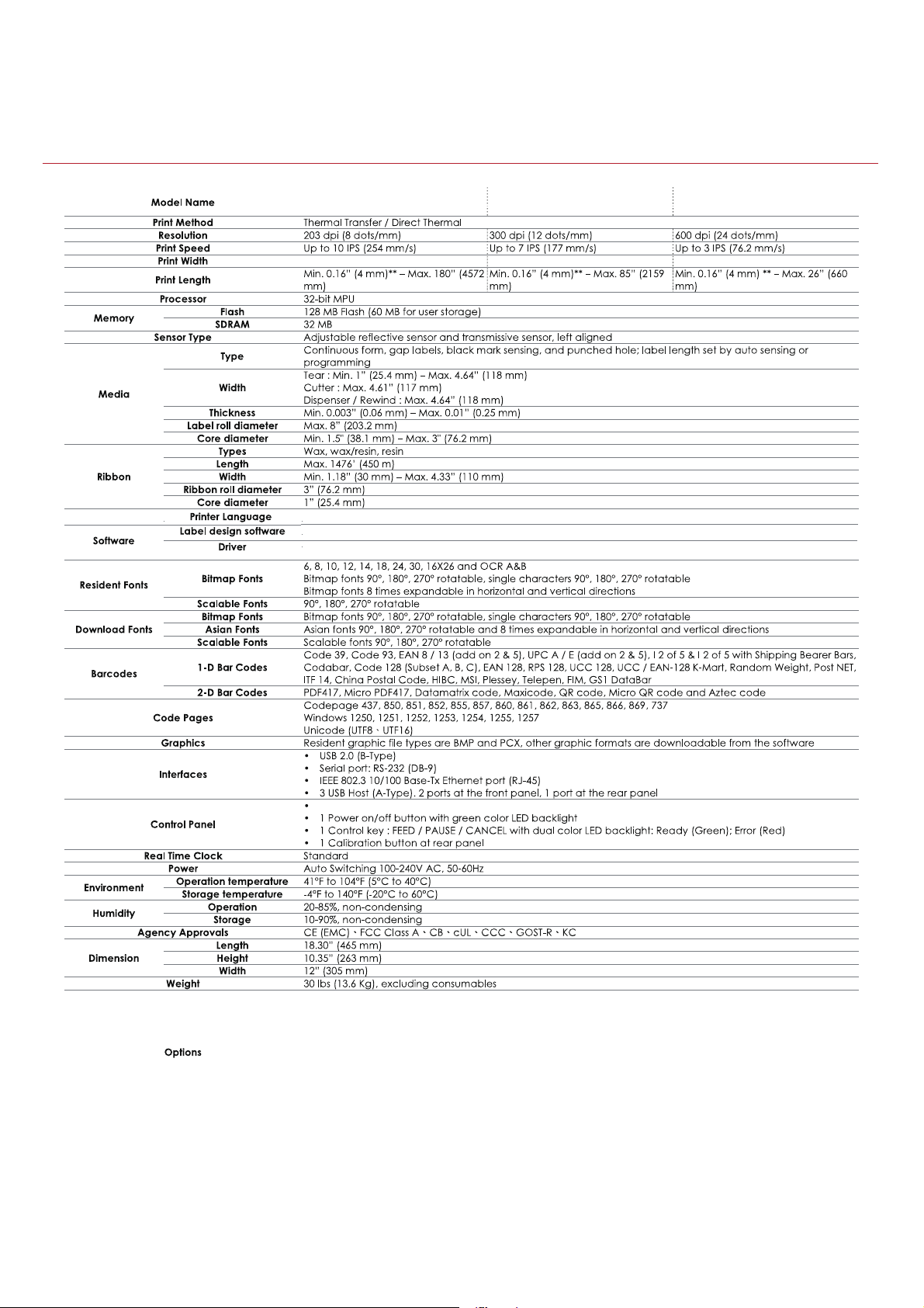
PRODUCT SPECIFICATIONS
Notice
Specifications are subject to change without notice. All company and/or product names are trademarks and/or registered
trademarks of their respective owners.
Cutter Module
Parallel Port Adaptor Module
Bluetooth Module
WiFi Print Server Module (IEEE 802.11b/g/n)
Applicator Interface
External label roll holder for 10” (250mm) O.D. label rolls
External label rewinder
Label Dispenser and Internal Rewinder (factory installed)
Core-free Ribbon Rewind Hub (factory installed)
TPL
EASYLABEL Start
T-4210
T-4307
T-4604
57
Windows and CUPS (Linux and Mac)
4.25” (108mm) 4.16” (105.7mm) 4.16” (105.6mm)
Backlit 3.2” touch screen LCD
Page 62
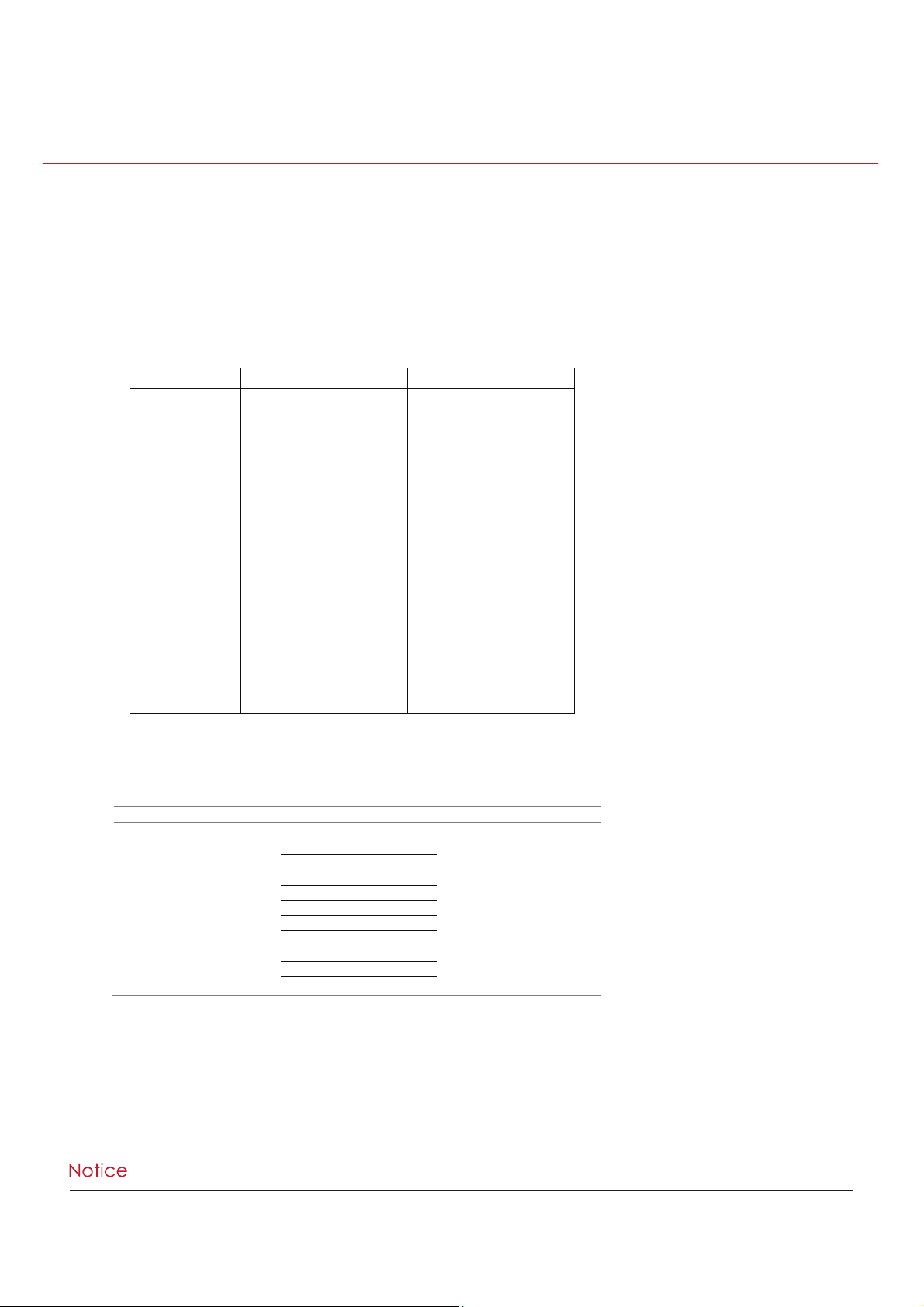
INTERFACE
Serial Port
Default settings烉
Baud rate 9600, no parity, 8 data bits, 1 stop bit, XON/XOFF
protocol and RTS/CTS
RS232 Housing(9-pin to 9-pin)
DB9 Socket
DB9 Plug
-
RXD
TXD
DTR
GND
DSR
RTS
CTS
RI
Computer
1 1
2
2
3
3
4
4
5
5
6
6
7
7
8
8
9
9
+5V, max 500mA
TXD
RXD
N/C
GND
RTS
CTS
RTS
N/C
Printer
****The total current to the serial port may not exceed 500mA.
=
Parallel Port (Optional)
=
Handshaking
:
DSTB is sent to the printer, BUSY to the host computer
Interface
cable
:
Parallel cable compatible with IBM computers
Pinout
:
See below
Pin No.
Function
Transmitter
1
2-9
10
11
12
13
14
15
16
17
18
19-30
31
32
33
34-35
36
/Strobe
Data 0-7
/Acknowledge
Busy
/Paper empty
/Select
/Auto-Linefeed
N/C
Signal Gnd
Chassis Gnd
+5V, max 500mA
Signal Gnd
/Initialize
/Error
Signal Ground
N/C
/Select-in
Computer / printer
Computer
Printer
Printer
Printer
Printer
Computer / printer
Computer
Computer / printer
Printer
Computer / printer
58
APPENDIX
INTERFACE
Page 63

Pin NO. 1 2 3 4
Function
VBUS
D-
D+
GND
86%3RUW
=
Computer Connector: Type A
Pin NO. 1 2 3 4
Function
VBUS
D-
D+
GND
Connector Type: Type B
(WKHUQHW3RUW5-
=
PIN NO.
FUNCTION
1
T+
2
T-
3
R+
4
N/C
5
N/C
6
R-
7
N/C
8
N/C
$SSOLFDWRU3RUW2SWLRQDO
=
PIN NO.
FUNCTION
1
GND
2
+5V,max 500mA
3
START_PNT
4
SLEW_LABEL
5
PAUSE
6
REPRINT
7
+24V,max 1.5A
8
GND
9
RIBBON_LOW
10
SERV_REQ
11
END_PRINT
12
MEDIA_OUT
13
RIBBON_OUT
14
DATA_READY
15
OPT_FAULT
APPENDIX
INTERFACE
59
 Loading...