

Page 1

Thalheimer
Transformatorenwerke GmbH
Operating instructions
Variable isolating transformers
LTS 602
LTS 604
LTS 606
Thalheimer Transformatorenwerke GmbH, Jägerstraße 8, 09380 Thalheim, BRD
E-mail: info@thalheimer-trafowerke.com, Internet: www.thalheimer-trafowerke.com
Phon: +49(0) 3721 86 265 / 86 290, Fax: +49(0) 3721 86 400
Page 2
Field of application
Variable isolating transformers are portable devices which are arranged
in 19” housings. These variable and low- resistance a.c. voltage sources
can be used in all fields, especially in workshops, laboratories, test stands
and service shops. Due to the galvanic separation between the primary
and the secondary by means of a test voltage of 3,5 kV and the
construction according to the protective system II these transformers
are especially suitable for use electric workshops, where they are
employed for protective isolation of electric or electronic devices which
are in need of repair. They are useable only in dry rooms.
The output voltage ca be easily adjusted between 1 V and 250 V by
means of the adjustable transformer. In continuous operation, the
transformer can be subjected to maximum current loading throughout
the whole adjusting range.
The most apparent advantage of such a voltage control are the
maintenance of the output voltage curve, the nealy loss-free voltage or
adaption of current and the relatively low internal resistance.
Operating instructions
The transformers can be used either individually or in combination with
other devices in measuring places or laboratories. Take care to ensure
that they are vented through the ventilating ducts available. The ambirent
temperature should not increase over 40
o
C.
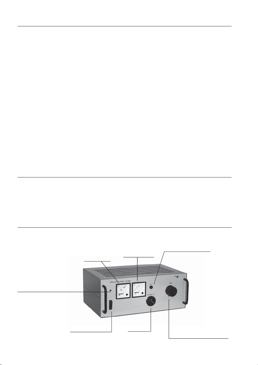
Variable isolating transformer LTS
voltmeter
mains signal lamp
mains switch
ampmeter
socket
- 2 -
secondary fuse
adjusting knob of
output voltage
Page 3

After connection to a mains of 230V (or 110V), 50/60 Hz, the transformer
can be put into operation with the aid of the main switch. The mains
signal lamp light in the ON state. Switching- on causes a current surge
in the mains which may be sufficient to release automatic cut outs.
Therefore, we recommend to use slow- blow fuses in the mains.
When the knob is turned in clockwise direction, the voltage supplied
by the socket is increased. This voltage is simultaneously indicated by
the voltmeter.
Caution!
Only one consumer at a time my be connected to the transformer. It is
not permitted to connect several consumers by making use of a
distributor. In case of a defective consumer, the earth potential would
be fed to other connected devices as well. Thus, the output voltage
would nolonger be free from potential.
Repairs
All repairs will be carried out by the after sales service of the manufacturer.
Maintenance
At certain intervals free the sliding path of the adjustable transformer
from dust, using a cloth soaked with spirit.
Never use oil.
Access to the sliding path of the adjustable transformer is obtained by
removing the four screws and the cover plate of the housing.
Caution!
Disconnect the device from the mains before removing the screws.
Storage conditions
Store packed and unpacked devices only in closed rooms and under
the climatic conditions specified for their use. The storage rooms must
be as free from dust as possible and also free from acid and caistic
vapours as well as gases, which have a corrosive action.
Transport conditions
The device may be transported in packed condition only. For this, use
the original package only or a similar package. The consignee is
requested to store the device immediately in rooms with respective
climatic conditions.
Do not store more than three devices one upon the other.
- 3 -
Page 4

Technical data
Type LTS 602 LTS 604 LTS 606
rated input V 230 (110) 230 (110) 230 (110)
input current amps 2.3 (4.6) 5.5 (11) 8 (16)
max. power VA 400 1000 1600
rated frequency Hz 50/60 50/60 50/60
no- load power loss W <25 <40 <60
output voltage V 1...250 1...250 1...250
tolerance of output voltage
no load V +25 +25 +25
rated load V -15 -15 -15
turn to turn voltage V <0,4 <0,5 <0,8
output current amps 1,6 4 6
mode of operation continuous operation
degree of protection II II II
protective system IP 20 IP 20 IP 20
protective measure pretective insulation
test voltage
pri.-sec. kV 3,5 3,5 3,5
pri., sec.-housing kV 3,5 3,5 3,5
temp. resistance class B B B
max. ambient temp.oC +40 +40 +40
temp. range
o
C -10 ... +40 -10 ... +40 -10 ... +40
relative humidity % 80 at + 35 oC 80 at + 35 oC 80 at + 35 oC
shock sequence test 800 shocks with 15 g
weight kg 12 18 24
dimensions
width mm 452 452 452
height mm 146 190 190
dept mm 252 312 312
The conditions for temperature, humidity and shock for operation are
the same for storage and transport.
- 4 -
Page 5

Circuit diagrams
Variable isolating transformer LTS 602
Variable isolating transformer LTS 604
Variable isolating transformer LTS 606
- 5 -
 Loading...