

Page 1
Thales SureLINK IP Handset
User Guide
This document contains technology controlled for export by the U.S. Department of Commerce in
accordance with Export Administration Regulations. Diversion contrary to U.S. law prohibited.
JULY 2019
COPYRIGHT © 2019
THALES DEFENSE & SECURITY, INC.
ALL RIGHTS RESERVED
F
User Manual PN 84481 Rev 1
i
Page 2
Rev
Date
Description of Change
Author
Rev 1
July 2019
Initial Release
SJacques
WARNING – INFORMATION SUBJECT TO EXPORT CONTROL RESTRICTIONS
This document contains technology controlled for export by the U.S. Department of
Commerce in accordance with Export Administration Regulations (EAR). Diversion contrary
to U.S. law prohibited. Include this notice with any reproduced portion of this document.
WARNING – INFORMATION SUBJECT TO EXPORT CONTROL RESTRICTIONS
This document contains technology controlled for export by the U.S. Department of
Commerce in accordance with Export Administration Regulations (EAR). Diversion contrary
to U.S. law prohibited. Include this notice with any reproduced portion of this document.
WARNING – INFORMATION SUBJECT TO EXPORT CONTROL RESTRICTIONS
This document contains technology controlled for export by the U.S. Department of
Commerce in accordance with Export Administration Regulations (EAR). Diversion contrary
to U.S. law prohibited. Include this notice with any reproduced portion of this document.
WARNING – INFORMATION SUBJECT TO EXPORT CONTROL RESTRICTIONS
This document contains technology controlled for export by the U.S. Department of
Commerce in accordance with Export Administration Regulations (EAR). Diversion contrary
to U.S. law prohibited. Include this notice with any reproduced portion of this document.
RECORD OF CHANGES
User Manual PN 84481 Rev 1
ii
Page 3

Export Compliance:
This product is controlled by the export laws and regulations of the United States of America. The U.S. Government may restrict the
export or re-export of this product to certain individuals and/or destinations. For further information, contact the U.S. Department of
Commerce, Bureau of Industry and Security.
This product User shall comply with all applicable laws related to export and import of this product in any jurisdiction and/or
government authority. User shall be responsible for complying with any and all export and import restrictions, laws and regulations in
any country User is conducting business.
Disclaimer:
This manual contains information that is current as of the date shown on the front cover. Every effort has been made to ensure the
correctness and completeness of the material in this document. The information in this document is subject to change without notice.
Thales®, Thales MissionLINK®, and any other Thales trademark or Thales service mark referred to or displayed in this document are
trademarks or registered trademarks of Thales.
Legal Notices
This product is subject to a Limited Warranty, Limitations, Exclusions, and Terms and Conditions, which can be found on line at
www.thalesdsi.com.
Prior to Installing this product, read and understand this Installation Guide and the User Manual, including the safety warnings and
information. Failure to do so could result in serious injury or death.
Intellectual Property
User acknowledges that the Products
Thales and others. No title to or ownership of any proprietary rights related to any Product is transferred to User or any Customer
pursuant to the use of this product. The purchase of any Thales products shall not be deemed to grant either directly or by implication
or otherwise, any license under copyrights, patents, or patent applications of Thales or any third party software providers, except for
the normal, nonexclusive, royalty free license to use that arises by operation of law in the sale of a product.
C o nt e nt C op y ri g ht
User is exclusively responsible for the use of this product, including proper use of third party copyrighted materials. If the User violates
these terms, the User agrees to defend, indemnify and hold Thales harmless with respect to any claims or actions by third parties
related to the improper use of copyrighted material and to pay all costs, damages, fines and other amounts incurred by Thales, or on
its behalf, in the defense of any such claims or actions.
I n de m ni t y
User agrees to defend, indemnify and hold Thales harmless with respect to any claims or actions by any governmental entities or other
third parties related to any violation of law with use of the Product or Accessories, misuse of the Product or Accessories under these
Terms and Conditions, or any other violation of these Terms and Conditions and further agrees to pay all costs, damages, fines and
other amounts incurred by Thales, or on Thales’s behalf, in the defense of any such claims or actions.
S O FT W AR E L IC EN S E
The following terms govern User’s access and use of the Thales-supplied software (“Software”) contained on the Product or
Accessories.
License. Conditioned upon compliance with these Terms and Conditions, Thales grants to USER a nonexclusive and nontransferable
license to use for USER’s internal purposes the Software and the Documentation. “Documentation” means any written information
pertaining to the Software and made available by Thales with the Software in any manner. USER shall use the Software solely as
embedded for operation of this product.
No other licenses are granted by implication, estoppel or otherwise.
T h al e s Pr od u ct Wa rr an ty C l ai m P r oc es s
Please see the Thales website at www.thalesdsi.com.
User Documentation:
involve
valuable patent, copyright, trademark, trade secret and other proprietary rights
of
Thales Defense & Security, Inc. continually evaluates its user documentation for accuracy and completeness. Any suggestions you may
have for changes or additions should be sent to [email protected] Subject Line: Thales SureLINK User’s Guide (PN 84481).
User Manual PN 84481 Rev 1
iii
Page 4
Table of Contents
INTRODUCTION.............................................................................................. 1-1
INTRODUCTION ......................................................................................................................... 1-1
SureLINK Key Features ....................................................................................................... 1-1
Kit Contents ......................................................................................................................... 1-2
THALES SURELINK HANDSET BASICS .................................................... 2-1
GETTING TO KNOW THE SURELINK ......................................................................................... 2-1
Thales SureLINK Interfaces ................................................................................................. 2-1
INITIAL SET-UP ........................................................................................................................ 2-3
Installing the SureLINK Handset ......................................................................................... 2-3
Mounting the SureLINK Handset......................................................................................... 2-4
Weather Proofing the Cord .................................................................................................. 2-4
Getting Started (Plug And Play) .......................................................................................... 2-5
Link Application Menu Components .................................................................................. 2-10
Link Application – Settings .................................................................................................. 2-1
OPERATION ............................................................................... 3-1
SURELINK HANDSET OPERATION ............................................................................................ 3-1
Making a Call ...................................................................................................................... 3-1
Receiving a Call ................................................................................................................... 3-3
Making an Emergency Call ................................................................................................. 3-4
MANAGEMENT PORTAL ............................................................................................................ 3-6
TECHNICAL SPECIFICATIONS ................................................... 4-1
TECHNICAL SPECIFICATIONS ..................................................................................................... 4-1
ACRONYMS ................................................................................ 5-1
ACRONYMS ............................................................................................................................... 5-1
User Manual PN 84481 Rev 1
iv
Page 5

List of Figures
FIGURE 1-1 THALES SURELINK HANDSET KIT COMPONENTS ..................................................... 1-2
FIGURE 2-1 THALES SURELINK INTERFACES .............................................................................. 2-1
FIGURE 2-2 ETHERNET CABLE CONNECTION TO HANDSET ........................................................... 2-3
FIGURE 2-3 THALES SURELINK HANDSET CONNECTED TO TU /BDU ......................................... 2-4
FIGURE 2-4 THALES SURELINK HOME SCREEN ........................................................................... 2-5
FIGURE 2-5 THALES HANDSET APPLICATION SCREEN .................................................................. 2-6
FIGURE 2-6 THALES HANDSET DIAL PAD SCREEN ........................................................................ 2-6
FIGURE 2-7 THALES LINK PORTAL ................................................................................................ 2-7
FIGURE 2-8 SETTINGS (MAIN SCREEN) ......................................................................................... 2-8
FIGURE 2-9 LINK APPLICATIONS TAB BUTTONS ....................................................................... 2-10
FIGURE 2-9 LINK APPLICATION - SETTINGS ................................................................................. 2-1
FIGURE 3-1 THALES HANDSET DIAL PAD SCREEN ........................................................................ 3-2
FIGURE 3-2 HANDSET CALL SCREEN ............................................................................................ 3-2
FIGURE 3-3 INCOMING CALL SCREEN ........................................................................................... 3-3
FIGURE 3-4 ENABLE EMERGENCY CALL (SHOWN ENABLED) ....................................................... 3-4
FIGURE 3-5 ENTER THE EMERGENCY NUMBER ............................................................................. 3-5
FIGURE 3-6 EMERGENCY .............................................................................................................. 3-6
List of Tables
TABLE 1-1 THALES SURELINK HANDSET .................................................................................... 1-2
TABLE 2-1 INTERFACE DESCRIPTION ............................................................................................ 2-1
TABLE 2-2 SETTINGS (MAIN SCREEN) .......................................................................................... 2-8
TABLE 2-3 LINK APPLICATION TAB BUTTONS ........................................................................... 2-10
TABLE 2-3 LINK APPLICATION SETTINGS BUTTONS .................................................................... 2-1
TABLE 4-1 TECHNICAL SPECIFICATIONS ....................................................................................... 4-1
TABLE 5-1 LIST OF ACRONYMS..................................................................................................... 5-1
User Manual PN 84481 Rev 1
v
Page 6
WARNING
USHOCK HAZARD
The Thales SureLINK Handset is a sealed system and is not meant to be
opened for repair in the field by operators or technicians. Covers must
remain in place at all times to maintain the warranty terms.
WARNING
DO NOT OPERATE IN AN EXPLOSIVE ATMOSPHERE
This equipment is not designed to be operated in explosive environments
or in the presence of combustible fumes. Operating this or any electrical
equipment in such an environment represents an extreme safety hazard.
SAFETY
User Manual PN 84481 Rev 1
vi
Page 7
NOTE
For information pertaining to the Management Portal on the
terminal unit, refer to either of the following user guides.
Thales MissionLINK® User Manual (Document # 84468)
Thales VesseLINK™ User Manual (Document # 84469)
NOTE
This user manual is intended for anyone who intends to operate
and configure the Thales SureLINK Handset. It, however,
cannot cover all topics and advanced features. For questions or
topics that are not covered in this manual please contact your
service provider or Thales at www.Thalesdsi.com.
NOTE
The Thales SureLINK Handset does not allow access to the
Internet and only runs applications that are preloaded by Thales.
INTRODUCTION
INTRODUCTION
Thank you for purchasing the Thales SureLINK ruggedized IP handset. The SureLINK handset
operates with the Thales MissionLINK® and VesseLINK™ systems providing voice
communications and system configuration and control at your fingertips. With a large internal
speaker and noise cancellation technology, the Thales SureLINK provides clear communications
in the noisiest of environments. Make an emergency call with the onboard Emergency button,
use the Thales Softphone application to make or receive phone calls discreetly or through the
speakerphone, configure, and monitor the satellite system through the Thales Management Portal
from the large touchscreen display. An Ethernet connection to the terminal allows the Thales
SureLINK handset can be conveniently located in just about any desired location within easy
reach. This weather resistant design using a Corning® Gorilla® Glass display is sure to
withstand the toughest environments in a small handheld package.
SureLINK Key Features
Android based operating system for simple navigation
4-inch high resolution touchscreen display using Gorilla Glass
Weather resistant design that meets the IP65 standard
Multiple internal speakers for use as standard handset or speakerphone
Loud volume exceeding 90 dB SPL in speakerphone mode
Single-button intuitive volume control
Noise cancellation technology for use in high noise environments
Dedicated Emergency button for emergency calls and sending GPS location coordinates
Powered over Ethernet so no external power connection required
Included LINK application for voice calls, Distress and Thales Management Portal
User Manual PN 84481 Rev 1
1-1
Page 8
Part Number
Description
1100818-501
Kit, Thales SureLINK Handset
Qty
Part Number
Description
1
1600913-1
Thales SureLINK Handset
1
40525-001
Button Clip Holder
1
855046-001-RC
Cable Assembly RJ45-RJ45 CAT 6, 0.5 ft
Push-to-Talk (PTT) ready with dedicated PTT button (future)
3.5mm headset jack to accommodate multiple earpiece accessories
6-foot coil cord for clean look and ultimate flexibility
Includes mounting hardware for mounting to a wall or hard surface
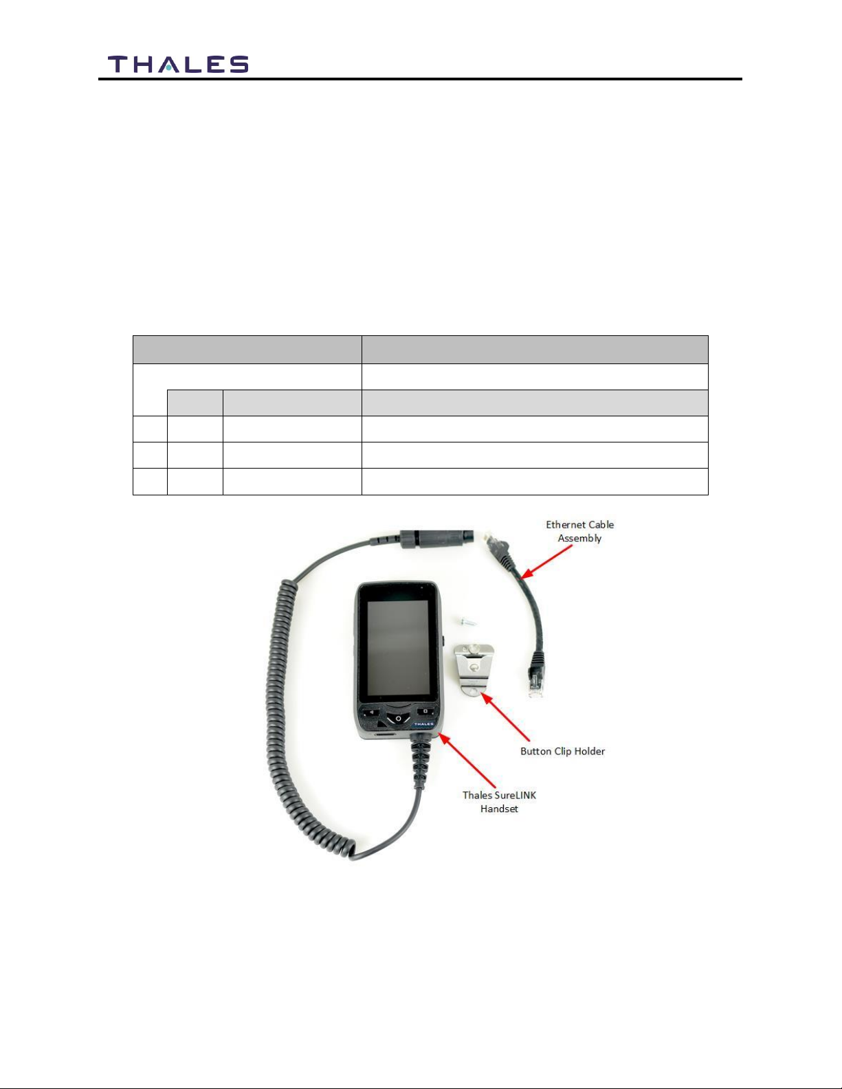
Kit Contents
The following list of equipment cones standard in the SureLINK kit and can be purchased
individually as spares, depending on your requirements and/or needs. (Refer to Figure 1-1.)
Table 1-1 Thales SureLINK Handset
Figure 1-1 Thales SureLINK Handset Kit Components
User Manual PN 84481 Rev 1
1-2
Page 9
Interface
Description
Touchscreen LCD
Ruggedized gorilla glass display used to select the LINK icon and
navigate through the screens.
Standard Phone
Microphone
Microphone port on bottom used during standard phone calls
Android Buttons
The three buttons perform the following functions:
Left button – back button returns to previous screen
Center button – Home Button - quick press returns to Home
screen or if display is off, turns on the display. Long press shuts
off display.
Right button – shows all active applications
THALES SURELINK HANDSET BASICS
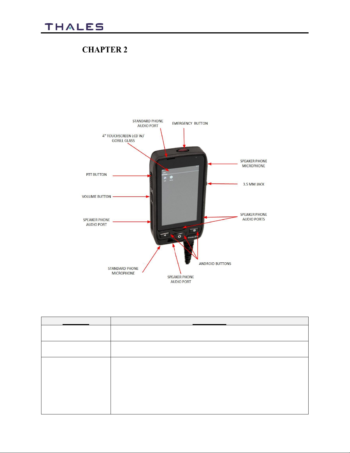
GETTING TO KNOW THE SURELINK
Thales SureLINK Interfaces
Figure 2-1 Thales SureLINK Interfaces
Table 2-1 Interface Description
User Manual PN 84481 Rev 1
2-1
Page 10
Interface
Description
Speaker Phone Audio
Ports
Multiple audio ports used to project voice in all directions during
speaker phone calls
3.5mm Jack
Allows a headset to be connected to the Handset. Standard headsets
and earbuds should work through the 3.5mm jack.
Speakerphone
Microphone
Microphone port on the side above the 3.5mm jack used during
speaker phone calls.
Note: Be careful not to cover up this microphone port while holding
the Handset during a speaker phone call.
Standard Phone Audio
Port
Audio port used for standard voice calls. Note that the audio port is
not in the center of the Handset, so for optimal sound, make sure the
port is correctly aligned with the ear.
Emergency Button
Dedicated button that when pressed and held enables an emergency
call or message to be made to a phone number or email address
PTT Button
Used to initiate PTT transmissions when PTT functionality becomes
available (Future).
Volume Button
This single button increases volume of the Handset when pressed and
held and decreases the volume of the Handset in steps when
sequentially pressed and then released quickly.
User Manual PN 84481 Rev 1
2-2
Page 11
NOTE
The following instructions assumes that the TU / BDU is
powered ON.
NOTE
The Handset has been preconfigured to operate on extension
1002, which corresponds to the second Iridium phone line.
INITIAL SET-UP
Installing the SureLINK Handset
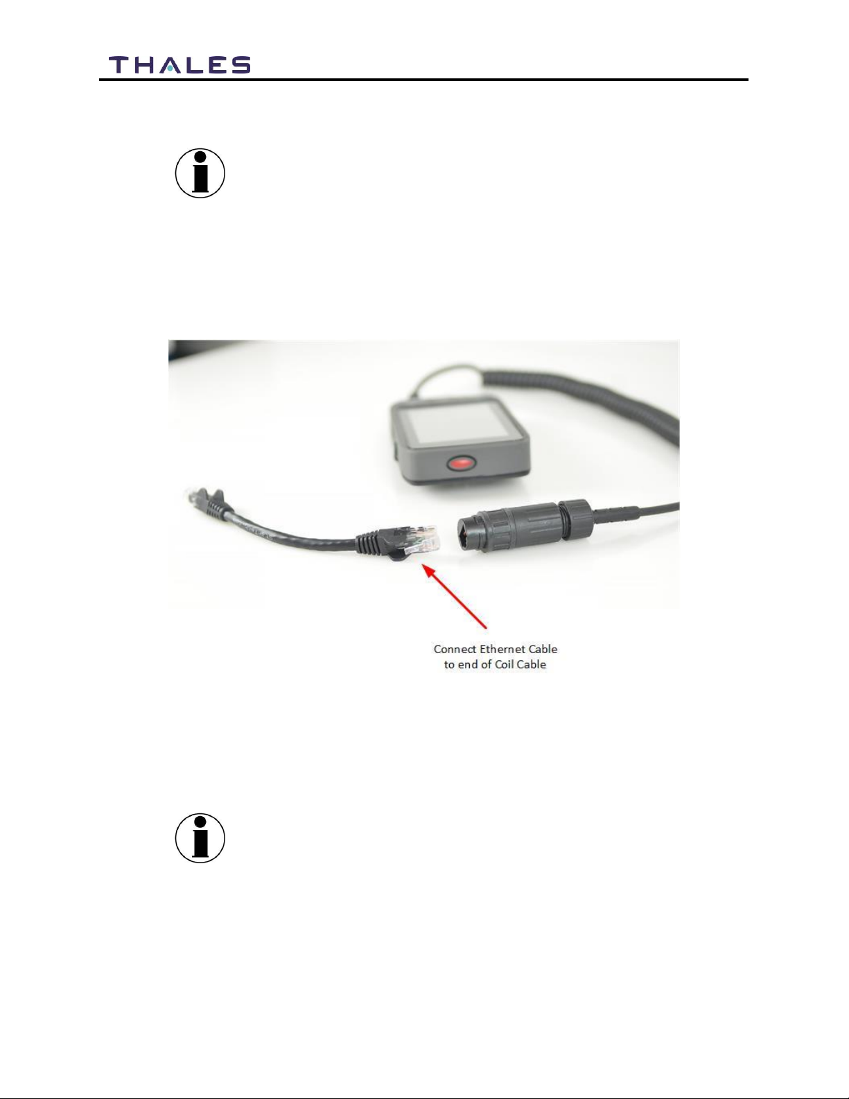
1. The installation of the SureLINK Handset is simply a matter of connecting the provided
Ethernet 6-inch male to male Ethernet connector between the female Ethernet connector
at the end of the coil cord and any one of the Ethernet/LAN connectors on the Terminal
(TU) / Below Deck Unit (BDU).
Figure 2-2 Ethernet Cable Connection to Handset
2. Once the SureLINK Handset is plugged in, the screen will power up. This may take a
minute or so. The Handset is now ready to use.
User Manual PN 84481 Rev 1
2-3
Page 12
NOTE
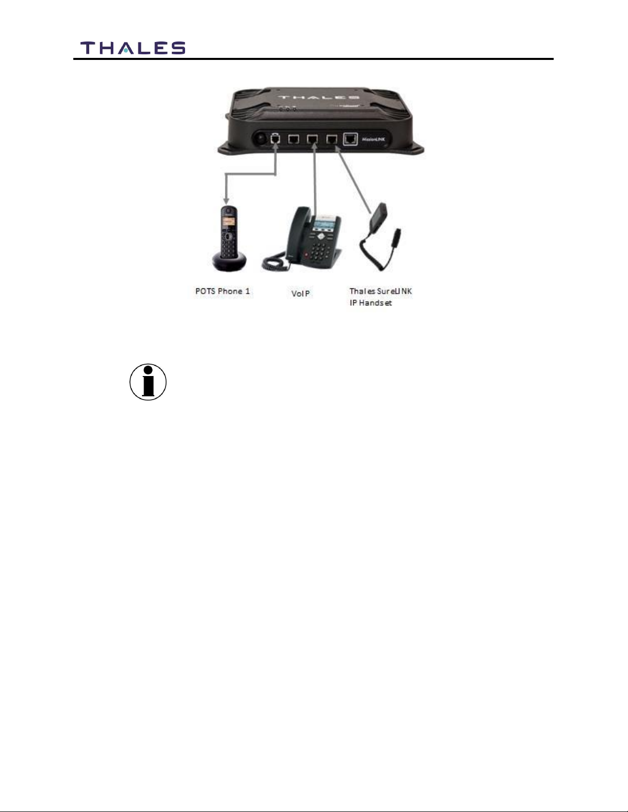
A longer Ethernet cable (not provided) can be substituted for the
6-inch provided cable to extend the SureLINK Handset farther
away from the TU / BDU. This cable must be compliant with the
Ethernet standard.
Figure 2-3 Thales SureLINK Handset Connected to TU /BDU
Mounting the SureLINK Handset
If mounting is desired, pre-drill and screw the mounting clip into a hard surface using the
provided two screws. The button on the backside of the SureLINK Handset will securely fit into
the clip for Handset storage while not in use.
Weather Proofing the Cord
The connection at the end of coil cord can also be more weather resistant by crimping a new
male Ethernet connector on the cable once it is pushed through the provided weather resistant
casing. This is not necessary and is left to the user to implement if desired.
User Manual PN 84481 Rev 1
2-4
Page 13
Getting Started (Plug And Play)
Once the Handset is plugged into the TU / BDU and has powered up, it is ready for operation.
(Note: the Handset does not have a ON/OFF BUTTON).
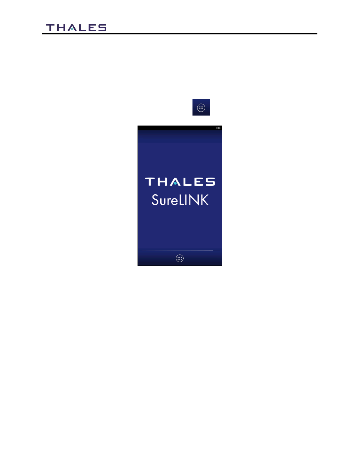
1. Press the center Android button to illuminate the screen. The Thales SureLINK home
screen will appear (or it may automatically open the LINK app and display the Dial Pad).
To open, select the icon at the bottom center ( ) of the Home Screen.
Figure 2-4 Thales SureLINK Home Screen
2. The next screen will be the Handset Application Display. From this screen, you will
select the LINK Application.
User Manual PN 84481 Rev 1
2-5
Page 14
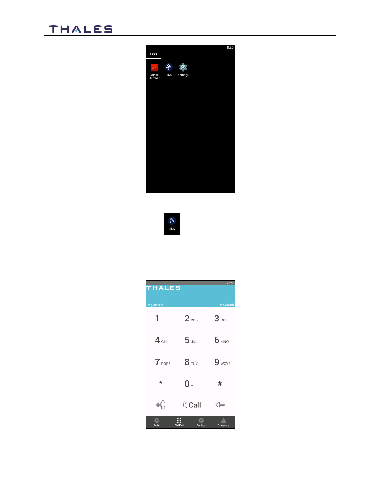
Figure 2-5 Thales Handset Application Screen
3. To open the LINK Application ( ), select the LINK icon.
4. When you first open the LINK Application (for the first time), the Dial Pad will be the
first screen that appears. To enter the Handset Portal, press the PORTAL icon at the
bottom left of the screen.
User Manual PN 84481 Rev 1
Figure 2-6 Thales Handset Dial Pad Screen
2-6
Page 15
NOTE
For information pertaining to the Management Portal on the
terminal unit, refer to either of the following user guides.
Thales MissionLINK® User Manual (Document # 84468)
Thales VesseLINK™ User Manual (Document # 84469)
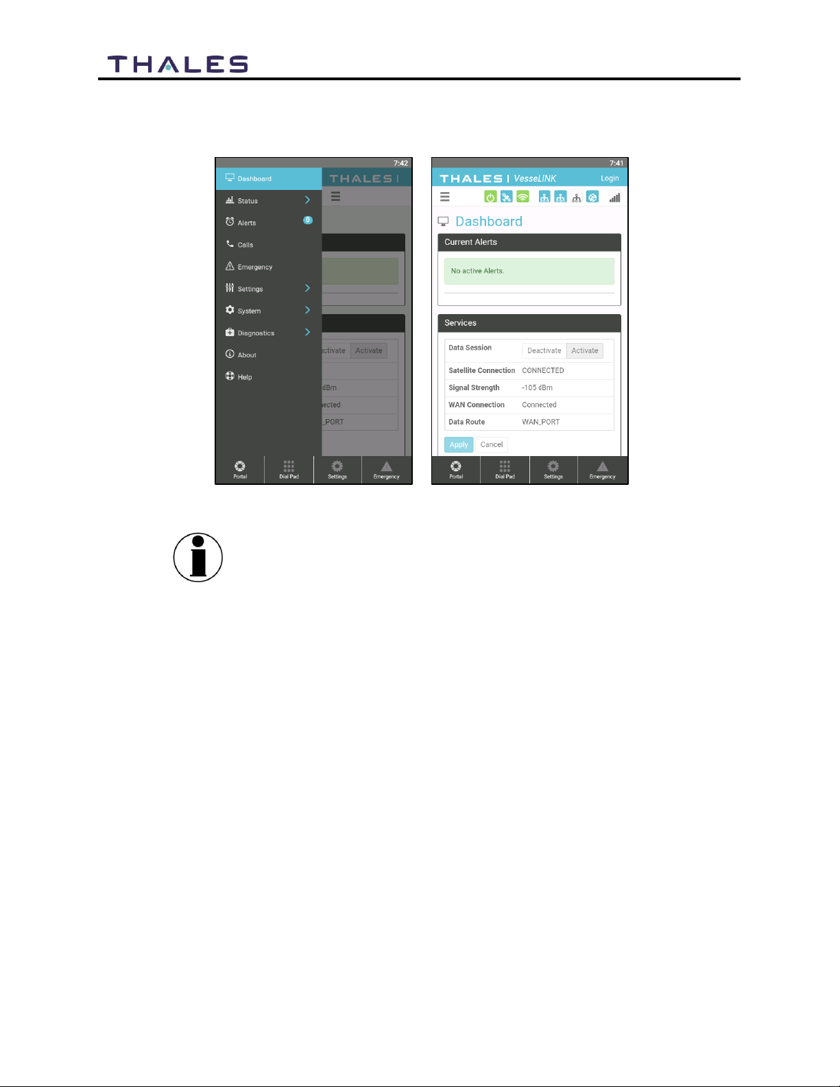
5. The LINK Application Dashboard will be displayed. The information contained in this
screen is the same as you will see the TU / BDU Management Portal.
Figure 2-7 Thales Link Portal
User Manual PN 84481 Rev 1
2-7
Page 16
Section
Parameters
Device
Display
When selected, the user can:
Adjust Brightness Level
Adaptive Brightness (enable / disable)
Set Sleep mode (15 secs, 30 sec, 1 minute, 2
minutes, 5 minutes, and 10 minutes)
Set Font size (Small, Normal, Large, and
Huge)
Sound Notification
When selected, the user can:
Set the volume level for Media
Set the volume level for Notification
Set the notification ringtone
Handset Properties
When selected, the user can:
Push-To-Talk (PTT) – Enable/Disable PTT
Emergency Call - Enable/Disable Emergency
Call Noise and Echo Cancellation – Enable /
Disable
Personal
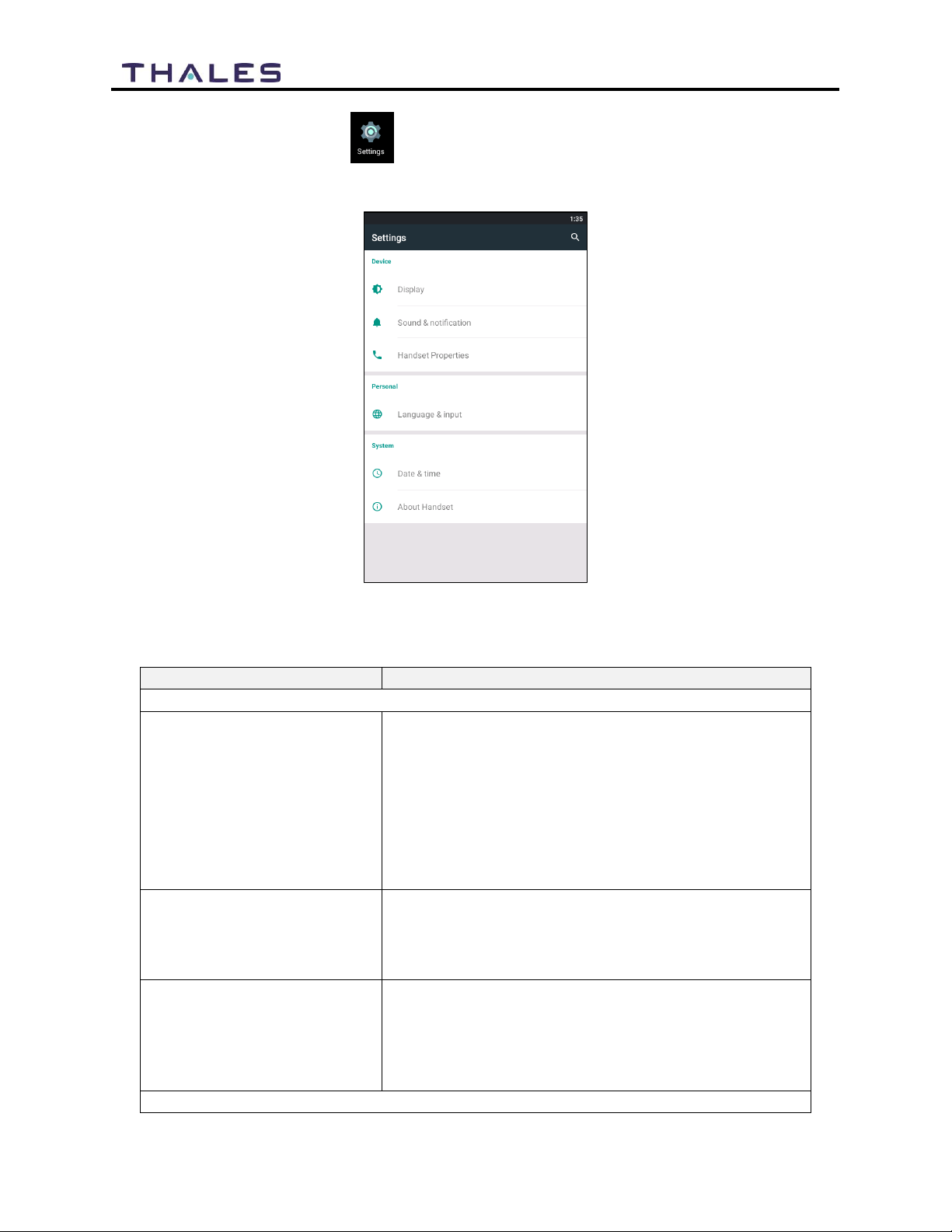
6. The SETTINGS ICON ( ) allows you to configure the handset. Refer to Figures 2-8
and 2-9.
Figure 2-8 Settings (Main Screen)
Table 2-2 Settings (Main Screen)
User Manual PN 84481 Rev 1
2-8
Page 17
Section
Parameters
Device
Language and Input
When selected, the user can:
Language – Set the desired language (English
is the default setting)
Keyboard and Input Methods – Keyboard type
and Android keyboard settings
System
Time and Date
When selected, the user can:
Automatically set date and time
Automatically set time zone
Select 24-hour format
Choose date format
About Handset
When selected, the following information is displayed:
System Updates
IP Address
MAC Address
Unit S/N
Model
Android Version
Kernel Version
Build Number
Reboot device
User Manual PN 84481 Rev 1
2-9
Page 18
NOTE
For information pertaining to the Management Portal on the
terminal unit, refer to either of the following user guides.
Thales MissionLINK® User Manual (Document # 84468)
Thales VesseLINK™ User Manual (Document # 84469)
ICON
Description
Portal Tab Button
Dial Pad Tab Button
Settings Tab Button
Emergency Tab Button
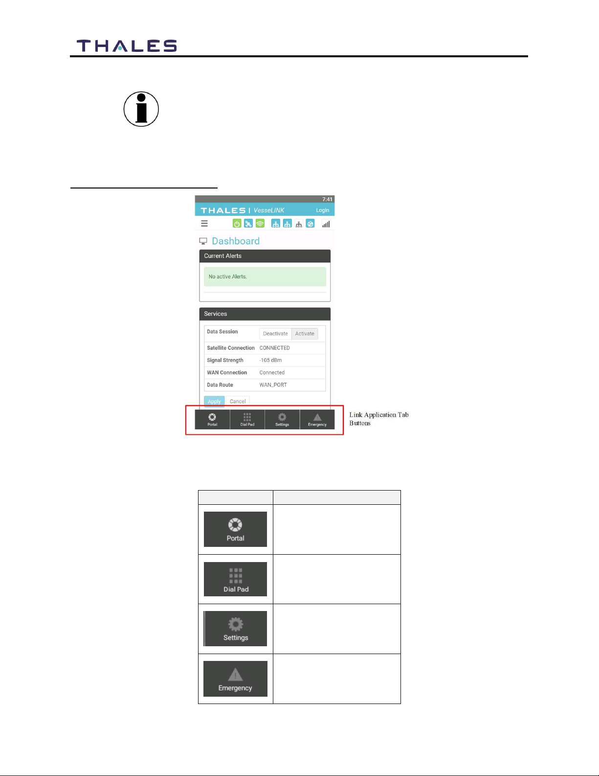
Link Application Menu Components
LINK Application Tab Buttons
Figure 2-9 LINK Applications Tab Buttons
Table 2-3 LINK Application Tab Buttons
User Manual PN 84481 Rev 1
2-10
Page 19

Portal Tab Button– When selected, the Management Portal will come up. Note, this has
the same menu components as you would see in the TU / BDU Management Portal.
(Refer to Figure 2-7)
Dial Tab Button – When selected, the phone key pad will be displayed. Telephone calls
are made from this screen. (Refer to Figure 3-1)
Settings Tab Button – Provides information relating accounts (existing and new) and
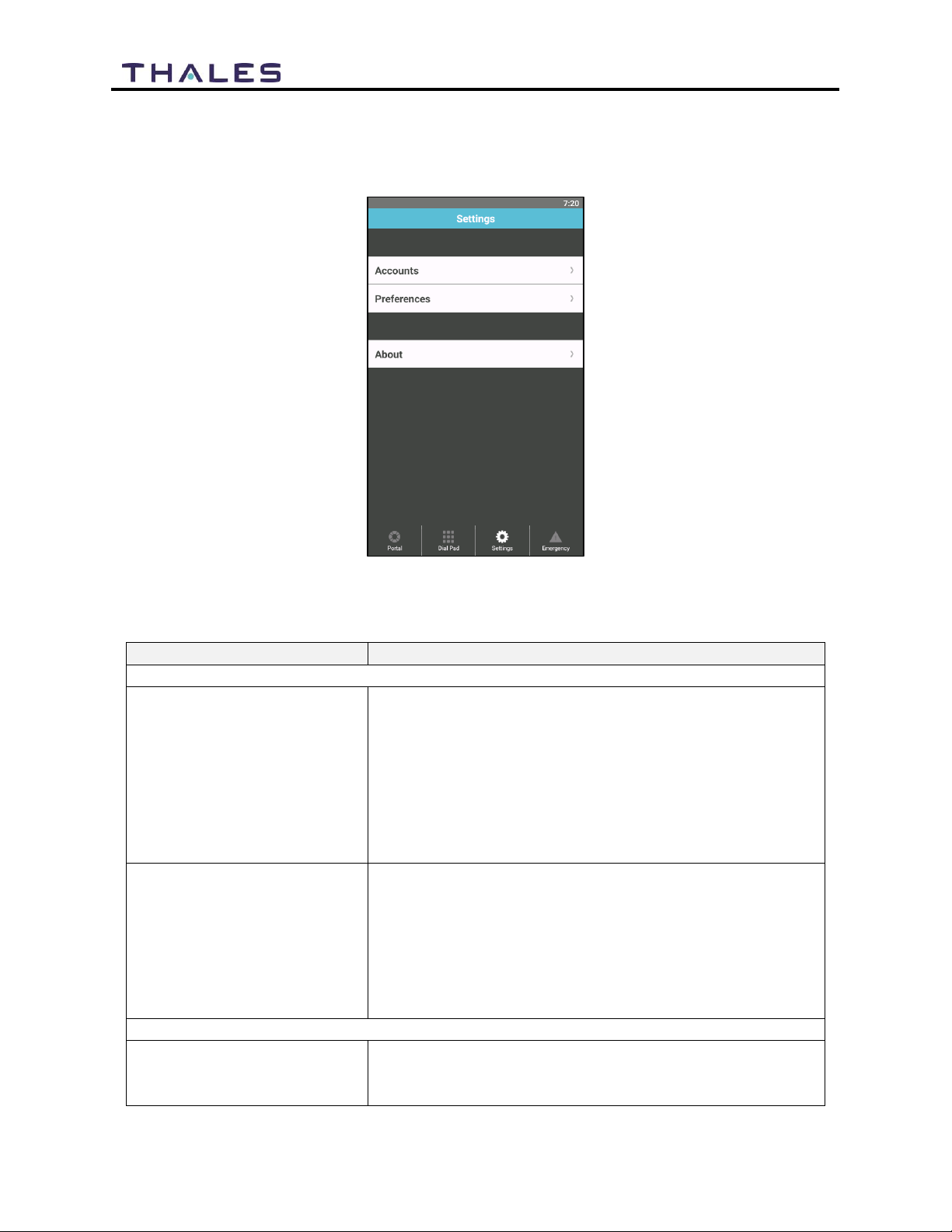
preferences (configure Management Portal name and password, setting up the Emergency
call number) (Refer to Figure 2-9)
Emergency Tab Button – Selecting this tab will open the Emergency Call screen. (Refer
to Figure 3-6)
User Manual PN 84481 Rev 1
2-11
Page 20
Section
Parameters
Accounts
Existing Account
Provides information relating to an existing account
already setup in the handset. Information includes:
General Information – Account label, enable the
use of mobile data, and enable/disable the account
User Details – Name of the device, username and
Domain (Default to sip.thaleslink)
Authentication – username and password.
New Account
Allows a new account to be established
General information – enter the new account name,
enable the use of mobile data, and enable/disable
the account
User details – enter the Display Name, Username,
and Domain
Authentication – enter the username and password
Preferences
Link Settings
Allows you to configure the Management Portal
Username and Password and to enable Emergency
Operation and configure the Emergency call number.
Link Application – Settings
From the Link Application, the SETTINGS Button allows you to:
Figure 2-10 LINK Application - Settings
Table 2-4 LINK Application Settings Buttons
User Manual PN 84481 Rev 1
2-1
Page 21

Section
Parameters
Audio Codecs
Provides information relating to Mobile Data Audio
Codecs and Wi-Fi Audio Codecs. (Information only)
About
About
Displays current version information
User Manual PN 84481 Rev 1
2-2
Page 22

OPERATION
SURELINK HANDSET OPERATION
The Thales SureLINK Handset operates on an Android operating system that has been
customized for the Handset operation. Many of the standard Android features and configuration
items have been removed, as they are not applicable to the Handset operation.
Points to remember:
If the default configuration of the terminal has changed, the Handset extensions must be
configured to match one of the Inbound Iridium Lines found in the Management Portal in
SETTINGS PHONE.
If the default configuration of the terminal has not changed, the Handset is set up to
operate on Extension 1002 using the Iridium phone number corresponding to that
extension.
The Android device IP address can be found by selecting the SETTINGS icon (not within
the LINK Application), then select ABOUT HANDSET
To reboot the handset, press and hold the MENU and BACK buttons simultaneously for
more than 6 seconds or simply unplug the handset from the terminal/BDU and plug it
back in.
Making a Call
To make a call over the satellite network,
1. Select the Dial Pad icon ( ), the Dial Pad screen will appear.
User Manual PN 84481 Rev 1
3-1
Page 23
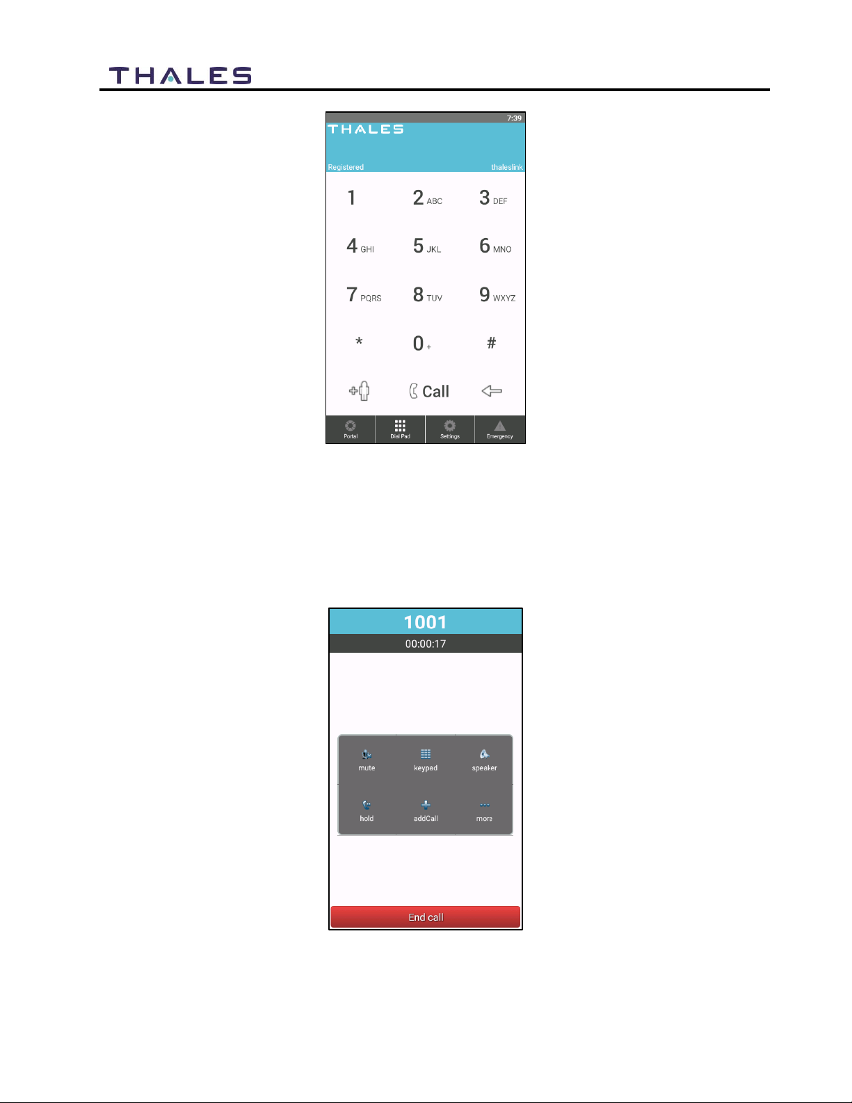
Figure 3-1 Thales Handset Dial Pad Screen
2. Dial 9 first and then the number to be called and press Call.
Once connected, if speakerphone mode is desired, follow instructions on the screen to
first enable the keypad and then select speaker. You can also bring up the keypad, mute
the Handset, put the call on hold or add a caller.
User Manual PN 84481 Rev 1
Figure 3-2 Handset Call Screen
3-2
Page 24
NOTE
To change the volume, press and hold the volume button to
increase volume and press and release sequentially to reduce the
volume.
NOTE
To make a local call using the PBX, dial the extension you want
to call (without the 9 first).
NOTE
To change the volume, press and hold the volume button to
increase volume and press and release sequentially to reduce the
volume.
Receiving a Call
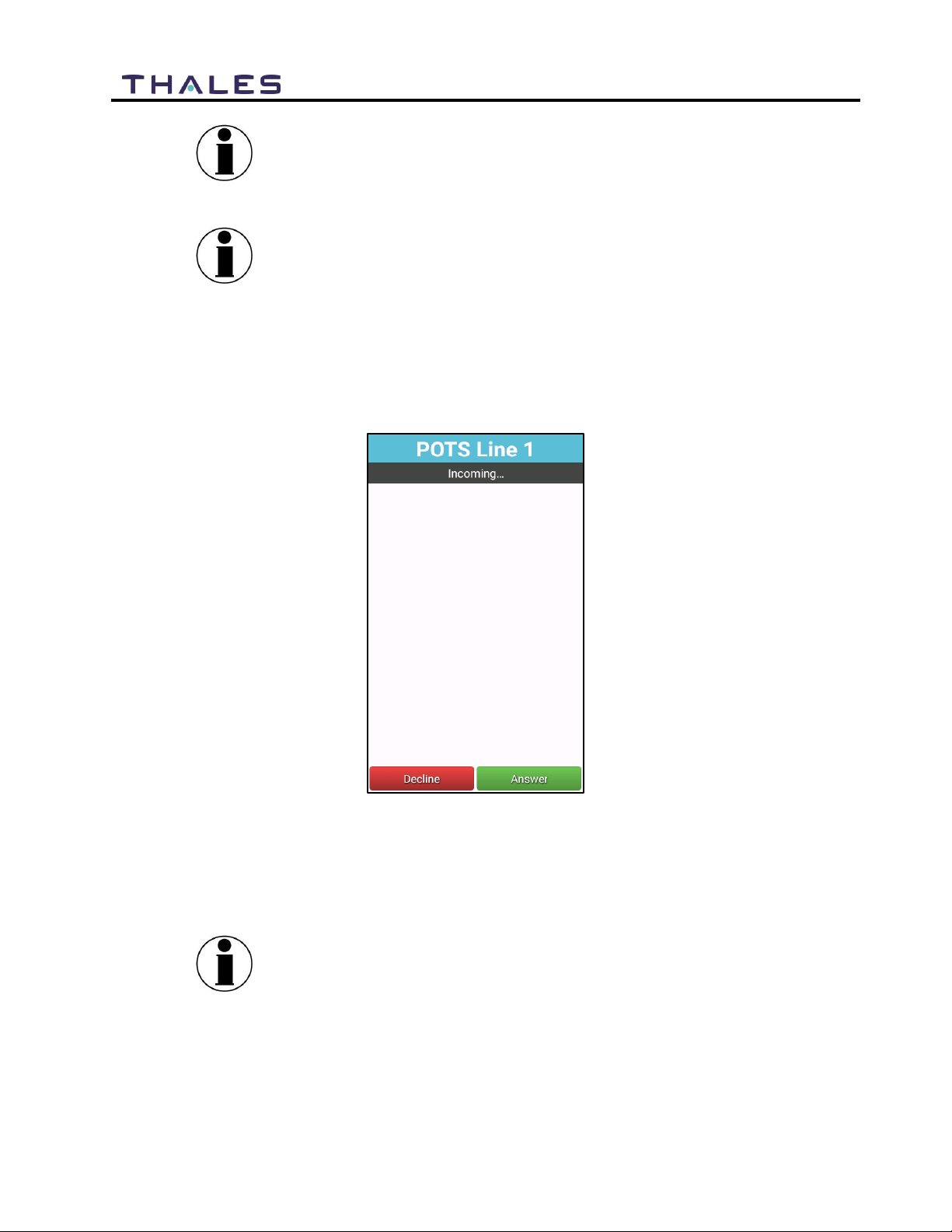
To receive a call from a caller over the satellite network, the caller would dial the Iridium
number that the Handset is mapped to. Select Answer when the Handset Rings.
Figure 3-3 Incoming Call Screen (Example)
Once connected, if speakerphone mode is desired, select the SPEAKER icon. You can
also bring up the keypad, mute the Handset, put the call on hold or add a caller. (Refer to
Figure 3-2)
User Manual PN 84481 Rev 1
3-3
Page 25
Making an Emergency Call
An Emergency Call can be made in two ways; either by selecting the Emergency Icon in the
LINK Application or by pressing and holding the Emergency Button at the top of the Handset.
Before either of these methods is used, the call number must first be configured. To do this:
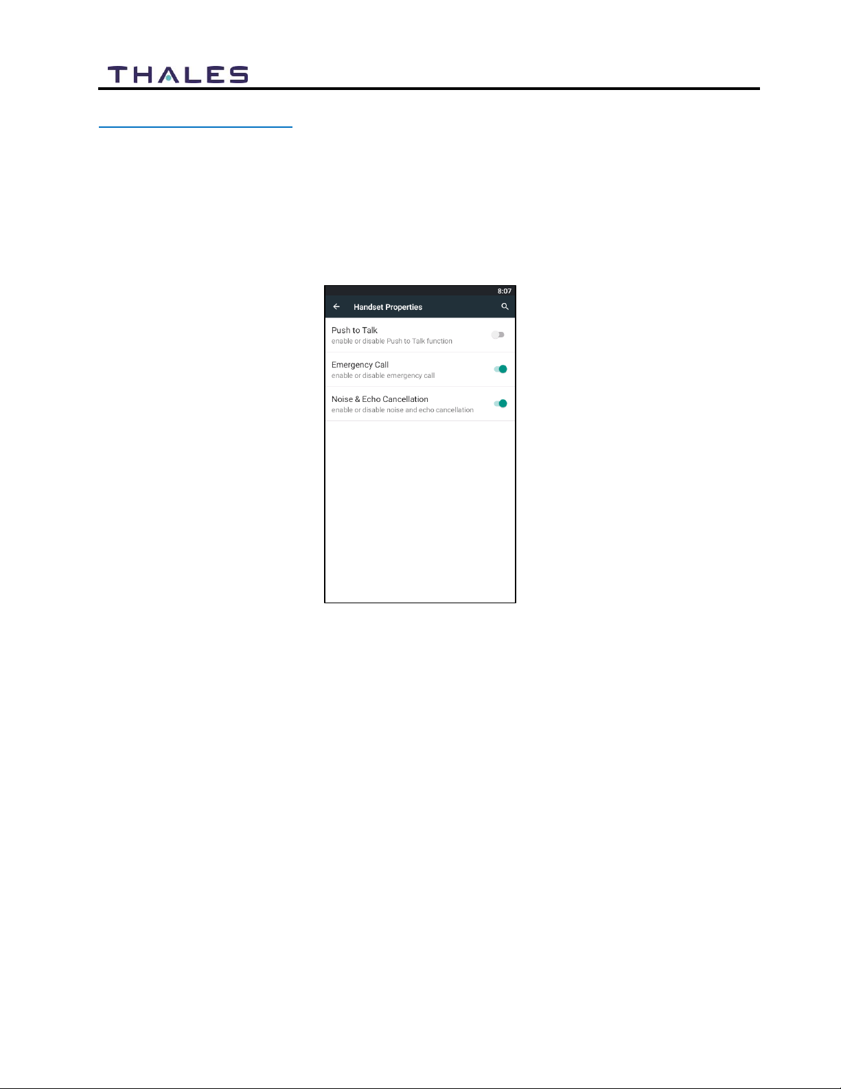
1. First select the SETTINGS icon (not within the LINK Application). Select HANDSET
PROPERTIES and select EMERGENCY CALL to enable. It will turn green when
enabled. It is gray when disabled.
Figure 3-4 Enable Emergency Call (Shown Enabled)
2. Within the LINK application, select the SETTINGS icon, then PREFERENCES, then
CONFIGURE.
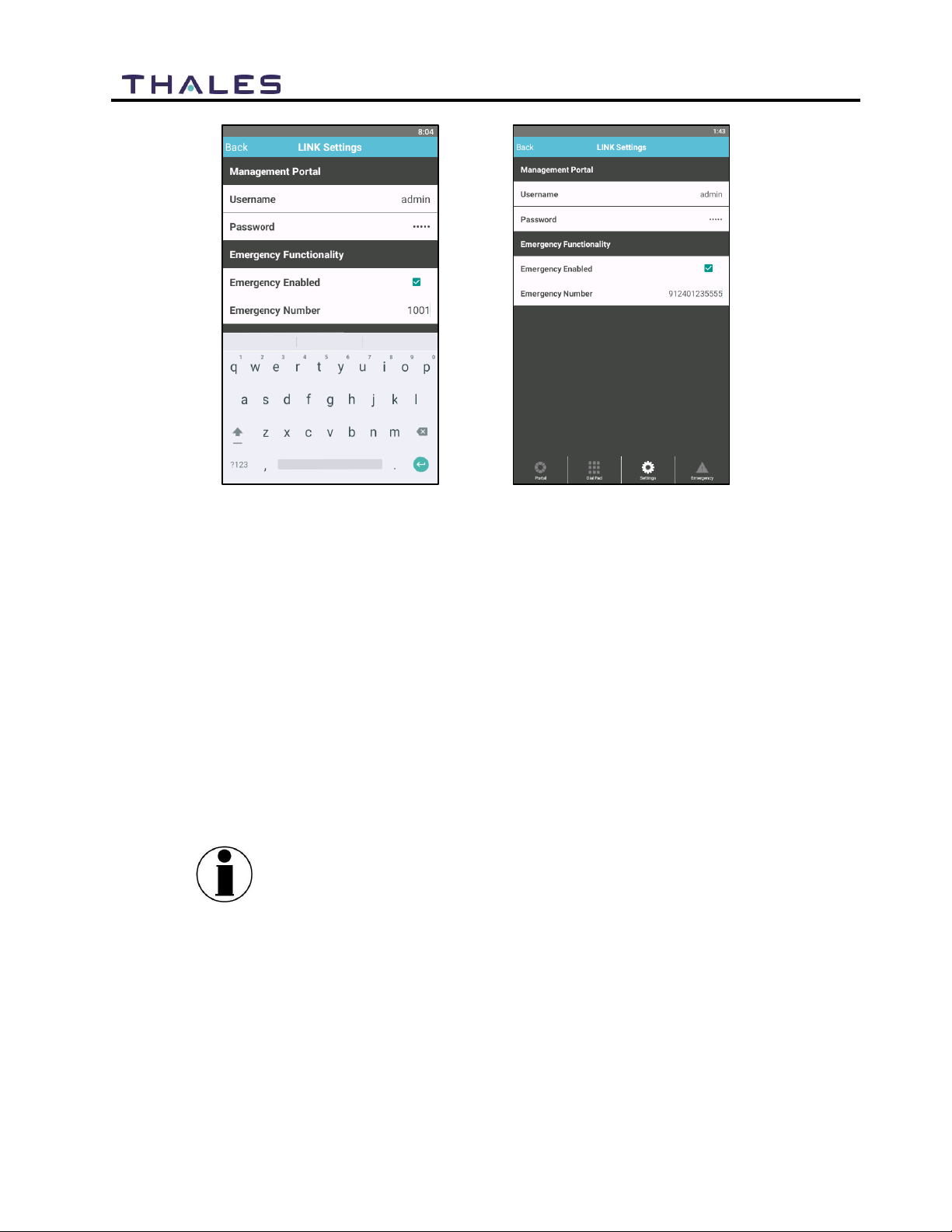
3. To configure the Emergency Number, select EMERGENCY NUMBER. A keypad will
be displayed. Enter the number (including 9) that you want to call when in an
Emergency. (Note – to remove the keypad, press the left Android button.)
User Manual PN 84481 Rev 1
3-4
Page 26
NOTE
If Emergency has not been enabled in the Settings and the
Emergency button is pressed and held, the Emergency screen
will appear and a message will appear asking if Emergency
should be enabled. If YES is selected, the Emergency sequence
will begin.
Figure 3-5 Enter the Emergency Number
4. Exit by pressing either the Left Android button or the HOME button.
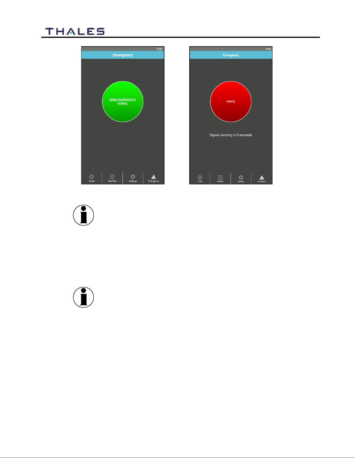
Method 1 – Press and Hold the red Distress button on the top of the Handset. The Emergency
Call sequence will initiate. A red CANCEL button appears on the screen with a 5-second
countdown. Press CANCEL if the call needs to be canceled. Emergency call will be initiated
after 5 seconds if not canceled.
Method 2 – Within the LINK application, select the EMERGENCY icon. Press the Green button
on the screen; SEND EMERGENCY SIGNAL. A red CANCEL button appears on the screen
with a 5-second countdown. Press CANCEL if the call needs to be canceled. Emergency call will
be initiated after 5 seconds if not canceled.
User Manual PN 84481 Rev 1
3-5
Page 27
NOTE
If no phone number has not been set up on the Handset but
Emergency is enabled, the Distress call uses the email address
that is set up in the Management Portal if one has been set-up. It
also sends out the current location coordinates.
NOTE
The user name and password must be correct in the LINK
Settings icon.
Figure 3-6 Emergency
MANAGEMENT PORTAL
The LINK application can be used to configure and monitor the MissionLINK and VesseLINK
systems through the Management Portal.
To access the Management portal within the LINK application, select the PORTAL icon. It may
take a minute to load. Make sure to Login to access Settings and other protected Admin data.
All Management Portal functionality is described in detail in the User Manual.
User Manual PN 84481 Rev 1
3-6
Page 28
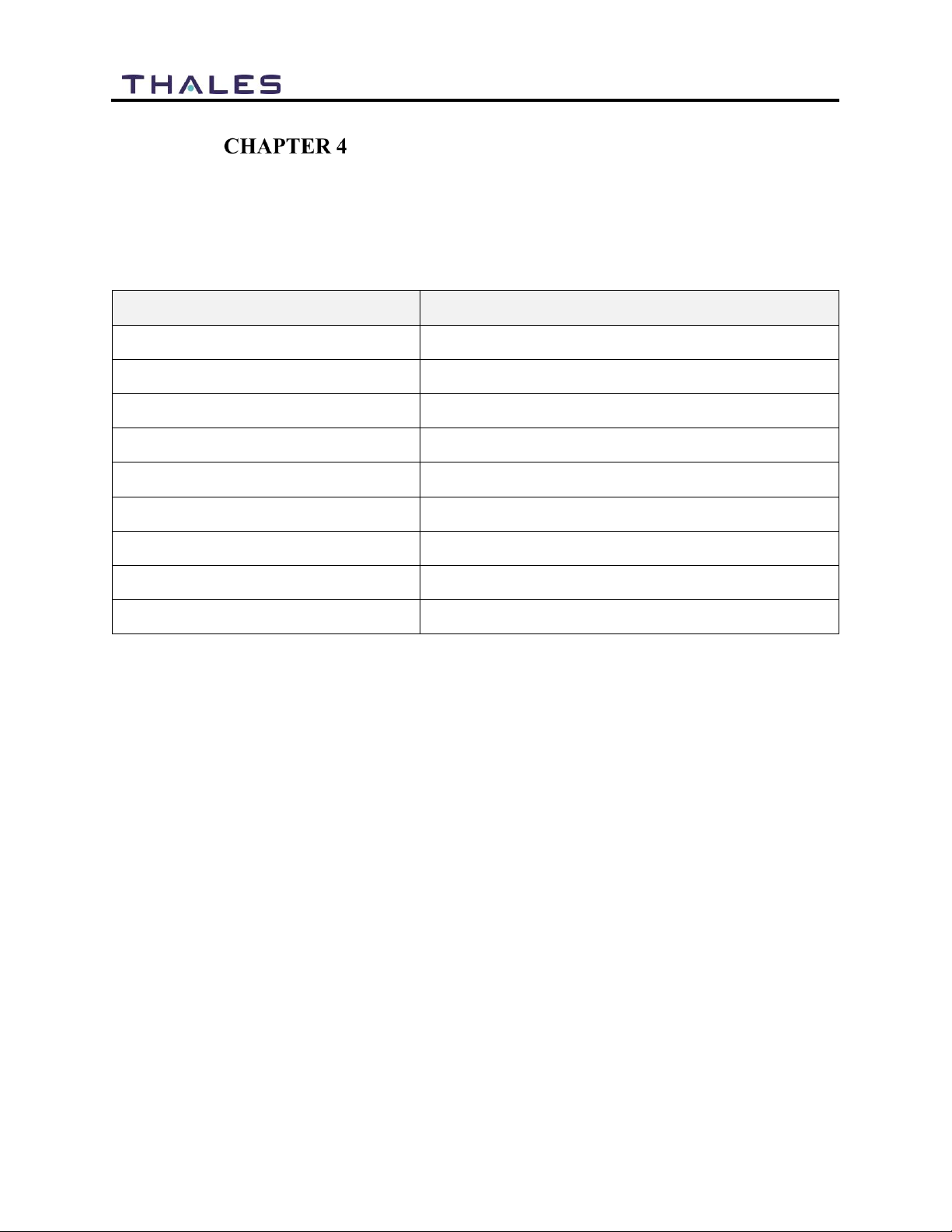
Category
Technical Specification
Operating Temperature
-20°C to +55°C
Regulatory
FCC Part 15 Class B, EN61000-4
Humidity
95% at 40°C
Audio Level (loud speaker)
>90 db SPL
Power Required
POE < 6.5 watts
Display
4” diagonal, 480 x 800 pixels
Vibration
MIL-STD-810G
Ingress Protection
IP65
Size/Weight
5”L x 3”W x 1”D, 10.5 oz
TECHNICAL SPECIFICATIONS
TECHNICAL SPECIFICATIONS
Table 4-1 Technical Specifications
User Manual PN 84481 Rev 1
4-1
Page 29

THIS PAGE INTENTIONALLY LEFT BLANK
User Manual PN 84481 Rev 1
4-2
Page 30

Acronym
Description
AC
Alternating Current
API
Application Programming Interface
BAA
Broadband Active Antenna
BAE
Broadband Application Electronics
BCX
Broadband Core Transceiver
BIT
Built In Test
DC
Direct Current
DHCP
Dynamic Host Configuration Protocol
DTMF
Dual Tone Multi-Frequency
EBB
Enhanced Broadband
ETSI
European Telecommunications Standards Institute
GPIO
General Purpose Inputs/Outputs
GPS
Global Positioning System
HGA
High Gain Antenna
HRLP
High Speed Radio Link Protocol
HTTP
Hypertext Transfer Protocol
ICMP
Internet Control Message Protocol
IP
Internet Protocol
ITU
International Telecommunications Union
LAN
Local Area Network
LED
Light Emitting Diode
LEO
Low Earth Orbiting
LGA
Low Gain Antenna
LOS
Line of Site
MO
Mobile Originated
msec
Milliseconds
MT
Mobile Terminated
NAS
Network Attached Storage
PBX
Private Branch Exchange
PCM
Pulse Code Modulation
PoE
Power Over Ethernet
POST
Power On Self-Test
POTS
Plain Old Telephone Service
PSTN
Public Switched Telephone Network
PTT
Push To Talk
QSG
Quick Start Guide
R/W
Read/Write
RF
Radio Frequency
ACRONYMS
ACRONYMS
Table 5-1 List of Acronyms
User Manual PN 84481 Rev 1
5-1
Page 31
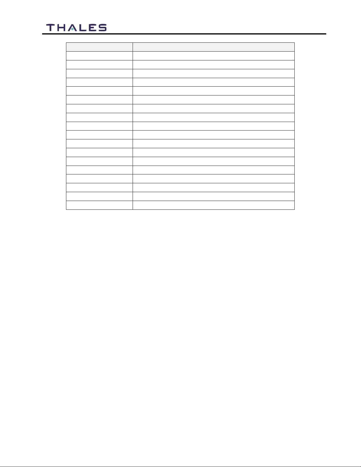
Acronym
Description
RGW
Radio Gate Way
SBC
Smart Battery Charger
SIM
Subscriber Identity Module
SIP
Session Initiation Protocol
SMBus
System Management Bus
SV
Satellite Vehicle
TCP
Transmission Control Protocol
TDSI
Thales Defense & Security, Inc.
TLS
Transport Layer Security
TU
Terminal Unit
UDP
User Datagram Protocol
UL/DL
Uplink/Downlink
VAD
Voice Activity Detection
VLAN
Virtual Local Area Network
VoIP
Voice of Internet Protocol
WAN
Wide Area Network
Wi-Fi
Wireless Network
WPA2-PSK
Wi-Fi Protected Access 2 – Pre-Shared Key
User Manual PN 84481 Rev 1
5-2
Page 32

Page 33

Thales Defense & Security, Inc.
22605 Gateway Center Drive | Clarksburg MD 20871
Toll-Free 1.800.324.6089 | Phone: 240.864.7000 | Fax: 240.864.7920
Email: [email protected] | Website:
www.thalesdsi.com
User Manual PN 84481 Rev 1
5-2
 Loading...