

Page 1
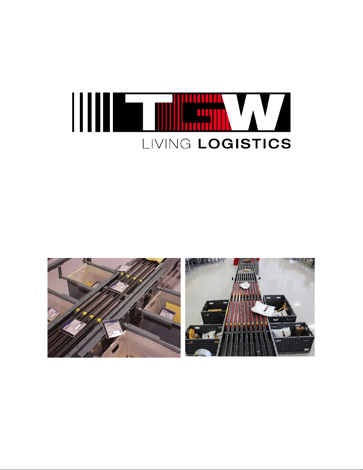
Installation, Operation, Maintenance
Manual
NBS®90 SP & NBS®90 PolySort
Narrow Belt Sorter (NBS)
P/N: 1193974
NBS90 SP (Small Parcels)
Revision Date: 4/25/2019
NBS90 PolySort
Page 2

NBS®90 PolySort & SP IOM
Table of Contents
CHAPTER 1: PURPOSE ...........................................................................................................................................4
CHAPTER 2: EQUIPMENT WARRANTY..................................................................................................................5
CHAPTER 3: WARNINGS & SAFETY INSTRUCTIONS ..........................................................................................6
3.1: TGW SYSTEMS RECOMMENDED STANDARDS FOR CONVEYORS ...........................................................................7
3.2: TGW RECOMMENDS PROPER LABELS FOR CONVEYOR TYPES .............................................................................8
3.3: WARNINGS AND SAFETY INSTRUCTIONS ..............................................................................................................9
3.4: TGW SYSTEMS CONVEYOR CONTROLS SAFETY GUIDELINES ............................................................................ 12
3.5: DEFINITION OF TERMS ..................................................................................................................................... 14
CHAPTER 4: NBS®90 POLYSORT APPLICATION GUIDELINES ....................................................................... 17
CHAPTER 5: NBS®90 SP (SMALL PARCELS) SELECTION GUIDELINES ....................................................... 20
CHAPTER 6: NBS RECEIVING & SITE PREPARATION ...................................................................................... 22
6.1: NBS PARTS INVENTORY & IDENTIFICATION ....................................................................................................... 23
CHAPTER 7: NBS PARTS INVENTORY & IDENTIFICATION.............................................................................. 24
CHAPTER 8: NBS INSTALLATION DETAILS ...................................................................................................... 25
8.1: NBS GENERAL ELECTRICAL REQUIREMENTS .................................................................................................... 26
8.2: NBS90 POLYSORT TGW-ERMANCO CONTROLS GUIDELINES ........................................................................ 28
8.3: NBS90 SP ELECTRICAL CONTROL ENCLOSURE ............................................................................................... 37
8.4: NBS GEAR MOTOR ACTIVATION ...................................................................................................................... 38
8.5: NBS ELEVATIONS ........................................................................................................................................... 40
8.6: NBS SUPPORTING ARRANGEMENT .................................................................................................................. 40
8.7: NBS SUPPORTS & CONNECTIONS ................................................................................................................... 41
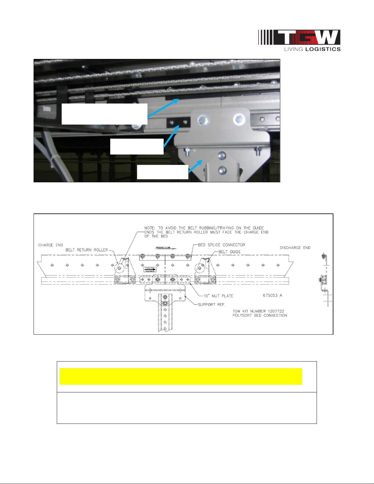
8.8: NBS90 POLYSORT BED CONNECTION KIT ......................................................................................................... 42
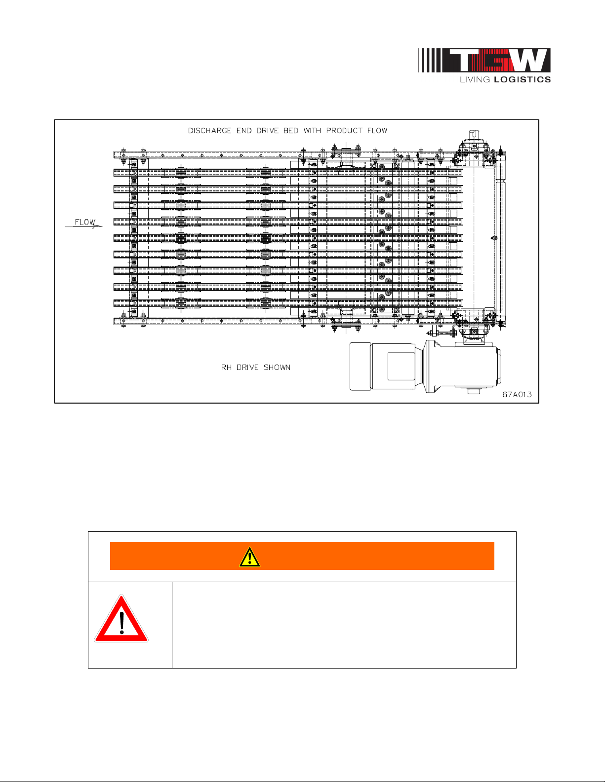
8.9: NBS90 POLYSORT COMPONENT ORIENTATION ................................................................................................ 43
8.10: NBS90 POLYSORT TRANSFER GENERAL LAYOUT .......................................................................................... 44
8.11: NBS90 POLYSORT SENSING SWITCHES ........................................................................................................ 45
8.12: NBS90 SP SORTER TRANSFER GENERAL LAYOUT ......................................................................................... 46
8.13: NBS90 POLYSORT CEILING SUPPORTED ....................................................................................................... 47
8.14: NBS ALUMINUM EXTRUSION T-NUT CONNECTORS ......................................................................................... 49
8.15: NBS BELT INSTALLATION .............................................................................................................................. 50
8.16: NBS BELT SPECIFICATIONS AND LACING ........................................................................................................ 52
CHAPTER 9: NBS PNEUMATIC GENERAL GUIDELINES .................................................................................. 53
9.1: NBS90 POLYSORT PNEUMATIC ....................................................................................................................... 54
9.2: NBS90 POLYSORT AIR SUPPLY REQUIREMENTS.............................................................................................. 55
9.3: NBS90 SP AIR SUPPLY REQUIREMENTS ......................................................................................................... 56
9.4: NBS90 SP & POLYSORT AIR LINE CONNECTIONS ............................................................................................ 57
9.5: NBS90 SP SOLENOIDS ................................................................................................................................... 58
9.6: NBS AIR REGULATOR LOCK OUT VALVE ON AND OFF POSITION ....................................................................... 59
9.7: NBS COMMISSIONING OF EQUIPMENT .............................................................................................................. 60
CHAPTER 10: NBS MAINTENANCE & TROUBLESHOOTING ........................................................................... 62
10.1: NBS MAINTENANCE CHECKLIST..................................................................................................................... 65
10.2: MAINTENANCE SCHEDULE ............................................................................................................................. 66
10.3: NBS TROUBLESHOOTING GUIDE ................................................................................................................... 68
10.4: NBS REPAIR PROCEDURES ........................................................................................................................... 70
CHAPTER 11: PARTS IDENTIFICATION .............................................................................................................. 71
11.1: REPLACEMENT PARTS IDENTIFICATION ........................................................................................................... 71
P/N: 1193974 Revision Date: 4/25/2019 Page 2 of 83
Page 3

NBS®90 PolySort & SP IOM
11.2: SPARE PARTS PRIORITY LEVEL EXPLANATIONS .............................................................................................. 71
11.3: NBS90 POLYSORT INTERMEDIATE BED AR W/AIR TAKE-UP 4’0” .................................................................... 72
11.4: NBS90 POLYSORT BELT TAKE-UP ................................................................................................................ 74
11.5: NBS90 POLYSORT END PULLEY AR 4’0” W/AIR TAKE-UP .............................................................................. 75
11.6: NBS90 POLYSORT END PULLEY AR 1’6” ....................................................................................................... 77
11.7: NBS90 POLYSORT TRANSFER ASSEMBLY ..................................................................................................... 78
11.8: NBS90 SP & POLYSORT ENCODER ASSEMBLY ............................................................................................. 79
11.9: NBS90 SP TRANSFER ASSEMBLY REPLACEMENT PARTS DIAGRAM ................................................................ 80
11.10: NBS90 SP END PULLEY ASSEMBLY REPLACEMENT PARTS DIAGRAM ........................................... 81
WORKS CITED ....................................................................................................................................................... 82
TGW GENERAL INFORMATION ................................................................................................................................ 82
TGW SYSTEMS INFORMATION ............................................................................................................................ 83
P/N: 1193974 Revision Date: 4/25/2019 Page 3 of 83
Page 4
NBS®90 PolySort & SP IOM
WARNING
Chapter 1: PURPOSE
IOM Purpose
It is the intent of TGW Systems, through this
manual, to provide information that acts as a
guide in the installation, operation, and
maintenance of TGW Systems supports and
connections.
This manual describes basic installation
practices, assembly arrangements, preventive
maintenance, and assists in replacement parts
identification.
This service manual is intended for use by
personnel who are knowledgeable of installation
and safe working practices on conveyor systems.
Not all applications and conditions can be
covered; therefore, this manual is to be used
ONLY as a guide.
If additional copies of this manual are needed or
if you have any question concerning the
conveyor please contact your TGW Distributor or
TGW Lifetime Services at 231-798-4547 or visit
TGW at https://www.tgw-conveyor.com/
for
maintenance videos and other application
information.
Manual Structure
You should receive a separate
documentation for each product line of TGW
Systems implemented in your installation. You
can identify the respective product line on the
back of the folder or on the cover sheet of the
IOM (Installation Operation Maintenance Manual)
• Pay attention to the safety
instructions!
• Prior to working at or in the
immediate vicinity of the system it is
recommended that you make
yourself familiar with the safety
instructions included in the present
document!
P/N: 1193974 Revision Date: 4/25/2019 Page 4 of 83
Page 5

NBS®90 PolySort & SP IOM
Chapter 2: EQUIPMENT WARRANTY
TGW Systems Equipment Warranty
TGW Systems warrants that the material and workmanship
entering into its equipment is merchantable and will be
furnished in accordance with the specifications stated.
TGW Systems agrees to furnish the purchaser without
charge any part proved defective within 2 years from date of
shipment provided the purchaser gives TGW Systems
immediate notice in writing and examination proves the
claim that such materials or parts were defective when
furnished. For drive components specific to XenoROL
Xeno belts, slave Xeno belts, drive spools, standard and
speed-up, and spacers), this warranty shall be extended to
five years of running use, provided the conveyors are
applied, installed and maintained in accordance with TGW
Systems published standards. Other than the above, there
are no warranties which extend beyond the description on
the face hereof. Consequential damages of any sort are
wholly excluded.
The liability of TGW Systems will be limited to the
replacement cost of any defective part. All freight and
installation costs relative to any warranted part will be at the
expense of the purchaser. Any liability of TGW Systems
under the warranties specified above is conditioned upon
the equipment being installed, handled, operated, and
maintained in accordance with the written instructions
provided or approved in writing by TGW Systems.
®
(i.e.
TGW Environment Standards
TGW equipment is designed to be installed in a clean,
dry warehouse environment. Exposure to extreme
humidly, direct sunlight, blowing dirt or rain can
permanently damage some components of TGW
conveyor. In particular, the curing agents in concrete
are known to attack and degrade the urethane
conveyor components.
When installing conveyor on a new construction site,
be sure that the concrete is properly cured before
setting conveyor on it. In addition, if conveyors are
stored in the proximity of curing concrete, proper
ventilation must be used to direct the curing agent
fumes away from the conveyor.
Failure to comply with these guidelines will void the
TGW warranty on any failed components that result
from these environment issues.
The warranties specified above do not cover, and TGW
Systems makes no warranties which extend to, damage to
the equipment due to deterioration or wear occasioned by
chemicals, abrasion, corrosion or erosion; Purchaser's
misapplication, abuse, alteration, operation or maintenance;
abnormal conditions of temperature or dirt; or operation of
the equipment above rated capacities or in an otherwise
improper manner.
THERE ARE NO WARRANTIES, EXPRESSED OR
IMPLIED, INCLUDING, BUT NOT LIMITED TO,
WARRANTIES OF MERCHANTABILITY OR FITNESS FOR
A PARTICULAR PURPOSE, EXTENDING BEYOND
THOSE SET FORTH IN THIS STATEMENT OF
WARRA NT Y.
Rev 9/23/2016
P/N: 1193974 Revision Date: 4/25/2019 Page 5 of 83
Page 6
NBS®90 PolySort & SP IOM
WARNING
Chapter 3: WARNINGS & SAFETY INSTRUCTIONS
TGW Safety Recommendation
For additional safety information:
TGW agrees to the following safety instruction or
guidelines listed within this manual. This is not to
conflict with your state or legal requirements.
TGW Recommends for maintenance or repair
purposes, to incorporate a lock out or tag procedure.
To ensure all starting devices, prime movers, or
powered accessories are off before attempting to
maintenance or repair.
The procedures below are designed to protect
everyone involved with the conveyor against an
unexpected restart. To include understanding of
potential hazard of stored energy, which can exist
after the power source is locked out.
For additional information, refer to the latest issue of
ANSI Z244.1, American National Standard for
Personnel Protection − Lockout/Tagout of Energy
Sources− Minimum Safety Requirements.
http://www.ansi.org/
OSHA 29CRF Part 1910.147 “Control of Hazardous
Energy Sources (Lockout/Tagout)”, which includes
requirements for release of stored energy and OSHA
Safety and Health Regulations for Construction
1926.555 Conveyors
https://www.osha.gov/
Conveyor Design and Safety Guidelines
A safety risk evaluation is required for all of our
standard equipment. The safety risk evaluation
considers every potential hazard on the conveyor,
weighs the probability and the severity of the potential
injury, and addresses methods of mitigation to make
the risk of injury either low or negligible. We use the
ANSI B11 TR3 standards for all of our risk evaluation.
In addition, all of our equipment is designed to comply
with the following national and industry standards:
• ANSI Z535.1 – Safety Color Code
• ANSI Z244.1 – Lockout/Tagout of Energy Sources
• ASME B15.1 – Safety standard for Mechanical Power
Transmission Apparatus
• ASME B20.1 – Safety standard for Conveyors and
Related Equipment
• CEMA – Safety Standards and Labels
• OSHA 1910.147 – The Control of Hazardous Energy
• OSHA 1910.212 - General Requirements for all
Machines
• OSHA 1910.95 – Occupational Noise Exposure
D
efinitions:
• ANSI = American National Standard Institute
• ASME = American Society of Mechanical Engineers
• CEMA = Conveyor Equipment Manufacturers
Association
• OSHA = Occupational Safety and Health
A
dministration
• Safety: Always lock out power source and follow recommended safety procedures.
P/N: 1193974 Revision Date: 4/25/2019 Page 6 of 83
Page 7
NBS®90 PolySort & SP IOM
3.1: TGW SYSTEMS RECOMMENDED STANDARDS FOR CONVEYORS
ANSI Standards for Conveyors
It is essential for safe and efficient system operation that safety
information and guidelines presented here are properly understood
and implemented.
TGW recognizes American National Standard Institute (ANSI)
booklet entitled Safety Standards for Conveyors and Related
Equipment B20.1. For more information go to:
http://webstore.ansi.org/default.aspx
With any piece of industrial equipment, conditions exist that might
cause injury to you or your co-workers. Because it is not possible to
describe each potentially hazardous situation that might develop,
you must be alert at all times for unsafe conditions. To avoid injury,
use maximum possible care and common sense and adhere to all
safety standards. Take special care while maintaining and
inspecting electrical equipment and devices. All personnel working
on or around the system should be aware of, and adhere to, all
CAUTION, DANGER, and WARNING signs.
Labels or signs are posted to reduce the risk of injury to all
personnel. Never assume that the signs and notices are applicable
only to inexperienced personnel. Maintain signs in a legible
condition. Contact your supervisor to post additional safety signs if
you feel they are necessary. http://www.ansi.org/
ANSI Conveyor Safety Rules
• Conveyor safety
rules, as well as specific regulations and guidelines listed
in this publication:
• DO NOT touch moving Conveyor parts.
• DO NOT walk, ride, or climb on the Conveyor.
• DO NOT operate the
other protective guards removed.
Conveyor
with chain guards or
• Keep jewelry, clothing, hair, etc., away from the
Conveyor.
• Know the location and function of all start/stop devices
and keep those devices free from obstruction.
• Clear all personnel from the equipment before starting
the Conveyor.
• DO NOT attempt to clear product jams while the
Conveyor is running.
• Allow only trained and authorized personnel to maintain
or repair Conveyor equipment.
• DO NOT load the Conveyor beyond specified design
limits.
• DO NOT attempt to make repairs to the Conveyor while it
is running.
• DO NOT modify equipment without checking with the
manufacturer.
• DO NOT operate or perform maintenance on equipment
when taking any type of drug, sedative, when under the
influence of alcohol, or when over fatigued.
• Report any unsafe condition to your supervisor or
maintenance staff.
CEMA Standards for Conveyors
The Conveyor Equipment Manufacturers Association (CEMA)
provides safety information related to conveyor systems. There are
Conveyor Safety Video and Conveyor Safety Poster produced by
CEMA.
TGW recommends these videos for training and education
purposes as part of a safe working environment around conveyor
equipment. The videos introduce awareness of operations,
personnel, maintenance technicians, and management to safety
hazards commonly associated with the automated material handling
conveyor equipment.
The safety posters reviews important safety labels and are intended
to be posted in public places as a day-to-day reinforcement of good
safety practices. These posters can be downloaded from the CEMA
Website at http://www.cemanet.org/safety-label-posters
information for both the safety poster and the videos can be
purchased from CEMA. Visit their website –
For additional information or contact
them at:
CONVEYOR EQUIPMENT
MANUFACTURERS ASSOCIATION
5672 Strand Ct., Suite 2
Naples, Florida 34110
239.514.3441
CEMA Safety Label Meanings
ANSI Z535.4 – Product Safety Signs and Labels
The word or words that designate a degree or level of hazard
seriousness. The signal words for product safety signa
are: DANGER, WARNING, and CAUTION.
DANGER -Indicates an imminently hazardous situation which, if not
avoided, will result in death or serious injury. This signal word is to
be limited to the most extreme situations.
WARNING – Indicates potentially hazardous situation which, if not
avoided, could result in minor or moderate injury. It may also be
used to alert against unsafe practices.
CAUTION – Indicates a potentially hazardous situation which, if not
avoided, may result in minor or moderate injury. It may also be used
to alert against unsafe practices.
http://www.cemanet.org/cema-safety-label-meanings/
www.cemanet.org
or for more
P/N: 1193974 Revision Date: 4/25/2019 Page 7 of 83
Page 8
NBS®90 PolySort & SP IOM
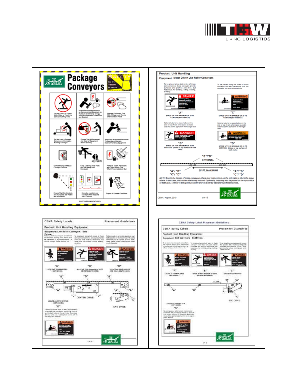
3.2: TGW RECOMMENDS PROPER LABELS FOR CONVEYOR TYPES
Shown below are some samples of labels applicable to conveyor standards.
P/N: 1193974 Revision Date: 4/25/2019 Page 8 of 83
Page 9
NBS®90 PolySort & SP IOM
WARNING
CAUTION
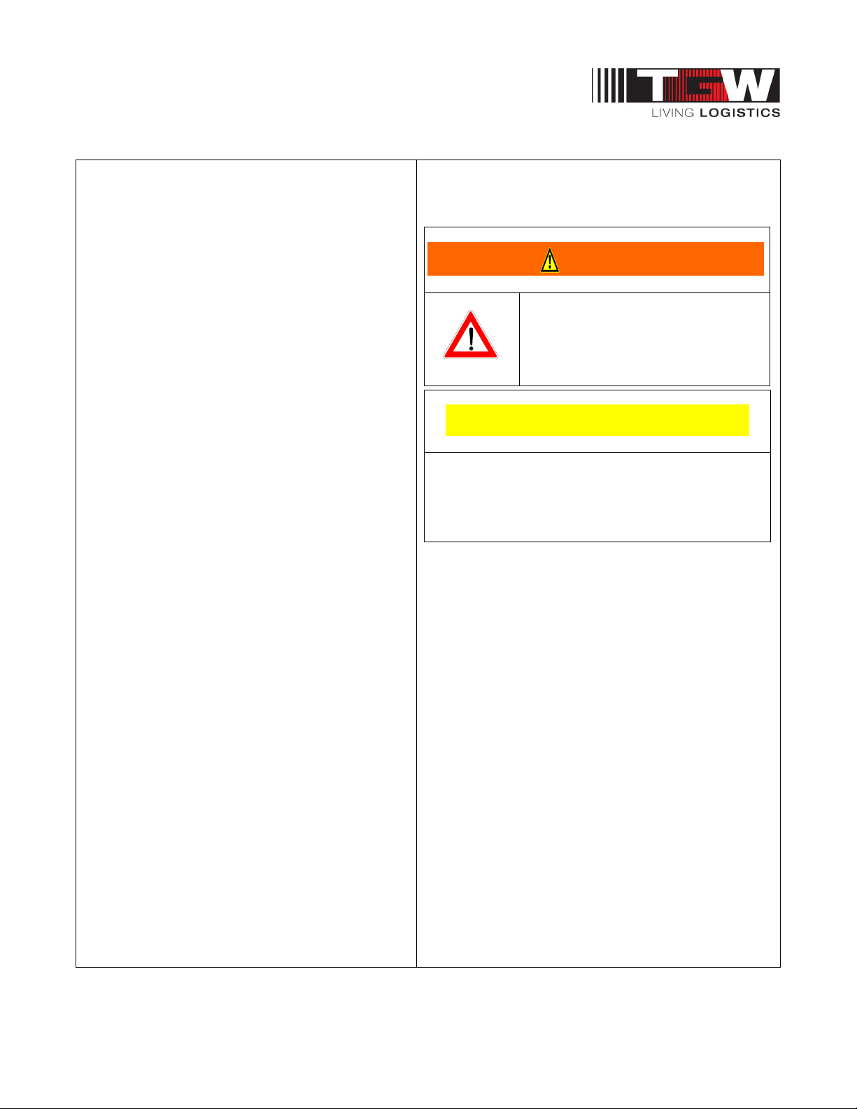
3.3: WARNINGS AND SAFETY INSTRUCTIONS
Failure to follow the instructions and cautions
throughout this manual and warning label on
the conveyor may result in injury to personnel
or damage to the equipment.
Your TGW Systems conveyor is powered by a
motor and can be stopped only by turning off
electrical power to the motor. As with all
powered machinery, the drive-related
components – including sprockets, chains,
shafts, universal joints, and pneumatic devices
– can be dangerous. We have installed or
provided guards to prevent accidental contact
with these parts, along with warning labels to
identify the hazards.
Special attention must be paid to the following
areas of this manual:
• Indicates a potentially hazardous
situation, which, if not avoided,
• Indicates a situation, which, if not avoided, could
result in property damage.
could result in death or serious
injury.
P/N: 1193974 Revision Date: 4/25/2019 Page 9 of 83
Page 10
NBS®90 PolySort & SP IOM
WARNING
3.3.1: Warnings and Safety Instructions
• After maintenance, REPLACE guards immediately.
• Keep ALL warning labels clean and clear of any obstructions.
• Never remove, deface, or paint over WARNING or CAUTION labels. Any damaged label
will be replaced by TGW Systems at no cost by contacting Lifetime Services.
• It is very important to instruct personnel in proper conveyor use including the location
and function of all controls.
• Special emphasis must be given to emergency stop procedures.
• It is important to establish work procedures and access areas, which do not require any
part of a person to be under the conveyor.
• It should be required that long hair is covered by caps or hairnets.
• Loose clothing, long hair, and jewelry must be kept away from moving equipment.
• Maintain enough clearance on each side of all conveyor units for safe adjustment and
maintenance of all components.
• Provide crossovers or gates at sufficient intervals where needed to eliminate the
temptation for personnel to climb over or under any conveyor.
• Walking or riding on a moving conveyor must be prohibited.
• Before performing maintenance on the conveyor, make sure the start-up controls are
locked out and cannot be turned on by any person other than the one performing the
maintenance.
• If more than, one crewmember is working on the conveyor, EACH CREW MEMBER
MUST HAVE A LOCK ON THE POWER LOCKOUT.
• All pneumatic devices must be de-energized and air removed to prevent accidental
cycling of the device while performing general maintenance.
• Make sure all personnel are clear of all conveyor equipment before restarting the
system.
• Before restarting a conveyor which has been stopped because of an emergency, an
inspection of the conveyor must be made and the cause of the stoppage determined.
The starting device must be locked out before any attempt is made to correct the cause
of stoppage.
P/N: 1193974 Revision Date: 4/25/2019 Page 10 of 83
Page 11
NBS®90 PolySort & SP IOM
WARNING
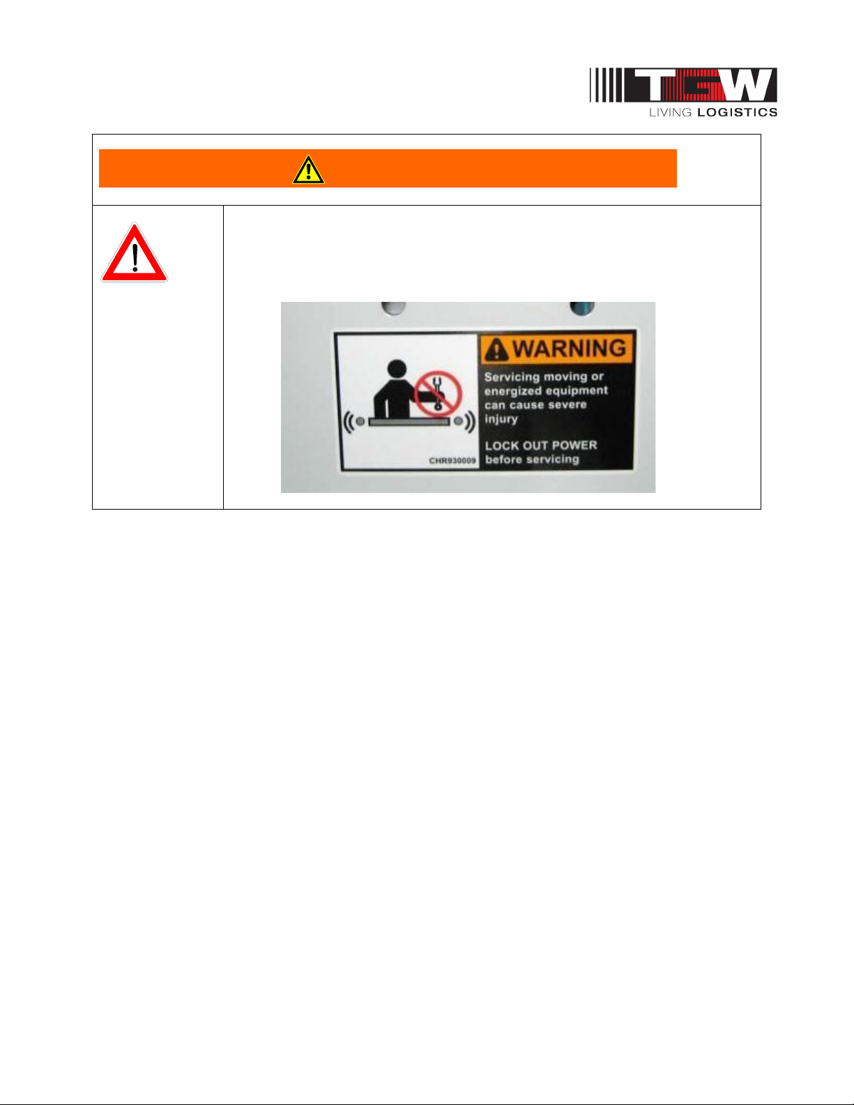
• Before servicing or performing any work in the motor control panel, disconnect
and lock out air and the main incoming service. If only the panel disconnect is
off, the incoming side will still be hot.
P/N: 1193974 Revision Date: 4/25/2019 Page 11 of 83
Page 12

NBS®90 PolySort & SP IOM
3.4: TGW SYSTEMS CONVEYOR CONTROLS SAFETY GUIDELINES
The following basic conveyor control safety guidelines are recommended by TGW Systems even
though Business Partner may or may not purchase conveyor controls from TGW Systems. The items
listed deal with applications of controls equipment. The actual installation of the equipment must
always follow the National Electric Code and all other local codes.
Start-up Warning Horn
Ideally, all conveyors should be within sight of the conveyor start pushbutton. This allows the operator
to verify that no one is touching the conveyor or would be in danger if the conveyor were to start up.
If it is not possible to see the entire conveyor being started from the start pushbutton location, then
some form of audible warning device is required. It could be a horn, buzzer, bell, or anything unique to
that conveyor for that location. It should be loud enough to be heard at any point on the conveyor
system. It should sound for approximately five seconds after the start pushbutton is pushed, prior to the
actual running of conveyor. Any auxiliary equipment such as vertical lifts, turntables, etc., should also
be included in the warning circuitry.
Conveyors that stop and restart under automatic control could also require a horn warning prior to
restarting. If it is not easy to distinguish the difference between a fully stopped conveyor system and a
momentarily stopped conveyor section, then it is advisable to add a warning horn. All conveyor sections
that stop and restart automatically should be marked with appropriate signs or labels.
Start Pushbuttons
Start pushbuttons should be the flush type or guarded such that inadvertently leaning against them will
not actuate the conveyor. They should be provided with a legend plate clearly defining which conveyors
will be started.
Stop Pushbuttons
Stop pushbuttons should be the extended type such that any contact with it is sufficient to stop the
conveyor. They would also be provided with a legend plate clearly defining which conveyors will be
stopped.
Operator Controls
Additional operator controls should be designed into the system with the same guidelines that go into
start and stop pushbuttons, depending upon their function. Devices which are repeated on multiple
control stations, such as emergency stops, should be located at the same relative location on each
station (such as lower right corner).
Emergency Stops
All locations where an operator must work directly at the conveyor should be protected by an
emergency stop. An operator should not have to move from where he is to actuate the emergency stop.
Conveyors in areas of high pedestrian traffic should also be protected by emergency stop devices.
For all other instances, emergency stops should be located throughout a system such that it is possible
to shut down the system without having to walk too far. In these instances the emergency stop is used
more to protect the equipment from damage than to protect personnel.
Emergency stops can be of the pushbutton or cable operated switch type. The pushbutton type should
be a red, mushroom head maintained pushbutton which requires resetting after it is actuated. Cable
operated switches should trip by pulling the cable, and require resetting at the switch.
P/N: 1193974 Revision Date: 4/25/2019 Page 12 of 83
Page 13

NBS®90 PolySort & SP IOM
Actuating an emergency stop must drop-out the start circuit, requiring restarting the system using the
start pushbuttons provided.
An emergency stop should normally stop all conveyors in the system. Very large systems may involve
dividing a system into zones of control based on proximity of personnel, safety hazards, walls
obstacles, etc.
Controls Logic
Solid state controls logic devices, such as programmable controllers are used extensively for conveyor
control. They are very reliable, but a hardware failure or software bug would cause an output to function
erratically. For this reason, start circuits, warning horn circuits, and emergency stops should usually be
configured using conventional relay logic.
Safety Switches
All conveyor control cabinets and motors should be provided with safety (or disconnect) switches.
These switches must have provisions for padlocking. As required for maintenance, equipment should
be locked in the off position.
Special Devices
Special devices and equipment such as vertical lifts, turntables, high speed conveyors, etc., all have
unique design and safety requirements. These should be looked at in each case to determine what the
requirements might be.
Rev 08/22/2011
P/N: 1193974 Revision Date: 4/25/2019 Page 13 of 83
Page 14

NBS®90 PolySort & SP IOM
Definition of Terms
KEY WORD
ABBREVIATION
DESCRIPTION
ALUMINUM RAIL
AR
Original NBS UHMW belt guide holders
AIRBAG
Inflatable lifting device used in NBS30, NBS90, & NBS90
PolySort
BEARING
BRG
Low friction rotating or sliding device
BEAR RAIL
BR
NBS-BR belt guides composed of small ball bearings between
BELT
BLT
Flexible load carrying surface or O-ring
BETWEEN-FRAME
BF
The distance between conveyor side frames
BRACKET
BRKT
Attachment between a main and another part
CHANNEL
CH
Structural side member of conveyor equipment
CONNECTOR
CONN
Holds two parts together (Mechanical or Electrical)
CONSTRUCTION ORDER
CO _ _ _ _ _
Item number of modified standard
CROSSMEMBER
XM
Holds channels apart
DIVERTER
NBS30, NBS90, or NBS90 PolySort. Module
DRIVE
DR
Power unit at the discharge end of NBS sorter
ELEVATION
EL
Top-of belt height above base surface
ENCODER
Electrical distance counter used to track package location along
END PULLEY
E-PULL
4” or 5" diameter roller at charge end of NBS sorter
EXTRUSION
Aluminum base that holds UHMW belt strips (See ALUMINUM
FEET PER MINUTE
FPM
Speed sorter belts are traveling
FILTER / REGULATOR
Combination air pressure air filter / regulator
FLOOR STAND
FS
Name for conveyor bed support
FLOW CONTROL
Needle valve used to control airflow
GEARMOTOR
GEARMTR
One piece gear-reducer motor assembly
GUARD RAIL
GR
Angle or channel used to keep product on NBS
GUARD
GRD
Any part used to protect area for safety reasons
IDLER
IDL
Un-driven pulley used as a tensioning device
ITEM NUMBER
IT #
TGW Systems part identification number
KEY
Square locking device used on rotating shafts
KIT
Group of several parts with a single item number
LACED
LCD
The condition of a correctly installed lacing
LACING
Type or method of joining belts together (splice)
LIFT FRAME
The lifting structure of a NBS90 transfer
LIFT TABLE
Assembly that guides the NBS30 wheels upward
LOCKNUT
Self-locking fastener that resists vibration
LOCTITE
A thread-locking adhesive that resists vibration
3.5: DEFINITION OF TERMS
steel side rails
the sorter length
RAIL)
P/N: 1193974 Revision Date: 4/25/2019 Page 14 of 83
Page 15

NBS®90 PolySort & SP IOM
Definition of Terms
KEY WORD
ABBREVIATION
DESCRIPTION
LOOSE PARTS
LP
Individual parts that must be installed in the field
MODULE
MOD
A self-contained mechanical assembly
MOUNT
MNT
Part used to hold another, similar to a bracket
MOUNTING
MTG
Location and fasteners to attach a mount
MOTOR
MTR
Rotational power source usually using electricity
MUFFLER
Device used to reduce the noise of exhausted air
NATIONAL PIPE THREAD
NPT
Standard identifier for USA tapered pipe sizes
ORDER NUMBER
11 _ _ _ _ _
Original factory order / tracking number
O-RING
Polyurethane cord belts of differing lengths
PHOTOEYE
PE
Optical sensing device used for product control
PLATE
PL
Flat piece of metal usually bolted on for strength
PROGRAMMABLE LOGIC
PLC
Self-contained programmable control unit that can control several
PULLEY
Roller described by diameter and body length
REFLECTOR
RF
Target used to reflect a light back to a photo eye
REGULATOR
REG
Air device that reduces pressure to usable level
ROLLER
Described by axle size and BF dimension
SCANNER
A device that recognizes products by bar codes
SCHEMATIC
Line drawing of a electrical or pneumatic circuit
SEAL
Sealing device on a rotating shaft or cylinder rod
SHAFT
Round steel rod described by diameter and length
SHEAVE
A grooved disc that guides a V-belt or O-ring
SHIM
Thin piece of metal, used to fill up a space
SKATEWHEEL
SKW
2” diameter X 5/8” wide X ¼” axle hole roller
SOCKET
SOC
Hex shaped hole in an Allen screw
SOLENOID
SOL
An electrically operated multi-position air valve
SPACER
Thick washer or tube that a fastener passes thru
SPLICE
Area where similar materials are joined together
SPRING
SPR
Coiled wire device used for un-powered return
SPROCKET
SPKT
Wheel with shaped teeth that engage roller chain
SPUR
Transition bed between a diverter and exit lane
STANDHEAD
Pivoting bracket that attaches support to the bed
STARTER
Electrical relay that energizes the drive motor
TAG
Number that identifies unit in system lay-out
TAKE-UP
Assembly used to remove slack from a belt / belts
TEE
A part with three connections locations
TENSIONER
A pneumatic, spring, or static take-up device
TRANSFER
TRNS
NBS90 and NBS-SP module
CONTROLLER
input and output devices
P/N: 1193974 Revision Date: 4/25/2019 Page 15 of 83
Page 16

NBS®90 PolySort & SP IOM
Definition of Terms
KEY WORD
ABBREVIATION
DESCRIPTION
ULTRA HIGH
UHMW
Industry standard term for the hard milky white Polyethylene used
VALVE
An air shut-off or switching device
VENT
Small hole in gearbox to allow air expansion
WEARSTRIP
Low-friction material used to reduce rubbing wear
WELDMENT
WLDMT
Any part that requires welding in its manufacture
VFD
VFD
Variable Frequency Drive for motor speed control
MOLECULAR WEIGHT
in wear strip applications
3.5.1: Product Description Examples
For the most current list of “Product Description” and “Terms and Abbreviations” Log into
https://www.tgw-conveyor.com/
and select Support/Engineering Support Documents.
P/N: 1193974 Revision Date: 4/25/2019 Page 16 of 83
Page 17
NBS®90 PolySort & SP IOM
WARNING
Chapter 4: NBS®90 POLYSORT APPLICATION GUIDELINES
NBS90 PolySort Selection
Due to the high degree of polybag variance and physical characteristics of typical contents (e.g. pliable,
irregular, light, loose, etc…) it is vital for the Systems Integrator to fully understand the physical
parameters of all conveying products and how well it should perform for the full product range expected
to convey. It remains the responsibility of the Systems Integrator to ensure that the equipment
proposed is capable of handling the products in the manner desired.
The Polysort unit is designed specifically with polybag handling in mind, as shown by the
following features:
• Transfer Tubs have extra high lift and drop above/below the conveying surface by 1/2” to allow
for loosely packed polybags.
• Belts and Divert Rollers are on tighter 2-1/2” centers to help support pliable or irregular
products
• High friction Divert Rollers stop and convey polybags quickly “on the fly”
o Note for Carton Handling:
The high friction surface can cause higher center of gravity products to tip at
high speeds and rates. Generally, products convey well if the center of gravity
is no more than 25% of product width or height. Consult with Applications
Engineering for your specific application.
• Transfer Tubs use high performance SEW Movimot drive motors for quick response and high
efficiency
• Bed Rail connections and infeed points are rounded and scalloped to reduce product snagging
• Divert Tubs are fitted with infeed ramps between each lane to minimize snagging and
maximize rate
• Small Array Photo Eyes are used to sense products 5mm thick
Given the above design features, the nature of conveying products with irregular or loose conveying
surfaces are not guaranteed. TGW has tested a wide range of products contained in polybags with
successful convey with the vast majority of “normal” industry packaged polybags from companies in the
Apparel, Postal/Parcel, and Distribution markets.
Consult with TGW Applications Engineering for your specific needs or to arrange product
testing.
P/N: 1193974 Revision Date: 4/25/2019 Page 17 of 83
• Post sort orientation may not be maintained. Typical divert is onto a
chute, bin, tub or similar. Consult with TGW Applications Engineering for
specific details or to arrange product testing.
Page 18
NBS®90 PolySort & SP IOM
CAUTION
Use NBS90 PolySort when:
• Tighter belt centers than our standard NBS is required
• Product may be same size and weight, or mixed
• Product weight: less than 2oz. – 40 lbs. Max, 1,000 lbs. total live load
• Products typically convey onto chute or dump into tote, Gaylord, or similar
• Ambient temperature is +35° to 100°F
NBS90 PolySort Application Notes:
• Matching conveyor rates before and after NBS sortation are vital to proper application decisions.
• If orientation integrity is required post transfer, products would need to be tested.
• The transfer exit lanes from NBS90 PolySort can be gravity roller (used as a deceleration area),
chutes or powered conveyor run at a speed which allows the lane to receive products as fast as
they are transferred.
• The maximum divert rate for a NBS90 PolySort single-direction is 50 CPM. The bidirectional
rate is 50 CPM. (Contact the Customer Support group for application consideration above
these rates)
• Induction to NBS90 PolySort sortation must be able to singulate individual products. Minimum
induction gap varies with line speed and determine product pitch.
o Speed / Pitch = Rate. Reference chart example below.
PolySort Rate w/Max Polybag
Speed (FPM) Min Gap
(ins)
300 44 28 72 50
High rates are possible given ideal product size and type, edge aligned and induction control upstream
of PolySort, and programming optimization. Consult with TGW Applications Engineering for
specific details or to arrange product testing.
• To increase rate justify all products along the exit lane side of the NBS90 PolySort sortation for
single direction transfer.
• When NBS90 PolySort over-all-length is over 50' and up to 100' in length, an addition auxiliary
air take-up is required.
• The maximum length of a NBS90 PolySort sortation conveyor, including two air take-up units, is
100'.
Max Prod Load
(ins)
Pitch (ins) Max Rate
(CPM)
• The use of a VFD (Variable Frequency Drive) or at least a "soft start" motor drive is
recommended for NBS90 PolySort drive motor control. Ignoring this point may void the motor
warranty.
• The use of a VFD (Variable Frequency Drive) is required for NBS drive motor control. Ignoring
this point will void the belt motor manufacturer’s warranty.
P/N: 1193974 Revision Date: 4/25/2019 Page 18 of 83
Page 19

NBS®90 PolySort & SP IOM
NBS90 PolySort Elevation Top of Belt
The minimum elevation at the discharge end of an NBS90 PolySort sortation line is 19". The end drive
unit is located at the discharge end and requires a space of 60" or 33” long.
Extra room alongside the drive should be provided to allow maintenance personnel access to either
side of the drive assembly. In order to remove air take-up from bottom side of conveyor, add 6” of
clearance and 7” for transfers.
NBS90 PolySort Transfer Locations
• The leading edge of the first transfer module must be a minimum of 11 1/8" from the charge end
of the sorter.
• The trailing edge of the last divert module must be at least 11 1/8" from the discharge end.
• The center line of a transfer exit lane is centered on the center line of the transfer rollers in an
NBS90 PolySort.
• Standard available coated transfer rollers widths are: 25 1/2"
• One NBS90 PolySort transfer can transfer to up to four separate lanes of 1/2 the width of the
roller length.
• Single direction transfer to two lanes is called a "Dual Transfer"
• Bi-directional transfer to two lanes each side is called a "Quad Transfer"
NBS90 PolySort Standard Available Selections
• Horse Power (HP)
o 2HP, 3HP, 5HP
• Feet Per Minute (FPM)
o 120, 210, 240, 270, 300
NBS90 PolySort Sorter Nominal Widths & Number of Belts
• 26.5 NBS90 PolySort with 9 Belts on 2-1/2" Centers
Features and benefits
FEATURES: BENEFITS:
Tighter belt centers vs standard NBS90 Prevents polybags from sagging between belts
Extra high/low transfer lift Keeps polybags from dragging or snagging
High friction natural rubber transfer rollers Maximum grab on a slippery polybag
High powered SEW transfer motor Powerful acceleration for polybag transferring
Direct drive 97% efficient gearmotor on sorter
drive
Eliminates all chain or drive belt maintenance
Individual belt take-ups Even belt tension for unequal stretch or length
Use with extreme range of mixed product from
2oz. to 40lbs.
Adaptable to a wide range of customer needs
P/N: 1193974 Revision Date: 4/25/2019 Page 19 of 83
Page 20
NBS®90 PolySort & SP IOM
CAUTION
Chapter 5: NBS®90 SP (SMALL PARCELS) SELECTION GUIDELINES
Use NBS®90 SP When:
• Higher speed sortation then NBS is required
• Product may be same size and weight, or mixed
• Product weight: 1-20 lbs, 1000 lbs. total load
• Product size: 4" X 4" Min. -- 13" X 24" Max.
• Ambient temperature is +35° to 100°F
NBS90 SP Applications
• Matching conveyor rates before and after NBS sortation are vital to proper application decisions.
• The transfer exit lanes from NBS SP can be gravity roller (used as a deceleration area), chutes
or powered conveyor run at a speed which allows the lane to receive products as fast as they
are transferred.
• The maximum divert rate for a NBS SP single-direction is 120 CPM. The bidirectional rate is
120 CPM. (Contact the Customer Support group for application consideration above these
rates)
• Induction to NBS-SP sortation must be able to singulate individual products. Minimum gap of
6"+ conveyor width at 250 FPM 10"+ conveyor with at 300 FPM.
• Justify all products along the exit lane side of the NBS SP sortation for single direction transfers.
• When NBS-SP over-all-length is over 50' and up to 100' in length, an addition auxiliary air take-
up is required.
• The maximum length of a NBS SP sortation conveyor, including two air take-up units, is 100'.
• All units require 1/2” gap before and after the unit for maintenance access to the end covers.
• The use of a VFD (Variable Frequency Drive) or at least a "soft start" motor drive is
recommended for NBS90 SP drive motor control. Ignoring this point may void the motor
warranty.
• The use of a VFD (Variable Frequency Drive) is required for NBS drive motor control. Ignoring
this point will void the belt motor manufacturer’s warranty.
NBS SP ELEVATION TOP OF BELT
The minimum elevation at the discharge end of an NBS SP sortation line is 23". The end drive unit is
located at the discharge end and requires a space 23" high by 33" long.
Extra room alongside the drive should be provided to allow maintenance personnel access to either
side of the drive assembly. In order to remove air take-up from bottom side of conveyor, add 6” of
clearance and 7” for transfers.
P/N: 1193974 Revision Date: 4/25/2019 Page 20 of 83
Page 21

NBS®90 PolySort & SP IOM
NBS90 SP Transfer Locations
• The leading edge of the first transfer module must be a minimum of 28" from the charge end of
the sorter.
• The trailing edge of the last divert module must be at least 42" from the discharge end.
• The center line of a transfer exit lane is centered on the center line of the transfer rollers in an
NBS SP.
• Standard available coated transfer rollers widths are: 9", 12", 15", 18", & 21"
• One NBS SP transfer can transfer to up to four separate lanes of 1/2 the width of the roller
length.
• Single direction transfer to two lanes is called a "Dual Transfer"
• Bi-directional transfer to two lanes each side is called a "Quad Transfer"
NBS SP Standard Drive Selections
• Horse Power (HP)
o 5, .75, 1, 1.5 HP @ the following speeds
• Feet Per Minute (FPM)
o 120, 150, 180, 200, 220, 250, 300 FPM
o Additionally: 2 HP @ 200, 220, 250, 300 FPM
NBS SP Sorter Nominal Widths & Number Of Belts
• 11.5NBS-SP with 3 Belts on 2-1/2" Centers
• 14 NBS-SP with 4 Belts on 2-1/2" Centers
FEATURES: BENEFITS:
High speed sortation of small product Maximize throughput
Reversible diverter drive Divert right and left, saving space
High friction transfer rollers Positive acceleration and maximum divert rate
Pick up product “on-the-fly” Maximize sort rate
Product is conveyed on belts until sorted Increased accuracy of control tracking
Compact design of divert module Close center of divert points
Individual belt take-ups Long belt life and reduced maintenance
P/N: 1193974 Revision Date: 4/25/2019 Page 21 of 83
Page 22
NBS®90 PolySort & SP IOM
CAUTION
Chapter 6: NBS RECEIVING & SITE PREPARATION
General
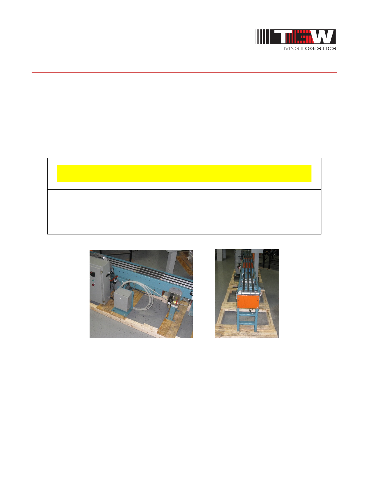
TGW Systems NBS Narrow Belt Sorters are shipped in subassemblies. These subassemblies are
packaged to guard against damage in shipment, when handled properly.
Examination immediately following unloading will show if any damage was caused during shipment. If
damage is evident, claims for recovery of expenses to repair damage or replace components must be
made against the carrier immediately. While unloading, a check must be made against the Bill of
Lading, or other packing lists provided, to confirm full receipt of listed items.
• TAKE CARE DURING THE REMOVAL OF EQUIPMENT FROM THE CARRIER.
Remove small items and boxes first. Pull and lift only on the skid, not on the frame,
crossmember or any part of the equipment. Be sure the skid is free of other
materials which may be on top of or against the side of the skid to be removed.
Preparation of Site
After the conveyor is received, move it to the installation site or designated dry storage area as soon as
possible. Clean up all packing material immediately before parts get lost in it. Loose parts should
remain in the shipping boxes until needed.
Prior to starting assembly of the conveyor, carefully check the installation path to be sure there are no
obstructions that will cause interference. Check for access along the path needed to bring in bed
sections and components closest to the point where they are needed. It is often necessary to give the
area along the system path a general cleanup to improve installation efficiency, access and accuracy.
P/N: 1193974 Revision Date: 4/25/2019 Page 22 of 83
Page 23
NBS®90 PolySort & SP IOM
CAUTION
6.1: NBS PARTS INVENTORY & IDENTIFICATION
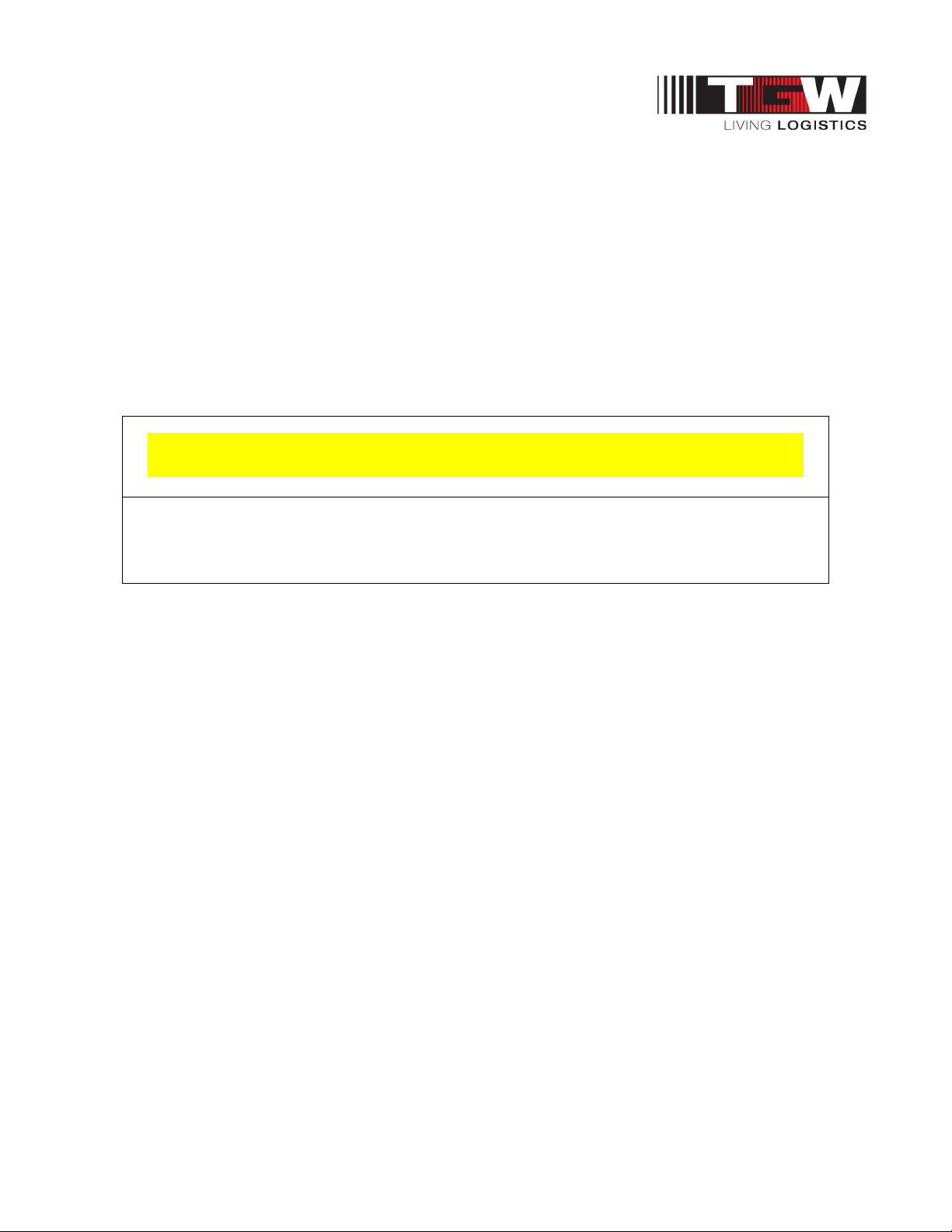
Each subassembly is shipped completely assembled except the bed joint splice plate/nuts which are
shipped with other loose parts. Identify and separate the sorter subassemblies by type or tag number,
for inventory and ease of locating during installation.
An identification label is attached to the inside of one side channel or on a crossmember, close to one
end of each conveyor bed. This label contains job number, part number, order number, tag number (if
specified), assembler's initials and date of manufacture. On supports, the tag is located on the bottom
side of the foot. On special devices, it is located on a convenient flat surface that is not offensive to the
appearance of the equipment but is still accessible for viewing. These numbers can be crossreferenced against the packing list. The illustrations in this manual and the part number stickers will
assist you with your inventory.
• Do not remove finishing nails from rail ends. They keep the UHMW guides from sliding
down to the discharge end.
P/N: 1193974 Revision Date: 4/25/2019 Page 23 of 83
Page 24
NBS®90 PolySort & SP IOM
Chapter 7: NBS PARTS INVENTORY & IDENTIFICATION
The following procedures are to be used as guidelines only. Specific installation methods will vary
somewhat depending on available equipment on site and each installer's preferences based on past
experience.
Each subassembly is shipped completely assembled except the bed joint
splice plate/nuts which are shipped with other loose parts. Identify and
separate the sorter subassemblies by type or tag number, for inventory
and ease of locating during installation.
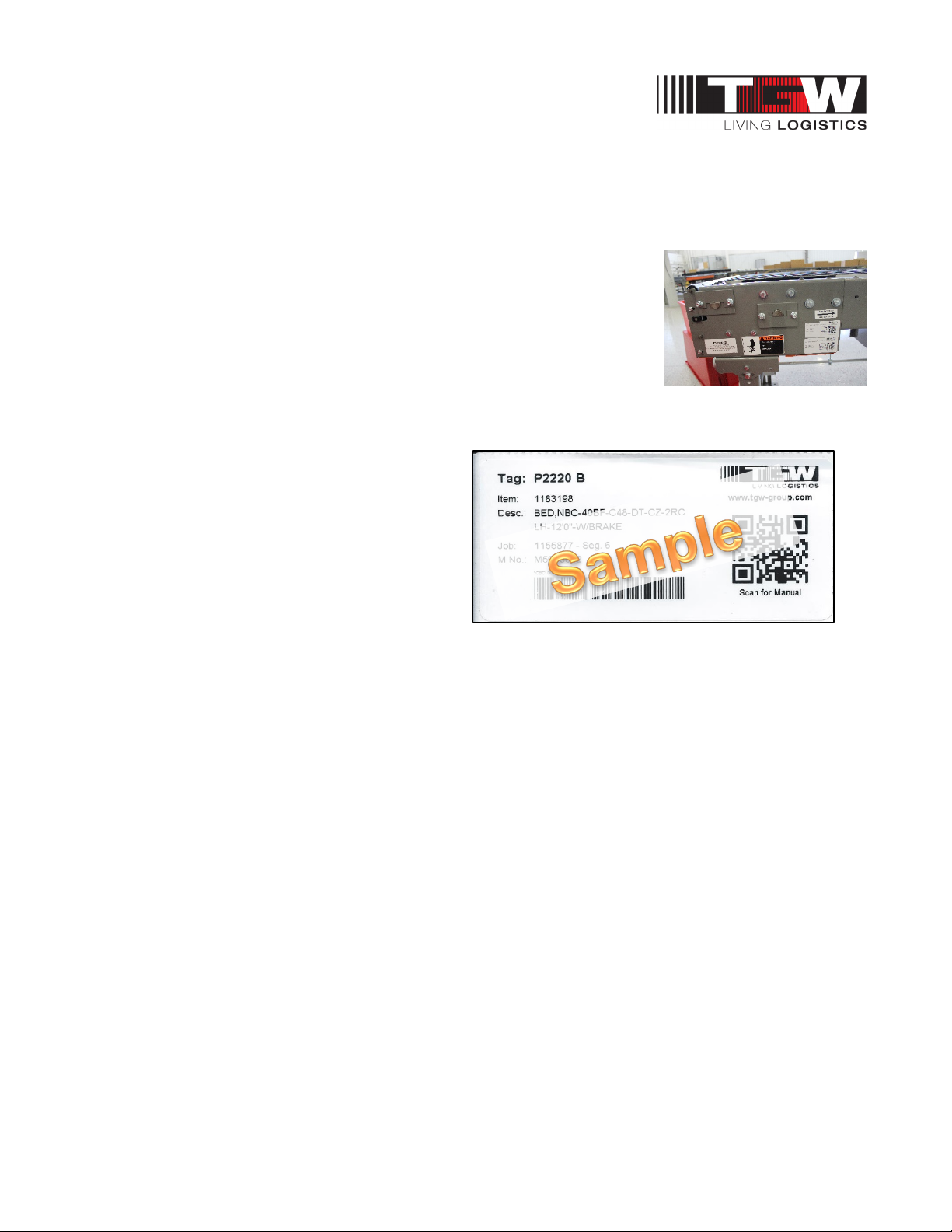
An identification label is attached to the inside of one side channel or on a
crossmember, close to one end of each conveyor bed.
This label contains:
• Item number
• Description
• Job Number
• Mfg. Number
• Date of manufacture
• Tag number (if specified)
• Assembler's clock number
• QR (Quick Response) Label
o Scan Code For IOM Manual
Scan the QR code to retrieve the IOM Manual, if nothing happens; check your scanner settings and
make sure the QR Label setting is enabled.
On the supports, the tag is located on the bottom side of the foot. On special devices, it is located on a
convenient flat surface that is not offensive to the appearance of the equipment but is still accessible for
viewing. These numbers can be cross-referenced against the packing list. Loose parts are boxed and
shipped separately.
You should have all conveyor sections and supports for a particular conveyor prior to installation. It is
cost-effective to identify and procure any missing parts before they are needed for assembly. Small
items like nuts and bolts are weigh-counted and packaged by size and type.
P/N: 1193974 Revision Date: 4/25/2019 Page 24 of 83
Page 25
NBS®90 PolySort & SP IOM
WARNING
WARNING
Chapter 8: NBS INSTALLATION DETAILS
General Procedures
The following procedures are to be used as guidelines only. Specific installation methods will vary
somewhat depending on available equipment on site and each installer's preferences based on
experience.
Dimensional Reference Points
The path of each conveyor in the system is determined by establishing a reference point at each end.
The centerline of the conveyor is established and a chalk line is snapped between these points.
Conveyors should be installed with the centerline of the bed matching the centerline of the conveyor
path within 1/16" of true center. Locate and mark the center of the crossmembers at each end of the
conveyor. Use a plumb line or other applicable device to ensure accuracy to the chalk line.
Always carry out a thorough check for any obstructions such as building columns, manholes, etc. It may
be necessary to reroute the conveyor to avoid the obstruction. In this case it would be advisable to
begin installation at this point, using the obstruction as a reference point (Datum), and install the
sections in either direction as required.
All conveyor sections must be checked for squareness prior to installation as "racking" or being
knocked out of square may have occurred during shipping and handling.
• The Installation Supervisor must be experienced with conveyor and
qualified in the mechanics of the equipment and enforce safe
working procedures for the protection of the crew, customer, and
customer's property.
• Before restarting a conveyor which has been stopped because of an
emergency, an inspection of the conveyor must be made and the
cause of the stoppage determined. The starting device must be locked
out before any attempt is made to correct the cause of stoppage.
P/N: 1193974 Revision Date: 4/25/2019 Page 25 of 83
Page 26
NBS®90 PolySort & SP IOM
WARNING
WARNING
8.1: NBS GENERAL ELECTRICAL REQUIREMENTS
• All electrical controls must be installed, wired, and connected
by a licensed electrician only.
• All motor controls and wiring must conform to the National
Electrical Code as published by the National Fire Protection
Association and approved by the American National Standards
Institute, Inc. In addition, since specific electrical codes vary
from one area to another, be sure to check with the proper
authorities before starting the electrical wiring.
The electrical voltage of the motor will be stamped on the metal nameplate. This voltage should be
checked to see that it matches your available voltage. Many motors, both single phase and three
phase, are dual voltage. Consult the wiring diagram on the motor for the proper connections. If a threephase motor on a single direction conveyor runs the wrong direction, two of the three leads must be
switched to reverse rotation.
• Do not connect the motor to any other voltage than stamped
on its metal nameplate.
Consult the wiring diagram on the inside cover of the starter and push-button station for the proper
electrical connections.
Three-phase drives require transformers to reduce the push-button and control circuit to 115 volts. If
primary voltage is changed, the transformer must be changed according to the wiring diagram found on
the transformer.
Note:
All control equipment is covered by the original manufacturer's equipment warranty.
P/N: 1193974 Revision Date: 4/25/2019 Page 26 of 83
Page 27
NBS®90 PolySort & SP IOM
WARNING
• All safety devices, including wiring of electrical safety devices,
shall be arranged to operate in a “fail safe” manner. That is, if
power failure or failure of the device itself would occur, a
hazardous condition must not result.
• Do not connect the motor to any other voltage than stamped
on its metal nameplate.
NEMA type enclosure ratings are as follows:
NEMA 1 - Indoor use; Provides protection against contact with internal components. Suitable for use in
warehouse and distribution environments.
Gasketed:
NEMA 1 - Same use as NEMA 1, but with additional protection against dust and dirt.
NEMA 3 - Outdoor use, designed to keep out rain and dust.
NEMA 4 - Indoor and outdoor use, designed to keep out rain and dust.
NEMA 12 - Indoor use: Provides protection against dust, dirt and oil, and drippings of noncorrosive
liquids suitable for use in industrial environments.
NEMA 13 - Indoor use: Provides protection against dust, dirt, sprayed oil and noncorrosive liquids.
P/N: 1193974 Revision Date: 4/25/2019 Page 27 of 83
Page 28

NBS®90 PolySort & SP IOM
8.2: NBS90 POLYSORT TGW-ERMANCO CONTROLS GUIDELINES
ECG 7.1
Rev. 1.6.03
(SEW-Eurodrive, 2018)
The SEW-Eurodrive MOVIMOT® is used in many high speed reversing (and non-reversing)
applications, such as the transfer drive for the PolySort. The MOVIMOT® as provided by TGW would
typically consist of the following:
- Three phase induction motor with an integrated variable frequency drive
- Speed control potentiometer, built into drive housing.
- Dynamic braking resistor, preinstalled in the drive.
Additional hardware required for control of the MOVIMOT® would include:
- Lockable, fused disconnect switch for each drive.
- Motor contactor for each system.
- 24V Control Power Supply
®
Motor Circuit Information
- 24VDC PLC output (PNP sourcing) for run command (two for reversing).
High Voltage Connections
- Verify that the motor nameplate rating matches the system voltage and frequency.
- Size fuses as for a conventional induction motor.
- Terminals for 3 phase power are located inside the connection box on the motor.
- Group motor installations are not permitted.
- A contactor before the fused disconnect switches must be used. This should be energized with the
Master Control Relay (MCR) for the system and not used for normal motor stopping.
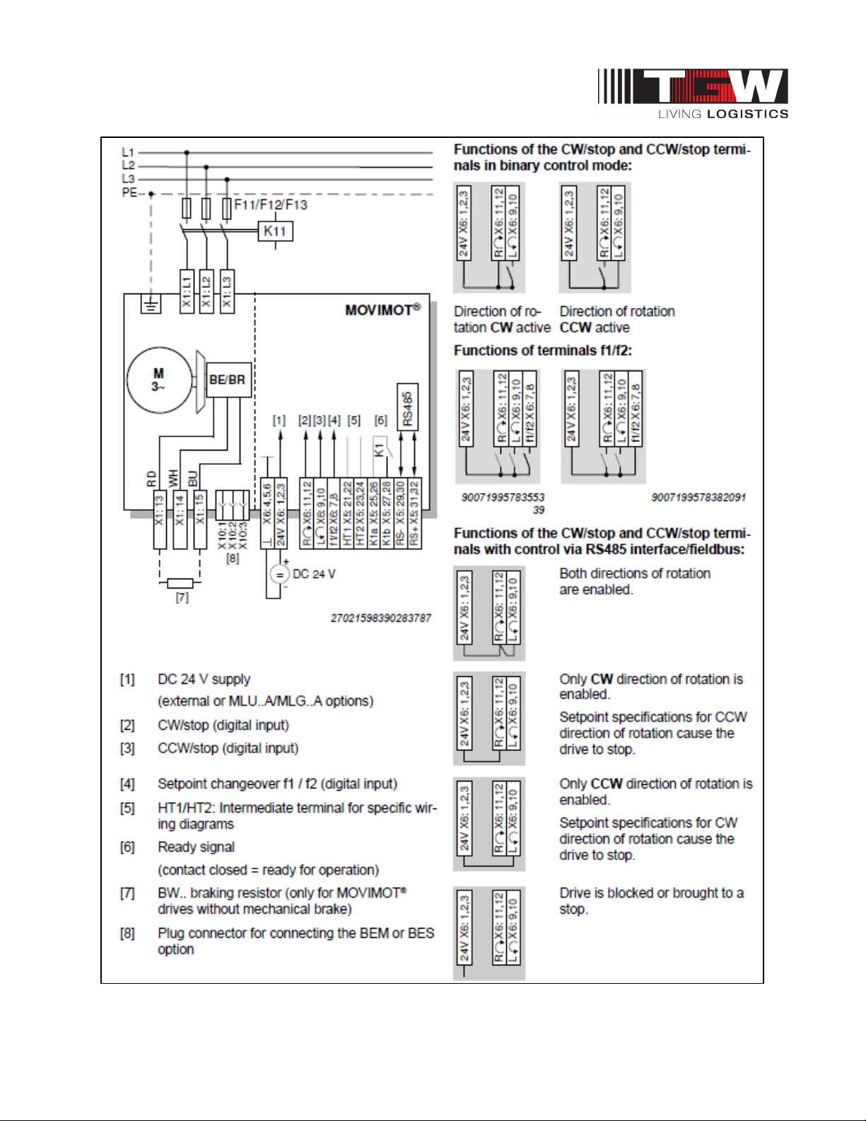
- Connect conductors to the L1, L2, L3 and ground terminals. See figure 1 below.
Controls Connections
- Connect dry contacts between the 24VDC and R⟳ and/or L⟲ terminals. These signals will start and
stop the motor in the clockwise or counter-clockwise directions. See figure 1.
- Connect the external power to the 24V and ┴ terminals. Connect
PLC outputs to the R⟳ and/or L⟲ terminals (PNP sourcing outputs).
P/N: 1193974 Revision Date: 4/25/2019 Page 28 of 83
Page 29
NBS®90 PolySort & SP IOM
P/N: 1193974 Revision Date: 4/25/2019 Page 29 of 83
Page 30
NBS®90 PolySort & SP IOM
Speed, Ramp, and DIP Switch Settings
- The speed of the drive can be adjusted by turning the setpoint potentiometer, f1, accessible through a
screw plug on the connection box cover.
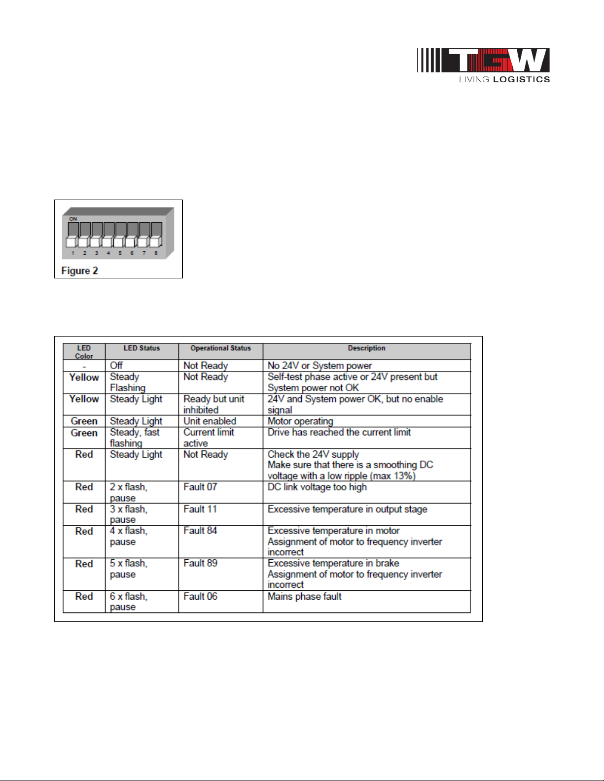
- The ramp time is set with switch t1. Set this to detent position ‘0’ for maximum acceleration.
- DIP switch S1 should have all switches in the off position. (factory default) See figure 2.
- Setpoint switch f2 is not used and can be left at the factory setting.
Status LED
A three-color status LED is visible on the outside of the connection box cover. The table below
describes the function:
P/N: 1193974 Revision Date: 4/25/2019 Page 30 of 83
Page 31
NBS®90 PolySort & SP IOM
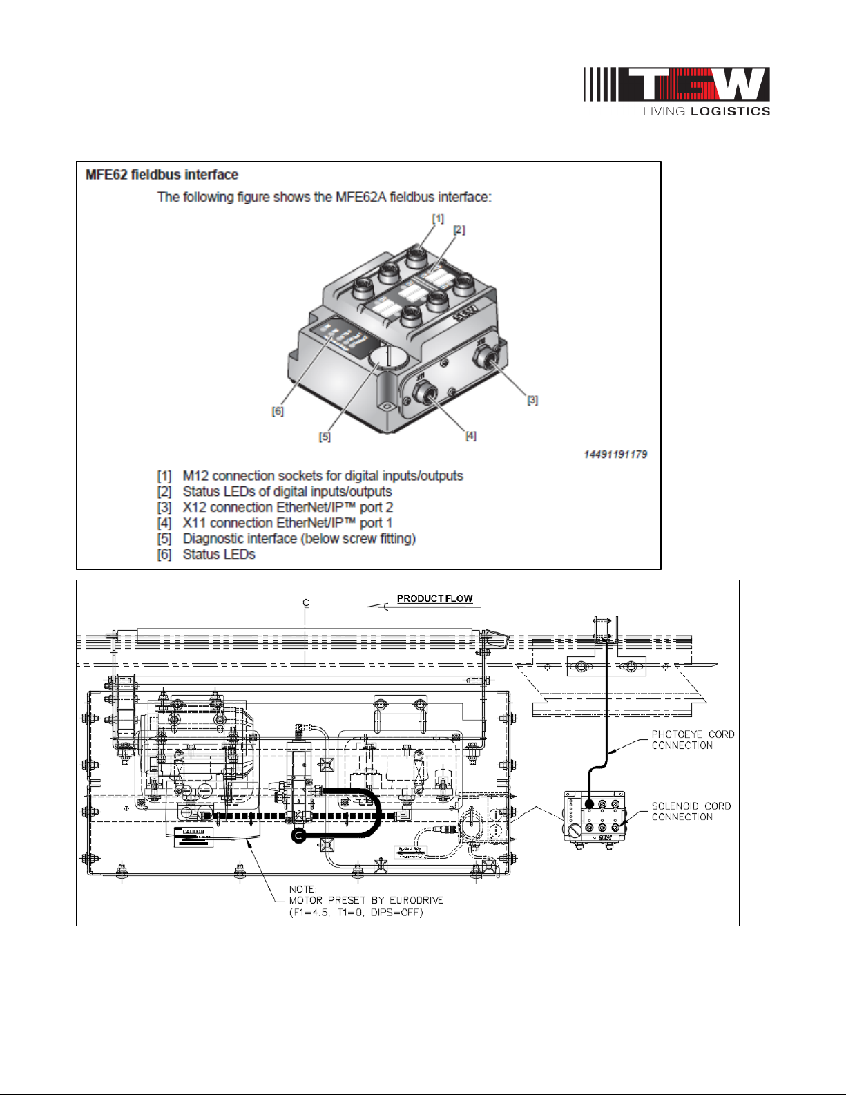
8.2.1: NBS90 PolySort Sorter with Ethernet/IP comes pre-mounted from the factory.
P/N: 1193974 Revision Date: 4/25/2019 Page 31 of 83
Page 32
NBS®90 PolySort & SP IOM
Connection of MFZ21 connection module with MFE62 to MOVIMOT
®
P/N: 1193974 Revision Date: 4/25/2019 Page 32 of 83
Page 33
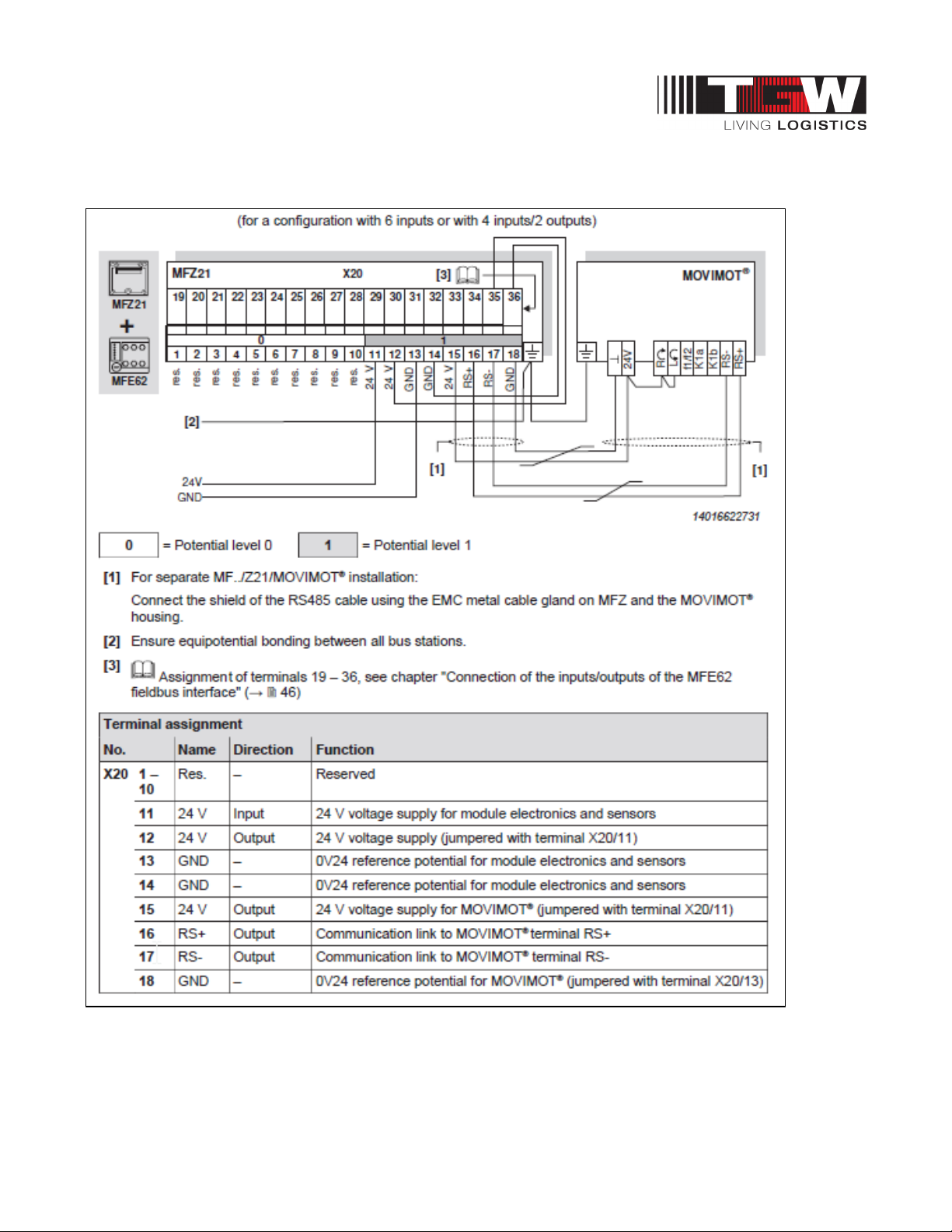
NBS®90 PolySort & SP IOM
(Tri-Tronics, 2016)
MFZ21 connection module with MFE62 EtherNet/IP™ interface MOVIMOT
®
P/N: 1193974 Revision Date: 4/25/2019 Page 33 of 83
Page 34
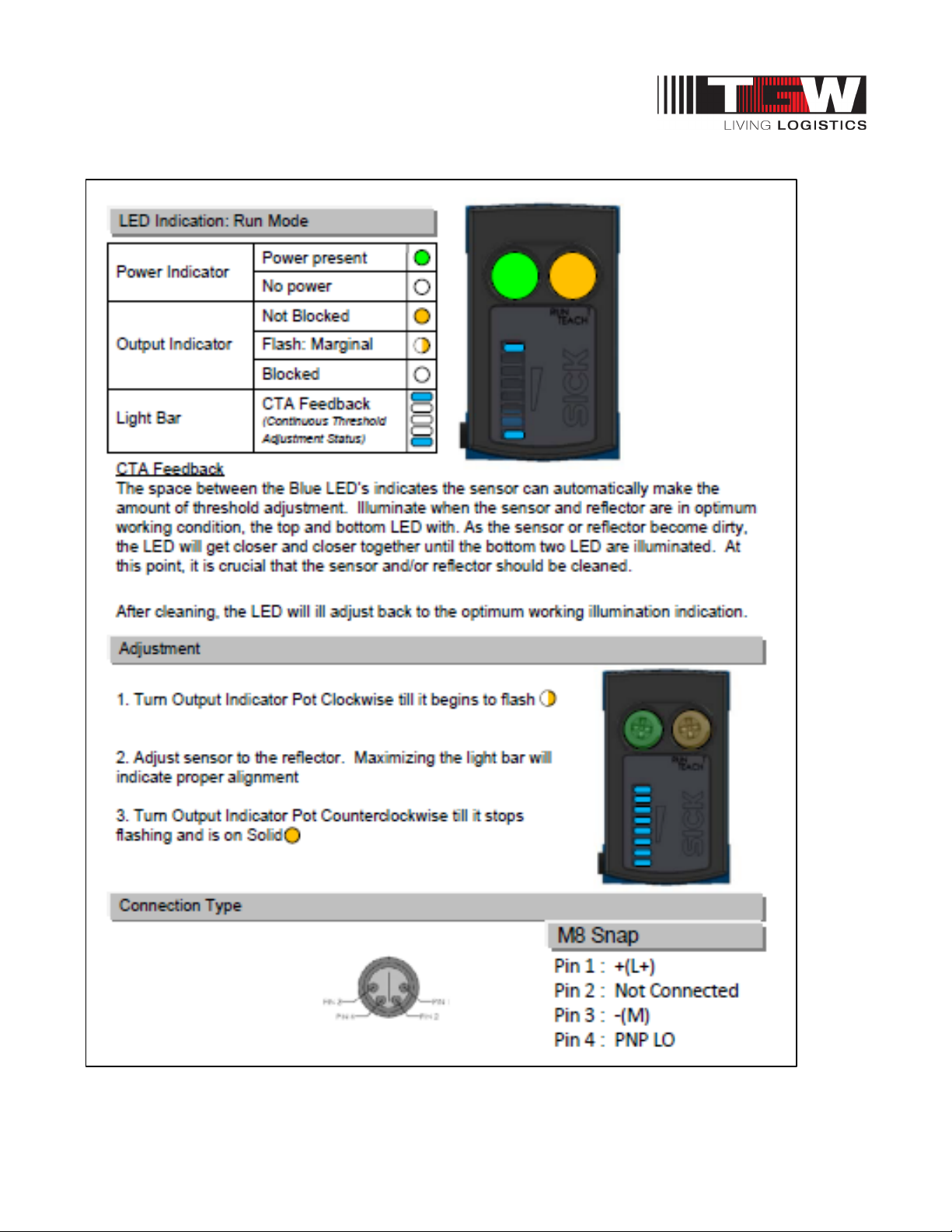
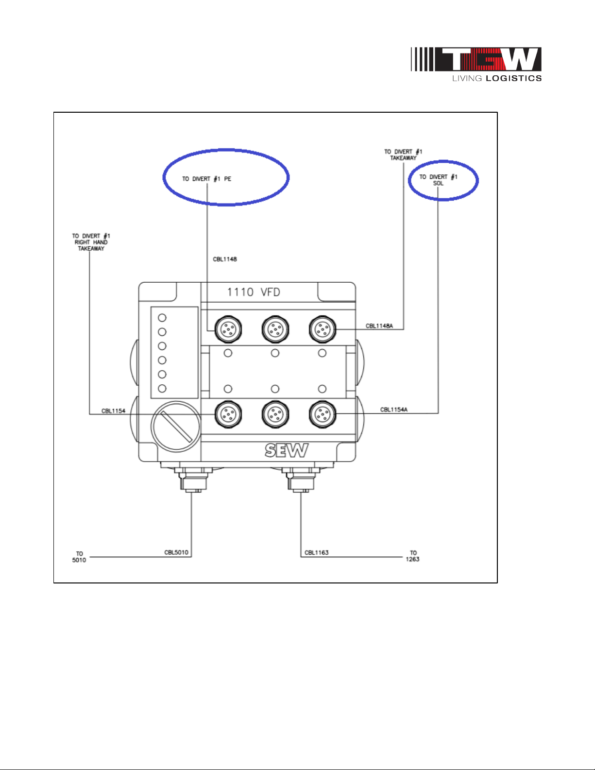
NBS®90 PolySort & SP IOM
Divert #1 PE
P/N: 1193974 Revision Date: 4/25/2019 Page 34 of 83
Page 35
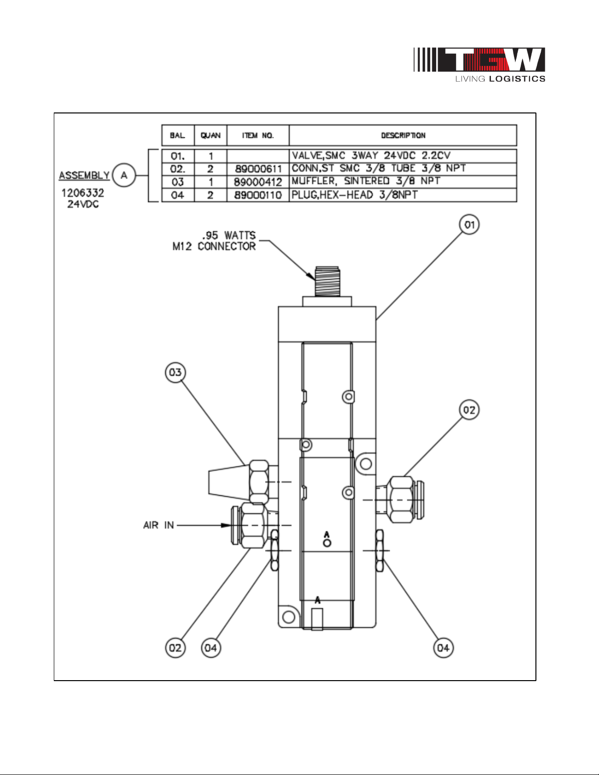
NBS®90 PolySort & SP IOM
Divert #1 Sol
P/N: 1193974 Revision Date: 4/25/2019 Page 35 of 83
Page 36
NBS®90 PolySort & SP IOM
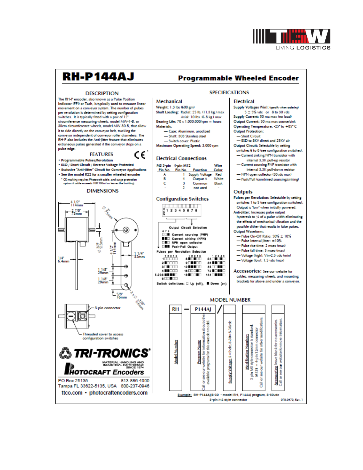
8.2.2: NBS90 PolySort Programmable Wheeled Encoder
P/N: 1193974 Revision Date: 4/25/2019 Page 36 of 83
Page 37
NBS®90 PolySort & SP IOM
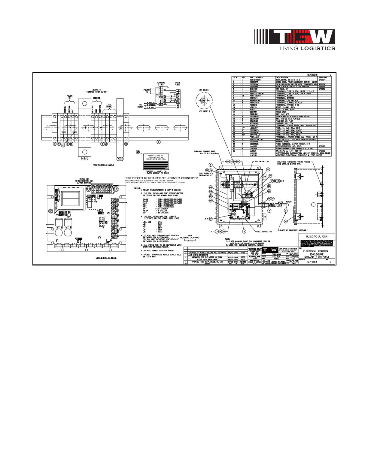
8.3: NBS90 SP ELECTRICAL CONTROL ENCLOSURE
P/N: 1193974 Revision Date: 4/25/2019 Page 37 of 83
Page 38
NBS®90 PolySort & SP IOM
WARNING
8.4: NBS GEAR MOTOR ACTIVATION
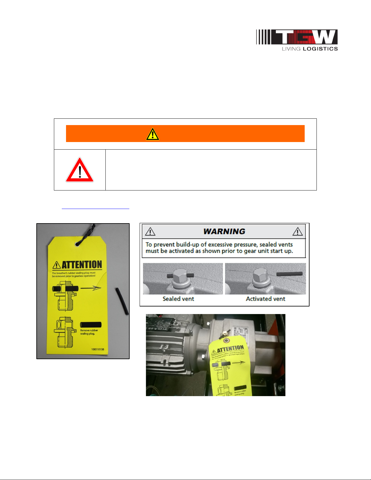
PRIOR to systems activation - Please inspect the gear unit for a vent and if applicable to the product
remove the rubber sealing plug to activate. The vent is designed to allow excessive pressure to escape.
Each gear unit should have a yellow instruction tag as shown below. The tag can be removed after the
plug is removed.
Note: The rubber sealing plug is in place for shipping and storage purpose only.
• In order for the gear motor to release pressure, the vent must be
activated by removing the rubber sealing plug PRIOR to gear unit
start up.
Please check you gear unit for a vent and if applicable to your product, remove the sealing plug to
activate. “https://www5.nord.com
” Operation Manual for Gear Units (B1000).
P/N: 1193974 Revision Date: 4/25/2019 Page 38 of 83
Page 39
NBS®90 PolySort & SP IOM
Note:
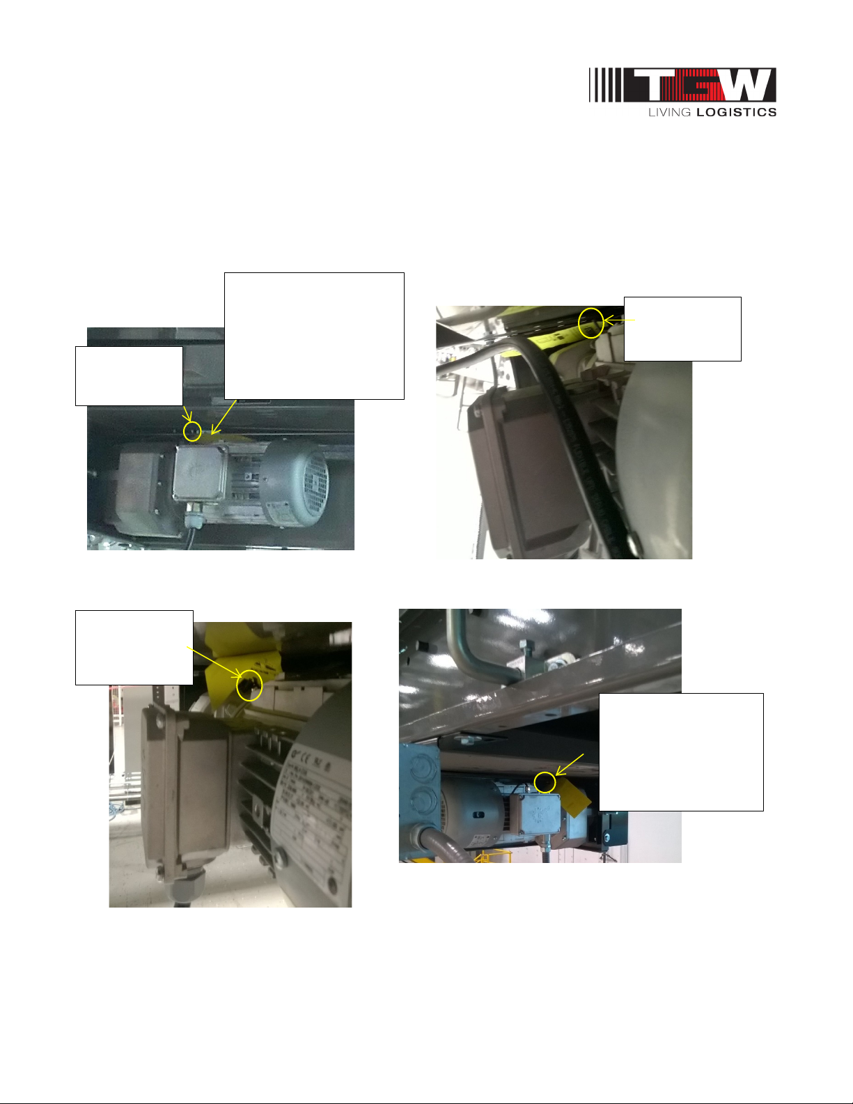
Yellow tags may be tucked out of sight. Please inspect all motors for a vent and remove sealing plug, if
present, to activate.
The following pictures are examples showing where vent plugs may be located depending on the
product line and motor position.
The Yellow Tag may be
Sealing Plug
hidden or possibly
missing. Check motor for
a vent and remove
sealing plug to activate.
Sealing Plug
Sealing Plug
Vent & Sealing Plug
may be hard to see
depending on the
product line and motor
location.
P/N: 1193974 Revision Date: 4/25/2019 Page 39 of 83
Page 40
NBS®90 PolySort & SP IOM
CAUTION
8.5: NBS ELEVATIONS
All top-of-belt (TOB) heights should be installed in accordance with the elevations shown on the
drawings. In addition, all sortation devices must be level across both the frame width and length.
Leveling of the frames is best done using a rotating laser level along the length of the conveyor and a
builder's level across the width.
After the first elevation is established at a critical point, the elevation of all other points shall be relative
to this first point. Normal practice is to dimension the layout and measure elevations from the floor at
each point of support.
As the conveyor system proceeds onto another floor or into another building or room, a new elevation
will be measured from the floor at that point. This new elevation will then become the reference for
subsequent elevations.
When installing an overhead system, the first elevation is measured from the floor and becomes the
reference elevation point until a change in elevation is shown on the layout. Any new elevation is also
measured from the floor and becomes the new reference point. The process is repeated each time an
elevation change occurs.
• Consult the building architect or a structural engineer regarding ceiling loading or
structural limitations of the building if any conveyor is ceiling hung.
8.6: NBS SUPPORTING ARRANGEMENT
Floor Supports
Install bolts used to attach the standhead to the frame so the nut is on the bottom. Standhead bolts
should be left finger tight while the conveyor is being assembled and aligned.
Floor supports are ordered by nominal height range, which is the dimension from the floor to top of the
support. Conveyor elevations are shown on the layout by top-of-belt elevations. The difference between
top of belt (TOB) and top of support is 7-3/8” and 9/58” end pulley and 13 1/16” direct drive bed. This
dimension must be subtracted from the TOB height to set support height.
It is important that conveyor frames be installed level. Floor supports will accommodate normal
irregularities in the floor surface. Adjustment for elevation in floor supports is accomplished with metalon-metal bolt clamping force. To achieve the support's stated load rating, it is necessary to tighten the
elevation adjustment bolts (3/8" diameter) to 23 ft. /lbs. of torque.
Supports should always be installed in the vertical position, and any variations due to conveyor pitch or
floor slope will be compensated for in the pivoting stand-head of the support.
P/N: 1193974 Revision Date: 4/25/2019 Page 40 of 83
Page 41
NBS®90 PolySort & SP IOM
WARNING
8.7: NBS SUPPORTS & CONNECTIONS
For details on Supports & Connections, see Support & Connections IOM (#1200485) at
https://www.tgw-conveyor.com/support/iom-manuals/supports-and-connections
Anchoring
Anchoring in concrete floors is accomplished by drilling into the floor and inserting the suitable anchor
bolt. The hole diameter and depth must be in accordance with the anchor bolt manufacturer’s
instructions, and all applicable codes and requirements.
Anchor intermediate floor supports with two anchor bolts, one through each support foot plate using
minimum 3/8” diameter anchor bolts. Stagger anchors from front hole on one side to rear hole on
opposite side. For floor supports, over 5’ minimum use 1/2” diameter anchor bolts. Anchor bolts for
equipment subject to impact loads should be a minimum of 1/2” diameter or as superseded by any
other applicable code.
• Place a bolt through the frame and support immediately with
finger tight nut. This will prevent the frame from falling off the
Bed/Support Connectors
NBS can ONLY be supported at bed joints. Install the sortation conveyor (drive bed thru end pulley) on
supports. Leave approximately 1/16″ gap between low friction rail joints. The conveyor must be level
and straight. Adjoining beds are connected using 3/8″ thick by 10″ nut plate, 3/16″ thick by 10″ clamping
plate and 3/8″ hardware. These parts are shipped with other loose parts. Insert 10″ nut plate halfway
into the formed channel end of each bed.
Mount standhead support with two 3/8-16 x 1″ hex head bolts with flat and lock washers. After that
mount 10″ clamp plate to channel ends with four 3/8-16 x 1″ hex head bolts with nut, flat and lock
washers (see picture below). It can be seen that a crossmember could be moved into the recessed
area of the standhead support bracket if needed.
Maintaining the rigidity and flatness of the conveying surface is the end result of proper support
installation.
support, if bumped, and causing injury.
P/N: 1193974 Revision Date: 4/25/2019 Page 41 of 83
Page 42
NBS®90 PolySort & SP IOM
CAUTION
10” Nut plate
10” Bed Splice
Stand
Connector
-head
8.8: NBS90 POLYSORT BED CONNECTION KIT
Bed Splice Connection Kit TGW # 1207722
Note:
P/N: 1193974 Revision Date: 4/25/2019 Page 42 of 83
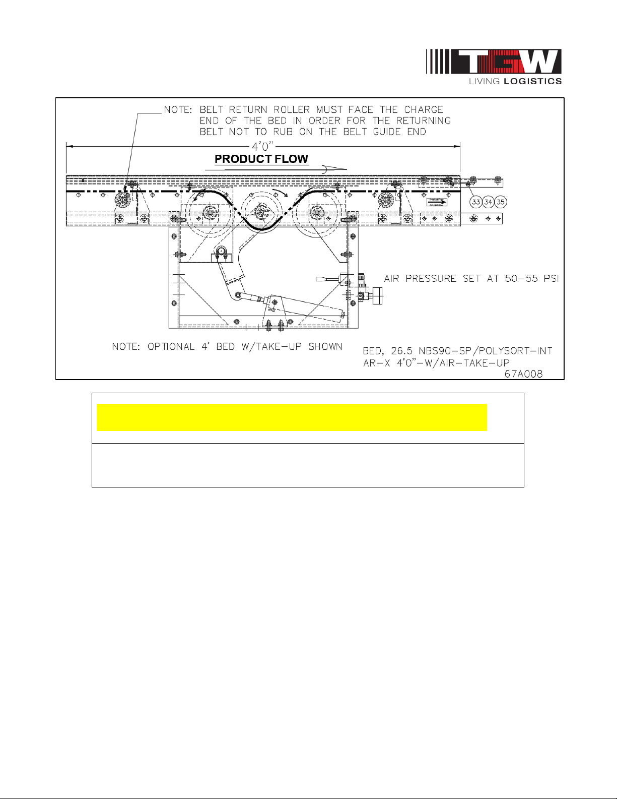
• Note: To avoid the belt rubbing/fraying on the guide ends the belt return roller must
face the charge end of the bed.
Page 43
NBS®90 PolySort & SP IOM
WARNING
8.9: NBS90 POLYSORT COMPONENT ORIENTATION
Using your conveyor system layout drawing and the numbers on the I.D. tags on each component,
position and orients the conveyor sections. You must know:
• The direction of product flow
• The elevation height
• The drive is positioned at the discharge end
• The end pulley is positioned at the charge end
• Ensure rails are aligned and snag free
IMPORTANT!
• Do not make alterations to the equipment without consulting with
user's representative and TGW Systems. Unauthorized
modifications to the equipment may impair its function, create a
hazardous condition, affect its useful life, and/or void the warranty.
P/N: 1193974 Revision Date: 4/25/2019 Page 43 of 83
Page 44
NBS®90 PolySort & SP IOM
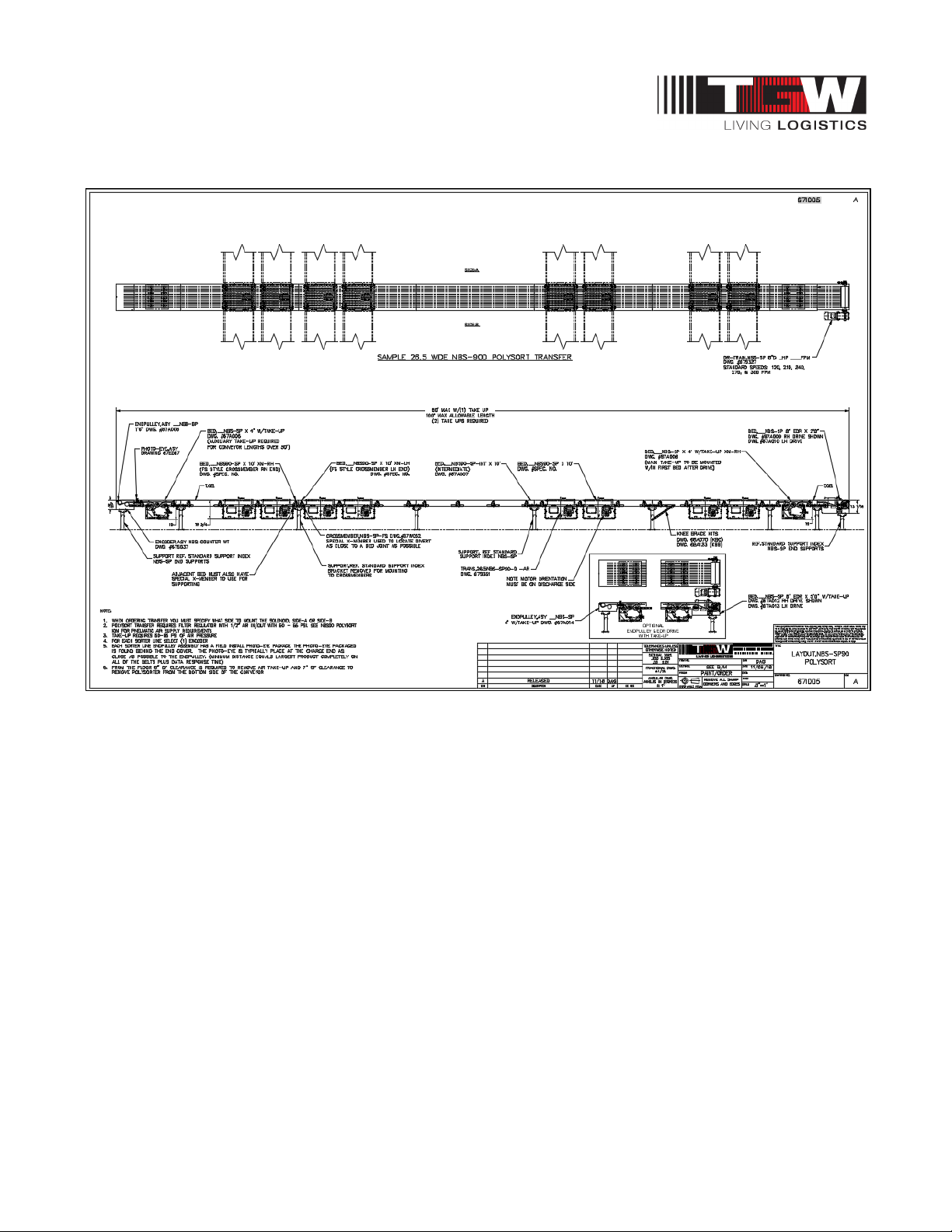
8.10: NBS90 POLYSORT TRANSFER GENERAL LAYOUT
General Layout, 26.5 Wide NBS-90D PolySort Transfer
P/N: 1193974 Revision Date: 4/25/2019 Page 44 of 83
Page 45
NBS®90 PolySort & SP IOM
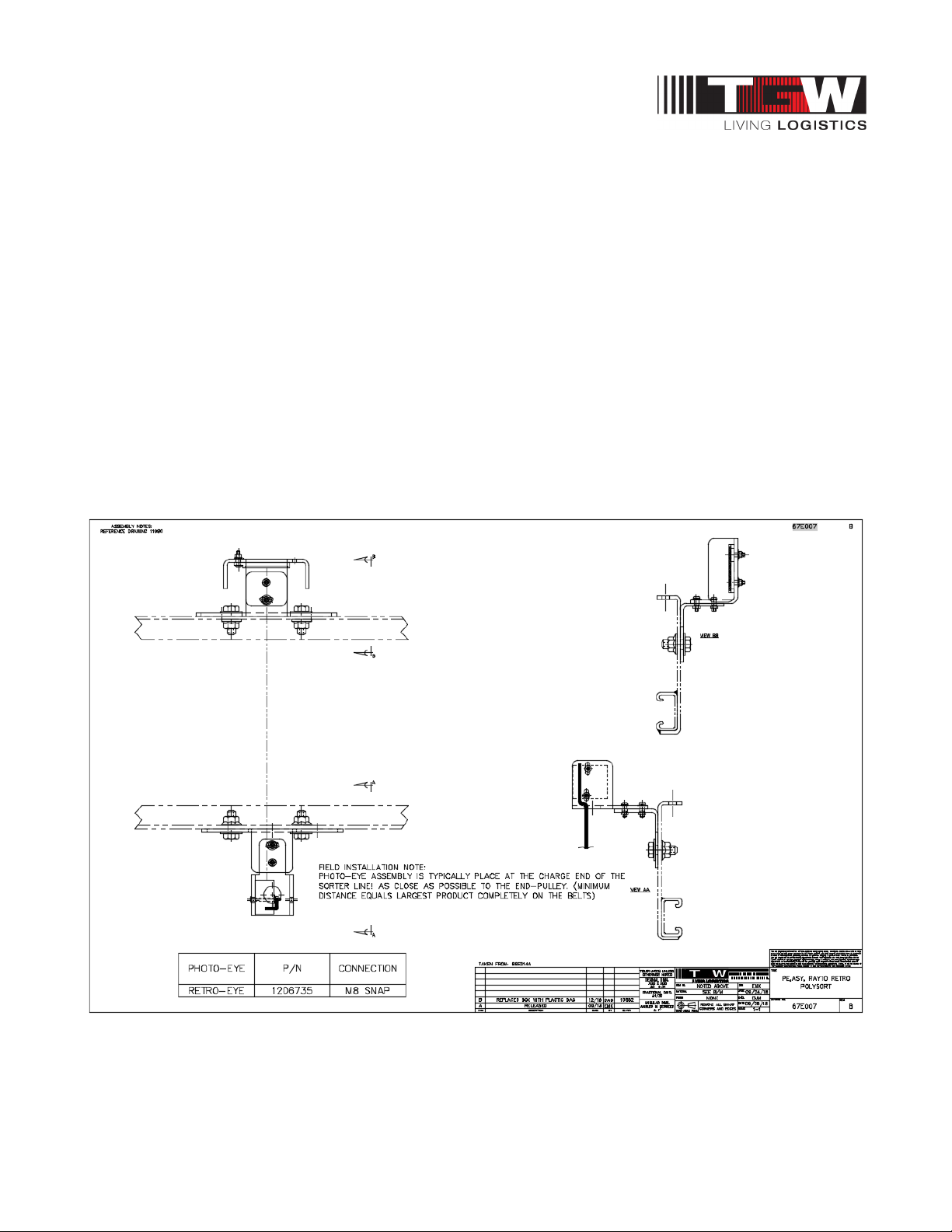
8.11: NBS90 POLYSORT SENSING SWITCHES
Retroreflective photoeye Ray 10
Adjust the retroreflective type as follows:
• Determine what sizes of target the photoeye must sense.
• Adjust for the worst case, usually smallest item, by loosening photoeye mounting nut and
aligning while making sure photoeye has unobstructed view of reflector.
• Move the target in and out of the field of detection to ensure that the photoeye energizes and
de-energizes.
Adjust the photoeye type as follows:
• Loosen photoeye switch mounting bolt and adjust photoeye so that the product passes
directly in front of the switch face, as close to the switch face as possible without making
contact.
• Check that the photoeye energizes and de-energizes as the product passes in front of the
eye’s face.
• Tighten the mounting bolt.
P/N: 1193974 Revision Date: 4/25/2019 Page 45 of 83
Page 46
NBS®90 PolySort & SP IOM
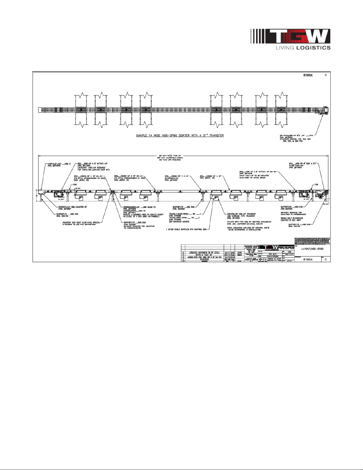
8.12: NBS90 SP SORTER TRANSFER GENERAL LAYOUT
General Layout, 14 Wide NBS-90D SP Transfer
P/N: 1193974 Revision Date: 4/25/2019 Page 46 of 83
Page 47
NBS®90 PolySort & SP IOM
CAUTION
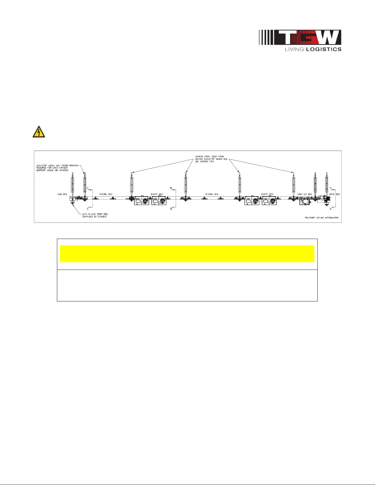
8.13: NBS90 POLYSORT CEILING SUPPORTED
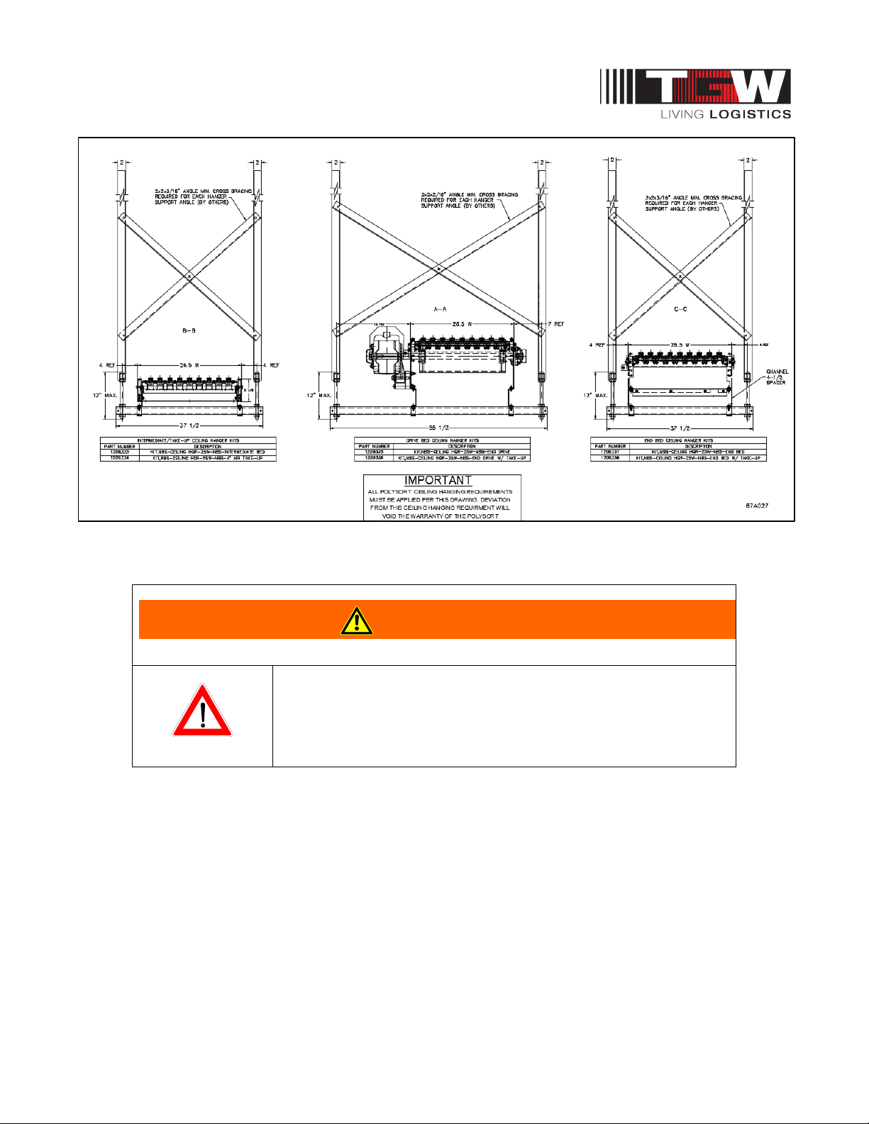
The NBS90 PolySort conveyor is designed to ALWAYS be supported at the bed joints. For ceiling
hanging applications, an NBS90 PolySort ceiling hanger kit MUST be used at the bed joints as shown
in the diagrams below. The end pulley and drive beds show connection locations for the specific ceiling
hanger kit designed for those locations. Along with the ceiling hangers, cross bracing is required for all
hangers. This ceiling hanging method provides the lateral conveyor rigidity.
Deviation from this ceiling hanging requirement will void the warranty of the NBS90 PolySort.
• Deviation from this ceiling hanging requirement will void the warranty of the NBS90
PolySort.
P/N: 1193974 Revision Date: 4/25/2019 Page 47 of 83
Page 48
NBS®90 PolySort & SP IOM
WARNING
Ceiling hanger diagrams are a guide to establish a final support design.
Consult structural engineer for actual application.
• Consult structural engineer for actual application.
P/N: 1193974 Revision Date: 4/25/2019 Page 48 of 83
Page 49
NBS®90 PolySort & SP IOM
8.14: NBS ALUMINUM EXTRUSION T-NUT CONNECTORS
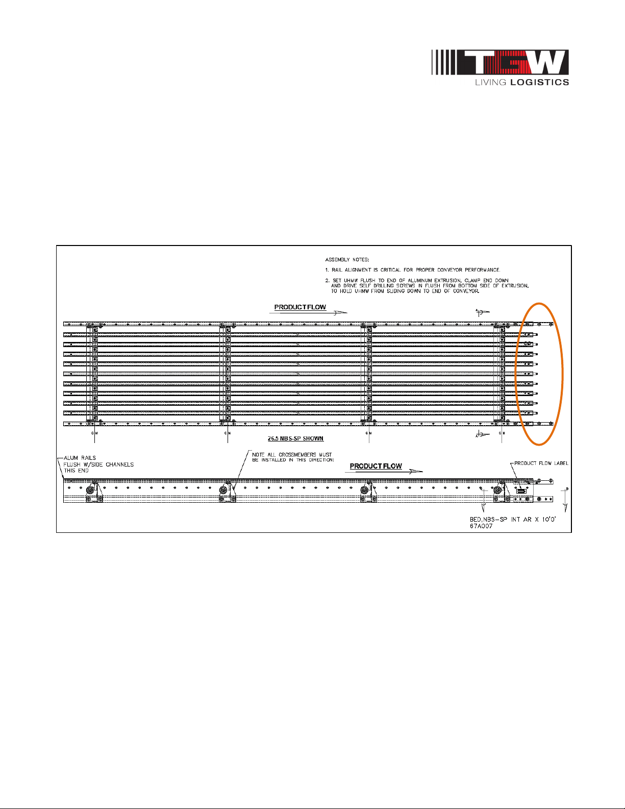
The aluminum extrusions that hold the UHMW belt guides are installed at the factory. The triple T-nut
connectors are mounted, at the factory, flush with the ends of the aluminum extrusions on the
discharge side of all NBS bed assemblies. These triple nut connectors should be extended half-way
out of the extrusions before "plugging in" the next bed downstream during installation. After all bed
components are installed, leveled and straightened the 5/16-18 hex head bolts used in the triple T-nut
connectors should all be loosened, to straighten the aluminum extrusion joints and re-tightened.
Note:
Ensure rails are aligned and snag free.
P/N: 1193974 Revision Date: 4/25/2019 Page 49 of 83
Page 50
NBS®90 PolySort & SP IOM
8.15: NBS BELT INSTALLATION
Pre-installation
Belts, as shipped from TGW Systems, are cut to length with lacing installed. Rolls of belting should be
stored on edge on a pallet. Never leave a belt where it may absorb moisture. Remove any tight
shipping banding immediately upon arrival. Lacing pins are taped inside the lacing on each belt.
The NBS90 PolySort conveyor should be completely installed and aligned before belt installation.
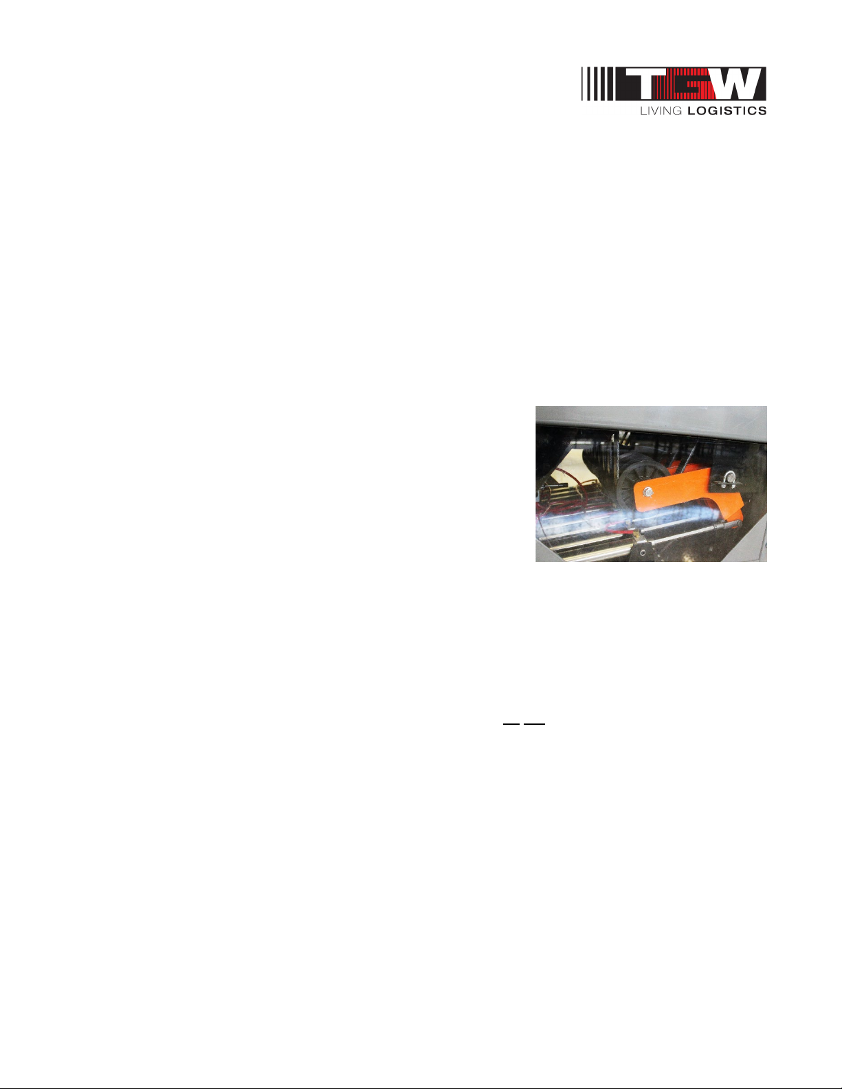
Remove the plexiglass side covers from the sides of the auxiliary belt take-up frame, exposing the takeup pulleys. Switch the take-up air switch to the un-tensioned position, raising the take-up pulleys to the
minimum take-up position.
Belt Threading
Because NBS uses multiple narrow belts of long length, it will be most efficient to have two people
working together during the threading process.
The belting must be uncoiled and laid out flat on the sorter, with
the smooth black carrying surface up. The belts must not be
allowed to twist along their length as they are installed. Start at the
charge end (farthest from the drive) and feed all of the belts
through together at the same time. Start the belts down between
the gap roller and the end pulley. Guide the belts under the 4"
diameter end pulley and up and over the 4" diameter snub pulley,
before passing through the belt guide wheels.
All belts must pass over any return rollers positioned to minimize
belt sag and through holes in crossmembers.
The black PVC surface of the belt should be up and the rough surface rides in the UHMW tracks.
Mesh the loops of the lacing on one end of the belt with the loops on the other, so the sides of the belt
are even, and install the lacing pin.
Belt Tracking
With the belts tensioned, "bump" the motor to be sure rotation is correct, the belts are running smoothly
and maintaining their position. Most NBS90 PolySort conveyors do not require belt tracking. However,
each conveyor should be checked at the charge and discharge ends to be sure the belts are floating in
a neutral position not crowding the sides of the UHMW guide tracks. If the belts are out of their grooves
or riding hard to one side fine adjustments can be made on the driven pulley jackscrew, at the
discharge end.
Reinstall the bottom pan on the end pulley assembly and access covers on the auxiliary belt take-up.
P/N: 1193974 Revision Date: 4/25/2019 Page 50 of 83
Page 51
NBS®90 PolySort & SP IOM
CAUTION
• As shown above: To avoid the belt rubbing/fraying on the guide ends the belt return
roller must face the charge end of the bed.
P/N: 1193974 Revision Date: 4/25/2019 Page 51 of 83
Page 52
NBS®90 PolySort & SP IOM
CAUTION
8.16: NBS BELT SPECIFICATIONS AND LACING
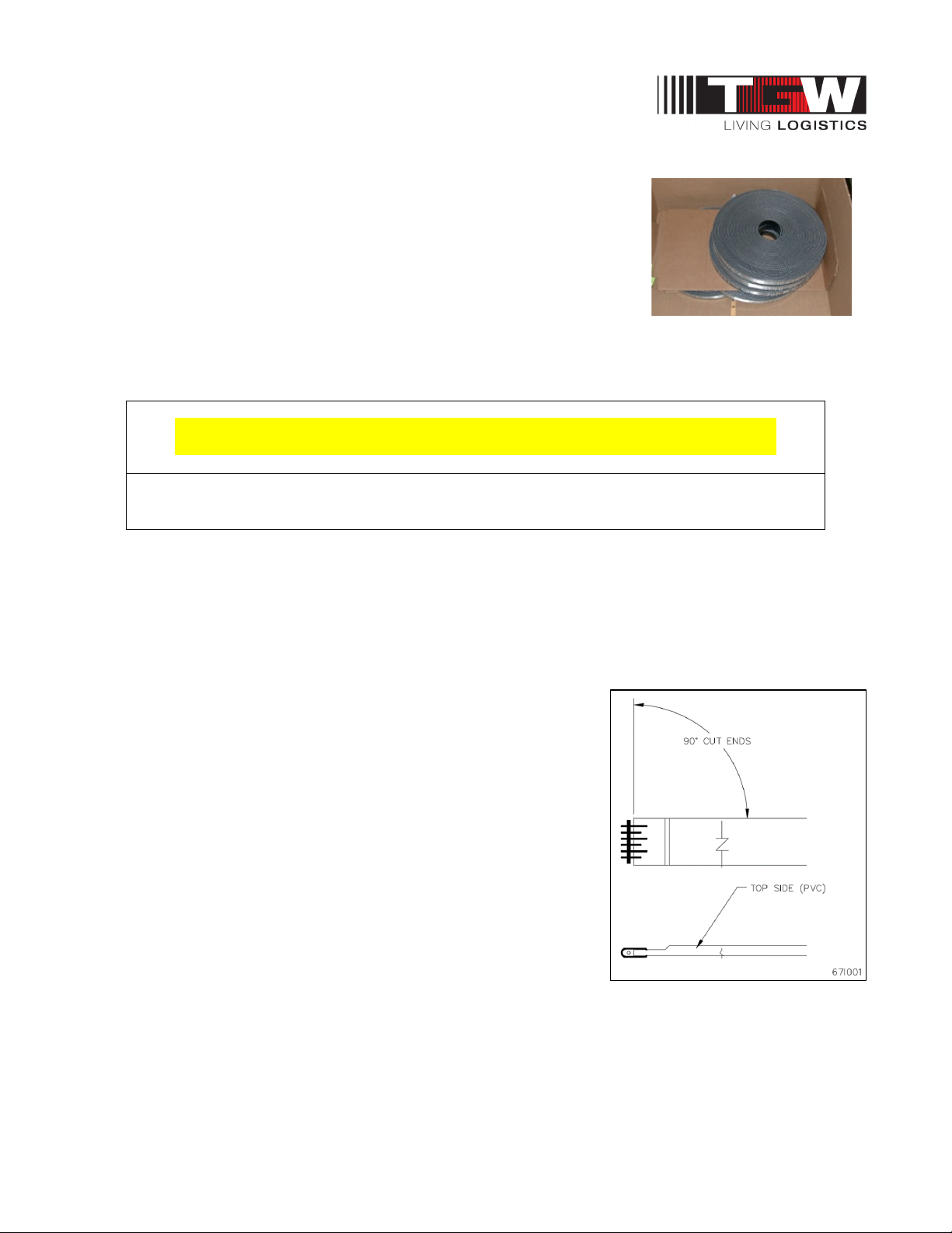
• PVC 200 belt
• Width: 15/16" + /- 1/32"
• Thickness: .203" +/- .015 thick, with a recessed
• Thickness at recess: .125" to .156"
• Lace: Clipper P/N 05265 U2S12 (tote); minimum number of
hooks = 5 on one end, 6 on other end.
• Lacing Pin: Nylostainless
• .093 dia. x 7/8” +/- 1/32” long (316 stainless steel w/nylon coating); clipper P/N 02670
• For field repair chamfer belt corners, no more than 1/8”.
• Only use the specified lacing and pin. Any substitution will result in premature belt failure.
8.16.1: NBS-90 PolySort Belt Replacement
Replacement belts may be ordered by the original "P/N" part number marked on the belt or belt length
can be determined by the following information.
• 2’-9’ drive bed = 5’ 11”-1/4” (71.25”)
• 5’0” Drive bed with take-up = 5’11-1/4” (71.25”)
• 1’6” End Pulley = 2’11”-3/8” (35.38”)
• 4’0” End Pulley with take-up = 8’3” (99”)
• NBS90 PolySort transfers require 0" each
• Take-up = 3-5/8” (3.625”)
• All other beds require 2 times their overall length.
NOMINAL WIDTHS (# OF BELTS)
• 26.5BF with 9 belts on 2 1/2” centers
8.16.2: NBS-90 SP Belt Replacement
Replacement belts may be ordered by the original "P/N" part
number marked on the belt or belt length can be determined by the
following information.
• 2’-9’ drive bed = 5’ 11”-1/4” (71.25”)
• 1’6” End Pulley = 2’11”-3/8” (35.38”)
• NBS90 SP transfers require 0" each
• Take-up = 3-5/8” (3.625”)
• All other beds require 2 times their overall length.
NOMINAL WIDTHS (# OF BELTS)
• 11.25 NBS SP = 3 belts
• 14 NBS SP = 4 belts
P/N: 1193974 Revision Date: 4/25/2019 Page 52 of 83
Page 53
NBS®90 PolySort & SP IOM
CAUTION
Chapter 9: NBS PNEUMATIC GENERAL GUIDELINES
General
Suggested requirements for NBS sorter and diverts
Every conveyor system is unique, with its own specific requirements. Therefore, the following is a
general guide.
MAIN FEEDER: Air velocity through the main feeder piping can be kept smooth with lower losses using
large diameter pipe with minimum bends and restrictions. Standard weight black pipe or copper is
suitable for plumbing the compressed air overhead to all points of use.
AIR DROPS: TGW Systems recommends using 3/4" pipe on air drops for high flow and low pressure
loss. The drop is terminated with a drain at the bottom. A tee located prior to the drain branches off to
the conveyor. This branch line must contain a lockout/shutoff. A shutoff must also be located in the drop
before the branch tee. OSHA Rule 29, CFR1910.147 requires energy sources (air drops) be turned off
and capable of being locked or labeled with a warning tag.
Note: NBS pneumatic systems does not require lubrication. Lubrication may affect the valving
operation and cause sluggish or erratic operation.
Important: If your air compressor uses synthetic oil, a coalescing filter plus a regular filter of 5 micron is
required. Synthetic oils will shrink the seals in pneumatic devices and valving.
• All air lines must be thoroughly blown out (of all debris) and the regulator must be set
as required before connecting air to the NBS.
P/N: 1193974 Revision Date: 4/25/2019 Page 53 of 83
Page 54
NBS®90 PolySort & SP IOM
CAUTION
CAUTION
9.1: NBS90 POLYSORT PNEUMATIC
Every conveyor system is unique, with its own specific requirements. Therefore, the following is a
general guide.
Main Feeder
Air velocity through the main feeder piping can be kept smooth with lower losses using large diameter
pipe with minimum bends and restrictions. Standard weight black pipe or copper is suitable for
plumbing the compressed air overhead to all points of use.
Air Drops (NBS90 PolySort)
TGW Systems recommends using 3/4" pipe on air drops for high flow and low pressure loss. The drop
is terminated with a drain at the bottom. A tee located prior to the drain branches off to the conveyor.
This branch line must contain a lockout/shutoff. A shutoff must also be located in the drop before the
branch tee. OSHA Rule 29, CFR1910.147 requires energy sources (air drops) be turned off and
capable of being locked or labeled with a warning tag.
NOTE: The NBS90 PolySort and SP pneumatic system does not require lubrication. Lubrication may
affect valve action and cause sluggish or erratic operation.
IMPORTANT! If your air compressor uses synthetic oil, a coalescing filter plus a regular filter of 5
micron is required. Synthetic oils will shrink the seals in pneumatic devices and valves.
• All airlines must be thoroughly blown out (of all debris) and the regulator must be set as
required before connecting air to the NBS.
• NBS90 PolySort diverters must not be operated above 55 PSI. Exceeding this may
damage unit.
P/N: 1193974 Revision Date: 4/25/2019 Page 54 of 83
Page 55

NBS®90 PolySort & SP IOM
9.2: NBS90 POLYSORT AIR SUPPLY REQUIREMENTS
Pneumatic pressure requirements:
• Maximum conveyor length each way from regulator is 80'.
• Locate regulator in center of conveyor, if possible, for maximum efficiency.
• Overhead feeder line pressure to be 100 PSI minimum.
• Low pressure switch should be set at 10 PSI below the operating air pressure for the specific
device noted below.
• In high humidity or low temperature, use air dryer.
• Use 5 micron filter.
• Lockout/shutoff valve to be provided by air system installer.
Regulators pressure set to unit requirements:
• Air take-up 50-55 PSI
• 90º PolySort transfer 50-55 PSI
NBS90 PolySort Diverters are actuated by four air bags.
The air consumption per divert is calculated by:
• .072CF (cubic feet) X CPM (cycles per min.) = SCFM (Standard Cubic Feet / Minute)
P/N: 1193974 Revision Date: 4/25/2019 Page 55 of 83
Page 56
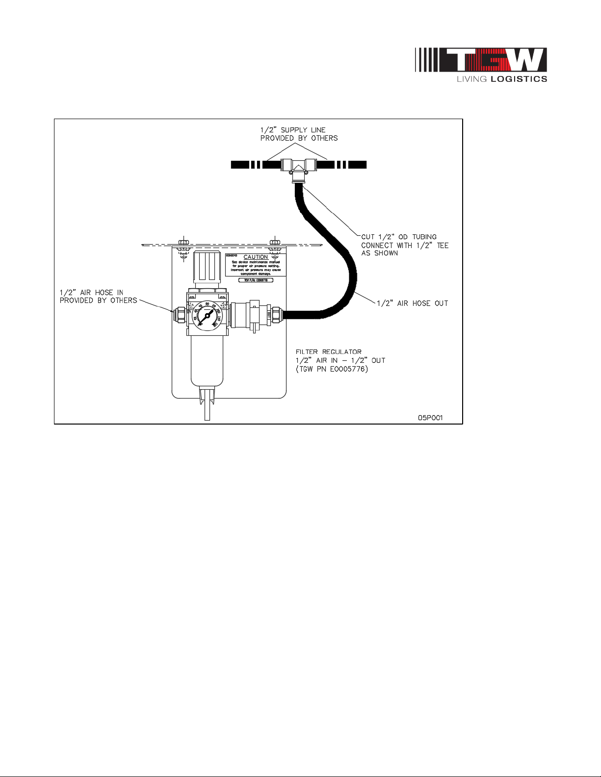
NBS®90 PolySort & SP IOM
9.3: NBS90 SP AIR SUPPLY REQUIREMENTS
NBS90 SP PNEUMATIC REQUIREMENTS
• Maximum conveyor length each way from regulator is 80'. Locate regulator in center of
conveyor, if possible, for maximum efficiency.
• Overhead feeder line pressure to be 100 PSI minimum
• Low pressure switch to be set at 90 PSI
• In high humidity or low temperature, use air dryer
• Use 5 micron filter
• Lockout/shutoff valve to be provided by air system installer
• Regulators pressure set to unit requirements:
NBS90 SP
• Air take-up 50-55 PSI
• 90º transfer 45-50 PSI
NBS90 SP Formulas
NBS 90SP transfers are actuated by a single air cylinder with a 2" bore and 1/2" stroke.
The air consumption per transfer is calculated by:
• .0092CF (cubic feet) X CPM (cycles per min.) = SCFM (Standard Cubic Feet / Minute)
Adding together the air requirements of all transfers connected to one regulator will give total air flow
requirements for that NBS air system.
P/N: 1193974 Revision Date: 4/25/2019 Page 56 of 83
Page 57
NBS®90 PolySort & SP IOM
CAUTION
9.4: NBS90 SP & POLYSORT AIR LINE CONNECTIONS
Source Air Connection
Select the best position along the conveyor to connect the source air from a drop line. Ideally, the
regulator should be centrally located along the sorter and should not be more than 80' from the furthest
diverter/transfer or drive.
Attach the filter/regulator assembly to the bottom flange of the side frame using the mounting bracket
supplied with the kit.
The source airline that distributes air to the diverters/transfers should be 1/2" hose that is rated to
handle a pulsating 60psi line pressure. TGW Systems part number 89000572 TUBING, URETHANE
1/2 OD is available for this purpose.
Cut into the supply line along the sorter bed and install the source airline tee fitting TGW Systems part
number 89000640. Connect the source air line between this fitting and the filter/regulator output.
The hose size at each diverter/transfer is 3/8 OD and the source airline can be tapped at each location
using TGW Systems part number 89000640 1/2” tee and 1/2” x 3/8” tube reducer fitting TGW Systems
part number 1155149.
Low Pressure Air Switch
The installation of an air pressure switch in the NBS air supply circuit, to detect a drop in air pressure
below required levels, is recommended. If pressure drops below approximately 40 PSI, the conveyor
system should shut off.
It is recommended that this air switch be located either at the furthest end of the source air line away
from the regulator or at the pneumatic belt take-up located in or near the drive bed at the discharge end
of the sorter.
• Do not use a lubricator. When replacing filter/regulator bowl, lightly lubricate seal with
mineral oil. Do not use synthetic oils such as esters or silicones. DO NOT get oil inside
filter/regulator bowl.
• The function of the low pressure air switch is to protect the drive pulley and the NBS
narrow belts from being damaged from slipping under load in the event of an air
pressure disruption. Loss of air pressure may also cause diverter / transfer jams.
P/N: 1193974 Revision Date: 4/25/2019 Page 57 of 83
Page 58

NBS®90 PolySort & SP IOM
9.5: NBS90 SP SOLENOIDS
For the sake of simplicity, only two different solenoids are used to actuate the NBS90-SP transfers,
120VAC or 24VDC.
Both models use spring return, 4-way solenoids with a DIN electrical connector, mounted on the
outside, opposite the discharge direction of the diverter/transfer.
The lift mechanism of the NBS90-SP is powered in both directions and has combination needle-valve /
exhaust mufflers installed in ports "EA" & "EB" that are used to adjust actuation speeds.
Solenoids are plumbed such that the diverter/transfer is normally in the down position and raises on
solenoid activation.
The TGW Systems part numbers for replacement solenoids are:
• E0002998 VALVE, SMC 4-WAY 24VDC DIN CONN
• E0002995 VALVE, SMC 4-WAY 110VAC DIN CONN
P/N: 1193974 Revision Date: 4/25/2019 Page 58 of 83
Page 59
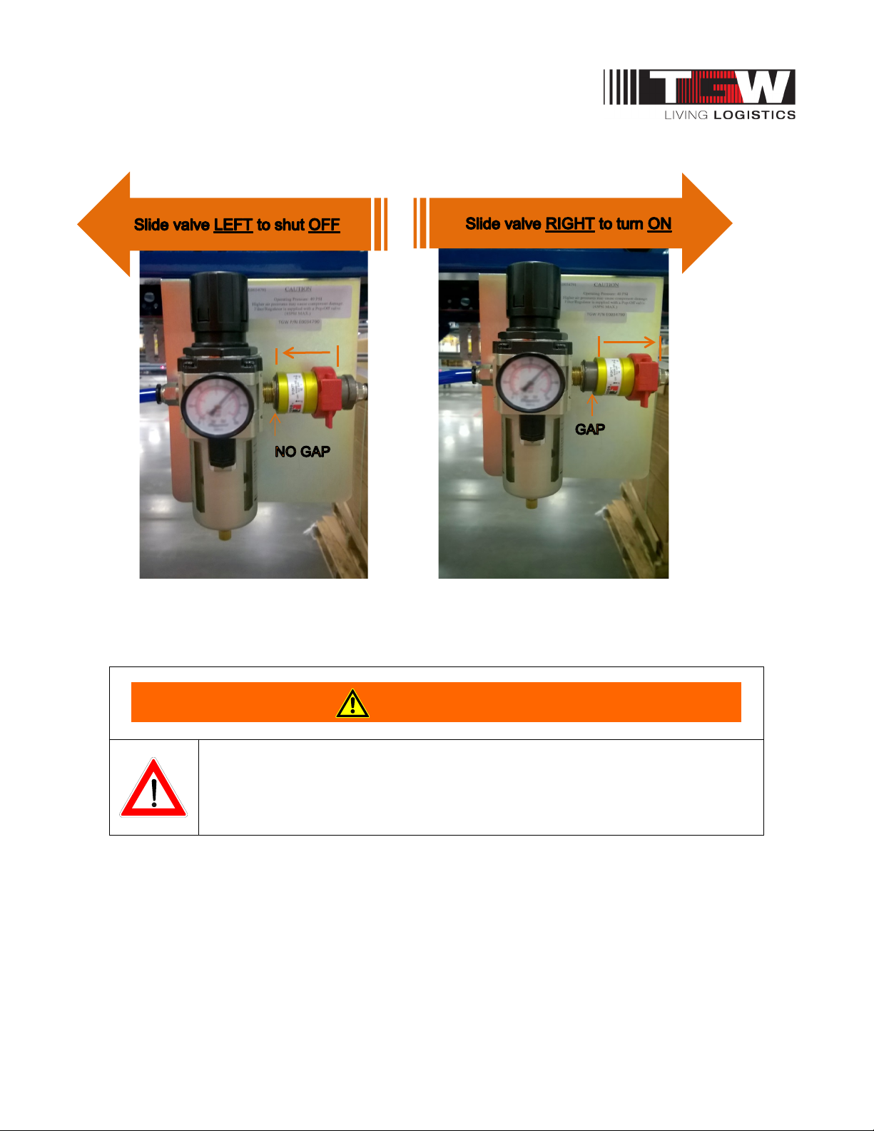
NBS®90 PolySort & SP IOM
WARNING
9.6: NBS AIR REGULATOR LOCK OUT VALVE ON AND OFF POSITION
Note:
The air regulator valve label details the on and off positions.
For air pressure regulations please see detailed instruction in this manual.
• Do not remove and install sleeve valve to infeed side of regulator. Back
feeding through the regulator will cause damage and void the warranty.
P/N: 1193974 Revision Date: 4/25/2019 Page 59 of 83
Page 60

NBS®90 PolySort & SP IOM
9.7: NBS COMMISSIONING OF EQUIPMENT
General
Commissioning of the equipment can best be defined as the final adjustments and test of the installed
equipment required for its proper operation. The need for commissioning is inherent, since the
individual components of equipment are brought together at the installation site to operate as a system.
Mechanical and electrical commissioning are most often carried out simultaneously. Commissioning
must simulate the actual operation of the system as closely as possible to demonstrate the ability to
perform reliably at the specified rate in the prescribed operational sequence.
During the Commissioning Phase, it is necessary to load the equipment with product to be conveyed,
which provides the means of detecting those areas requiring adjustment. Personnel will be required to
support operational functions. This may serve as part of operator training and familiarity with the
system. During the commissioning activity, special attention should be directed toward personnel
safety. No unnecessary risks should be taken that would endanger the safety of any personnel. All
personnel must familiarize themselves with all safety features of the system such as emergency stops
and motor disconnects.
Mechanical Static Checkout
(No power to the conveyor.)
• The belt tension and air pressure must be set to the correct pressure setting, which is
dependent on sorter width. Air pressure higher than required can cause belt failure.
• Listen for air leaks after air pressure is turned on.
• Check the plumbing of the solenoids.
• Follow the belt path through the entire conveyor. The belt must be threaded through the
drive per the diagram in the Belt Installation section, all of the belts must be captured
between the grooved guide pulleys at each diverter location, and no belt should be threaded
under a crossmember (belt path labels are attached at each diverter location from the
factory).
• Visually inspect the installation. Is the conveyor straight? Is the conveyor reasonably level
from side to side? From end-to-end?
• Check guard rail clearance to product.
• Eliminate all catch points.
• Check conveyor elevations.
• All bolts and set screws tight.
• Check product clearance to overhead structures.
• Simulate all operational functions with actual product.
• All guards in place with proper clearance.
• All OSHA required guards in place on walkways, catwalks, ladder-ways, floor openings, etc.
• All labels and warning signs in proper place, unobstructed.
P/N: 1193974 Revision Date: 4/25/2019 Page 60 of 83
Page 61
NBS®90 PolySort & SP IOM
WARNING
Mechanical Dynamic Checkout
(Power to the conveyor, but no product on it.)
• Turn the motor on. With the belt moving make sure each belt has proper tension.
• Actuate each diverter solenoid manually.
• Check the belt tracking.
• NBS90 Transfer motors must be controlled to
run on demand
P/N: 1193974 Revision Date: 4/25/2019 Page 61 of 83
Page 62
NBS®90 PolySort & SP IOM
WARNING
Chapter 10: NBS MAINTENANCE & TROUBLESHOOTING
General
The key to ensuring the expected return on investment is to protect against premature failure with a
well-planned program of preventive maintenance.
Preventive maintenance programs examine what may fail and then formulate action plans which will
prevent failure or downtime. This kind of maintenance includes lubrication and replacement or repair of
parts before failure but after expected life has been attained.
Preventive maintenance will save expensive downtime and wasted energy. It will increase the life of
components. Along with preventive maintenance, there should be a record-keeping system. You must
know what problems you have had in the past and when different components were serviced.
A visual and audible inspection should be taken every day. You can see if a chain is loose, oil leaking,
sprocket worn; or you can hear a faulty bearing, noisy chain or any other noise that might indicate a
problem. When something major goes wrong with some component, records should be kept to see if a
pattern to the problem occurs.
All personnel working in close proximity to the conveyor should inform maintenance or their supervisor
of any unusual noise.
• Do not perform maintenance on the conveyor until the startup
controls are locked out and cannot be turned on by any
person other than the one performing the maintenance. If
more than, one member of a crew is working on the
Gearmotor
The drive unit should be checked monthly. Check the gearmotor for leaking seals. Check the gearcase
for proper oil level and add the approved oil for your particular unit. Check for overheating, vibrations
and dirt buildup.
conveyor, EACH CREW MEMBER MUST HAVE A LOCK
ON THE POWER LOCK OUT. The air pressure must be
turned off to the work area. All pneumatic devices must be
de-energized to prevent accidental cycling of the device.
• Make sure personnel are clear of all conveyor equipment
before restarting the system.
Each Nord gearmotor is supplied from the factory with the correct grade and quantity of lubricant for the
specified mounting position. Under special circumstances such as high or low ambient temperatures,
optional oils should be used.
P/N: 1193974 Revision Date: 4/25/2019 Page 62 of 83
Page 63
NBS®90 PolySort & SP IOM
WARNING
WARNING
Rollers
All rollers used in NBS equipment have precision, sealed lubed for life bearings and do not require
maintenance. Periodically removing the rollers has an added benefit of distributing the wear on the
bearing inner race by rotating the axle to a new position. If a defective roller bearing is found, replace
the roller.
Do not allow tape, banding, shrink wrap, etc. to build up on roller or pulleys. This can cause rollers to
jam and the belt to mistrack. If this is a common occurrence due to the product packaging, clean up on
a regular schedule.
• Use a blunt object to remove rollers from frame like a putty
knife and a screwdriver. Using sharp pointed object could slip
and cause injury.
Air System
The best preventive maintenance for any air operated device is clean air. Always be alert for air leaks
anywhere in the system and correct promptly. Check all air line filter bowls weekly for accumulated
water and drain if necessary. Check for proper PSI settings on air regulators.
• Check to confirm tools and foreign objects have not been left
on or inside the conveyor.
• Check to confirm all loosened parts have been retightened.
• Check to confirm all guards have been installed.
• Prohibit riding on conveyor by anyone.
• Think before making any adjustments. It may prevent an
injury. Remember, all moving components are potentially
dangerous.
• Protect yourself from unexpected starts when working on a
stopped unit by locking and tagging the control panel or
disconnect switch that supplies power to the unit.
P/N: 1193974 Revision Date: 4/25/2019 Page 63 of 83
Page 64
NBS®90 PolySort & SP IOM
WARNING
WARNING
Motor Controls
Inspection (Semi-Yearly)
• Before servicing or performing any work in the motor control
panel, disconnect and lockout the main incoming service. If
Excessive overheating is indicated by discoloration of components. Most often, these symptoms are a
sign of loose connections. If left uncorrected this can eventually cause arcing between components,
leading to destruction of the controls. It is normal to find the interior of the control cabinet very warm
when it is first opened.
only the panel disconnect is off, the incoming side will still be
hot.
The condition of contacts must be checked on all contactors and starters that show signs of
overheating. Make sure that they are free of dust and are not excessively pitted or burned. When
badly burned or worn, the contacts must be replaced.
In the course of inspecting contact condition, spring pressure should be checked. As contact surface
wears down, spring pressure can be lost because of the overheating. Contact spring resiliency can
usually be detected by fingertip pressure.
Check for faulty door gaskets especially when there are excessive deposits of foreign materials.
Particular attention should be given to conductive deposits because they can cause flashovers and
premature component failure when allowed to collect to any great extent. Either reposition or replace
defective gaskets and clean the control cabinet.
• Avoid touching components until they have had time to cool.
Some may still be hot.
Check all overload settings on motor controls. Check for loose wiring and tighten as required.
Cleaning
When cleaning a control cabinet, it is best to use a vacuum cleaner rather than compressed air. A
vacuum cleaner removes rather than redistributes dust and dirt. Compressed air can damage and
displace relay contacts and springs.
P/N: 1193974 Revision Date: 4/25/2019 Page 64 of 83
Page 65

NBS®90 PolySort & SP IOM
10.1: NBS MAINTENANCE CHECKLIST
End Pulley Assembly
• Examine end pulley assembly. Remove any residue clinging to end pulley, and end pulley
snubber.
• Check to see if belt is tracked correctly thru lower belt guide wheels. Examine guide wheels
for wear. Replace any wheels that are excessively worn.
• Remove any residue or buildup of fibers between UHMW rails at joints.
Intermediate Bed Assembly
• Remove any residue or buildup of fibers between UHMW rails joints.
• Remove any residue or build up on carrier rollers.
Drive Assembly
• Examine drive pulley for excessive lagging wear.
• Remove any residue built up on drive pulley.
• Check to see if belt is tracked correctly thru lower belt guide wheels. Examine guide wheels
for wear. Replace any wheels that are excessively worn.
• Examine the belt guide feeder rollers. Remove any residue built up on rollers.
• Examine individual take up wheels for wear. Clean off any build up on wheels.
• Examine take up snubber pulleys. Clean off any residue built up on pulleys.
• Check chain tension. An over tensioned chain will cause excessive gearbox noise
Transfer Module
• Remove any residue or build up on transfer rollers.
• Check tension of both timing belts. (Drive and jump belts)
• Check height of transfer rollers above the belt top surface. Check the plane passing over
the transfer rollers for level and parallelism to belt surfaces. Replace any missing hardware,
and tighten any loose hardware.
Encoder
• Remove any residue or buildup on encoder wheels.
P/N: 1193974 Revision Date: 4/25/2019 Page 65 of 83
Page 66
NBS®90 PolySort & SP IOM
WARNING
10.2: MAINTENANCE SCHEDULE
Periodic maintenance intervals shown may vary with load, speed, hours of daily operation, ambient
temperature, humidity, etc. Intervals can be established by fairly frequent maintenance at first, then
lengthen the intervals as justified by observation of need based on history. The following is based on 5
days per week, 8 hours per day under normal conditions.
Daily
• Listen to everything for unusual noises or vibration.
• Visually inspect to see that conveyor sections are clear and free of debris.
• Check to see that all safety guards are in place.
• Check any oil leakage.
• Check any unusual noises or vibration.
• Check for loose bolts or parts.
• Check air filter bowls for accumulated water.
• Listen for air leaks.
Weekly
• Inspect bearings, gear reducers and motors for excessive noise or heat.
• Clean breather cap on gear motor (if used).
• Check operation of all electrical controls.
• Inspect motor mounting bolts.
• Check for proper PSI on air regulators.
• Prohibit riding on conveyor by anyone.
• Think before making any adjustments. It may prevent an
injury. Remember, all moving components are potentially
dangerous.
• Protect yourself from unexpected starts when working on a
stopped unit by locking and tagging the control panel or
disconnect switch that supplies power to the unit.
P/N: 1193974 Revision Date: 4/25/2019 Page 66 of 83
Page 67
NBS®90 PolySort & SP IOM
WARNING
Monthly
• Check air filters for cleanliness.
• Clean chains and sprockets and lubricate with SAE 30 weight oil or equivalent. (Check
chain tension and tightness of all adjusting screws.)
• Check drive unit for leaking seals and oil level in gearcase (if applicable), unusual noises,
vibration and stress cracks.
Semi-Yearly
• If dry sounding, lubricate unsealed bearings in rollers with light oil. Check free spin of
rollers.
• Drain and flush gearcase after each 2,500 hours of normal operation or at least every 6
months (if applicable).
• Grease motor shaft bearings.
• Inspect and clean motor control centers.
• Grease regreasable bearings.
Yearly
• Change oil in gearboxes.
• Inspect tightness of all nuts and bolts on units. Readjust and, if necessary, retighten.
• Check for plumb and level. Shims have been known to vibrate out from under supports in
isolated incidents.
• Touch up paint that has been chipped. Unpainted surfaces will rust.
• Inspect for stress/fatigue cracks in frame and supports.
• Check to confirm tools and foreign objects have not been left
on or inside the conveyor.
• Check to confirm all loosened parts have been retightened.
• Check to confirm all guards have been installed.
P/N: 1193974 Revision Date: 4/25/2019 Page 67 of 83
Page 68

NBS®90 PolySort & SP IOM
Problem
Possible Cause
Remedy
straight
proper height
to ensure data is correct.
accordingly.
water is present
10.3: NBS TROUBLESHOOTING GUIDE
1. Belts rolling out of
guide tracks
2. Divert Tub engaging
at wrong time
Conveyor not installed
Conveyor not installed level Inspect conveyor to insure there are
Air pressure for the belt takeup is set too low
Divert is not rising up to
Divert is not rising up to
proper height
Divert spur isn’t set to the
proper height
PLC programming Inspect timing of logic with encoder
Straighten conveyor
not low/high spots at the divert
points. Re-level conveyor as
necessary
Set air pressure to the proper PSI.
Reference IOM manual
Verify air pressure setting.
Verify the number of diverts per air
drop. Consult IOM Manual to verify
that number of diverts per air drop
does not exceed TGW
recommendations.
Inspect and adjust height of divert
spur as needed.
Solenoid wired incorrectly Inspect wiring, and adjust
Clogged solenoid Inspect solenoid valve to ensure no
3. Belt Failure Routing of belt Inspect belt routing to ensure proper
installation. Refer to IOM Manual for
additional information.
Belting rails not aligned
properly
Incorrect belt tension Inspect air pressure within belt take-
P/N: 1193974 Revision Date: 4/25/2019 Page 68 of 83
Check rail alignment at joints to
ensure proper alignment.
up to ensure proper setting
Page 69

NBS®90 PolySort & SP IOM
Problem
Possible Cause
Remedy
not correct
adjust accordingly.
the rail.
4. Product not diverting
correctly
Discharge conveyor unit not
in proper location
Based upon product being handled
on NBS discharge conveyor
location is variable; refer to IOM
Manual for further assistance.
Height of discharge conveyor
Inspect discharge conveyor, and
5. Loud humming noise Belts installed incorrectly Inspect belt installing to ensure
proper side is making contact with
P/N: 1193974 Revision Date: 4/25/2019 Page 69 of 83
Page 70
NBS®90 PolySort & SP IOM
WARNING
10.4: NBS REPAIR PROCEDURES
Gearmotors
NBS drive units use Gearmotors which are properly filled at the factory with sufficient lubrication for
more details contact the specified gearmotor manufacture details.
Disassembly/assembly procedure as follows:
• Remove necessary guards to access maintenance areas.
• Disconnect any electrical connection.
• Remove Gearmotor.
• Perform required maintenance.
• Reverse procedures for assembly.
• After all fasteners are tight, double check chain tension and sprocket alignment.
• Replace all guards.
Solenoid Valves
In order to minimize downtime, it is normally not feasible to repair malfunctioning electrical or valve
components while leaving the conveyor unusable. Spare components should be kept in stock for
emergency replacement. If feasible, the part may be repaired later to replace maintenance stock. Items
which cannot be readily repaired or are questionable should be replaced. Components under warranty
should not be repaired except in an emergency.
• Before removing a valve or other pneumatic component, shut
off and exhaust the entire pneumatic circuit and shut off and
lockout electrical supply.
P/N: 1193974 Revision Date: 4/25/2019 Page 70 of 83
Page 71

NBS®90 PolySort & SP IOM
Chapter 11: PARTS IDENTIFICATION
11.1: REPLACEMENT PARTS IDENTIFICATION
This section is used to identify parts that may require replacement during the life of the conveyor. Parts
which specifically pertain to TGW conveyor are included with illustrations.
A "Recommended Spare Parts List" is published for all conveyor orders of $20,000 or more. This spare
parts list is sent to the purchaser approximately (2) weeks after the order is received. It includes part
numbers, description, pricing and recommended quantities to be kept on hand for maintenance.
If you are unable to locate this document, another may be obtained by contacting the TGW Lifetime
Services at 231-798-4547.
11.2: SPARE PARTS PRIORITY LEVEL EXPLANATIONS
Level #1
Failure of a priority level #1 spare part (“A” level part) may cause major disruption of system
performance.
Priority level 1 spare parts must be on-hand, and available to be replaced in the event of a component
failure that could shut down a critical function of a conveyor system.
Priority level 1 spare parts include motors, gear reducers, gearmotor, motorized rollers, air solenoid
valves, and related components. The majorities of these parts are purchased from TGW Systems
vendors and carry their own warranties through these vendors. For more warranty information, see
TGW Systems Equipment Warranty.
Level #2
Failure of a priority level #2 spare parts (“B” level part) usually is gradual and should not cause
a major system disruption.
Priority level 2 spare parts are parts required for smooth system operation and preventative or regular
mechanical maintenance.
Priority level 2 spare parts include roller chain, sprockets, belt pulleys, rollers, air cylinders, and other
related parts whose failure should not stop a conveyor system suddenly. These parts tend to wear out
gradually and are not know to fail suddenly.
Level #3
Priority level #3 parts (“C” level part) rarely fails and are easily obtainable.
Priority level 3 spare parts are parts that rarely fail or maybe optionally used by the customer.
P/N: 1193974 Revision Date: 4/25/2019 Page 71 of 83
Page 72
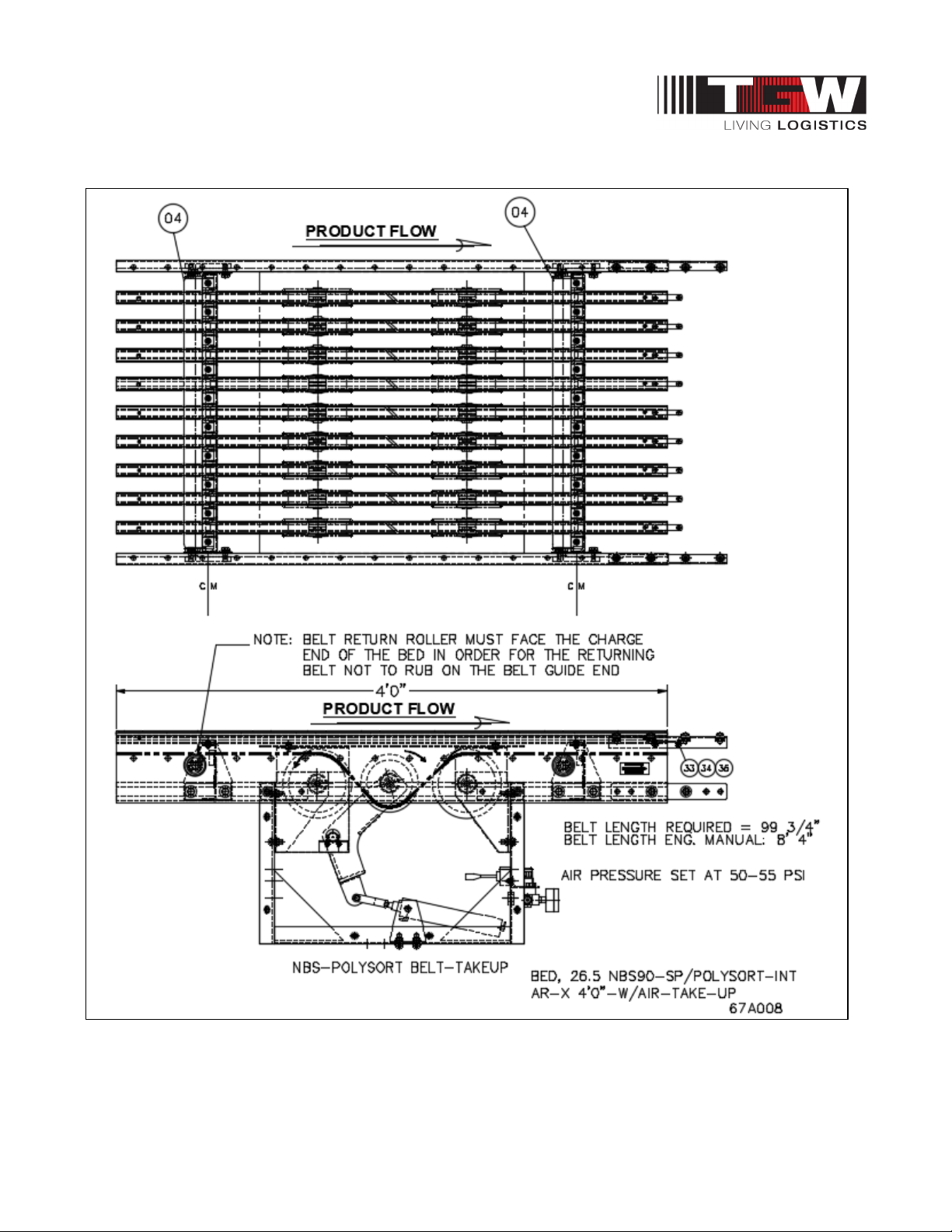
NBS®90 PolySort & SP IOM
11.3: NBS90 POLYSORT INTERMEDIATE BED AR W/AIR TAKE-UP 4’0”
P/N: 1193974 Revision Date: 4/25/2019 Page 72 of 83
Page 73
NBS®90 PolySort & SP IOM
Balloon Description Width & Item #
4 ROLLER,RET 26.5NBS-SP 1.9PRBG 1202217
Ref Dwg. 67A008
NBS90 PolySort Intermediate Bed AR 4'0" W/Air Take-up
BED,NBS SP-26.5W-TAKEUP-AR-4'0"-AIR OP
11.3.1: Replacement Parts – NBS90 PolySort Intermediate Bed AR W/Air Take-up 4’0”
P/N: 1193974 Revision Date: 4/25/2019 Page 73 of 83
Page 74
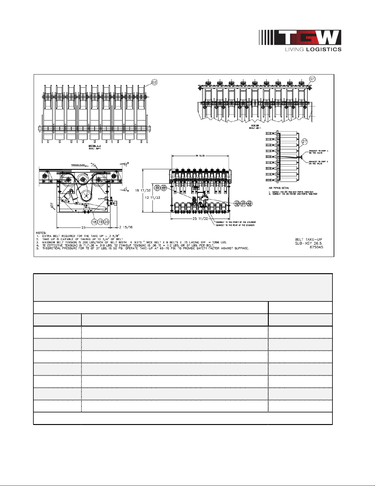
NBS®90 PolySort & SP IOM
Balloon Description Width & Ite m #
1 WHEEL,ASY NBS-SP TAKE-UP 6"OD E0002784
2 WHEEL,ASY NBS-SP TAKE-UP 5"OD E0002785
18 CYL,BIMBA BFT-176-DNR E0002793
25/01 REGULATOR,1/4"NPT PORTS E0002964
25/02 GAUGE,SCHRADER P781642 89000133
25/07 VALVE, 4 WAY HAND LEVER E0002795
27 TUBING,1/4"POLYU-95DURO.160ID E0001391
NBS90 PolySort Belt Take-up
ENDPULLEY,NBS SP-26.5W-AR-4'0"-W /AIR TAKEUP
REF DWG# 67S045
11.4: NBS90 POLYSORT BELT TAKE-UP
11.4.1: Replacement Parts – NBS90 PolySort Belt Take-up
P/N: 1193974 Revision Date: 4/25/2019 Page 74 of 83
Page 75
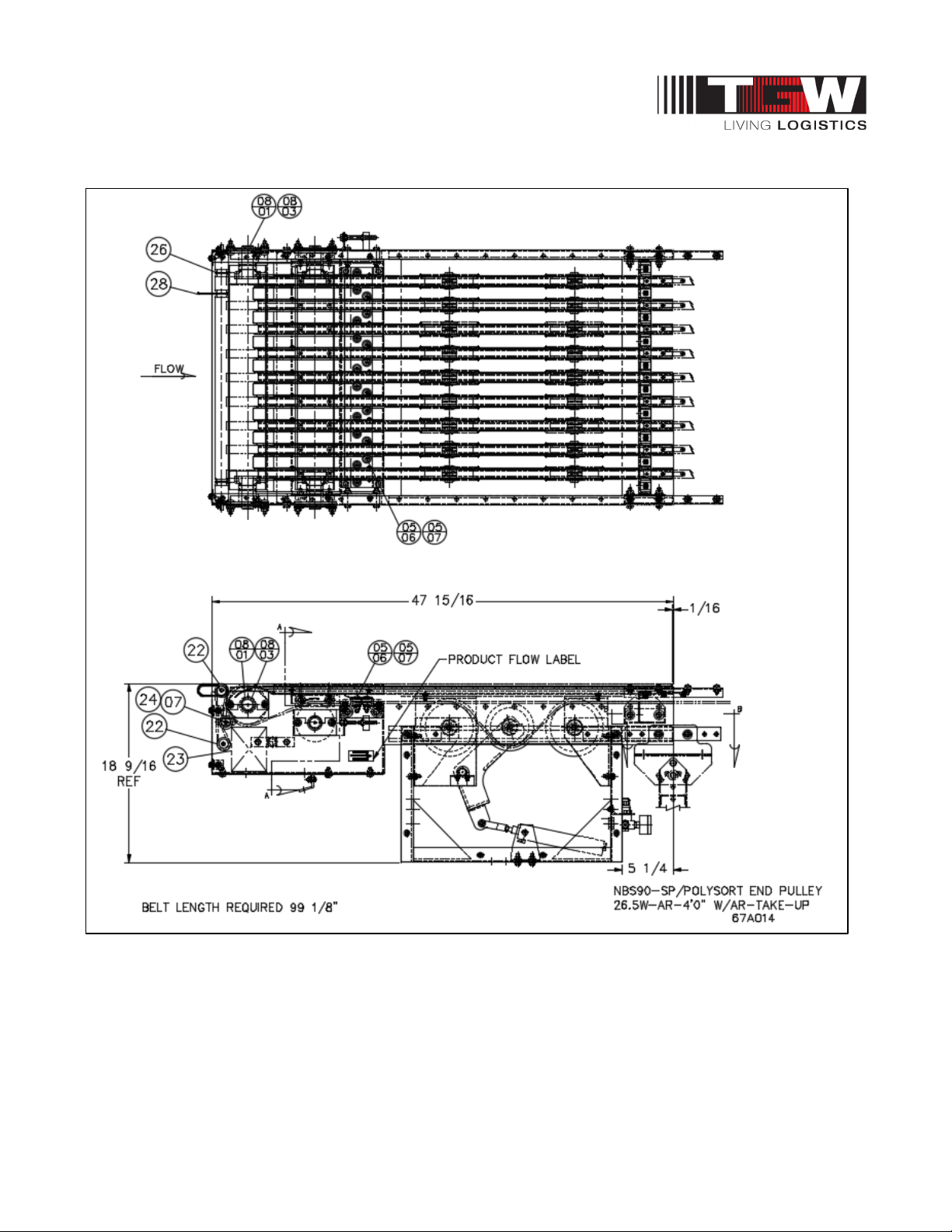
NBS®90 PolySort & SP IOM
11.5: NBS90 POLYSORT END PULLEY AR 4’0” W/AIR TAKE-UP
P/N: 1193974 Revision Date: 4/25/2019 Page 75 of 83
Page 76

NBS®90 PolySort & SP IOM
Balloon Description Width & Item #
7
ROLLER,SLIDE 11/32HEX NBS-SP E0002716
05/06 BRG, R6 ZZ C3 90050111
05/07 ROLLER,SLIDE 11/32HEX NBS-SP E0002332
08/01 PULLEY,4"DIA 26.5NBS-SP
1204198
08/03 COLLAR,ECCENTRIC LOCK 1-3/16"B 90140052
22
ROLLER,SLV 26.5NBS-SP E-PULL 1202529
23 PHOTOEYE,RETO RAY10-PZ5EBL 1203440
24 ROLLER,IDLER 26.5NBS-SP 4"END 1202530
26
ORING,83A 3/16 X 12-1/2" 90530019
28 ORING,83A 5/32 X6-1/4"ST TRANS E0001299
NBS90 PolySort End Pulley Aluminum Rail (AR) 4'0" W/Take-up
ENDPULLEY,NBS SP-26.5W-AR-4'0"-W/AIR TAKEUP
REF DWG# 67A014
11.5.1: Replacement Parts – NBS90 PolySort End Pulley AR 4’0” W/Air Take-up
P/N: 1193974 Revision Date: 4/25/2019 Page 76 of 83
Page 77
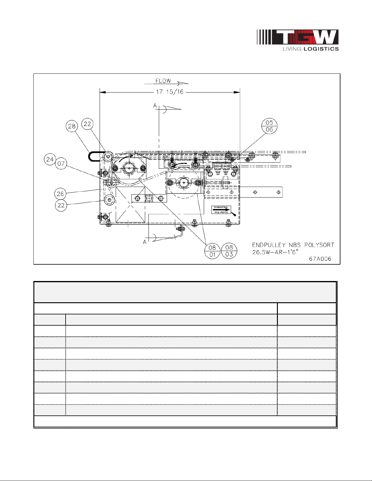
NBS®90 PolySort & SP IOM
Balloon
Description Width & Item #
7
ROLLER,SLIDE 11/32HEX NBS-SP
E0002716
22 ROLLER,SLV 26.5NBS-SP E-PULL
1202529
24 ROLLER,IDLER 26.5NBS-SP 4"END
1202530
26
ORING,83A 3/16 X 12-1/2"
90530019
28 ORING,83A 5/32 X6-1/4"ST TRANS
E0001299
05/06 BRG, R6 ZZ C3 90050111
08/01
PULLEY,4"DIA 26.5NBS-SP C-FF 1-3/16"BORE ECCENTRIC
1204198
08/03 COLLAR,ECCENTRIC LOCK 1-3/16"B
90140052
END PULLEY,NBS SP-26.5W -AR-1'6"
NBS90 PolySort End Pulley Aluminum Rail (AR) 1'6"
REF DWG# 67A006
11.6: NBS90 POLYSORT END PULLEY AR 1’6”
11.6.1: Replacement Parts – NBS90 PolySort End Pulley AR 1’6”
P/N: 1193974 Revision Date: 4/25/2019 Page 77 of 83
Page 78
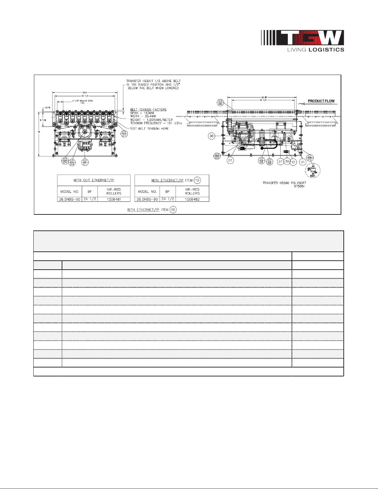
NBS®90 PolySort & SP IOM
Balloon Description Width & Item #
1 LIFTTABLE,NBS-90 POLYSORT 1206338
7 AIRBAG,FIRESTONE #W02-358-3000 90000025
30 SPRING,EXT 3/4OD X 2"LG .075W 90800263
02/02 VALVE,Q UICK EXHAUST #QE3 89000034
02/06 TUBING,3/8"POLYU-95DURO 1/4"ID E0001392
02/08 VALVE,SMC 3WAY 24VDC 2.2CV,W/FITTINGS NBS-SP90 POLYSORT 1206332
03/03 MTR,EURO MOVIMOT 0.75HP 460V,PRESET F1=4.5T1=0 DIPS SET OFF 1203208
03/04
SHEAVE,DRIVE NBS-SP POLY SORT,304SS
1206407
03/06
ROLLER,NBS-SP90-25.5 28BF,NR-RED COATED 1206310
03/07 BELT,HABASIT 1"WIDE X 150.50",#S-10/15 ENDLESS 1202961
10/01 MOD, MOVIMOT,ETHERNET/IP,W/ MFZ21D CONNECTOR BOX 1204731
NBS90 PolySort Transfer
TRANS,NBS-90D-26.5-POLYSORT- 24VDC-NR-RED-ROLLERS WITH OR W ITHOUT ETHERNET
REF DWG# 67S051A
11.7: NBS90 POLYSORT TRANSFER ASSEMBLY
11.7.1: Replacement Parts - NBS90 PolySort Transfer Assembly
P/N: 1193974 Revision Date: 4/25/2019 Page 78 of 83
Page 79
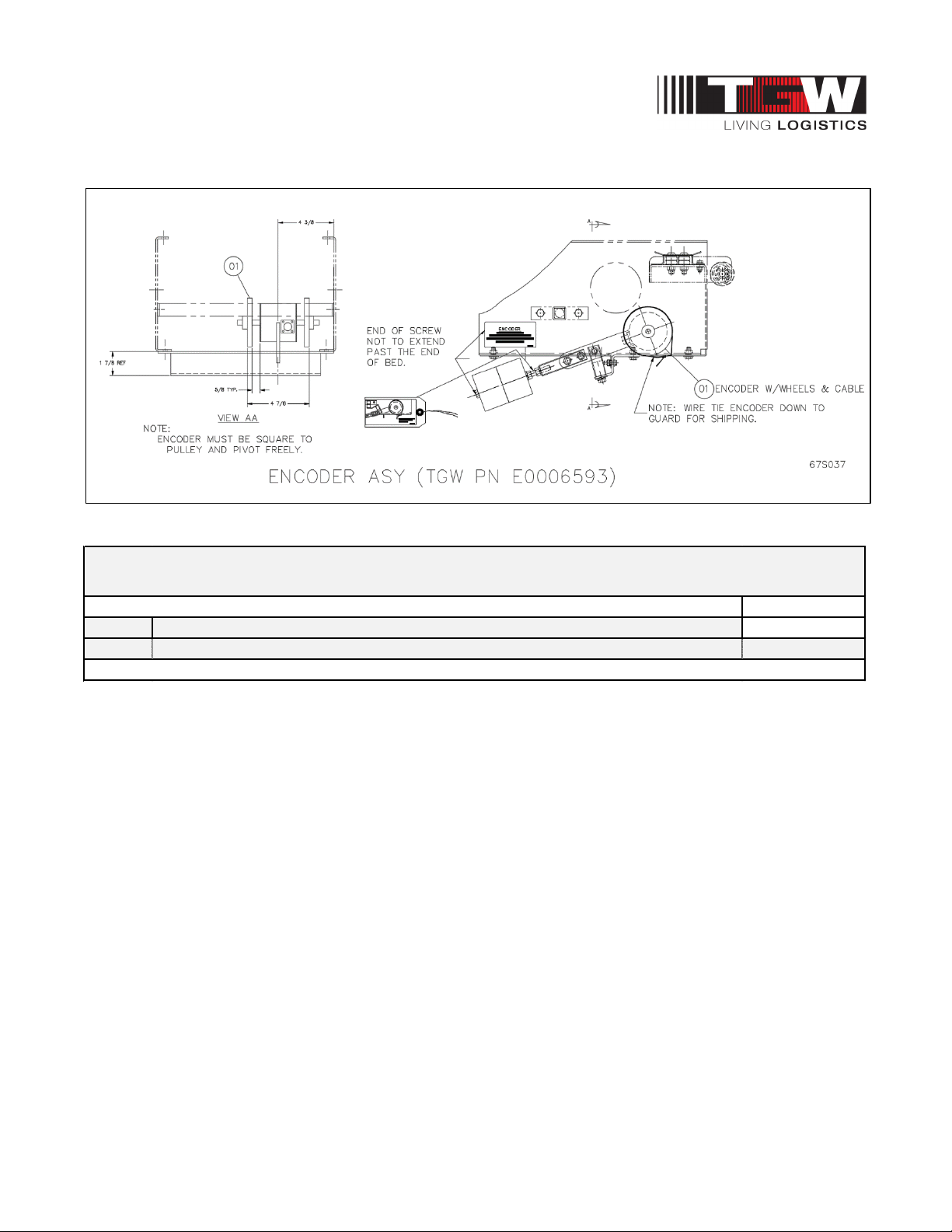
NBS®90 PolySort & SP IOM
Balloon Description Width & Item #
1 ENCODER,PROG,EXT-SHAFT,WHEELS,8-30VOLTS W/(2)# MW-1-B WHEELS E0006585
Encoder with Cable & Connectors
ENCODER,NBS SP-PHOTOCRAFT
REF DWG# 67S037
11.8: NBS90 SP & POLYSORT ENCODER ASSEMBLY
11.8.1: Replacement Parts – NBS90 SP & PolySort Encoder Assembly
P/N: 1193974 Revision Date: 4/25/2019 Page 79 of 83
Page 80
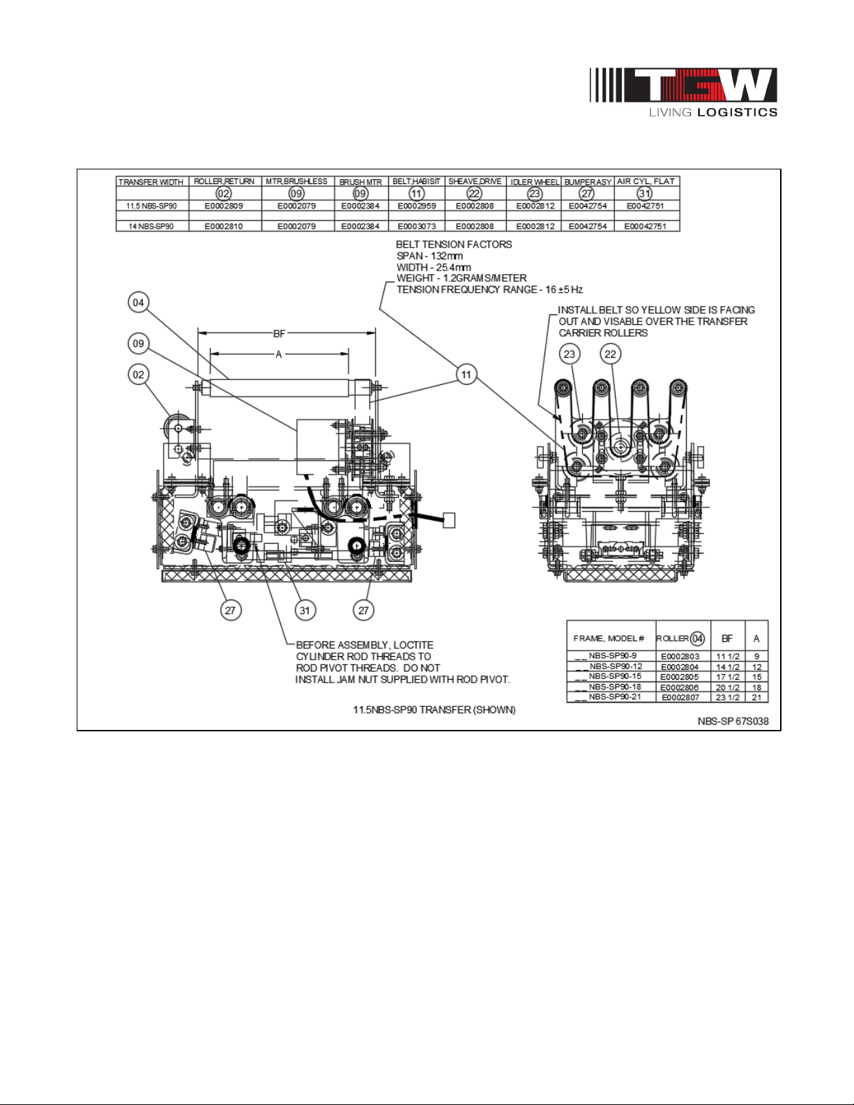
NBS®90 PolySort & SP IOM
11.9: NBS90 SP TRANSFER ASSEMBLY REPLACEMENT PARTS DIAGRAM
P/N: 1193974 Revision Date: 4/25/2019 Page 80 of 83
Page 81
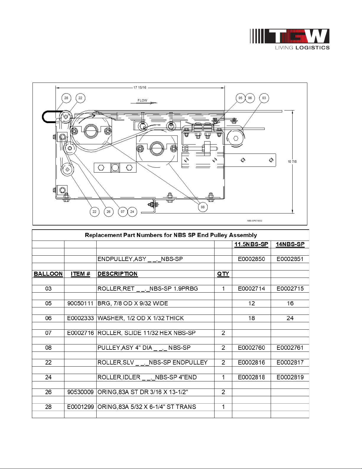
NBS®90 PolySort & SP IOM
11.10: NBS90 SP END PULLEY ASSEMBLY REPLACEMENT PARTS DIAGRAM
P/N: 1193974 Revision Date: 4/25/2019 Page 81 of 83
Page 82

NBS®90 PolySort & SP IOM
WORKS CITED
AISC. (2015). American Institute of Steel Construction. Retrieved 1 14, 2015, from https://www.aisc.org/
ANSI. (2013-2014). American National Standards Institute. Retrieved 2014, from ANSI Standards
Store: http://www.ansi.org/
ASME. (2014). The American Society of Mechanical Engineers. Retrieved 12 05, 2014, from
https://www.asme.org/
CEMA. (2014). Conveyor Equipment Manufacturers Association. Retrieved 2014, from Conveyor
Equipment Manufacturers Association: http://www.cemanet.org/
OSHA. (2014). Occupational Safety & Health Administration. Retrieved 2014, from OSHA QuickTakes:
https://www.osha.gov/
SEW-Eurodrive. (2018). SEW-EURODIVE USA. Retrieved from
http://www.seweurodrive.com/produkt/movimot-gearmotor-with-integrated-frequencyinverter.htm
Tri-Tronics. (2016). Retrieved from Photocraft Tri-Tronics: https://www.ttco.com/encoders/
TGW GENERAL INFORMATION
TGW Website Link:
www.tgw-conveyor.com
TGW Maintenance Videos:
https://www.tgw-conveyor.com/media-center/maintenance-videos
TGW Product Videos:
https://www.tgw-conveyor.com/media-center/video-gallery
Natrix Application and Control Guidelines:
https://www.tgw-conveyor.com/support/application-control-guidelines
TGW IOM Manuals:
https://www.tgw-conveyor.com/support/iom-manuals
Brochures:
https://www.tgw-conveyor.com/support/brochures
After Hours, Contact Information
https://tgw-conveyor.com/tgw/guaranteed-product-performance
P/N: 1193974 Revision Date: 4/25/2019 Page 82 of 83
Page 83

NBS®90 PolySort & SP IOM
TGW SYSTEMS INFORMATION
Mission
TGW Systems, located in Spring Lake, Michigan, is a leading deliverer of “smart” material handling
systems, technologies, products, and services, creating solutions for material flow applications. As a
global supplier of conveyor systems and equipment since 1964, TGW Systems provides sorters,
conveyors, and accessories to satisfy a broad spectrum of accumulation, transportation, and sortation
applications.
TGW Systems Inc.
1300 E. Mount Garfield Road
Norton Shores MI 49441-6097 USA
231.798.4547
Email: [email protected]
Web Site: www.tgw-group.com
Web Site : www.tgw-conveyor.com
Regional sales offices and authorized Business Partners located throughout the United States and
Canada. Licensees and Business Partners in Europe, South America, and Southeast Asia.
P/N: 1193974 Revision Date: 4/25/2019 Page 83 of 83
 Loading...