

TGB Hornet 50, Hornet 90 Service Manual

CONTENT
1. REGULAR INSPECTION -----------------------------------------2
1-1 Delivery Introduction ---------------------------------------------------2
1-2 Inspection Before Running -------------------------------------------4
1-3 Regular Inspection ------------------------------------------------------5
1-4 General Inspection ------------------------------------------------------6
2. MAINTENANCE INFORMATION------------------- ------------7
2-1 Specification Sheet -----------------------------------------------------7
2-2 Maintenance Data ---------------------------- ---------------------------8
2-3 Special Tools --------------------------------------------------------------9
2-4 List of Grease & Oil Adopted ----------------------------------------12
2-5 Circuit Drawings ---------------------------------------------------------13
2-6 Tighting Torque of Screws---------------------------------------------14
2-7 Simplified Troubleshooting -------------------------------------------16
2-8 Troubleshooting ----------------------------------------------------------17
3. DESCRIPTION OF COMPONENTS AND ASSEMBLY ---25
3-1 Cover and Seat -----------------------------------------------------------26
3-2 Engine ----------------------------------------------------------------------27
3-3 Transmission Mechanism --------------------------------------------30
3-4 Electric System -----------------------------------------------------------35
3-5 Body --------------------------------------------------------------------------37
4. DISASSEMBLY REPAIRMENT
4-1 Notice for Disassembly Repairment ------------------------------40
4-2 Removal and lnstallation of Engine -------------------------------41
4-3 Disassembly and Assembly of Engine ---------------------------43
4-4 Removal and Assembly of Carburetor ---------------------------73
4-5 Removal and Inspection and Assembly of Electric Parts --75
4-6 Removal and Inspection and Assembly of Body Parts -----80
------------ ------------------------39
1

CHAPTER I
:
REGULAR INSPECTION
1-1 Delivery Introduction
To inform customers of correct methods to use:
To practically and correctly ride ATV according to the Instruction of
Manual and Maintenance Handbook. Customers should also try in person
according to this manual.
1. Starting:
A. Turn the power switch to "ON."
B. Hold the front or rear brake and press the "START" button.
C. If ATV is not started, release the "START" button
and try again after a few minutes. Each start should be
less than five seconds to avoid battery consumption.
Note: This is Manual CHOKE ATV and the choke lever is in the left handle
bar.
The fuel is controlled only by throttle grip.
The accelerator has to return to its original place when ATV
is not in use.
D. If ATV can not be started by pressing the "START" button, try the kick starter.
2. Fuel:
Inform customers to refill the fuel to no more than 90% of the tank capacity only.
2

1-1 Delivery Introduction
3 . Lubricant Adopted:
A. WARNING : TGB Supper Oil GA50400002 ( OR 2 STROKE OIL in accordance
with JASO FC ) will be adopted as two-stroke engine oil. The engine oil must be
refilled when the oil warning lamp lights, otherwise the engine will be
burned-out due to insufficient lubrication.
B. TGB Gear Oil GA50400004 ( OR SAE 85W-90 )
changed on a periodical basis. Gear oil and engine oil are different in their nature.
Attention should be paid to avoid mistake when used.
4. Regular Inspection and Maintenance:
Inform customers of the importance of inspection before running and regular inspection.
A. Inspection Before Running: Riders should perform inspection by themselves before
running.
B. Regular Inspection: Regular inspection should be performed after the first month and
the three month and every three months afterwards.
5. Description of Warranty System:
Clearly identify the content of warranty in accordance with the warranty paper.
A. Content and term of warranty.
B. Maintenance items not guaranteed.
will be adopted as gear oil to be
C. Items should be followed by customers.
Instruct customers to carry the OWNER'S Manual with them when they come for regular
inspection and maintenance. It is because such inspection should be recorded onto the
Manual.
3
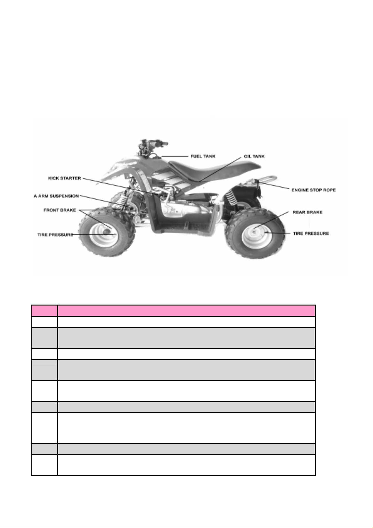
1-2 Inspection Before Running
Items to be Inspected Before Running by Customers:
ITEM CONTENT
Is the oil volume
1. Starter
2 .Fuel
3 . Brake
proper?
Is the fuel volume
sufficient?
Check the distance
of brake handle lever
and the brake effect.
1.Is the air pressure
proper?
2.Groove should be
1.Check Oil Warning Lamp to see if
the oil volume is proper?
1.Check fuel volume to see if it is
enough to the destination.
1.Operate the handle lever slowly to
the brake begin to effect in order to
inspect the moving distance.
2.Test the brake with low speed
running to see the brake effect of
front and rear brakes.
1.Check if the air pressure of tire is
sufficient with a gauge or by sight. The
recommended pressure of tire is 4 p.s.i.
1.Check if the groove of tires is
GUIDELINE
deep enough.
4. Tire
Note: Customers should be informed to perform inspection by themselves before
running in according to this table.
3.Unusual wear is not
desired.
4.Breaking and damage
are not desired.
5.Metal, stone and
other articles are
not desired.
enough.
1.Check landing flat of tire to see if
any unusual wear appears.
1.Check landing flat and side to see
if any breaking or damage appear.
1.Cneck if any cracking, stone or any
other article sticks into the tire.
4
1-3 Regular Inspection
The chart below lists the recommended intervals for all the returned periodic
service work necessarily to keep the motorcycle operating at peak performance
and utmost efficiency. Mileages are expressed in terms of months.
These intervals judged by recorded run-hours or month whichever comes first.
Km
MONTHS
ITEM
Battery
Tire
Brake
Brake fluid
Bolts and nuts
Spark plug
Air cleaner
Final gear oil
Cylinder head nut
exhaust pipe bolts
0
km
0
months
I
I
I
I
I
-
-
1000
km
2
months
I
I
I
I
T
Clean every 3000 km
Replace every 5000 km
T
6000
km
12
months
I
I
I
I
T
R
T
12000
km
24
months
I
I
I
R
T
R
T
18000
km
36
months
I
I
I
I
T
R
T
Steering system
Suspension system
Engine idle rpm
Muffler
Oil pump
Fuel Filter R R R
I
I
I
I
I
I
I
I
I
-
I
I
I
I
I
I
I
I
I
I
I
I
I
I
I
NOTE : I=Inspect and clean, adjust, lubricate or replace, if necessary.
R=Replace
T=Tighten
5
1-4 General Inspection General Inspection and Adjustment
means adjustable.
*
Note:
Special attention should be paid while setting the turning speed of Engine by
Tachometer.
The ignition of ATV by the use of crank-shaft which is 2 ignitions/revolution.
1-5 Notes for Inspection
ITEM
Be aware of smoke and fire while performing maintenance.
1
New Packing, Gasket, O Ring, locking pin should be used while
2
assembling.
Only designated TGB oils should be used on spare parts.
3
Clean the vehicle before maintenance to avoid dirt or mud on
4
disconnected parts.
The locking sequence of Bolt and Nut should be from inside to
5
outside, or in diagonal step. Reverse the sequence to loose.
Special tools should be used when necessary.
6
Attention should be paid to avoid damage or loss of
disconnected parts. Clean and grease properly before the
7
assembly. No grease on Bolt's Thread.
Reconfirm each function after the assembly.
8
Special attention should be paid to the battery's electrolyte
9
and brake oil which will stam clothes.
INSPECTION DETAILS
6
2-1 Specification Sheet
ITEM NO. Hornet 50 Hornet 90
Exhaust Volume 49.3c.c 82.4c.c
Stroke 2T 2T
Overall Length mm 1420 1490
Overall Width mm 870 880
Overall Height mm 905 940
ATV
Weight (Empty)
Maximum Load 95kg 95kg
Tire(tubeless)
Cylinder Type Horizontally Placed
Max Horsepower 3.3ps/5500rpm 5.4ps/5000rpm
Gasoline 92/ 95 Unleaded Gasoline
Lubrication Method Oil Supplied Separately by Oil Pump
Cooling Type for
Engine
Ignition Method C.D.I Ignition device w/o point.
Rim comp Size
Spark Plug
Clearance: 0.6- 0.7mm
112kg 120kg
Front:16 x 8 – 7
Rear: 16 x 8 – 7
Air Cooled by Cooling Fan
Front:7 x 5.2
Rear: 7 x 5.2
BPR7HS (NGK)
BPR7HS –10(NGK)
Clearance :0.9-1.0mm
Front:19 x 7 – 8
Rear: 19 x 8 – 8
Front:8 x 5.5
Rear: 8 x 7.0
Battery 12V/7Ah 12V/7Ah
flywheel magneto Alternating Output:12V-50W Alternating Output:12V-50W
Transmission V-belt Continuous Variable Transmission
Brake
Front: Drum
Rear:Disc
Frame Made of High Resistance Steel Pipes
Oil warning Lamp 3.4W
Fuel Tank 5.6 liters 5.6 liters
Front: Drum
Rear:Disc
7
2.2 Maintenance Data
Cylinder +piston+Crank Shaft
ITEM 50 C.C. 90 C.C.
STANDARD LIMIT STANDARD LIMIT
Cylinder Cover Flatness 0∼0.02 0.1 0~0.02 0.1
Piston Outside Diameter
(15mm above skirt)
Clearance BetweenCylinder and Piston 0.065~0.075 0.12 0.065~0.075 0.12
Bore of Piston Pin 10.002~10.01 10.04 12.004~12.015 12.05
Outside Diameter of Piston Pin 9.995~10.00 9.98 11.995~12.00 11.98
Bore of Small End of Con-Rod 14.003~14.011 14.05 14.996~15.007 15.05
Inside Diameter of Cylinder 41.005~41.020 41.07 5.005~50.020 50.07
Clearance at terminal of piston ring when
assembled in Cylinder.
Radial Clearance of Big-End at Con-Rod 0.1~0.55 1.0 0.1~0.55 1.0
Runout of Crank Shaft 0~0.05 0.1 0~0.05 0.1
CVT
Free Length of Clutch Spring 23.8 25.0 23.8 25.0
Thickness of Clutch Lining 3.0 2.0 3.0 2.0
Bore of Clutch Housing 110~110.15 110.40 110~110.15 110.40
BRAKE
Engine Oil
Ignition
Battery
Brake
Tire Pressure
Bore of Brake Drum 85 85.6 85 85.6
Brake Lining O.D. 84.3 82.3 84.3 82.3
Thickness of Disc Brake Lining 4.7 3.7 4.7 3.7
Capacity 0.9L 0.9L
Residual Capacity when Light on 0.23L 0.23L
Oil Used TGB Super Engine Oil (JASO FC ) TGB Super Engine Oil (JASO FC )
Oil Capacity of Gear Box 90c.c 90c.c
Lead 15°±3°BTDC /4000rpm 15°±3°BTDC /4000rpm
Spark Distance 6-8mm 5mm 6-8mm 5mm
Inner Electric Resistance at Spark Plug Cap 5~7.6kΩ 3kΩ 5~7.6kΩ 3kΩ
Battery 12V/7AH 12V/7AH
Fuse 7A 7A
Clearance of Front Brake Lever 20-30mm 20-30mm
Clearance of Rear Brake Lever 15-35mm 15-35mm
Front (psi) 4 4
Rear (psi) 4 4
40.935~40.95 40.89 49.94~49.955 49.90
0.10~0.25
0.75
(1st&2nd Rings)
0.15~0.35 0.85
8
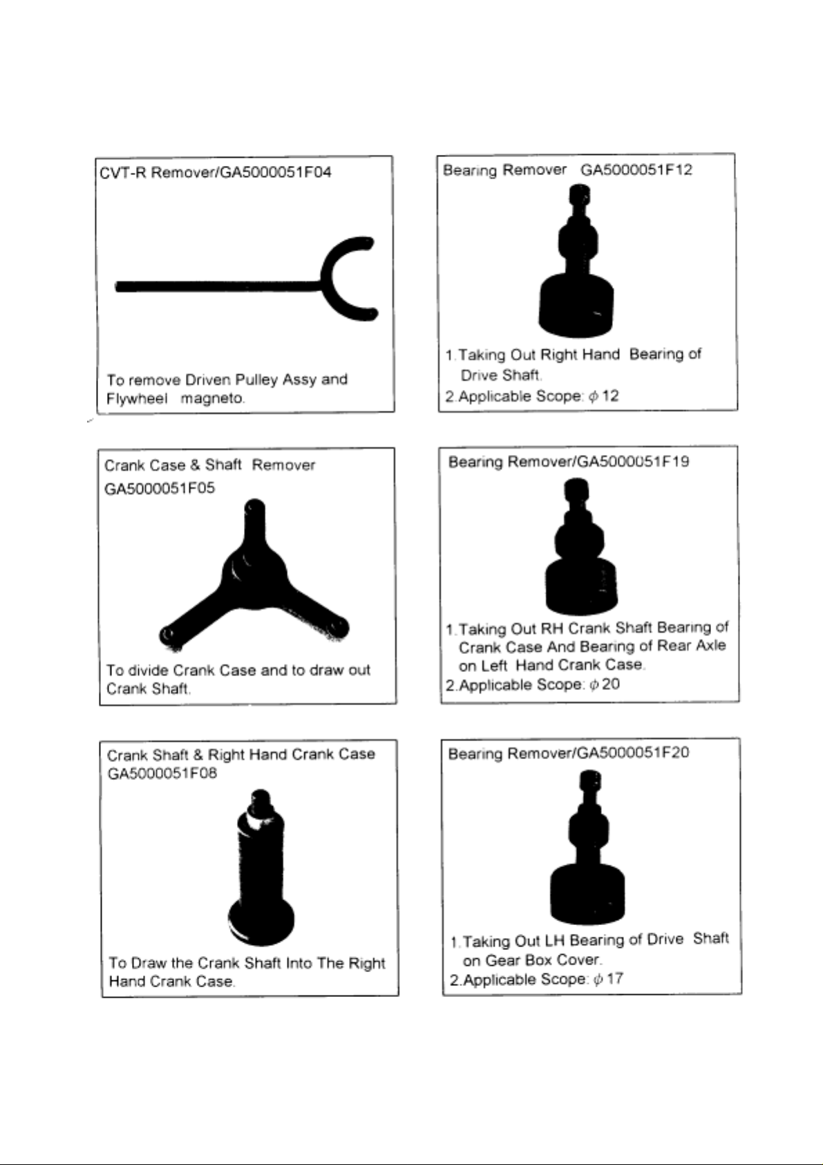
2-3 Special Tools
9
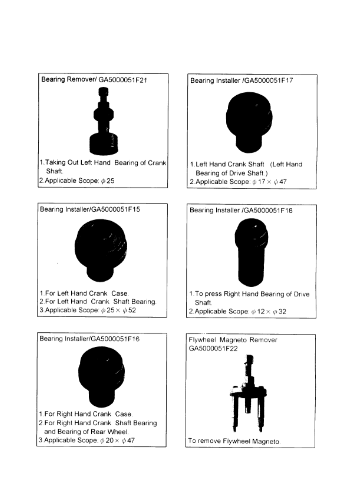
2-3 Special Tools
10
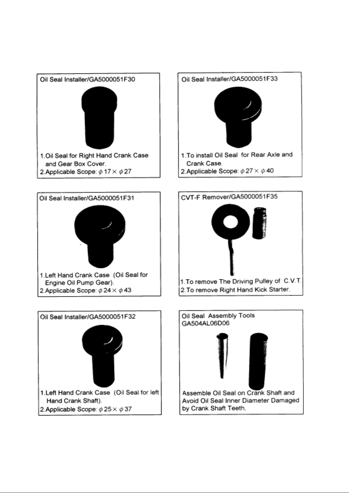
2-3 Special Tools
11
2-4 List of Grease & Oil Adopted:
GA55100001
TGB Supper Grease
No.0
Apply in Oil Seal.
GA50400001
1104 Sealing ThreeBond Apply on Right
Hand Crank Surface.
GA50400002
TGB Supper Oil
GA50400003
Supper Grease No.3
Apply in Axle Shaft,
inside of Oil Seal.
GA50400004
TGB Gear Oil 85w/90
Transmission Gear Oil
for Scooters.
GA55100002
Three-Bond 1322
Under M10 Screw
(JASO FC)
Apply in oil tank
GA50400005
TGB Supper Grease
No. I
Apply in Oil Seal.
GA5040006
TGB Supper Grease
No.2
Apply in Kick Starter.
(For medium fixing) for
Flywheel Magneto.
GA55100003
DOT-3 Brake Oil For
Brake.
GA50400008
TGB Supper Grease
No.4
For Movable Drive Face Comp.
GA50400017
Cemedine 575
Apply in Handle Grip
12
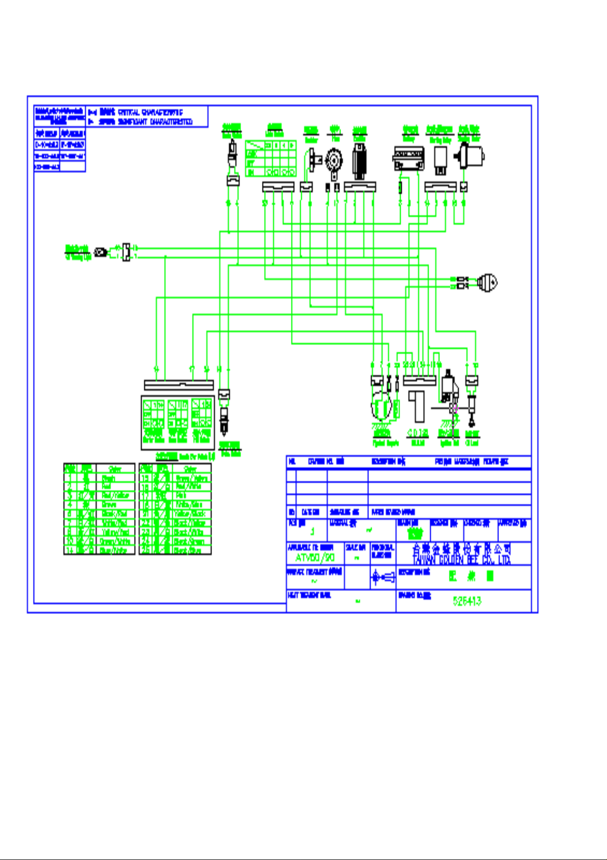
2-5 Circuit Drawing
13
2-6 Tighting Torque of Screws
Screw Torque of Body
tem
I
Locking Location
1 Rear Fork Nut 14 1
2 Crank Case Bracket Nut 10 2 550-600
3 Rear Swing Assy. Nut 8 2 250
4 Rear Swing Assy. Bolt 8 1 250
5 Fixed Nut for Rim 14 4 500~550
6 Self-lock Nut for Rim 10 16 400~450
7 Brake Hose pipe Bolt 10 2 250~300
8 A Arm control linkage Nut 10 4 450~550
9 Front Shock Absorber Nut 10 4 450~550
10 Rear Shock Absorber Bolt 10 2 450~550
11 Steering shaft Assy. Nut 10 2 400~450
12 Steering Linkage Nut 10 4 250
13 Steering Joint Nut 10 4 250~350
14 Steering Shaft Housing Nut 8 2 140~160
15 Steering Stem Lock Nut 14 1 700~750
16 Chain Adjustment Bolt 12 4 500~600
17 Rear Axle Nut 27 1 800
18 Raer Axle Nut 27 1 950
19 Master Cylinder Bolt 6 2 80~120
20 Brake Disc Bolt 10 3 200~250
21 Caliper Bolt 8 2
22 Right handle Lever Bolt 6 100-200
23 Handle-bar Bolt 6 4 100-200
24 Lower Bumper Bolt 8 4 200-300
25 Muffler fixed with frame Bolt 8 1 300-400
26 Chain gear Bolt 8 3 200-250
Thread pcs Torque(kg-cm
600-800
200-250
)
14
2-6 Tighting Torque of Screws
Screw Torque of Engine
Locking Location
Spark Plug
Flywheel Magneto 10 350-450
Nut of Kick Starter, RH 12 400-600
Bolt of Kick Starter 6 80-120
Nut of Driven Pulley Assy. 28 400-600
Nut of Clutch Housing 10 400-600
Bolt of Fuel Inlet 8 90-150
Screw of Fuel Outlet 6 40-70
Bolt of Left engine case 10 550-600
Bolt of Lower left engine case 12 550-600
General Torque
Thread General Bolt kg-cm Heavy Duty Bolt kg-cm
4 10~20 15~30
5 20~40 30~60
8 100~160 80~120
10 220~350 300~400
12 350~550 500~600
)
Thread Torque(kg.cm
250-300
15
2.7 Simplified Troubleshooting
Complaint
No action for
starter motor
No sparking or
poor sparking
Unable or
Difficult to start
I. Fuse breaks.
Possible Reason
2. No power in battery.
3. Defective action of brake switch.
4 Short circuit of starter relay.
I . Defective spark plug.
2. Defective CDI & ignition coil unit.
3. Defective magneto stator coil.
4. Loose connection of lead wire.
Plug not sparking
I. Damaged spark plug or spark plug cap.
2. Dirty or wet spark plug.
3. Defective CDI &ignition coil unit or stator coil.
4.Open or short in high-tension cord.
5. Defective ignition switch.
Remedy
Replace
Charging
Replace
Replace
Replace
Replace
Replace
Connect
Replace
Clean & dry
Replace
Replace
Replace
Noisy engine
Engine idles
No fuel reaching the carburetor
I. No gasoline in fuel tank.
2.Clogged hole in the fuel tank cap.
3.Clogged or defective fuel cock.
4.Clogged fuel hose or defective vacuum hose.
Compression too low
I. Excessively worn cylinder or piston rings.
2.Spark plug too loose.
3. Broken,cracked or otherwise failed piston.
I . Piston or cylinder worn down.
2. Combustion chamber fouled with carbon.
3. Piston pin,bearing or piston pin worn.
4. Worn or burnt crankshaft bearings.
I. Stiff piston ring in place.
Replace
Clean
Clean or replace
Clean or replace
Replace
Tighten
Replace
Replace
Clean
Replace
Replace
Replace
poorly
2. Excessively worn cylinder or piston rings.
3. Gas leaks from crankshaft oil seal.
4. Defective CDI & ignition coil unit.
5. Clogged jets in carburetor.
16
Replace
Replace
Replace
Clean or adjust
17
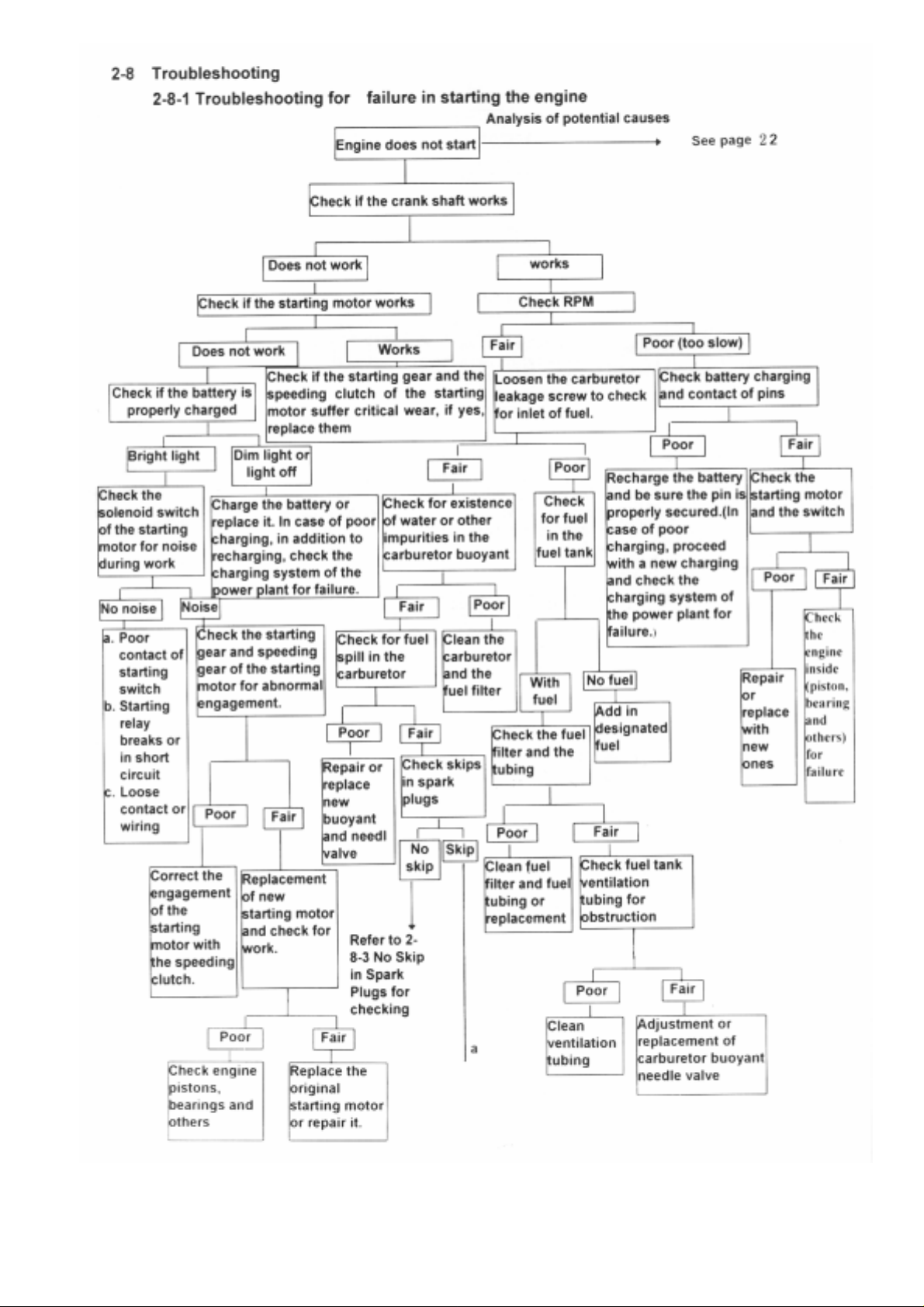
18

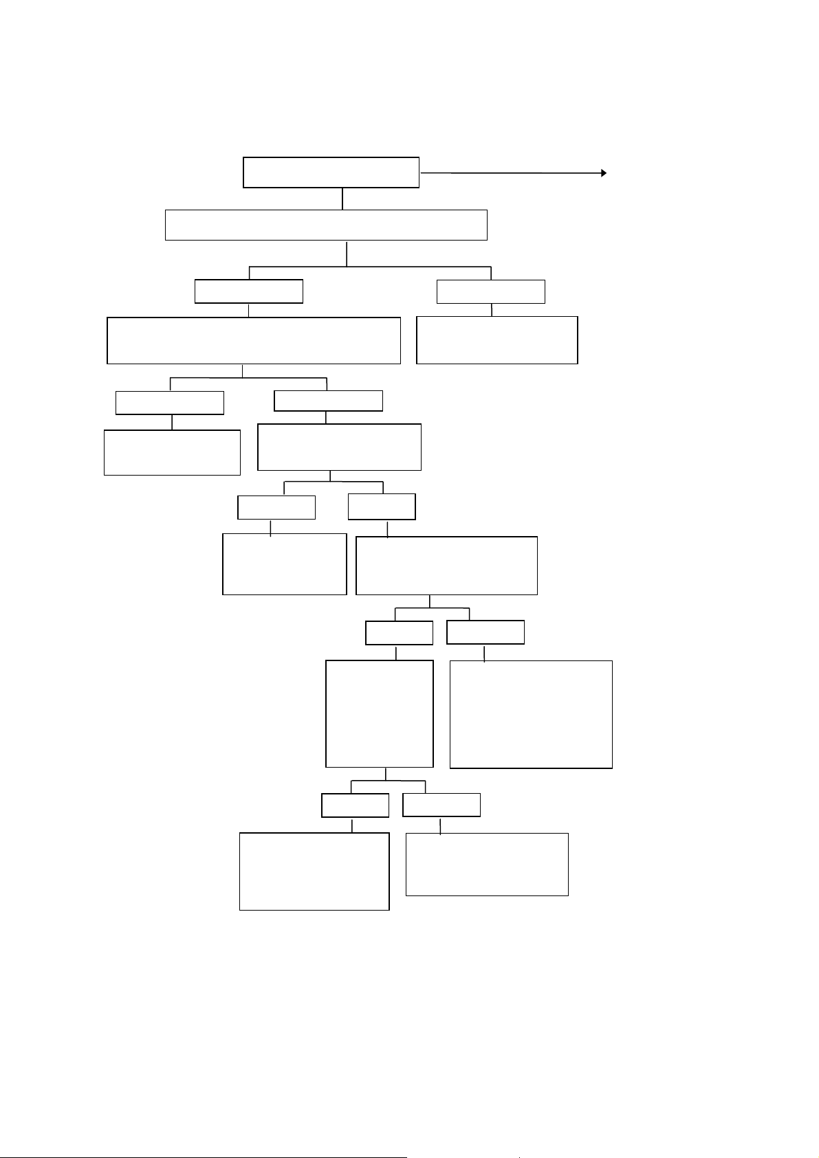
Check item:
○
No fuel
○
Dirty fuel filter
○
Obstructed ventilation tubing of th efuel tank
○
Poor carburector buoyant needle valve
○
Carburetor buoyant with impurities
○
Poor carburetor buoyant
○
No skip in spark plugs
○
Poor skip in spark plugs
○
Dirty spark plugs
○
Incorrect spark plugs gap
○
Dirty and wet spark plugs
○
Loose adjustment screws in the carburetor
○
Carburetor choke
○
Obstructed carburetor slow nozzle
○
Ailing carburetor threshold
○
Obstructed air filter grill
○
Leakage in cylinder washer
○
Seriously damaged cylinder, piston
○
Dead battery
○
Poor contact of battery pin and conductors
○
Starting switch with poor or failure
○
Starting relay with broken wire or short circuit
○
Loose contact and wiring
○
Starting gear and speeding clutch gear seriously worn
○
Starting gear and speeding clutch gear in poor engagement
○
Poor starting motor
19
2-8-2 Troubleshooting for poor skip of spark plugs
20
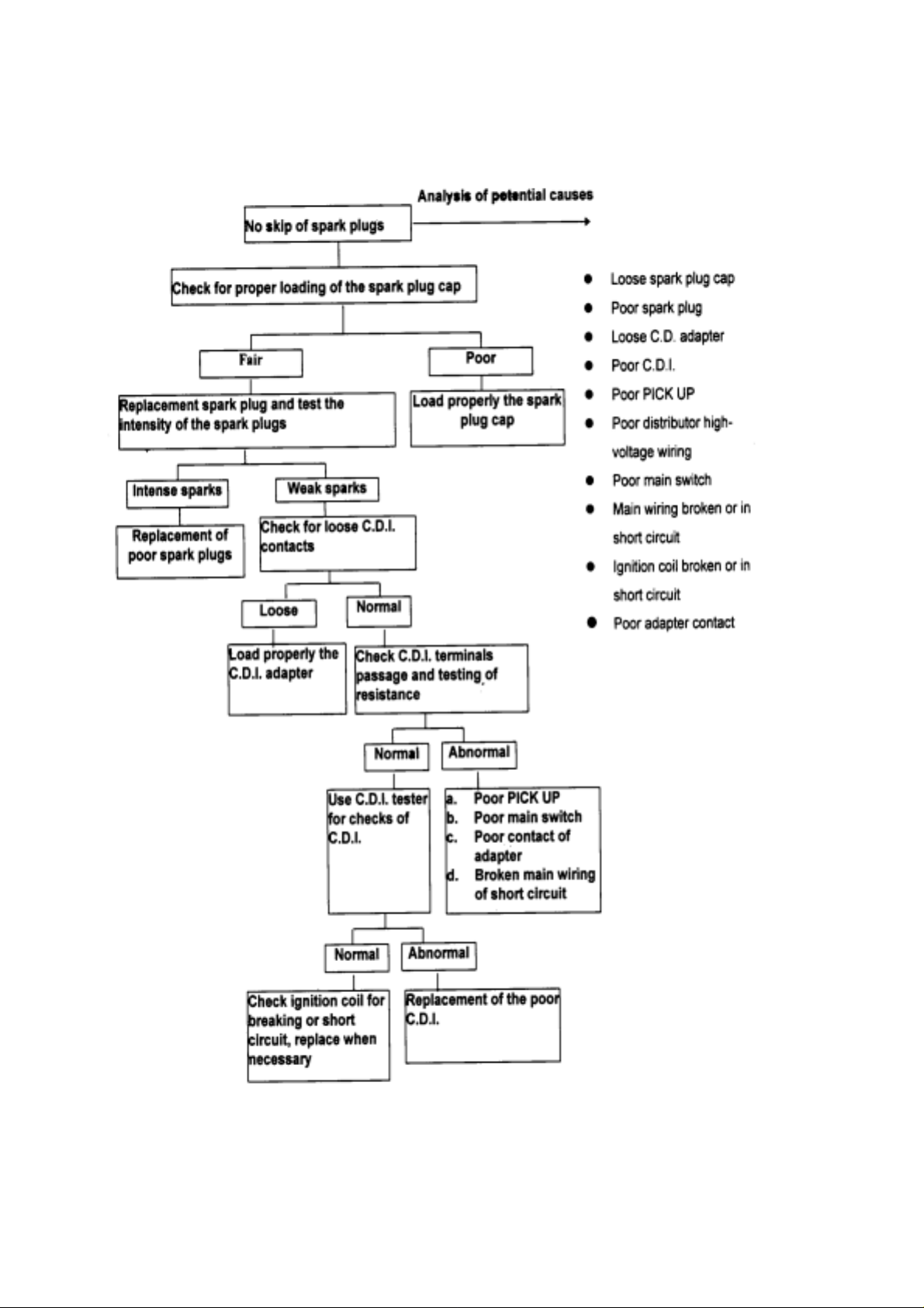
2-8-3 Troubleshooting for no-skip of spark plugs
Replacement spark plug and test the
intensity of the spark plugs
Intense sparks
Replacement of
poor spark plugs
Check for proper loading of the spark plug cap
No skip of spark plugs
Fair
Check for loose C.D.I.
contacts
Loose
Load properly the
C.D.I. adapter
Check ignition coil for
breaking or short
circuit, replace when
necessary
Weak sparks
Normal
Check C.D.I. terminals
passage and testing of
resistance
Use C.D.I. tester
for checks of
C.D.I.
Normal
Normal
Analysis of potential causes
Load properly the spark
Abnormal
Replacement of the
poor C.D.I.
z Loose spark plug cap
z Poor spark plug
z Loose C.D. adapter
z Poor C.D.I.
Poor
plug cap
z Poor PICK UP
z Poor distributor high-
z Poor main switch
z Main wiring broken or in
z Ignition coil broken or in
z Poor adapter contact
Abnormal
a. Poor PICK UP
b. Poor main switch
c. Poor contact of
adapter
d. Broken main wiring
of short circuit
voltage wiring
short circuit
short circuit
21
j
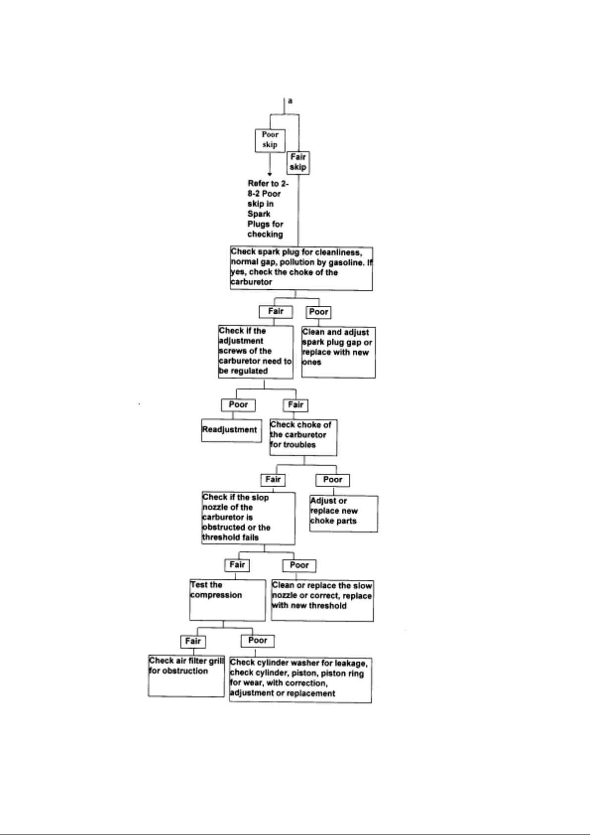
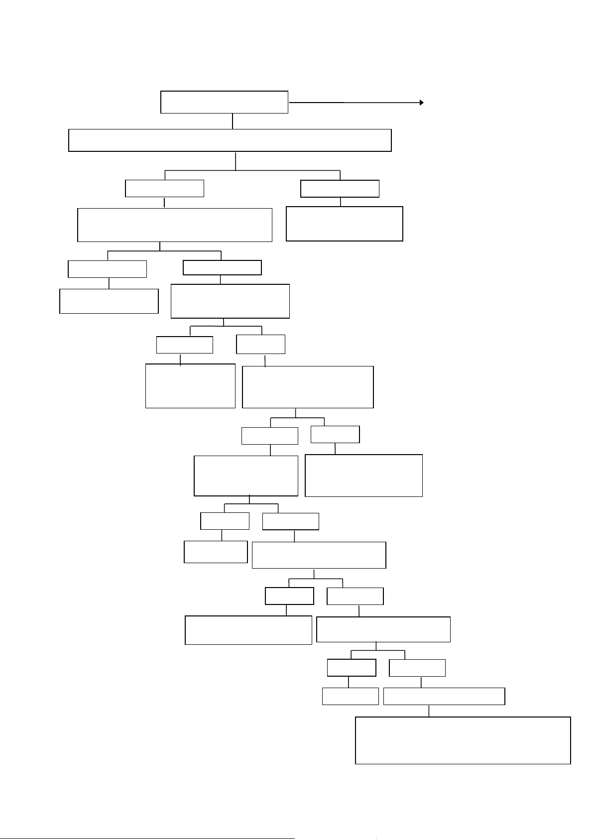
2-8-4 Troubleshooting for slow run (troubled engine)
Check for contamination in spark plugs and excessive gap
Fair
Alarming abnormality of ignition timing
Poor
adjustment
Replacement of
the filter grill
Poor slow run
Is the air filter grill
obstructed?
Poor
Check if the choke valve
fails (valve does not
open) ?
Correction
Add tightening force or
replacement of the washer
Fair
Poor
Fair
Is the carburetor buoyant
level normal ?
Fair
Check of for air between the
carburetor and the air inlet
Analysis of potential causes
Poor
Cleaning and
adjustment
Poor
Adjustment or replacement of
the buoyant needle valve
Fair
Poor
Check for obstruction in
the carburetor slow
Cleaning Test the compression
z Dirty spark plugs
z Incorrect spark
plug gaps
z Incorrect ignition
timing
z Obstructed air
filter grill
z Poor carburetor
buoyant needle
valve
z Poor carburetor
choke valve
z Poor engagement of
carburetor and
inlet tube
z Obstructed
carburetor slow
injection
z Poor engagement of
cylinder head
washer
z Severe wear of
cylinder, piston,
piston ring
Fair
Poor
Check for air leakage in the cylinder washer,
check wear of cylinder, piston, piston ring
Fair
and other elements with correction,
ad
ustment or replacement
22
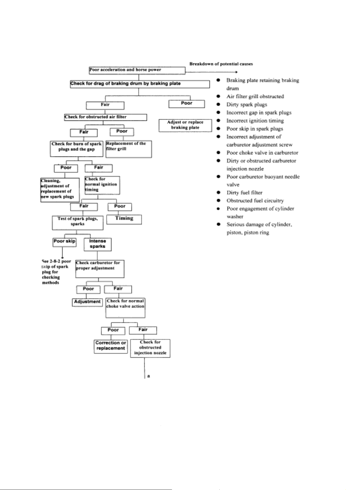
2-8-5 Poor acceleration and horse power
23
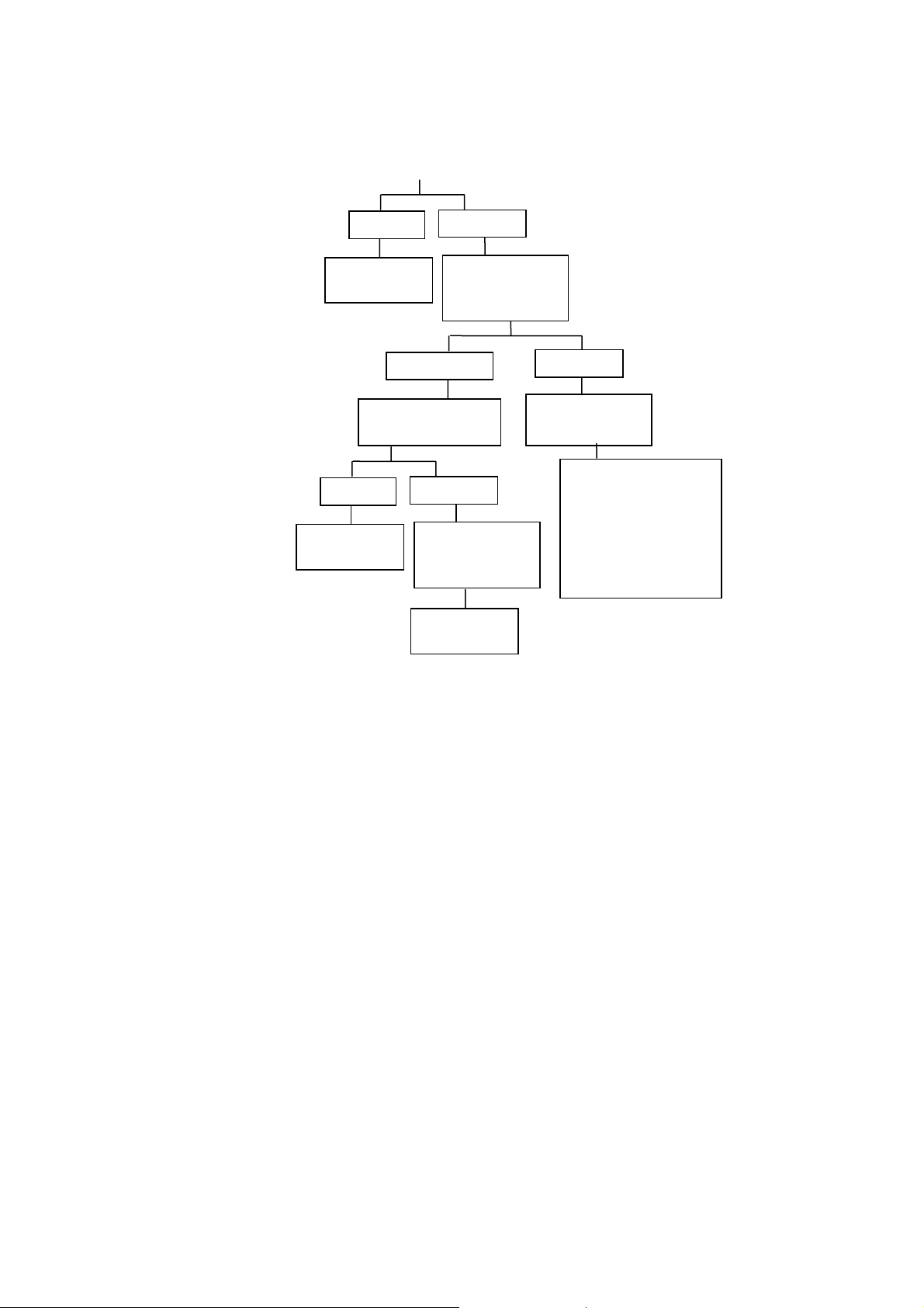
a
Poor
Cleaning or
Poor (low
Check of needle
Poor
Adjustment
Check fuel pipe
for obstruction
Cleaning or
Fair
Check for
normal fluid
level in the
Check the
Fair
and carburetor
Fair
Check for leakage in
cylinder washer;
check cylinder,
piston, piston ring
for wear. Correct,
adjustment or
replacement when
24

CHAPTER 3. DESCRIPTION OF COMPONENTS AND ASSEMBLY
3-1 COVER AND SEAT
3-1-1 Cover
3-1-2 Seat
3-2 ENGINE
3-2-1 Combustion & Air In-Take & Exhaust System
3-2-2 Carburetor
3-2-3 Lubrication & Cooling System
3-3 TRANSMISSION MECHANISM
3-3-1 Power Transmission
3-3-2 Continuous Variable Transmission
3-3-3 Reducing Gear
3-3-4 Kick Starter
3-4 ELECTRIC SYSTEM
3-4-1 Ignition & Battery Device
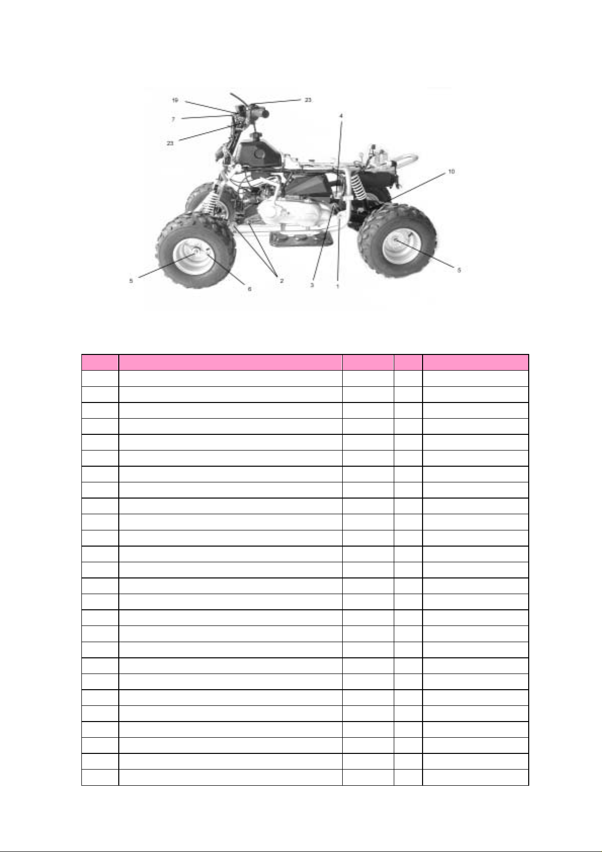
3-5 BODY
3-5-1 Frame, Fuel and Oil System
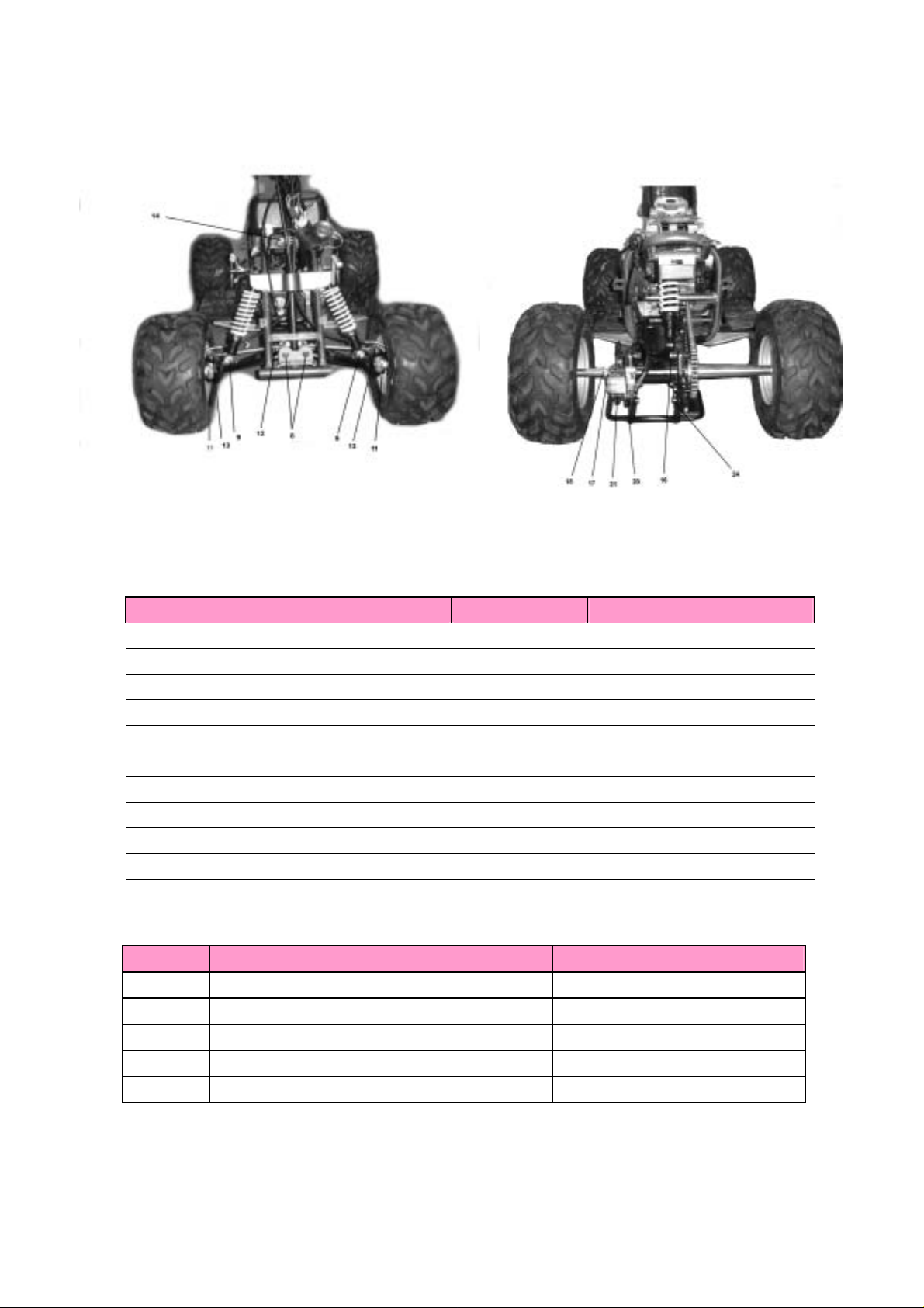
3-5-2 Front & Rear Suspension System
3-5-3 Brake System
25
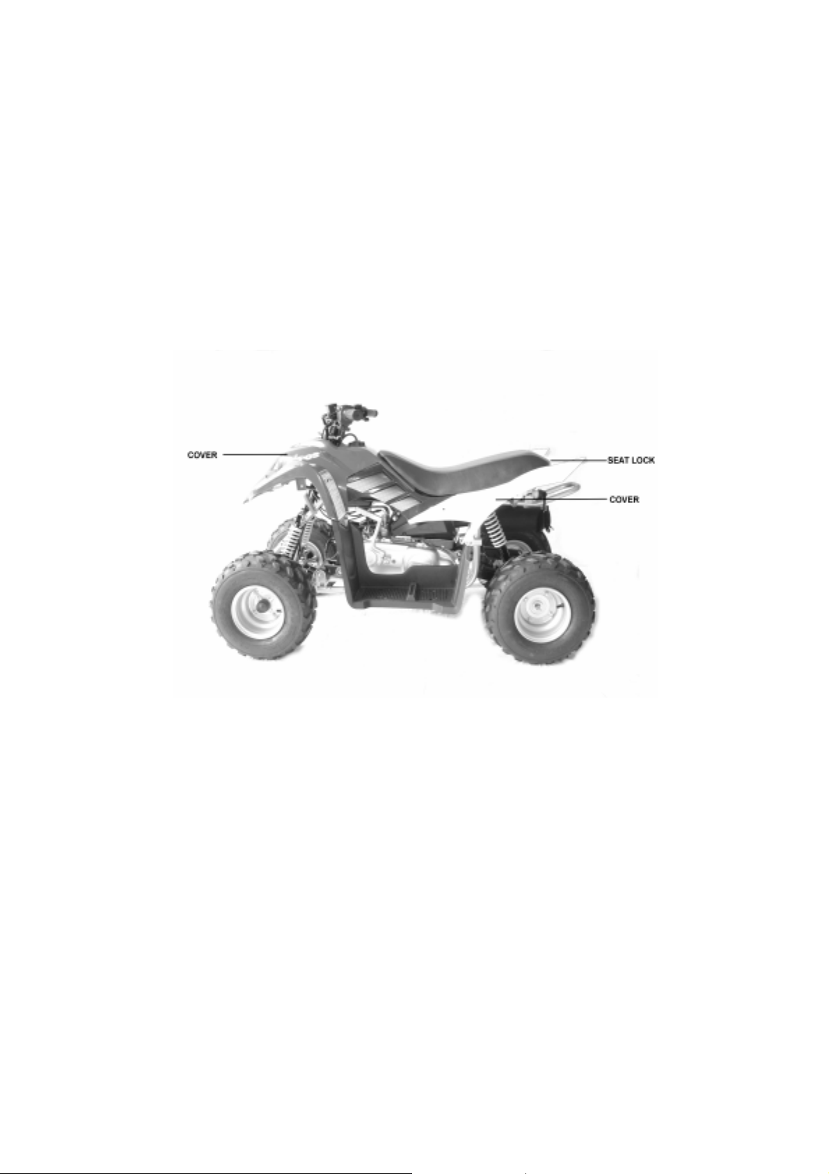
3-1 COVER AND SEAT
3-1-1 COVER
A. The cover of the ATV can be cleaned with vacuum cleaner. It can also
be washed and put back after dried. (please do not wash with volatile
fluid, such as gasoline)
If thecovers were damaged, please replace the new covers. Otherwise,
B.
the covers will cause the injury.
3-1-2 SEAT
A. The seat has to be locked. If theseat is not locked during riding, it will
be affect tehsafety and even cause injury.
B. The seat is controlled by the seat lock on the rear.
26
 Loading...